EP4541941A1 - Electrode structure, gas diffusion layer, and water electrolyzer - Google Patents
Electrode structure, gas diffusion layer, and water electrolyzer Download PDFInfo
- Publication number
- EP4541941A1 EP4541941A1 EP24204885.8A EP24204885A EP4541941A1 EP 4541941 A1 EP4541941 A1 EP 4541941A1 EP 24204885 A EP24204885 A EP 24204885A EP 4541941 A1 EP4541941 A1 EP 4541941A1
- Authority
- EP
- European Patent Office
- Prior art keywords
- gas diffusion
- diffusion layer
- catalyst
- layer
- penetration
- Prior art date
- Legal status (The legal status is an assumption and is not a legal conclusion. Google has not performed a legal analysis and makes no representation as to the accuracy of the status listed.)
- Pending
Links
Images



Classifications
-
- C—CHEMISTRY; METALLURGY
- C25—ELECTROLYTIC OR ELECTROPHORETIC PROCESSES; APPARATUS THEREFOR
- C25B—ELECTROLYTIC OR ELECTROPHORETIC PROCESSES FOR THE PRODUCTION OF COMPOUNDS OR NON-METALS; APPARATUS THEREFOR
- C25B1/00—Electrolytic production of inorganic compounds or non-metals
- C25B1/01—Products
- C25B1/02—Hydrogen or oxygen
- C25B1/04—Hydrogen or oxygen by electrolysis of water
-
- C—CHEMISTRY; METALLURGY
- C25—ELECTROLYTIC OR ELECTROPHORETIC PROCESSES; APPARATUS THEREFOR
- C25B—ELECTROLYTIC OR ELECTROPHORETIC PROCESSES FOR THE PRODUCTION OF COMPOUNDS OR NON-METALS; APPARATUS THEREFOR
- C25B11/00—Electrodes; Manufacture thereof not otherwise provided for
- C25B11/02—Electrodes; Manufacture thereof not otherwise provided for characterised by shape or form
- C25B11/03—Electrodes; Manufacture thereof not otherwise provided for characterised by shape or form perforated or foraminous
- C25B11/031—Porous electrodes
- C25B11/032—Gas diffusion electrodes
-
- C—CHEMISTRY; METALLURGY
- C25—ELECTROLYTIC OR ELECTROPHORETIC PROCESSES; APPARATUS THEREFOR
- C25B—ELECTROLYTIC OR ELECTROPHORETIC PROCESSES FOR THE PRODUCTION OF COMPOUNDS OR NON-METALS; APPARATUS THEREFOR
- C25B11/00—Electrodes; Manufacture thereof not otherwise provided for
- C25B11/04—Electrodes; Manufacture thereof not otherwise provided for characterised by the material
- C25B11/051—Electrodes formed of electrocatalysts on a substrate or carrier
- C25B11/052—Electrodes comprising one or more electrocatalytic coatings on a substrate
-
- C—CHEMISTRY; METALLURGY
- C25—ELECTROLYTIC OR ELECTROPHORETIC PROCESSES; APPARATUS THEREFOR
- C25B—ELECTROLYTIC OR ELECTROPHORETIC PROCESSES FOR THE PRODUCTION OF COMPOUNDS OR NON-METALS; APPARATUS THEREFOR
- C25B11/00—Electrodes; Manufacture thereof not otherwise provided for
- C25B11/04—Electrodes; Manufacture thereof not otherwise provided for characterised by the material
- C25B11/051—Electrodes formed of electrocatalysts on a substrate or carrier
- C25B11/055—Electrodes formed of electrocatalysts on a substrate or carrier characterised by the substrate or carrier material
- C25B11/069—Electrodes formed of electrocatalysts on a substrate or carrier characterised by the substrate or carrier material consisting of at least one single element and at least one compound; consisting of two or more compounds
-
- C—CHEMISTRY; METALLURGY
- C25—ELECTROLYTIC OR ELECTROPHORETIC PROCESSES; APPARATUS THEREFOR
- C25B—ELECTROLYTIC OR ELECTROPHORETIC PROCESSES FOR THE PRODUCTION OF COMPOUNDS OR NON-METALS; APPARATUS THEREFOR
- C25B9/00—Cells or assemblies of cells; Constructional parts of cells; Assemblies of constructional parts, e.g. electrode-diaphragm assemblies; Process-related cell features
- C25B9/17—Cells comprising dimensionally-stable non-movable electrodes; Assemblies of constructional parts thereof
- C25B9/19—Cells comprising dimensionally-stable non-movable electrodes; Assemblies of constructional parts thereof with diaphragms
- C25B9/23—Cells comprising dimensionally-stable non-movable electrodes; Assemblies of constructional parts thereof with diaphragms comprising ion-exchange membranes in or on which electrode material is embedded
-
- H—ELECTRICITY
- H01—ELECTRIC ELEMENTS
- H01M—PROCESSES OR MEANS, e.g. BATTERIES, FOR THE DIRECT CONVERSION OF CHEMICAL ENERGY INTO ELECTRICAL ENERGY
- H01M4/00—Electrodes
- H01M4/86—Inert electrodes with catalytic activity, e.g. for fuel cells
- H01M4/8605—Porous electrodes
-
- H—ELECTRICITY
- H01—ELECTRIC ELEMENTS
- H01M—PROCESSES OR MEANS, e.g. BATTERIES, FOR THE DIRECT CONVERSION OF CHEMICAL ENERGY INTO ELECTRICAL ENERGY
- H01M4/00—Electrodes
- H01M4/86—Inert electrodes with catalytic activity, e.g. for fuel cells
- H01M4/88—Processes of manufacture
- H01M4/8803—Supports for the deposition of the catalytic active composition
- H01M4/8807—Gas diffusion layers
-
- H—ELECTRICITY
- H01—ELECTRIC ELEMENTS
- H01M—PROCESSES OR MEANS, e.g. BATTERIES, FOR THE DIRECT CONVERSION OF CHEMICAL ENERGY INTO ELECTRICAL ENERGY
- H01M8/00—Fuel cells; Manufacture thereof
- H01M8/02—Details
- H01M8/0202—Collectors; Separators, e.g. bipolar separators; Interconnectors
-
- H—ELECTRICITY
- H01—ELECTRIC ELEMENTS
- H01M—PROCESSES OR MEANS, e.g. BATTERIES, FOR THE DIRECT CONVERSION OF CHEMICAL ENERGY INTO ELECTRICAL ENERGY
- H01M8/00—Fuel cells; Manufacture thereof
- H01M8/02—Details
- H01M8/0202—Collectors; Separators, e.g. bipolar separators; Interconnectors
- H01M8/023—Porous and characterised by the material
-
- H—ELECTRICITY
- H01—ELECTRIC ELEMENTS
- H01M—PROCESSES OR MEANS, e.g. BATTERIES, FOR THE DIRECT CONVERSION OF CHEMICAL ENERGY INTO ELECTRICAL ENERGY
- H01M8/00—Fuel cells; Manufacture thereof
- H01M8/10—Fuel cells with solid electrolytes
- H01M8/1004—Fuel cells with solid electrolytes characterised by membrane-electrode assemblies [MEA]
-
- C—CHEMISTRY; METALLURGY
- C25—ELECTROLYTIC OR ELECTROPHORETIC PROCESSES; APPARATUS THEREFOR
- C25B—ELECTROLYTIC OR ELECTROPHORETIC PROCESSES FOR THE PRODUCTION OF COMPOUNDS OR NON-METALS; APPARATUS THEREFOR
- C25B3/00—Electrolytic production of organic compounds
- C25B3/01—Products
- C25B3/03—Acyclic or carbocyclic hydrocarbons
-
- C—CHEMISTRY; METALLURGY
- C25—ELECTROLYTIC OR ELECTROPHORETIC PROCESSES; APPARATUS THEREFOR
- C25B—ELECTROLYTIC OR ELECTROPHORETIC PROCESSES FOR THE PRODUCTION OF COMPOUNDS OR NON-METALS; APPARATUS THEREFOR
- C25B9/00—Cells or assemblies of cells; Constructional parts of cells; Assemblies of constructional parts, e.g. electrode-diaphragm assemblies; Process-related cell features
- C25B9/70—Assemblies comprising two or more cells
- C25B9/73—Assemblies comprising two or more cells of the filter-press type
- C25B9/77—Assemblies comprising two or more cells of the filter-press type having diaphragms
-
- H—ELECTRICITY
- H01—ELECTRIC ELEMENTS
- H01M—PROCESSES OR MEANS, e.g. BATTERIES, FOR THE DIRECT CONVERSION OF CHEMICAL ENERGY INTO ELECTRICAL ENERGY
- H01M8/00—Fuel cells; Manufacture thereof
- H01M8/10—Fuel cells with solid electrolytes
- H01M2008/1095—Fuel cells with polymeric electrolytes
-
- Y—GENERAL TAGGING OF NEW TECHNOLOGICAL DEVELOPMENTS; GENERAL TAGGING OF CROSS-SECTIONAL TECHNOLOGIES SPANNING OVER SEVERAL SECTIONS OF THE IPC; TECHNICAL SUBJECTS COVERED BY FORMER USPC CROSS-REFERENCE ART COLLECTIONS [XRACs] AND DIGESTS
- Y02—TECHNOLOGIES OR APPLICATIONS FOR MITIGATION OR ADAPTATION AGAINST CLIMATE CHANGE
- Y02E—REDUCTION OF GREENHOUSE GAS [GHG] EMISSIONS, RELATED TO ENERGY GENERATION, TRANSMISSION OR DISTRIBUTION
- Y02E60/00—Enabling technologies; Technologies with a potential or indirect contribution to GHG emissions mitigation
- Y02E60/30—Hydrogen technology
- Y02E60/36—Hydrogen production from non-carbon containing sources, e.g. by water electrolysis
Definitions
- a subject matter disclosed in this specification relates to an electrode structure, a gas diffusion layer, and a water electrolyzer.
- a membrane-electrode-assembly (MEA) is used in the fields of fuel cells, water electrolyzers and others.
- the MEA has high catalyst activity, encourages reaction in a fuel cell or an electrolytic hydrogen generating cell, and realizes high efficiency of electricity generation. Furthermore, as the MEA generates no CO 2 during energy conversion, using the MEA achieves reduction in environmental load.
- the MEA generally has an electrode structure with a catalyst layer and a gas diffusion layer (GDL) stacked sequentially on each of both sides of a polymer electrolyte membrane (PEM).
- GDL gas diffusion layer
- PEM polymer electrolyte membrane
- the MEA is manufactured by a method using a known process of providing catalyst layers on an electrolyte membrane and interposing the catalyst layers and the electrolyte membrane using gas diffusion layers in a pair, or using a known process of bonding gas diffusion layers in a pair each provided with a catalyst layer to an electrolyte membrane.
- the catalyst layer is formed by a method using a known process such as a die coating process, a spray coating process, or a decal process, for example.
- the spray coating process is a process of forming a coating film on a base material by spraying a liquid catalyst material.
- the decal process is a process of bonding a solid catalyst material in a film form or in a sheet form directly to a base material. It is generally difficult to improve productivity using these processes.
- the die coating process is a process of applying a liquid catalyst material directly to a base material from a die nozzle and is suitable for producing MEAs in large quantity.
- the present invention is intended to provide a technique allowing reduction in the amount of usage of a catalyst material while alleviating performance degradation of a gas diffusion layer.
- a first aspect is intended for an electrode structure.
- the electrode structure according to the first aspect comprises: an electrolyte membrane; a porous gas diffusion layer positioned on one side of the electrolyte membrane; and a catalyst layer formed from a catalyst material and positioned between the electrolyte membrane and the gas diffusion layer.
- a penetration part formed in the gas diffusion layer by the penetration of the catalyst material having a thickness of 1 ⁇ m or less.
- a second aspect is intended for an electrode structure.
- the electrode structure according to the second aspect comprises: an electrolyte membrane; a porous gas diffusion layer positioned on one side of the electrolyte membrane; and a catalyst layer formed from a catalyst material and positioned between the electrolyte membrane and the gas diffusion layer.
- a penetration part present in the gas diffusion layer by the penetration of the catalyst material having a thickness of one-tenth or less of the thickness of the catalyst layer.
- a third aspect is intended for an electrode structure according to the first aspect or the second aspect.
- the gas diffusion layer includes an anti-penetration layer positioned on the catalyst layer. The anti-penetration layer prevents penetration of the catalyst material.
- a fourth aspect is intended for a porous gas diffusion layer.
- the gas diffusion layer according to the fourth aspect comprises an anti-penetration layer provided on a side where a catalyst layer containing a catalyst material is positioned.
- the anti-penetration layer contains an anti-penetration agent for prevents the penetration of the catalyst material.
- a fifth aspect is intended for a water electrolyzer for electrolysis of water.
- the water electrolyzer according to the fifth aspect comprises the electrode structure according to any one of the first to third aspects.
- the electrode structures according to the first to third aspects it is possible to reduce penetration of the catalyst material into the gas diffusion layer. This allows reduction in the amount of usage of the catalyst material while alleviating reduction in gas diffusion efficiency.
- the presence of the anti-penetration layer makes it possible to reduce penetration of the catalyst material into the gas diffusion layer.
- the presence of the anti-penetration layer makes it possible to reduce penetration of the catalyst material into the gas diffusion layer.
- the water electrolyzer according to the fifth aspect it is possible to reduce penetration of the catalyst material into the gas diffusion layer. This allows reduction in the amount of usage of the catalyst material while alleviating performance degradation of the gas diffusion layer.
- Fig. 1 is a schematic view showing a water electrolyzer 1 according to one preferred embodiment.
- the water electrolyzer 1 is a device that produces hydrogen through solid polymer water electrolysis. As shown in Fig. 1 , the water electrolyzer 1 includes a cell stack 2 and a power supply 3.
- the cell stack 2 includes a plurality of cells 4 and a plurality of separators 5.
- the cell stack 2 is constructed by alternately stacking the cells 4 and the separators 5.
- a direction in which the cells 4 and the separators 5 are stacked will be called a "stacking direction.”
- the power supply 3 applies a voltage to the cell stack 2.
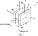
- Fig. 2 is a perspective view schematically showing the cell 4 of the water electrolyzer 1 shown in Fig. 1 .
- the cell 4 includes an electrolyte membrane 41, gas diffusion layers 43 in a pair, and catalyst layers 45 in a pair.
- a stacked body composed of the electrolyte membrane 41, the gas diffusion layers 43 in a pair, and the catalyst layers 45 in a pair is called a membrane-electrode-assembly (MEA).
- MEA membrane-electrode-assembly
- This membrane-electrode-assembly is an example of an "electrode structure.”
- the electrolyte membrane 41 is a ion-conductive membrane (ion-exchange membrane) and has insulating properties.
- a fluorine-based or hydrocarbon-based polymer electrolyte membrane can be used as the electrolyte membrane 41, for example. More specifically, a polymer electrolyte membrane containing perfluorocarbon sulfonic acid can be used as the electrolyte membrane 41.
- the gas diffusion layers 43 are positioned one by one on both sides of the electrolyte membrane 41.
- the gas diffusion layer 43 is a member having electrical conductivity and is composed of a porous member. Carbon paper or carbon cloth can be used as the gas diffusion layer 43, for example.
- the catalyst layer 45 is positioned between the electrolyte membrane 41 and the gas diffusion layer 43.
- the catalyst layer 45 is formed from a catalyst material.
- the catalyst material contains catalyst metal such as platinum (Pt), a platinum alloy, or a platinum compound, for example.
- the platinum alloy may be an alloy of at least one type of metal and platinum, and the at least one type of metal is selected from a group consisting of ruthenium (Ru), palladium (Pd), nickel (Ni), molybdenum (Mo), iridium (Ir), and iron (Fe), for example.
- the oxygen gas generated on the anode side passes through the gas diffusion layer 43 on the anode side and is then output.
- the hydrogen ions generated on the anode side pass through the electrolyte membrane 41 and then move to a cathode side.
- the hydrogen ions (H + ) that have migrated from the anode react with electrons (e - ) to generate hydrogen gas (H 2 ). This reaction is represented by the following formula.
- the hydrogen gas generated on the cathode side passes through the gas diffusion layer 43 on the cathode side and is then output.
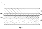
- Fig. 3 is an enlarged sectional view showing a section of a part of the cell 4 shown in Fig. 2 .
- the gas diffusion layer 43 includes an anti-penetration layer 431.
- the anti-penetration layer 431 is designed to prevent the penetration of the catalyst material.
- the anti-penetration layer 431 is a surface layer of the gas diffusion layer 43 adjacent to the catalyst layer 45.
- the anti-penetration layer 431 is formed by performing an anti-penetration process on the gas diffusion layer 43, as will be described later.
- the provision of the anti-penetration layer 431 at the gas diffusion layer 43 is not an absolute necessity but the anti-penetration layer 431 is omissible.
- the gas diffusion layer 43 includes a penetration part 433.
- the penetration part 433 is formed by the penetration of the catalyst material from in the catalyst layer 45 into the gas diffusion layer 43.
- the thickness of the penetration part 433 (the thickness thereof in the stacking direction) is for example equal to or less than 1 ⁇ m,.
- the thickness of the penetration part 433 is equal to or less than one-tenth of the thickness of the catalyst layer 45.
- Fig. 4 illustrates a first flow of manufacturing for the cell 4 shown in Fig. 2 .
- an anti-penetration process is applied to the surface of the gas diffusion layer 43 (step S11).
- the anti-penetration process involves applying an anti-penetration agent for preventing penetration of the catalyst material, for example.
- the catalyst material ink hereinafter referred to as "catalyst ink”
- step S12 the catalyst material ink
- step S12 a drying process is performed to evaporate a solvent in the catalyst ink, thereby forming the catalyst layer 45 on the surface of the gas diffusion layer 43.
- the gas diffusion layer 43 on which the catalyst layer 45 is formed is joined to the gas diffusion layer 43 on each of the anode side and the cathode side (step S13).
- the cell 4 serving as an electrode structure, is formed.
- Fig. 5 illustrates a catalyst particle 6 contained in the catalyst material used to form the catalyst layer 45.
- the catalyst particle 6 includes a carbon support 61 and an ionomer 63.
- the carbon support 61 supports catalyst metal 611.
- the ionomer 63 is an electrolyte polymer that covers the carbon support 61.
- the ionomer 63 functions to transport hydrogen ions, generated at the catalyst layer 45 on the anode side during the electrolysis of water.
- nafion perfluorocarbon sulfonic acid
- the ionomer 63 has a polymer chain structure with an ion-exchange group such as a sulfone group.
- the hydrogen ions combine with water to form oxonium ions (H 3 O + ) and then propagate through the ion-exchange group of the ionomer 63.
- the ionomer 63 is charged negatively.
- the catalyst particles 6 in the catalyst material ink applied to the gas diffusion layer 43 are separated from each other.
- a flocculant that flocculates the catalyst particles 6 in the catalyst ink namely, a flocculant to cause solvent shock
- the anti-penetration layer 431 containing the flocculant is formed in the gas diffusion layer 43.
- a cationic resin or a multivalent metal salt can be used as the flocculant.
- alkali metal salt can be used as the flocculant. Contact of the catalyst ink with the alkali metal salt causes flocculation of the catalyst particles 6. By doing so, tiny pores of the gas diffusion layer 43 are blocked to reduce penetration of the catalyst ink into the gas diffusion layer 43.
- the anti-penetration agent is not limited to the flocculants.
- the anti-penetration agent may be a water repellent.
- the anti-penetration layer 431 containing the water repellent is formed in the gas diffusion layer 43.
- a materials that can be used as the water repellent include silicone resin, fluorine resin, and polyurethane.
- the anti-penetration process in step S11 may be a process of providing the gas diffusion layer 43 with water repellency, and more specifically, it may be a heating process. If the gas diffusion layer 43 is composed of carbon fiber, for example, a hydrophilic group (such as a hydroxyl group or a carboxyl group) on a surface of the carbon fiber is degraded by the heating, making the surface approximate to pure carbon. This process makes it possible to impart water repellency to the gas diffusion layer 43.
- a hydrophilic group such as a hydroxyl group or a carboxyl group
- Fig. 6 is illustrates a second flow of manufacturing the cell 4 shown in Fig. 2 .
- the catalyst ink is first applied to a surface of the gas diffusion layer 43 (step S21).
- the gas diffusion layer 43 undergoes an anti-penetration process (step S22).
- step S22 a drying process is performed to evaporate a solvent in the catalyst ink, thereby forming the catalyst layer 45 on the surface of the gas diffusion layer 43.
- step S23 the gas diffusion layer 43 on which the catalyst layer 45 is formed, is joined to the gas diffusion layer 43 on both the anode side and the cathode side.
- the cell 4 is formed.
- the anti-penetration process in step S22 includes an annealing process, in which the catalyst ink applied to the gas diffusion layer 43 is heated. Heating the catalyst ink fixes it on the surface layer of the gas diffusion layer 43. This process reduces the penetration of the catalyst ink into the gas diffusion layer 43.
- the catalyst ink may be applied multiple times. In such case, to reduce penetration of the catalyst ink into the gas diffusion layer 43, only a small amount of ink should be applied initially. By drying the initially applied catalyst ink , the penetration of the catalyst ink to be applied second and subsequent times is reduced. Water repellency can be provided by incorporating a water repellent, for example, into the initially applied catalyst ink. This process imparts water repellency to the surface of the gas diffusion layer 43, further reducing penetration of the catalyst ink applied in the second and subsequent times.
- the anti-penetration layer 431 is formed only on the surface layer of the gas diffusion layer 43.
- the anti-penetration layer 431 may be formed over the entire area of the gas diffusion layer 43.
- the anti-penetration layer 431 can be formed over the entire area of the gas diffusion layer 43 by impregnating the gas diffusion layer 43 with an anti-penetration agent and then drying the anti-penetration agent, for example.
- the catalyst layer 45 is formed on the gas diffusion layer 43 by applying the catalyst ink to the gas diffusion layer 43.
- the catalyst layer 45 may be formed by applying the catalyst ink onto the electrolyte membrane 41. Then, the gas diffusion layer 43 may be stacked on the catalyst layer 45 formed in this way.
- the water electrolyzer 1 is not limited to a device for producing hydrogen through electrolysis of water.
- the water electrolyzer 1 may be a device for producing methylcyclohexane (MCH) by bonding hydrogen ions resulting from electrolysis of water to toluene.
- the electrode structure may be applied to a fuel cell device that generates electricity from hydrogen or MCH.
Landscapes
- Chemical & Material Sciences (AREA)
- Chemical Kinetics & Catalysis (AREA)
- Electrochemistry (AREA)
- Engineering & Computer Science (AREA)
- Materials Engineering (AREA)
- Organic Chemistry (AREA)
- Metallurgy (AREA)
- General Chemical & Material Sciences (AREA)
- Manufacturing & Machinery (AREA)
- Sustainable Energy (AREA)
- Life Sciences & Earth Sciences (AREA)
- Sustainable Development (AREA)
- Inorganic Chemistry (AREA)
- Electrolytic Production Of Non-Metals, Compounds, Apparatuses Therefor (AREA)
- Inert Electrodes (AREA)
- Electrodes For Compound Or Non-Metal Manufacture (AREA)
- Fuel Cell (AREA)
Abstract
To provide a technique allowing reduction in the amount of usage of a catalyst material while alleviating performance degradation of a gas diffusion layer. A cell as an electrode structure comprises an electrolyte membrane (41), a gas diffusion layer (43), and a catalyst layer (45). The gas diffusion layer (43) is positioned on one side of the electrolyte membrane (41). The gas diffusion layer (43) is a porous layer. The catalyst layer (45) is positioned between the electrolyte membrane (41) and the gas diffusion layer (43). The catalyst layer (45) is formed from a catalyst material. A penetration part (433) formed in the gas diffusion layer (43) by the penetration the catalyst material having a thickness of 1 µm or less.
Description
- A subject matter disclosed in this specification relates to an electrode structure, a gas diffusion layer, and a water electrolyzer.
- A membrane-electrode-assembly (MEA) is used in the fields of fuel cells, water electrolyzers and others. The MEA has high catalyst activity, encourages reaction in a fuel cell or an electrolytic hydrogen generating cell, and realizes high efficiency of electricity generation. Furthermore, as the MEA generates no CO2 during energy conversion, using the MEA achieves reduction in environmental load.
- The MEA generally has an electrode structure with a catalyst layer and a gas diffusion layer (GDL) stacked sequentially on each of both sides of a polymer electrolyte membrane (PEM). Such an electrode structure is disclosed in
Japanese Patent No. 5292729 Japanese Patent No. 5292729 - The MEA is manufactured by a method using a known process of providing catalyst layers on an electrolyte membrane and interposing the catalyst layers and the electrolyte membrane using gas diffusion layers in a pair, or using a known process of bonding gas diffusion layers in a pair each provided with a catalyst layer to an electrolyte membrane. The catalyst layer is formed by a method using a known process such as a die coating process, a spray coating process, or a decal process, for example. The spray coating process is a process of forming a coating film on a base material by spraying a liquid catalyst material. The decal process is a process of bonding a solid catalyst material in a film form or in a sheet form directly to a base material. It is generally difficult to improve productivity using these processes. On the other hand, the die coating process is a process of applying a liquid catalyst material directly to a base material from a die nozzle and is suitable for producing MEAs in large quantity.
- However, the attachment of a liquid catalyst material to a gas diffusion layer might cause the catalyst material to penetrate into the gas diffusion layer. Increase in the catalyst material penetrating into the gas diffusion layer degrades the performance of the gas diffusion layer such as gas diffusion efficiency. It is also likely that the amount of usage of the catalyst material will be increased in order to ensure the thickness of a catalyst layer.
- The present invention is intended to provide a technique allowing reduction in the amount of usage of a catalyst material while alleviating performance degradation of a gas diffusion layer.
- A first aspect is intended for an electrode structure. The electrode structure according to the first aspect comprises: an electrolyte membrane; a porous gas diffusion layer positioned on one side of the electrolyte membrane; and a catalyst layer formed from a catalyst material and positioned between the electrolyte membrane and the gas diffusion layer. A penetration part formed in the gas diffusion layer by the penetration of the catalyst material having a thickness of 1 µm or less.
- A second aspect is intended for an electrode structure. The electrode structure according to the second aspect comprises: an electrolyte membrane; a porous gas diffusion layer positioned on one side of the electrolyte membrane; and a catalyst layer formed from a catalyst material and positioned between the electrolyte membrane and the gas diffusion layer. A penetration part present in the gas diffusion layer by the penetration of the catalyst material having a thickness of one-tenth or less of the thickness of the catalyst layer.
- A third aspect is intended for an electrode structure according to the first aspect or the second aspect. In the electrode structure according to the third aspect, the gas diffusion layer includes an anti-penetration layer positioned on the catalyst layer. The anti-penetration layer prevents penetration of the catalyst material.
- A fourth aspect is intended for a porous gas diffusion layer. The gas diffusion layer according to the fourth aspect comprises an anti-penetration layer provided on a side where a catalyst layer containing a catalyst material is positioned. The anti-penetration layer contains an anti-penetration agent for prevents the penetration of the catalyst material.
- A fifth aspect is intended for a water electrolyzer for electrolysis of water. The water electrolyzer according to the fifth aspect comprises the electrode structure according to any one of the first to third aspects.
- In the electrode structures according to the first to third aspects, it is possible to reduce penetration of the catalyst material into the gas diffusion layer. This allows reduction in the amount of usage of the catalyst material while alleviating reduction in gas diffusion efficiency.
- In the electrode structure according to the third aspect, the presence of the anti-penetration layer makes it possible to reduce penetration of the catalyst material into the gas diffusion layer.
- In the gas diffusion layer according to the fourth aspect, the presence of the anti-penetration layer makes it possible to reduce penetration of the catalyst material into the gas diffusion layer.
- In the water electrolyzer according to the fifth aspect, it is possible to reduce penetration of the catalyst material into the gas diffusion layer. This allows reduction in the amount of usage of the catalyst material while alleviating performance degradation of the gas diffusion layer.
- These and other objects, features, aspects and advantages of the present invention will become more apparent from the following detailed description of the present invention when taken in conjunction with the accompanying drawings.
-
-
Fig. 1 is a schematic view showing a water electrolyzer 1 according to one preferred embodiment; -
Fig. 2 is a perspective view schematically showing a cell of the water electrolyzer shown inFig. 1 ; -
Fig. 3 illustrates a section of a part of the cell inFig. 2 in an enlarged manner; -
Fig. 4 illustrates a first flow of manufacturing the cell shown inFig. 2 ; -
Fig. 5 illustrates a catalyst particle contained in a catalyst material used to form a catalyst layer; and -
Fig. 6 illustrates a second flow of manufacturing the cell shown inFig. 2 . - A preferred embodiment of the present invention will be described below with reference to the accompanying drawings. Constituting elements in the preferred embodiment are described merely as examples, and the scope of the present invention is not to be limited only to these elements. To facilitate understanding, the size of each part or the number of such parts in the drawings may be illustrated in an exaggerated manner or a simplified manner, as needed.
-
Fig. 1 is a schematic view showing a water electrolyzer 1 according to one preferred embodiment. The water electrolyzer 1 is a device that produces hydrogen through solid polymer water electrolysis. As shown inFig. 1 , the water electrolyzer 1 includes a cell stack 2 and apower supply 3. - The cell stack 2 includes a plurality of
cells 4 and a plurality ofseparators 5. The cell stack 2 is constructed by alternately stacking thecells 4 and theseparators 5. In the following description, a direction in which thecells 4 and theseparators 5 are stacked will be called a "stacking direction." Thepower supply 3 applies a voltage to the cell stack 2. -
Fig. 2 is a perspective view schematically showing thecell 4 of the water electrolyzer 1 shown inFig. 1 . Thecell 4 includes anelectrolyte membrane 41,gas diffusion layers 43 in a pair, andcatalyst layers 45 in a pair. A stacked body composed of theelectrolyte membrane 41, the gas diffusion layers 43 in a pair, and the catalyst layers 45 in a pair is called a membrane-electrode-assembly (MEA). This membrane-electrode-assembly is an example of an "electrode structure." - The
electrolyte membrane 41 is a ion-conductive membrane (ion-exchange membrane) and has insulating properties. A fluorine-based or hydrocarbon-based polymer electrolyte membrane can be used as theelectrolyte membrane 41, for example. More specifically, a polymer electrolyte membrane containing perfluorocarbon sulfonic acid can be used as theelectrolyte membrane 41. - The gas diffusion layers 43 are positioned one by one on both sides of the
electrolyte membrane 41. Thegas diffusion layer 43 is a member having electrical conductivity and is composed of a porous member. Carbon paper or carbon cloth can be used as thegas diffusion layer 43, for example. - The
catalyst layer 45 is positioned between theelectrolyte membrane 41 and thegas diffusion layer 43. Thecatalyst layer 45 is formed from a catalyst material. The catalyst material contains catalyst metal such as platinum (Pt), a platinum alloy, or a platinum compound, for example. The platinum alloy may be an alloy of at least one type of metal and platinum, and the at least one type of metal is selected from a group consisting of ruthenium (Ru), palladium (Pd), nickel (Ni), molybdenum (Mo), iridium (Ir), and iron (Fe), for example. - As shown in
Figs. 1 and2 , when thepower supply 3 of the water electrolyzer 1 applies a voltage between the gas diffusion layers 43 in a pair of thecell 4, oxygen gas (O2) and hydrogen ions (H+) are generated from water (H2O) at thecatalyst layer 45 on an anode side. This reaction is represented by the following formula. - Anode:
2H2O → 4H+ + Q2 + 4e-
- The oxygen gas generated on the anode side passes through the
gas diffusion layer 43 on the anode side and is then output. The hydrogen ions generated on the anode side pass through theelectrolyte membrane 41 and then move to a cathode side. At thecatalyst layer 45 on the cathode side, the hydrogen ions (H+) that have migrated from the anode react with electrons (e-) to generate hydrogen gas (H2). This reaction is represented by the following formula. - Cathode:
2H+ + 2e- → H2
- The hydrogen gas generated on the cathode side passes through the
gas diffusion layer 43 on the cathode side and is then output. -
Fig. 3 is an enlarged sectional view showing a section of a part of thecell 4 shown inFig. 2 . As shown inFig. 3 , thegas diffusion layer 43 includes ananti-penetration layer 431. Theanti-penetration layer 431 is designed to prevent the penetration of the catalyst material. Theanti-penetration layer 431 is a surface layer of thegas diffusion layer 43 adjacent to thecatalyst layer 45. Theanti-penetration layer 431 is formed by performing an anti-penetration process on thegas diffusion layer 43, as will be described later. The provision of theanti-penetration layer 431 at thegas diffusion layer 43 is not an absolute necessity but theanti-penetration layer 431 is omissible. - The
gas diffusion layer 43 includes apenetration part 433. Thepenetration part 433 is formed by the penetration of the catalyst material from in thecatalyst layer 45 into thegas diffusion layer 43. The thickness of the penetration part 433 (the thickness thereof in the stacking direction) is for example equal to or less than 1 µm,. The thickness of thepenetration part 433 is equal to or less than one-tenth of the thickness of thecatalyst layer 45. By setting the thickness of thepenetration part 433 equal to or less than 1 µm or by setting the thickness of thepenetration part 433 equal to or less than one-tenth of the thickness of thecatalyst layer 45, penetration of the catalyst material into thegas diffusion layer 43 is reduced. By doing so, it becomes possible to alleviate performance degradation of thegas diffusion layer 43 and to reduce the amount of usage of the catalyst material. -
Fig. 4 illustrates a first flow of manufacturing for thecell 4 shown inFig. 2 . Initially, an anti-penetration process is applied to the surface of the gas diffusion layer 43 (step S11). The anti-penetration process involves applying an anti-penetration agent for preventing penetration of the catalyst material, for example. After step S11, the catalyst material ink (hereinafter referred to as "catalyst ink") is applied to the surface of thegas diffusion layer 43 having been subjected to the anti-penetration process (step S12). After step S12, a drying process is performed to evaporate a solvent in the catalyst ink, thereby forming thecatalyst layer 45 on the surface of thegas diffusion layer 43. Then, thegas diffusion layer 43 on which thecatalyst layer 45 is formed is joined to thegas diffusion layer 43 on each of the anode side and the cathode side (step S13). As a result, thecell 4, serving as an electrode structure, is formed. -
Fig. 5 illustrates acatalyst particle 6 contained in the catalyst material used to form thecatalyst layer 45. Thecatalyst particle 6 includes acarbon support 61 and anionomer 63. Thecarbon support 61supports catalyst metal 611. - The
ionomer 63 is an electrolyte polymer that covers thecarbon support 61. Theionomer 63 functions to transport hydrogen ions, generated at thecatalyst layer 45 on the anode side during the electrolysis of water. For example, nafion (perfluorocarbon sulfonic acid) can be used as theionomer 63. Theionomer 63 has a polymer chain structure with an ion-exchange group such as a sulfone group. The hydrogen ions combine with water to form oxonium ions (H3O+) and then propagate through the ion-exchange group of theionomer 63. As shown inFig. 5 , theionomer 63 is charged negatively. Thus, in step S12, thecatalyst particles 6 in the catalyst material ink applied to thegas diffusion layer 43 are separated from each other. - As the anti-penetration agent to be applied to the
gas diffusion layer 43 in step S11, a flocculant that flocculates thecatalyst particles 6 in the catalyst ink, namely, a flocculant to cause solvent shock can be used. In this case, theanti-penetration layer 431 containing the flocculant is formed in thegas diffusion layer 43. For example, a cationic resin or a multivalent metal salt can be used as the flocculant. When thecatalyst particles 6 are charged negatively, as described above, contact between thecatalyst particles 6 with the cationic flocculant causes flocculation of thecatalyst particles 6. Then, theflocculated catalyst particles 6 block tiny pores of thegas diffusion layer 43 to reduce penetration of the catalyst ink into thegas diffusion layer 43. - If the catalyst ink is acid, alkali metal salt can be used as the flocculant. Contact of the catalyst ink with the alkali metal salt causes flocculation of the
catalyst particles 6. By doing so, tiny pores of thegas diffusion layer 43 are blocked to reduce penetration of the catalyst ink into thegas diffusion layer 43. - The anti-penetration agent is not limited to the flocculants. For example, the anti-penetration agent may be a water repellent. In this case, the
anti-penetration layer 431 containing the water repellent is formed in thegas diffusion layer 43. Examples of a materials that can be used as the water repellent include silicone resin, fluorine resin, and polyurethane. By applying the water repellent, it becomes possible to provide thegas diffusion layer 43 can be made water repellency. This reduce penetration of the catalyst ink into thegas diffusion layer 43. - The anti-penetration process in step S11 may be a process of providing the
gas diffusion layer 43 with water repellency, and more specifically, it may be a heating process. If thegas diffusion layer 43 is composed of carbon fiber, for example, a hydrophilic group (such as a hydroxyl group or a carboxyl group) on a surface of the carbon fiber is degraded by the heating, making the surface approximate to pure carbon. This process makes it possible to impart water repellency to thegas diffusion layer 43. -
Fig. 6 is illustrates a second flow of manufacturing thecell 4 shown inFig. 2 . In this second manufacturing flow, the catalyst ink is first applied to a surface of the gas diffusion layer 43 (step S21). Then, immediately after application of the catalyst ink, thegas diffusion layer 43 undergoes an anti-penetration process (step S22). After step S22, a drying process is performed to evaporate a solvent in the catalyst ink, thereby forming thecatalyst layer 45 on the surface of thegas diffusion layer 43. Then, thegas diffusion layer 43 on which thecatalyst layer 45 is formed, is joined to thegas diffusion layer 43 on both the anode side and the cathode side (step S23). As a result, thecell 4 is formed. - The anti-penetration process in step S22 includes an annealing process, in which the catalyst ink applied to the
gas diffusion layer 43 is heated. Heating the catalyst ink fixes it on the surface layer of thegas diffusion layer 43. This process reduces the penetration of the catalyst ink into thegas diffusion layer 43. - The catalyst ink may be applied multiple times. In such case, to reduce penetration of the catalyst ink into the
gas diffusion layer 43, only a small amount of ink should be applied initially. By drying the initially applied catalyst ink , the penetration of the catalyst ink to be applied second and subsequent times is reduced. Water repellency can be provided by incorporating a water repellent, for example, into the initially applied catalyst ink. This process imparts water repellency to the surface of thegas diffusion layer 43, further reducing penetration of the catalyst ink applied in the second and subsequent times. - While the preferred embodiment of the present invention has been described above, the present invention is not limited to the above-described embodiment but can be modified in various ways.
- For example, in the above-described preferred embodiment, the
anti-penetration layer 431 is formed only on the surface layer of thegas diffusion layer 43. In another case, theanti-penetration layer 431 may be formed over the entire area of thegas diffusion layer 43. Theanti-penetration layer 431 can be formed over the entire area of thegas diffusion layer 43 by impregnating thegas diffusion layer 43 with an anti-penetration agent and then drying the anti-penetration agent, for example. - In the above-described preferred embodiment, the
catalyst layer 45 is formed on thegas diffusion layer 43 by applying the catalyst ink to thegas diffusion layer 43. Alternatively, thecatalyst layer 45 may be formed by applying the catalyst ink onto theelectrolyte membrane 41. Then, thegas diffusion layer 43 may be stacked on thecatalyst layer 45 formed in this way. - The water electrolyzer 1 is not limited to a device for producing hydrogen through electrolysis of water. For example, the water electrolyzer 1 may be a device for producing methylcyclohexane (MCH) by bonding hydrogen ions resulting from electrolysis of water to toluene. Furthermore, the electrode structure may be applied to a fuel cell device that generates electricity from hydrogen or MCH.
- While the invention has been shown and described in detail, the foregoing description is merely illustrative and not restrictive. It is therefore understood that numerous modifications and variations can be made without departing from the scope of the invention.
Claims (5)
- An electrode structure (4) comprising:an electrolyte membrane (41);a porous gas diffusion layer (43) positioned on one side of said electrolyte membrane (41); anda catalyst layer (45) made of a catalyst material (6) and positioned between said electrolyte membrane (41) and said gas diffusion layer (43), whereina penetration part (433) formed in said gas diffusion layer (43) by the penetration of said catalyst material (6) having a thickness of 1 µm or less.
- An electrode structure (4) comprising:an electrolyte membrane (41);a porous gas diffusion layer (43) positioned on one side of said electrolyte membrane (41); anda catalyst layer (45) made of a catalyst material (6) and positioned between said electrolyte membrane (41) and said gas diffusion layer (43), whereina penetration part (433) present in said gas diffusion layer (43) and penetrated with said catalyst material (6) having a thickness of one-tenth or less of the thickness of said catalyst layer (45).
- The electrode structure (4) according to claim 1 or 2, wherein
said gas diffusion layer (43) includes an anti-penetration layer (431) positioned on said catalyst layer (45), the anti-penetration layer prevents the penetration of said catalyst material (6). - A porous gas diffusion layer (43) comprising:
an anti-penetration layer (431) provided on a side where a catalyst layer (45) containing a catalyst material (6) is positioned, the anti-penetration layer containing an anti-penetration agent for prevents the penetration of the catalyst material (6). - A water electrolyzer (1) for electrolysis of water, comprising:
the electrode structure (4) according to any one of claims 1 to 3.
Applications Claiming Priority (1)
| Application Number | Priority Date | Filing Date | Title |
|---|---|---|---|
| JP2023179478A JP2025069643A (en) | 2023-10-18 | 2023-10-18 | Electrode structure, gas diffusion layer, and water electrolysis device |
Publications (1)
| Publication Number | Publication Date |
|---|---|
| EP4541941A1 true EP4541941A1 (en) | 2025-04-23 |
Family
ID=93015049
Family Applications (1)
| Application Number | Title | Priority Date | Filing Date |
|---|---|---|---|
| EP24204885.8A Pending EP4541941A1 (en) | 2023-10-18 | 2024-10-07 | Electrode structure, gas diffusion layer, and water electrolyzer |
Country Status (4)
| Country | Link |
|---|---|
| US (1) | US20250129491A1 (en) |
| EP (1) | EP4541941A1 (en) |
| JP (1) | JP2025069643A (en) |
| CN (1) | CN119843300A (en) |
Citations (4)
| Publication number | Priority date | Publication date | Assignee | Title |
|---|---|---|---|---|
| US6060187A (en) * | 1997-04-22 | 2000-05-09 | Matsushita Electric Industrial Co., Ltd. | Solid polymer type fuel cell and method for manufacturing the same |
| JP5292729B2 (en) | 2007-06-29 | 2013-09-18 | 大日本印刷株式会社 | Method for producing gas diffusion layer and paste composition for producing gas diffusion layer |
| EP4130341A1 (en) * | 2021-08-06 | 2023-02-08 | Siemens Energy Global GmbH & Co. KG | Electrolytic cell for polymer electrolyte membrane electrolysis and method for producing same |
| KR20230087766A (en) * | 2021-12-10 | 2023-06-19 | 코오롱인더스트리 주식회사 | Electrode for fuel cell, membrane-electrode assembly comprising same, and fuel cell comprising same |
-
2023
- 2023-10-18 JP JP2023179478A patent/JP2025069643A/en active Pending
-
2024
- 2024-10-07 EP EP24204885.8A patent/EP4541941A1/en active Pending
- 2024-10-10 US US18/911,494 patent/US20250129491A1/en active Pending
- 2024-10-17 CN CN202411450616.9A patent/CN119843300A/en active Pending
Patent Citations (4)
| Publication number | Priority date | Publication date | Assignee | Title |
|---|---|---|---|---|
| US6060187A (en) * | 1997-04-22 | 2000-05-09 | Matsushita Electric Industrial Co., Ltd. | Solid polymer type fuel cell and method for manufacturing the same |
| JP5292729B2 (en) | 2007-06-29 | 2013-09-18 | 大日本印刷株式会社 | Method for producing gas diffusion layer and paste composition for producing gas diffusion layer |
| EP4130341A1 (en) * | 2021-08-06 | 2023-02-08 | Siemens Energy Global GmbH & Co. KG | Electrolytic cell for polymer electrolyte membrane electrolysis and method for producing same |
| KR20230087766A (en) * | 2021-12-10 | 2023-06-19 | 코오롱인더스트리 주식회사 | Electrode for fuel cell, membrane-electrode assembly comprising same, and fuel cell comprising same |
Also Published As
| Publication number | Publication date |
|---|---|
| JP2025069643A (en) | 2025-05-01 |
| US20250129491A1 (en) | 2025-04-24 |
| CN119843300A (en) | 2025-04-18 |
| AU2024227242A1 (en) | 2025-05-08 |
Similar Documents
| Publication | Publication Date | Title |
|---|---|---|
| US7220514B2 (en) | Polymer electrolyte fuel cell | |
| JP4228911B2 (en) | Fuel cell and manufacturing method thereof | |
| US20230203679A1 (en) | Membrane electrode assembly for pem water electrolysis capable of improving the electrical conductivity of the electrode layer and method of manufacturing thereof | |
| KR20040099149A (en) | Fuel Cell | |
| US20090042077A1 (en) | Polymer electrolyte membrane and polymer electrolyte fuel cell | |
| US20080199774A1 (en) | Membrane electrode assembly with electrode support | |
| KR20090123819A (en) | Manufacturing method of polymer electrolyte membrane for fuel cell, membrane electrode assembly and polymer electrolyte fuel cell | |
| JP7401493B2 (en) | Method for manufacturing catalyst ink and method for manufacturing membrane electrode assembly | |
| US20060257715A1 (en) | Direct oxidation fuel cell and manufacturing method therefor | |
| US20250129491A1 (en) | Electrode structure, gas diffusion layer, and water electrolyzer | |
| JP2023094924A (en) | MEMBRANE ELECTRODE ASSEMBLY AND METHOD FOR MANUFACTURING MEMBRANE ELECTRODE ASSEMBLY | |
| AU2024227242B2 (en) | Electrode structure, gas diffusion layer, and water electrolyzer | |
| JP2002110190A (en) | Fuel cell | |
| KR100481591B1 (en) | Polyelectrolyte nanocomposite membrane and the preparation method thereof and the fuel cell using the prepared polyelectrolyte nanocomposite membrane | |
| JP4529345B2 (en) | Method for producing polymer electrolyte fuel cell | |
| JP2008091345A (en) | Fuel cell and manufacturing method thereof | |
| CN113207300A (en) | Electrochemical device | |
| EP4435146A2 (en) | Electrode structure and water electrolyzer | |
| US20250154674A1 (en) | Membrane-electrode assembly and manufacturing method thereof | |
| JP5733182B2 (en) | Manufacturing method of membrane electrode assembly | |
| KR100599711B1 (en) | Bipolar plate for fuel cell, manufacturing method thereof and fuel cell comprising same | |
| KR101093708B1 (en) | Fuel cell electrode and fuel cell comprising same | |
| KR20140034544A (en) | Membrane electrode assembly of fuel cell and menufacturing method thereof | |
| CN118685819A (en) | Electrode structure and water electrolysis device | |
| US20230089402A1 (en) | Method for production of a fuel cell, device for production of a membrane electrode assembly for a fuel cell, fuel cell and fuel cell stack |
Legal Events
| Date | Code | Title | Description |
|---|---|---|---|
| PUAI | Public reference made under article 153(3) epc to a published international application that has entered the european phase |
Free format text: ORIGINAL CODE: 0009012 |
|
| STAA | Information on the status of an ep patent application or granted ep patent |
Free format text: STATUS: THE APPLICATION HAS BEEN PUBLISHED |
|
| AK | Designated contracting states |
Kind code of ref document: A1 Designated state(s): AL AT BE BG CH CY CZ DE DK EE ES FI FR GB GR HR HU IE IS IT LI LT LU LV MC ME MK MT NL NO PL PT RO RS SE SI SK SM TR |
|
| STAA | Information on the status of an ep patent application or granted ep patent |
Free format text: STATUS: REQUEST FOR EXAMINATION WAS MADE |
|
| 17P | Request for examination filed |
Effective date: 20250925 |