EP4541744A1 - Creel stand - Google Patents
Creel stand Download PDFInfo
- Publication number
- EP4541744A1 EP4541744A1 EP24204214.1A EP24204214A EP4541744A1 EP 4541744 A1 EP4541744 A1 EP 4541744A1 EP 24204214 A EP24204214 A EP 24204214A EP 4541744 A1 EP4541744 A1 EP 4541744A1
- Authority
- EP
- European Patent Office
- Prior art keywords
- stand
- creel
- robot
- bodies
- pair
- Prior art date
- Legal status (The legal status is an assumption and is not a legal conclusion. Google has not performed a legal analysis and makes no representation as to the accuracy of the status listed.)
- Granted
Links
Images

Classifications
-
- B—PERFORMING OPERATIONS; TRANSPORTING
- B65—CONVEYING; PACKING; STORING; HANDLING THIN OR FILAMENTARY MATERIAL
- B65H—HANDLING THIN OR FILAMENTARY MATERIAL, e.g. SHEETS, WEBS, CABLES
- B65H49/00—Unwinding or paying-out filamentary material; Supporting, storing or transporting packages from which filamentary material is to be withdrawn or paid-out
- B65H49/02—Methods or apparatus in which packages do not rotate
- B65H49/04—Package-supporting devices
- B65H49/14—Package-supporting devices for several operative packages
- B65H49/16—Stands or frameworks
-
- B—PERFORMING OPERATIONS; TRANSPORTING
- B65—CONVEYING; PACKING; STORING; HANDLING THIN OR FILAMENTARY MATERIAL
- B65H—HANDLING THIN OR FILAMENTARY MATERIAL, e.g. SHEETS, WEBS, CABLES
- B65H67/00—Replacing or removing cores, receptacles, or completed packages at paying-out, winding, or depositing stations
- B65H67/06—Supplying cores, receptacles, or packages to, or transporting from, winding or depositing stations
-
- B—PERFORMING OPERATIONS; TRANSPORTING
- B65—CONVEYING; PACKING; STORING; HANDLING THIN OR FILAMENTARY MATERIAL
- B65H—HANDLING THIN OR FILAMENTARY MATERIAL, e.g. SHEETS, WEBS, CABLES
- B65H67/00—Replacing or removing cores, receptacles, or completed packages at paying-out, winding, or depositing stations
- B65H67/02—Arrangements for removing spent cores or receptacles and replacing by supply packages at paying-out stations
-
- B—PERFORMING OPERATIONS; TRANSPORTING
- B65—CONVEYING; PACKING; STORING; HANDLING THIN OR FILAMENTARY MATERIAL
- B65H—HANDLING THIN OR FILAMENTARY MATERIAL, e.g. SHEETS, WEBS, CABLES
- B65H67/00—Replacing or removing cores, receptacles, or completed packages at paying-out, winding, or depositing stations
- B65H67/04—Arrangements for removing completed take-up packages and or replacing by cores, formers, or empty receptacles at winding or depositing stations; Transferring material between adjacent full and empty take-up elements
- B65H67/0405—Arrangements for removing completed take-up packages or for loading an empty core
- B65H67/0417—Arrangements for removing completed take-up packages or for loading an empty core for loading an empty core
-
- B—PERFORMING OPERATIONS; TRANSPORTING
- B65—CONVEYING; PACKING; STORING; HANDLING THIN OR FILAMENTARY MATERIAL
- B65H—HANDLING THIN OR FILAMENTARY MATERIAL, e.g. SHEETS, WEBS, CABLES
- B65H67/00—Replacing or removing cores, receptacles, or completed packages at paying-out, winding, or depositing stations
- B65H67/06—Supplying cores, receptacles, or packages to, or transporting from, winding or depositing stations
- B65H67/066—Depositing full or empty bobbins into a container or stacking them
-
- B—PERFORMING OPERATIONS; TRANSPORTING
- B65—CONVEYING; PACKING; STORING; HANDLING THIN OR FILAMENTARY MATERIAL
- B65H—HANDLING THIN OR FILAMENTARY MATERIAL, e.g. SHEETS, WEBS, CABLES
- B65H75/00—Storing webs, tapes, or filamentary material, e.g. on reels
- B65H75/02—Cores, formers, supports, or holders for coiled, wound, or folded material, e.g. reels, spindles, bobbins, cop tubes, cans, mandrels or chucks
- B65H75/18—Constructional details
- B65H75/20—Skeleton construction, e.g. formed of wire
-
- B—PERFORMING OPERATIONS; TRANSPORTING
- B65—CONVEYING; PACKING; STORING; HANDLING THIN OR FILAMENTARY MATERIAL
- B65H—HANDLING THIN OR FILAMENTARY MATERIAL, e.g. SHEETS, WEBS, CABLES
- B65H2701/00—Handled material; Storage means
- B65H2701/30—Handled filamentary material
- B65H2701/31—Textiles threads or artificial strands of filaments
Definitions
- the present invention relates to a creel stand.
- Patent document 1 discloses a technology in which a pair of creel stands capable of holding a plurality of yarn feeding packages are arranged opposite each other across a passage along which a self-propelled yarn feeding package changer travels.
- the yarn feeding package changer rotates 180 degrees by rotating device, an operation of changing the empty take-up tube and the yarn feeding package can be performed also in any of the creel stands arranged opposite each other.
- Patent Document 1 Japanese Patent Application Publication No. H09-194139
- a first aspect of the present invention is a creel stand in which a yarn feeding package to a peg is supplied by a creel robot, the creel stand comprising:
- the pair of stand bodies due to the portions being coupled to each other by the beam mechanism at an upper position above the creel robot in the stand body, the pair of stand bodies have high rigidity as a single structure. Consequently, even when a reaction force generated when the creel robot supplies the yarn feeding package to the peg of one stand body is applied to the stand body, sway and tilt of the stand body is reduced by the high rigidity of stand bodies and dispersion of the reaction force to the other stand body via the beam mechanism. Moreover, since tilt of the stand body is reduced, a distance between the one stand body and the other stand body and a distance between the creel robot and the stand body are each constantly maintained. Accordingly, it becomes possible for the creel robot to supply the yarn feeding package to the peg with high reliability.
- the creel robot travels and stops along the stand body in the state where the extension member and the stand engagement mechanism are engaged with each other. Accordingly, even when the number of arranged pegs on the stand body increases and the creel stand and/or the creel robot become taller and become easy to cause tilt and sway, the distance between the stand body and the creel robot can always be maintained constant. Consequently, it becomes possible for the creel robot to supply the yarn feeding package to the peg with high reliability.
- a second aspect of the present invention is the creel stand in the above-described first aspect, wherein preferably the stand engagement mechanism is a rail including a flange longitudinally provided in an up-and-down direction, wherein the flange is sandwiched with at least two rollers provided rotatably around a rotation axis in the up-and-down direction provided on the extension member.
- the stand engagement mechanism is a rail including a flange longitudinally provided in an up-and-down direction, wherein the flange is sandwiched with at least two rollers provided rotatably around a rotation axis in the up-and-down direction provided on the extension member.
- the flange longitudinally provided in the up-and-down direction is sandwiched with the rollers provided rotatably around the rotation axis in the up-and-down direction provided on the extension member. Accordingly, the distance between the creel robot and the stand body is regulated by the length of the extension member. Consequently, even when receiving a reaction force that tips the stand body and/or the creel robot, the distance between the creel robot and the stand body can be maintained constant.
- the distance between the pair of stand bodies can be finely adjusted by the dimensional adjustment mechanism.
- a fourth aspect of the present invention is the creel stand in the above-described preceding aspects, wherein preferably a plurality of the beam mechanisms are arranged in a longitudinal direction of the stand body.
- the plurality of the beam mechanisms are arranged in the longitudinal direction of the stand body and therefore higher rigidity can be obtained as the structure in which the stand bodies are coupled to each other by the plurality of beam mechanisms, sway and tilt of the stand body can further be reduced. Consequently, it becomes possible for the creel robot to supply the yarn feeding package to the peg with high reliability.
- a fifth aspect of the present invention is the creel stand in the above-described preceding aspects, wherein preferably the beam mechanism includes a diagonal member forming a trussed structure.
- the beam mechanism includes the diagonal member forming the trussed structure and therefore higher rigidity can be obtained as the structure in which the stand bodies are coupled to each other by the beam mechanisms, sway and tilt of the stand body can further be reduced. Consequently, it becomes possible for the creel robot to supply the yarn feeding package to the peg with high reliability.
- the creel stand according to the present invention may be formed of merely the configuration described as the creel stand described in the above-described first aspect, or may be formed of freely combining the configuration described in the above-described first aspect with the configuration(s) described in any of the above-described second to fifth aspects, to the extent that consistency can be achieved.
- all or part of the configuration described in the above-described first aspect can be combined with all or part of configurations of described in the above-described second to fifth aspects, to the extent that consistency can be achieved.
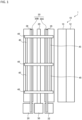
- FIG. 1 is a plan view schematically illustrating an overall arrangement configuration example of a false-twist texturing system 1.
- a yarn feeding package in which a yarn is wound around a cylindrical take-up tube is supplied to a creel stand 30 by a creel robot 50 that moves on a rail 20 extending in a linear shape.
- the creel robot 50 collects an empty take-up tube around which no yarn is wound from the creel stand 30.
- the "yarn" used herein is exemplified by synthetic fibers, such as polyester.
- the "yarn feeding package” is a windingtype package for supplying a yarn (synthetic fiber) used in a manufacturing process, such as a false-twist texturing machine.
- the yarn feeding package is composed of a take-up tube having a cylindrical shape of a center part, and the yarn wound around the take-up tube, and is held by inserting a peg 31B described later (refer to FIG. 3 ) inside the take-up tube.
- the rail 20 corresponds to a "movement passage" used in the present invention.
- the collected empty take-up tube is carried by the creel robot 50 to an empty take-up tube collection box 22 provided, for example, adjacent to the stand body 30A in the longitudinal direction and is collected into the empty take-up tube collection box 22.
- the stand body 30A is configured so that a plurality of column supports 31 extending in a vertical direction and arranged in two rows along the rail 20, and a plurality of partition plates 32 are supported by the column supports 31 at predetermined intervals.
- a peg 31B described below (refer to FIG. 3 ) that supports the take-up tube is provided in the column support 31 near the rail 20 among the plurality of column supports 31.
- FIG. 3 is a view schematically illustrating a configuration of a peg 31B provided in the stand body 30A.
- the column support 31 is provided with a rotary cylinder 31A capable of rotating around the column support 31 in a longitudinal direction of the column support 31 as an axial direction.
- the peg 31B and a claw 31C are provided on the rotary cylinder 31A.
- the peg 31B and the claw 31C rotate integrally as the rotary cylinder 31A rotates.
- the creel robot 50 includes an engagement portion 52 capable of moving in the up-and-down direction, and a peg rotation mechanism 51 that rotates the engagement portion 52.
- the creel robot 50 supplies the yarn feeding package to the creel stand 30, and when the creel robot 50 collects the empty take-up tube from the creel stand 30, the creel robot 50 engages the engagement portion 52 with the claw 31C of the creel stand 30, and, in that state, drives the peg rotation mechanism 51 to rotate the engagement portion 52. Consequently, the claw 31C rotates, and the peg 31B also rotates accordingly.
- the creel robot 50 can supply the yarn feeding package and collect the empty take-up tube.
- the stand bodies 30A, 30B When replacing of the take-up tube, particularly when supplying the yarn feeding packages to the stand bodies 30A, 30B, a reaction force generated when the heavy yarn feeding package is supported by the peg 31B is applied to the stand bodies 30A, 30B.
- the stand bodies 30A, 30B are coupled to each other by the beam mechanism 40 to form a single structure.
- the beam mechanism 40 couples the stand bodies 30A, 30B to each other at an upper position above the creel robot 50 so as not to interfere the movement of the creel robot 50 moving between the stand bodies 30A, 30B.
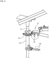
- FIG. 4 is a view of an upper portion of the stand bodies 30A, 30B and the creel robot 50 as viewed from a longitudinal direction of the stand bodies 30A, 30B.
- the beam mechanism 40 includes longitudinal coupling members 41A, 41B, a lateral coupling member 42, and diagonal members 43A, 43B.
- the longitudinal coupling members 41A, 41B and the lateral coupling member 42 correspond to a "coupling rod-like member" used in the present invention.
- the longitudinal coupling member 41A is a long rod-like member, and is fixed to an upper portion of the stand body 30A taking a posture along the vertical direction.
- the longitudinal coupling member 41A is coupled to, for example, the column support 31 of the stand body 30A.
- the longitudinal coupling member 41B is fixed to an upper portion of the stand body 30B.
- the lateral coupling member 42 is a long rod-like member, and couples tip portions of the longitudinal coupling members 41A, 41B to each other.
- the lateral coupling member 42 is coupled to the longitudinal coupling members 41A, 41B at a substantially right angle.
- the longitudinal coupling members 41A, 41B and the lateral coupling member 42 may be coupled to each other using a jig, or may be coupled to each other by welding or the like.
- the longitudinal coupling members 41A, 41B and the lateral coupling member 42 each have a dimensional adjustment mechanism capable of length adjustment.
- the dimensional adjustment mechanism include a mechanism in which a rod member is inserted into a long cylinder and the rod member is advanced or retreated with respect to the cylinder to adjust the length.
- the diagonal members 43A, 43B respectively are diagonally coupled to the longitudinal coupling members 41A, 41B and the lateral coupling member 42 to form a trussed structure.
- a strength of the beam mechanism 40 in a direction orthogonal to the longitudinal direction of the stand bodies 30A, 30B can be increased by providing the diagonal members 43A, 43B.
- a plurality of the beam mechanisms 40 are provided in the longitudinal direction of the stand bodies 30A, 30B (refer to FIGs. 1 and 2 ). Moreover, the beam mechanism 40 is coupled to a connection member 45 extending in the longitudinal direction. Consequently, the beam mechanism 40 can prevent from toppling in the longitudinal direction of the stand bodies 30A, 30B and the strength of the beam mechanism 40 can be increased.
- the creel stand 30 can be into the single structure, and the rigidity of the creel stand 30 can be improved.
- the creel stand 30 includes a long C-shape steel 35 provided at an upper portion of the stand body 30A.
- the C-shape steel 35 corresponds to a "stand engagement mechanism" used in the present invention.
- the C-shape steel 35 extends along a direction parallel to the rail 20, i.e., along the longitudinal direction of the stand body 30A, (refer to FIGs. 1 and 2 ).
- a support plate 36 is provided as to bridge over two column supports 31 aligned in a line in the direction orthogonal to the rail 20.
- a plurality of the support plates 36 are provided in the longitudinal direction of the stand body 30A at predetermined intervals.
- the C-shape steel 35 is supported at a position near the creel robot 50 in the support plate 36 as viewed from the longitudinal direction of the stand body 30A.
- the C-shape steel 35 is provided to take a posture in which an open portion faces upward, as viewed from the longitudinal direction thereof.
- One side surface of the C-shape steel 35, provided in this way, extending in the up-and-down direction corresponds to a "flange" used in the present invention.
- the C-shape steel 35 functions as a guide passage for the creel robot 50.
- the creel robot 50 includes an extension member 53A extending from the upper position thereof toward the stand body 30A.
- the extension member 53A is located at an upper position above the stand body 30A and has a tip portion extending to the position of the C-shape steel 35.
- a pair of rollers 54 are provided at a lower tip portion of the extension member 53A.
- the pair of rollers 54 each rotate around the up-and-down direction as a rotation axis.
- the pair of rollers 54 rotate so as to sandwich one side surface of the C-shape steel 35 therebetween.
- a distance between the creel robot 50 and the stand body 30A is regulated by a length of the extension member 53A. Consequently, even when receiving a reaction force that tips the stand body 30A or the creel robot 50, the distance between the creel robot 50 and the stand body 30A can be maintained constant.
- a support plate 37 is provided so as to bridge over two column supports 31, similarly to the stand body 30A.
- a plurality of the support plates 37 are provided in the longitudinal direction of the stand body 30B at predetermined intervals.
- the long C-shape steel 38 is provided on the plurality of the support plates 37 to take a posture in which an open portion faces upward, as viewed from the longitudinal direction thereof.
- the C-shape steel 38 also functions as a guide passage for the creel robot 50.
- the creel robot 50 includes an extension member 53B extending from the upper position thereof toward the stand body 30B.
- the extension member 53B is located an upper position above the stand body 30B and has a tip portion extending to the position of the C-shape steel 38.
- One roller 55 is provided at a lower tip portion of the extension member 53B.
- the roller 55 rotates around the up-and-down direction as a rotation axis. This roller 55 is provided between both side surfaces of the C-shape steel 38 and rotates while being in contact with the both side surfaces.
- the creel stand 30 of the present embodiment is configured as the single structure formed by coupling the stand bodies 30A, 30B, arranged to be separated from each other, by the beam mechanism 40. Therefore, high rigidity can be obtained compared with a case where the stand bodies 30A, 30B are arranged independently from each other. Moreover, for example, even when a reaction force generated when the heavy yarn feeding package is supplied from the creel robot 50 to the peg 31B of the stand body 30A is applied to the stand body 30A, the reaction force is distributed to the stand body 30B through the beam mechanism 40, thereby reducing swaying and tilting.
- the stand bodies 30A, 30B arranged to be separated from each other are coupled to each other by the beam mechanism 40, it is possible to prevent each of the stand bodies 30A, 30B from tipping.
- the stand bodies 30A, 30B by connecting one of the stand bodies 30A, 30B to a wall or ceiling of a factory, swaying, tilting, or tipping can further be suppressed. Such advantageous effects become more pronounced as the height of the stand bodies 30A, 30B increases.
- the distance between the stand bodies 30A, 30B and the creel robot 50 is maintainable at a constant distance by reducing tilt of the stand bodies 30A, 30B, it becomes possible for the creel robot 50 to supply the yarn feeding package to the stand bodies 30A, 30B with high reliability.
- the plurality of beam mechanisms 40 are provided in the longitudinal direction of the stand bodies 30A, 30B, it is possible to further reduce swaying and tilting of the stand bodies 30A, 30B. Consequently, it becomes possible for the creel robot 50 to supply the yarn feeding package to the stand bodies 30A, 30B with high reliability.
- the lengths of the longitudinal coupling members 41A, 41B and the lateral coupling member 42 of the beam mechanism 40 it can be adjusted in accordance with a distance between the stand bodies 30A, 30B when attaching the beam mechanism 40 to the stand bodies 30A, 30B. Furthermore, since the length of the longitudinal coupling members 41A, 41B can be adjusted, the lateral coupling member 42 can be attached closely to, for example, a beam, ceiling, or the like of the factory, and swaying or tipping of the stand bodies 30A, 30B can be prevented.
- the beam mechanism 40 is configured of the plurality of members, but may be configured of merely one member.
- the column support 31 may be lengthened and an upper portion of the lengthened column support 31 may be used as the longitudinal coupling member 41A.
- the dimensional adjustment mechanism for the beam mechanism 40 may be a mechanism in which a plurality of small rod members are coupled to form one long rod member and the length is adjusted by adjusting the number of small rod members.
- the stand bodies 30A, 30B may be coupled to each other only by a lateral coupling member 42 without using the longitudinal coupling members 41A, 41B.
- the beam mechanism 40 couples the stand bodies 30A, 30B along a direction orthogonal to the longitudinal direction of the stand bodies 30A, 30B, but the beam mechanism 40 may couple them along a direction of diagonally intersecting with respect to the longitudinal direction, for example.
- the C-shape steel 35 which is a stand engagement mechanism is provided in the upper portion of the stand body 30A and the one side surface of the C-shape steel is sandwiched by the pair of rollers 54 provided at the lower tip portion of the extension member 53A, but it is not limited to such an example.
- a C-shape steel may be provided near a center of the stand body 30A in the up-and-down direction taking a posture in which an open portion faces the creel robot 50 side, and a member may be provided extending from the tip of the extension member 53A to the C-shape steel toward a vertically lower side, so that the C-shape steel is sandwiched by the pair of rollers. Even in this case, the distance between the stand body 30A and the creel robot 50 can be maintained constant.
- the stand engagement mechanism may be provided on each of the stand bodies 30A, 30B.
- the pair of rollers 54 provided at the lower tip portion of the extension member 53A is capable of rotating in a state where the one side surface of the C-shape steel 35 is sandwiched therebetween, but in addition there to, a load of the creel robot 50 may be applied to a web of the C-shape steel 35.
- a load of the creel robot 50 may be applied to a web of the C-shape steel 35.
- the creel robot 50 When the load of the creel robot 50 can be applied to the web of the C-shape steel 35, the creel robot 50 will lean against the stand body 30A, and the weight of the creel robot 50 can make the stand body 30A more stable. Moreover, by stabilizing the stand body 30A, it is possible to also stabilize the stand body 30B coupled to the stand body 30A by the beam mechanism 40.
- the extension members 53A, 53B are provided extending toward both of the pair of stand bodies 30A, 30B from the upper position of the creel robot 50, but it is not limited to this example.
- the extension member (53A or 53B) may be provided extending from the upper position of the creel robot 50 toward only any one of the pair of stand bodies 30A, 30B.
- the C-shape steel (35 or 38) at the upper portion of the stand body (30A or 30B) on the side having the extension member, so as to rotate the pair of rollers 54 provided at the lower tip portion of the extension member in the state where the one side surface of the C-shape steel (35 or 38) is sandwiched therebetween.
- the pair of rollers 54 are configured to rotate with one side surface of the C-shape steel 35 sandwiched therebetween, but the member is not limited to such a C-shape steel and may be any member (e.g., an L-shape steel) including a flange that can be sandwiched between the pair of rollers 54.
- the member is not limited to such a C-shape steel and may be any member (e.g., an L-shape steel) including a flange that can be sandwiched between the pair of rollers 54.
Landscapes
- Unwinding Of Filamentary Materials (AREA)
- Replacing, Conveying, And Pick-Finding For Filamentary Materials (AREA)
Abstract
Description
- The present invention relates to a creel stand.
- Regarding a technology of a creel stand in which a yarn feeding package is supplied by a creel robot, Patent document 1 discloses a technology in which a pair of creel stands capable of holding a plurality of yarn feeding packages are arranged opposite each other across a passage along which a self-propelled yarn feeding package changer travels. In the technology disclosed in Patent Document 1, the yarn feeding package changer rotates 180 degrees by rotating device, an operation of changing the empty take-up tube and the yarn feeding package can be performed also in any of the creel stands arranged opposite each other.
- Patent Document 1:
Japanese Patent Application Publication No. H09-194139 - Incidentally, when a yarn feeding package is supplied to a creel stand by a creel robot, a reaction force when moving the yarn feeding package, which is a heavy load, to the creel stand from the creel robot acts on the creel stand, easily causing the creel stand to sway and tilt significantly. Consequently, there is room for an improvement in that a distance between the creel stand and the creel robot becomes unstable, making it difficult for the creel robot to supply the yarn feeding package. In particular, in recent years, the height of creel stands has tended to be higher than in the past, which has resulted in significant swaying and tilting of the creel stands.
- The present invention has been made in view of the above-described technical problems, and an object thereof is to provide a creel stand that enables a creel robot to supply a yarn feeding package with high reliability.
- A first aspect of the present invention is
a creel stand in which a yarn feeding package to a peg is supplied by a creel robot, the creel stand comprising: - a pair of stand bodies arranged on both sides sandwiching a movement passage along which the creel robot moves and configured to support the peg; and
- a beam mechanism configured to couple the pair of stand bodies at an upper position above the creel robot, wherein
- at least one stand body among the pair of stand bodies includes a stand engagement mechanism engaged with an extension member extending in a direction of the one stand body from the upper position of the creel robot along a direction parallel to the movement passage of the creel robot.
- According to the above-described first aspect of the creel stand, due to the portions being coupled to each other by the beam mechanism at an upper position above the creel robot in the stand body, the pair of stand bodies have high rigidity as a single structure. Consequently, even when a reaction force generated when the creel robot supplies the yarn feeding package to the peg of one stand body is applied to the stand body, sway and tilt of the stand body is reduced by the high rigidity of stand bodies and dispersion of the reaction force to the other stand body via the beam mechanism. Moreover, since tilt of the stand body is reduced, a distance between the one stand body and the other stand body and a distance between the creel robot and the stand body are each constantly maintained. Accordingly, it becomes possible for the creel robot to supply the yarn feeding package to the peg with high reliability.
- Moreover, in the high rigid structure in which the stand bodies are coupled to each other by the beam mechanism, the creel robot travels and stops along the stand body in the state where the extension member and the stand engagement mechanism are engaged with each other. Accordingly, even when the number of arranged pegs on the stand body increases and the creel stand and/or the creel robot become taller and become easy to cause tilt and sway, the distance between the stand body and the creel robot can always be maintained constant. Consequently, it becomes possible for the creel robot to supply the yarn feeding package to the peg with high reliability.
- A second aspect of the present invention is the creel stand in the above-described first aspect, wherein preferably the stand engagement mechanism is a rail including a flange longitudinally provided in an up-and-down direction, wherein
the flange is sandwiched with at least two rollers provided rotatably around a rotation axis in the up-and-down direction provided on the extension member. - According to the above-described second aspect of the creel stand, the flange longitudinally provided in the up-and-down direction is sandwiched with the rollers provided rotatably around the rotation axis in the up-and-down direction provided on the extension member. Accordingly, the distance between the creel robot and the stand body is regulated by the length of the extension member. Consequently, even when receiving a reaction force that tips the stand body and/or the creel robot, the distance between the creel robot and the stand body can be maintained constant.
- A third aspect of the present invention is the creel stand in the above-described first or second aspect, wherein preferably
- the beam mechanism includes a coupling rod-like member coupling the pair of stand bodies to each other, and
- the coupling rod-like member includes a dimensional adjustment mechanism capable of adjusting a length dimension in an axial direction.
- According to the above-described third aspect of the creel stand, when the beam mechanism is attached to the stand body, the distance between the pair of stand bodies can be finely adjusted by the dimensional adjustment mechanism.
- A fourth aspect of the present invention is the creel stand in the above-described preceding aspects, wherein preferably a plurality of the beam mechanisms are arranged in a longitudinal direction of the stand body.
- According to the above-described fourth aspect of the creel stand, since the plurality of the beam mechanisms are arranged in the longitudinal direction of the stand body and therefore higher rigidity can be obtained as the structure in which the stand bodies are coupled to each other by the plurality of beam mechanisms, sway and tilt of the stand body can further be reduced. Consequently, it becomes possible for the creel robot to supply the yarn feeding package to the peg with high reliability.
- A fifth aspect of the present invention is the creel stand in the above-described preceding aspects, wherein preferably the beam mechanism includes a diagonal member forming a trussed structure.
- According to the above-described fifth aspect of the creel stand, since the beam mechanism includes the diagonal member forming the trussed structure and therefore higher rigidity can be obtained as the structure in which the stand bodies are coupled to each other by the beam mechanisms, sway and tilt of the stand body can further be reduced. Consequently, it becomes possible for the creel robot to supply the yarn feeding package to the peg with high reliability.
- The creel stand according to the present invention may be formed of merely the configuration described as the creel stand described in the above-described first aspect, or may be formed of freely combining the configuration described in the above-described first aspect with the configuration(s) described in any of the above-described second to fifth aspects, to the extent that consistency can be achieved. When combining the configuration described in the above-described first aspect with the configuration(s) described in any of the above-described second to fifth aspects, all or part of the configuration described in the above-described first aspect can be combined with all or part of configurations of described in the above-described second to fifth aspects, to the extent that consistency can be achieved.
- According to the present invention, it is possible to provide a creel stand that enables a creel robot to supply a yarn feeding package with high reliability.
-
-
FIG. 1 is a plan view schematically illustrating an overall arrangement configuration example of a false-twist texturing system. -
FIG. 2 is an example of a perspective diagram schematically illustrating the false-twist texturing system. -
FIG. 3 is a view schematically illustrating a configuration of a peg provided in the stand body. -
FIG. 4 is a view of an upper portion of the stand bodies and a creel robot as viewed from a longitudinal direction of the stand bodies. - Hereinafter, embodiments for carrying out the present invention will be described with reference to the drawings.
-
FIG. 1 is a plan view schematically illustrating an overall arrangement configuration example of a false-twist texturing system 1. In a false-twist texturing system 1, a yarn feeding package in which a yarn is wound around a cylindrical take-up tube is supplied to acreel stand 30 by acreel robot 50 that moves on arail 20 extending in a linear shape. Moreover, when supplying the yarn feeding package to thecreel stand 30, thecreel robot 50 collects an empty take-up tube around which no yarn is wound from thecreel stand 30. The "yarn" used herein is exemplified by synthetic fibers, such as polyester. The "yarn feeding package" is a windingtype package for supplying a yarn (synthetic fiber) used in a manufacturing process, such as a false-twist texturing machine. The yarn feeding package is composed of a take-up tube having a cylindrical shape of a center part, and the yarn wound around the take-up tube, and is held by inserting apeg 31B described later (refer toFIG. 3 ) inside the take-up tube. Therail 20 corresponds to a "movement passage" used in the present invention. - The
creel stand 30 includes a pair ofstand bodies rail 20 and coupled to each other by thebeam mechanism 40. A rawyarn storage unit 26 is provided at a position adjacent to thestand body 30B in a longitudinal direction. The yarn feeding packages to be supplied to thestand bodies yarn storage unit 26 and are temporarily stored in the rawyarn storage unit 26. Then, the yarn feeding packages stored therein are removed from the rawyarn storage unit 26 by thecreel robot 50 and are carried to thecreel stand 30. - A
machine base 10 is provided at a position, which is adjacent to thestand body 30A and an opposite side to therail 20. Although not illustrated, a machine base is provided adjacent also to thestand body 30B. Themachine base 10 mainly includes, for example, a false-twist texturing machine 12 and a windingmachine 14. The yarn unwound from the yarn feeding package is supplied from the creel stand 30 to the false-twist texturing machine 12. In the false-twist texturing machine 12, the yarn unwound from the yarn feeding package is false-twisted. The false-twisted yarn is wound by the windingmachine 14. - The empty take-up tube around which no yarn is wound, obtained by unwinding all the yarn from the yarn feeding package, is collected by the
creel robot 50 from thecreel stand 30. The collected empty take-up tube is carried by thecreel robot 50 to an empty take-uptube collection box 22 provided, for example, adjacent to thestand body 30A in the longitudinal direction and is collected into the empty take-uptube collection box 22. -
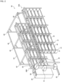
FIG. 2 is an example of a perspective diagram schematically illustrating the false-twist texturing system 1.FIG. 2 omits illustration of the false-twist texturing machine 12, the windingmachine 14, and the empty take-uptube collection box 22, which are illustrated withFIG. 1 . Since thestand bodies stand body 30A is mainly described below, and a detailed description of thestand body 30B configuration is omitted. - The
stand body 30A is configured so that a plurality of column supports 31 extending in a vertical direction and arranged in two rows along therail 20, and a plurality ofpartition plates 32 are supported by the column supports 31 at predetermined intervals. Apeg 31B described below (refer toFIG. 3 ) that supports the take-up tube is provided in thecolumn support 31 near therail 20 among the plurality of column supports 31. -
FIG. 3 is a view schematically illustrating a configuration of apeg 31B provided in thestand body 30A. - The
column support 31 is provided with arotary cylinder 31A capable of rotating around thecolumn support 31 in a longitudinal direction of thecolumn support 31 as an axial direction. Thepeg 31B and aclaw 31C are provided on therotary cylinder 31A. Thepeg 31B and theclaw 31C rotate integrally as therotary cylinder 31A rotates. - Although a detailed description of the configuration of the
creel robot 50 is omitted, thecreel robot 50 includes anengagement portion 52 capable of moving in the up-and-down direction, and apeg rotation mechanism 51 that rotates theengagement portion 52. When thecreel robot 50 supplies the yarn feeding package to thecreel stand 30, and when thecreel robot 50 collects the empty take-up tube from thecreel stand 30, thecreel robot 50 engages theengagement portion 52 with theclaw 31C of thecreel stand 30, and, in that state, drives thepeg rotation mechanism 51 to rotate theengagement portion 52. Consequently, theclaw 31C rotates, and thepeg 31B also rotates accordingly. By rotating thepeg 31B to be directed to thecreel robot 50 side, thecreel robot 50 can supply the yarn feeding package and collect the empty take-up tube. - When replacing of the take-up tube, particularly when supplying the yarn feeding packages to the
stand bodies peg 31B is applied to thestand bodies stand bodies stand bodies beam mechanism 40 to form a single structure. Thebeam mechanism 40 couples thestand bodies creel robot 50 so as not to interfere the movement of thecreel robot 50 moving between thestand bodies -
FIG. 4 is a view of an upper portion of thestand bodies creel robot 50 as viewed from a longitudinal direction of thestand bodies - The
beam mechanism 40 includeslongitudinal coupling members lateral coupling member 42, anddiagonal members longitudinal coupling members lateral coupling member 42 correspond to a "coupling rod-like member" used in the present invention. - The
longitudinal coupling member 41A is a long rod-like member, and is fixed to an upper portion of thestand body 30A taking a posture along the vertical direction. Thelongitudinal coupling member 41A is coupled to, for example, thecolumn support 31 of thestand body 30A. Thelongitudinal coupling member 41B is fixed to an upper portion of thestand body 30B. - The
lateral coupling member 42 is a long rod-like member, and couples tip portions of thelongitudinal coupling members lateral coupling member 42 is coupled to thelongitudinal coupling members longitudinal coupling members lateral coupling member 42 may be coupled to each other using a jig, or may be coupled to each other by welding or the like. - The
longitudinal coupling members lateral coupling member 42 each have a dimensional adjustment mechanism capable of length adjustment. Examples of the dimensional adjustment mechanism include a mechanism in which a rod member is inserted into a long cylinder and the rod member is advanced or retreated with respect to the cylinder to adjust the length. - The
diagonal members longitudinal coupling members lateral coupling member 42 to form a trussed structure. A strength of thebeam mechanism 40 in a direction orthogonal to the longitudinal direction of thestand bodies diagonal members - A plurality of the
beam mechanisms 40 are provided in the longitudinal direction of thestand bodies FIGs. 1 and2 ). Moreover, thebeam mechanism 40 is coupled to aconnection member 45 extending in the longitudinal direction. Consequently, thebeam mechanism 40 can prevent from toppling in the longitudinal direction of thestand bodies beam mechanism 40 can be increased. - Thus, by coupling the
stand bodies beam mechanism 40, the creel stand 30 can be into the single structure, and the rigidity of the creel stand 30 can be improved. - The creel stand 30 includes a long C-
shape steel 35 provided at an upper portion of thestand body 30A. The C-shape steel 35 corresponds to a "stand engagement mechanism" used in the present invention. The C-shape steel 35 extends along a direction parallel to therail 20, i.e., along the longitudinal direction of thestand body 30A, (refer toFIGs. 1 and2 ). - At an upper portion of the
stand body 30A, asupport plate 36 is provided as to bridge over two column supports 31 aligned in a line in the direction orthogonal to therail 20. A plurality of thesupport plates 36 are provided in the longitudinal direction of thestand body 30A at predetermined intervals. The C-shape steel 35 is supported at a position near thecreel robot 50 in thesupport plate 36 as viewed from the longitudinal direction of thestand body 30A. The C-shape steel 35 is provided to take a posture in which an open portion faces upward, as viewed from the longitudinal direction thereof. One side surface of the C-shape steel 35, provided in this way, extending in the up-and-down direction corresponds to a "flange" used in the present invention. - The C-
shape steel 35 functions as a guide passage for thecreel robot 50. As illustrated inFIG. 4 , thecreel robot 50 includes anextension member 53A extending from the upper position thereof toward thestand body 30A. Theextension member 53A is located at an upper position above thestand body 30A and has a tip portion extending to the position of the C-shape steel 35. A pair ofrollers 54 are provided at a lower tip portion of theextension member 53A. The pair ofrollers 54 each rotate around the up-and-down direction as a rotation axis. The pair ofrollers 54 rotate so as to sandwich one side surface of the C-shape steel 35 therebetween. - By sandwiching the one side surface of the C-
shape steel 35 between the pair ofrollers 54 of thecreel robot 50, a distance between thecreel robot 50 and thestand body 30A is regulated by a length of theextension member 53A. Consequently, even when receiving a reaction force that tips thestand body 30A or thecreel robot 50, the distance between thecreel robot 50 and thestand body 30A can be maintained constant. - Also at an upper portion of the
stand body 30B, asupport plate 37 is provided so as to bridge over two column supports 31, similarly to thestand body 30A. A plurality of thesupport plates 37 are provided in the longitudinal direction of thestand body 30B at predetermined intervals. The long C-shape steel 38 is provided on the plurality of thesupport plates 37 to take a posture in which an open portion faces upward, as viewed from the longitudinal direction thereof. The C-shape steel 38 also functions as a guide passage for thecreel robot 50. - The
creel robot 50 includes anextension member 53B extending from the upper position thereof toward thestand body 30B. Theextension member 53B is located an upper position above thestand body 30B and has a tip portion extending to the position of the C-shape steel 38. Oneroller 55 is provided at a lower tip portion of theextension member 53B. Theroller 55 rotates around the up-and-down direction as a rotation axis. Thisroller 55 is provided between both side surfaces of the C-shape steel 38 and rotates while being in contact with the both side surfaces. - As described above, the creel stand 30 of the present embodiment is configured as the single structure formed by coupling the
stand bodies beam mechanism 40. Therefore, high rigidity can be obtained compared with a case where thestand bodies creel robot 50 to thepeg 31B of thestand body 30A is applied to thestand body 30A, the reaction force is distributed to thestand body 30B through thebeam mechanism 40, thereby reducing swaying and tilting. Furthermore, thestand bodies beam mechanism 40, it is possible to prevent each of thestand bodies stand bodies stand bodies - Moreover, since the distance between the
stand bodies creel robot 50 is maintainable at a constant distance by reducing tilt of thestand bodies creel robot 50 to supply the yarn feeding package to thestand bodies - Furthermore, since the plurality of
beam mechanisms 40 are provided in the longitudinal direction of thestand bodies stand bodies creel robot 50 to supply the yarn feeding package to thestand bodies - Moreover, since it is possible to adjust the lengths of the
longitudinal coupling members lateral coupling member 42 of thebeam mechanism 40, it can be adjusted in accordance with a distance between thestand bodies beam mechanism 40 to thestand bodies longitudinal coupling members lateral coupling member 42 can be attached closely to, for example, a beam, ceiling, or the like of the factory, and swaying or tipping of thestand bodies - While this embodiment of the present invention has been described above, the present invention is not limited to the above-described embodiment but can be changed in various ways within a scope recited in the claims. For example, in the above-described embodiment, the
beam mechanism 40 is configured of the plurality of members, but may be configured of merely one member. Moreover, thecolumn support 31 may be lengthened and an upper portion of the lengthenedcolumn support 31 may be used as thelongitudinal coupling member 41A. Moreover, the dimensional adjustment mechanism for thebeam mechanism 40 may be a mechanism in which a plurality of small rod members are coupled to form one long rod member and the length is adjusted by adjusting the number of small rod members. Furthermore, as long as the movement of thecreel robot 50 is not hindered, thestand bodies lateral coupling member 42 without using thelongitudinal coupling members - Moreover, in the above-described embodiment, the
beam mechanism 40 couples thestand bodies stand bodies beam mechanism 40 may couple them along a direction of diagonally intersecting with respect to the longitudinal direction, for example. - Furthermore, the C-
shape steel 35 which is a stand engagement mechanism is provided in the upper portion of thestand body 30A and the one side surface of the C-shape steel is sandwiched by the pair ofrollers 54 provided at the lower tip portion of theextension member 53A, but it is not limited to such an example. For example, a C-shape steel may be provided near a center of thestand body 30A in the up-and-down direction taking a posture in which an open portion faces thecreel robot 50 side, and a member may be provided extending from the tip of theextension member 53A to the C-shape steel toward a vertically lower side, so that the C-shape steel is sandwiched by the pair of rollers. Even in this case, the distance between thestand body 30A and thecreel robot 50 can be maintained constant. Moreover, the stand engagement mechanism may be provided on each of thestand bodies - Moreover, in the above-described embodiment, the pair of
rollers 54 provided at the lower tip portion of theextension member 53A is capable of rotating in a state where the one side surface of the C-shape steel 35 is sandwiched therebetween, but in addition there to, a load of thecreel robot 50 may be applied to a web of the C-shape steel 35. By providing, for example, a roller between theroller 54 on the side opposite to the web of the C-shape steel among the pair ofrollers 54 and the web, so as to enable to slide between theroller 54 and the web, the load of thecreel robot 50 can be applied to the web of the C-shape steel 35. When the load of thecreel robot 50 can be applied to the web of the C-shape steel 35, thecreel robot 50 will lean against thestand body 30A, and the weight of thecreel robot 50 can make the standbody 30A more stable. Moreover, by stabilizing thestand body 30A, it is possible to also stabilize thestand body 30B coupled to thestand body 30A by thebeam mechanism 40. - Moreover, in the above-described embodiment, the
extension members stand bodies creel robot 50, but it is not limited to this example. For example, only the extension member (53A or 53B) may be provided extending from the upper position of thecreel robot 50 toward only any one of the pair ofstand bodies rollers 54 provided at the lower tip portion of the extension member in the state where the one side surface of the C-shape steel (35 or 38) is sandwiched therebetween. - Moreover, in the above-described embodiment, the pair of
rollers 54 are configured to rotate with one side surface of the C-shape steel 35 sandwiched therebetween, but the member is not limited to such a C-shape steel and may be any member (e.g., an L-shape steel) including a flange that can be sandwiched between the pair ofrollers 54. -
- 20 Rail
- 30 Creel stand
- 30A, 30B Stand body
- 35, 38 C-shape steel
- 40 Beam mechanism
- 41A, 41B Longitudinal coupling member
- 42 Lateral coupling member
- 50 Creel robot
- 53A,53B Extension member
- 54, 55 Roller
Claims (3)
- A creel stand (30) in which a yarn feeding package to a peg (31B) is supplied by a creel robot (50), the creel stand (30) comprising:a pair of stand bodies (30A or 30B) arranged on both sides sandwiching a movement passage along which the creel robot (50) moves and configured to support the peg (31B); anda beam mechanism (40) configured to couple the pair of stand bodies (30A or 30B) at an upper position above the creel robot (50), whereinat least one stand body (30A and 30B) among the pair of stand bodies (30A or 30B) includes a stand engagement mechanism (C-shape steel 35) engaged with an extension member (53A, 53B) extending in a direction of the one stand body (30A or 30B) from the upper position of the creel robot (50) along a direction parallel to the movement passage of the creel robot (50).
- The creel stand (30) as claimed in claim 1, whereinthe stand engagement mechanism (C-shape steel 35) is a rail which includes a flange (one side surface extending in an up-and-down direction of the C-shape steel 35) longitudinally provided in the up-and-down direction, whereinthe flange is sandwiched with at least two rollers (54) provided rotatably around a rotation axis in the up-and-down direction provided on the extension member (53A, 53B).
- The creel stand (30) as claimed in claim 1 or 2, whereinthe beam mechanism (40) includes a coupling rod-like member (longitudinal coupling members 41A, 41B and a lateral coupling member 42) coupling the pair of stand bodies (30A or 30B) to each other, andthe coupling rod-like member (the longitudinal coupling members 41A, 41B and the lateral coupling member 42) includes a dimensional adjustment mechanism capable of adjusting a length dimension in an axial direction.
Applications Claiming Priority (1)
| Application Number | Priority Date | Filing Date | Title |
|---|---|---|---|
| JP2023179609A JP2025069714A (en) | 2023-10-18 | 2023-10-18 | Creel Stand |
Publications (2)
| Publication Number | Publication Date |
|---|---|
| EP4541744A1 true EP4541744A1 (en) | 2025-04-23 |
| EP4541744B1 EP4541744B1 (en) | 2026-08-19 |
Family
ID=92973415
Family Applications (1)
| Application Number | Title | Priority Date | Filing Date |
|---|---|---|---|
| EP24204214.1A Active EP4541744B1 (en) | 2023-10-18 | 2024-10-02 | Creel stand |
Country Status (4)
| Country | Link |
|---|---|
| EP (1) | EP4541744B1 (en) |
| JP (1) | JP2025069714A (en) |
| CN (1) | CN119873509A (en) |
| TW (1) | TW202517560A (en) |
Citations (3)
| Publication number | Priority date | Publication date | Assignee | Title |
|---|---|---|---|---|
| US4783021A (en) * | 1986-01-27 | 1988-11-08 | Murata Kikai Kabushiki Kaisha | Apparatus for supplying packages to a creel |
| JPH09194139A (en) | 1996-01-11 | 1997-07-29 | Murata Mach Ltd | Yarn feeding system |
| CN110817212A (en) * | 2019-12-17 | 2020-02-21 | 成都瑞克西工业自动化技术有限公司 | Automatic zipper dyeing production line |
-
2023
- 2023-10-18 JP JP2023179609A patent/JP2025069714A/en active Pending
-
2024
- 2024-09-29 CN CN202411368055.8A patent/CN119873509A/en active Pending
- 2024-10-02 EP EP24204214.1A patent/EP4541744B1/en active Active
- 2024-10-08 TW TW113138171A patent/TW202517560A/en unknown
Patent Citations (3)
| Publication number | Priority date | Publication date | Assignee | Title |
|---|---|---|---|---|
| US4783021A (en) * | 1986-01-27 | 1988-11-08 | Murata Kikai Kabushiki Kaisha | Apparatus for supplying packages to a creel |
| JPH09194139A (en) | 1996-01-11 | 1997-07-29 | Murata Mach Ltd | Yarn feeding system |
| CN110817212A (en) * | 2019-12-17 | 2020-02-21 | 成都瑞克西工业自动化技术有限公司 | Automatic zipper dyeing production line |
Also Published As
| Publication number | Publication date |
|---|---|
| CN119873509A (en) | 2025-04-25 |
| TW202517560A (en) | 2025-05-01 |
| EP4541744B1 (en) | 2026-08-19 |
| JP2025069714A (en) | 2025-05-01 |
Similar Documents
| Publication | Publication Date | Title |
|---|---|---|
| EP1379461B1 (en) | Unwinder and method for unwinding elastomeric fiber | |
| EP0902114B1 (en) | Formation stabilizing guide for braider | |
| CN102674075B (en) | Spinning take-up machine | |
| JP5864338B2 (en) | Spinning and winding device and spinning and winding equipment | |
| EP1980518A1 (en) | Yarn traverse guide | |
| RU2061120C1 (en) | Spindleless spinning machine | |
| KR100337250B1 (en) | Roller Board for Organizing Filaments, System for Delivering Filaments and Method for Threading Filaments | |
| EP0567497A1 (en) | Yarn delivery. | |
| JP2025069714A (en) | Creel Stand | |
| US4512373A (en) | Feeding and guiding means for triaxial fabric forming machine | |
| CN218115751U (en) | Electronic weft accumulator for active weft feeding | |
| JP3037983B2 (en) | Textile processing machine | |
| US3432118A (en) | Creel | |
| CN102234855A (en) | Spinning machine | |
| CN118619009A (en) | System for loading yarn packages onto creel assemblies | |
| CN221439988U (en) | Yarn separating device and yarn feeding equipment with same | |
| JPH08151169A (en) | Multiple yarn stand | |
| EP4541743A1 (en) | Creel robot | |
| EP0434630A2 (en) | A method for exchanging roving bobbins applied to a ring spinning frame | |
| JP2700581B2 (en) | Roving yarn guide in spinning machine | |
| JPH0336533Y2 (en) | ||
| CN222412078U (en) | Yarn doubling system and warping machine | |
| JPH0413464B2 (en) | ||
| JPH07133521A (en) | Bobbin carriage | |
| EP4541747A1 (en) | Take-up tube collection system and take-up tube collection apparatus |
Legal Events
| Date | Code | Title | Description |
|---|---|---|---|
| PUAI | Public reference made under article 153(3) epc to a published international application that has entered the european phase |
Free format text: ORIGINAL CODE: 0009012 |
|
| STAA | Information on the status of an ep patent application or granted ep patent |
Free format text: STATUS: THE APPLICATION HAS BEEN PUBLISHED |
|
| AK | Designated contracting states |
Kind code of ref document: A1 Designated state(s): AL AT BE BG CH CY CZ DE DK EE ES FI FR GB GR HR HU IE IS IT LI LT LU LV MC ME MK MT NL NO PL PT RO RS SE SI SK SM TR |
|
| STAA | Information on the status of an ep patent application or granted ep patent |
Free format text: STATUS: REQUEST FOR EXAMINATION WAS MADE |
|
| 17P | Request for examination filed |
Effective date: 20250605 |
|
| STAA | Information on the status of an ep patent application or granted ep patent |
Free format text: STATUS: EXAMINATION IS IN PROGRESS |
|
| 17Q | First examination report despatched |
Effective date: 20251007 |
|
| GRAP | Despatch of communication of intention to grant a patent |
Free format text: ORIGINAL CODE: EPIDOSNIGR1 |
|
| STAA | Information on the status of an ep patent application or granted ep patent |
Free format text: STATUS: GRANT OF PATENT IS INTENDED |
|
| INTG | Intention to grant announced |
Effective date: 20260521 |
|
| GRAS | Grant fee paid |
Free format text: ORIGINAL CODE: EPIDOSNIGR3 |
|
| GRAA | (expected) grant |
Free format text: ORIGINAL CODE: 0009210 |
|
| STAA | Information on the status of an ep patent application or granted ep patent |
Free format text: STATUS: THE PATENT HAS BEEN GRANTED |
|
| P01 | Opt-out of the competence of the unified patent court (upc) registered |
Free format text: CASE NUMBER: UPC_APP_0021112_4541744/2026 Effective date: 20260707 |