EP4541603A1 - Motorcycle tire - Google Patents
Motorcycle tire Download PDFInfo
- Publication number
- EP4541603A1 EP4541603A1 EP24199841.8A EP24199841A EP4541603A1 EP 4541603 A1 EP4541603 A1 EP 4541603A1 EP 24199841 A EP24199841 A EP 24199841A EP 4541603 A1 EP4541603 A1 EP 4541603A1
- Authority
- EP
- European Patent Office
- Prior art keywords
- zone
- land ratio
- contacting surface
- tread
- ground contacting
- Prior art date
- Legal status (The legal status is an assumption and is not a legal conclusion. Google has not performed a legal analysis and makes no representation as to the accuracy of the status listed.)
- Pending
Links
Images


Classifications
-
- B—PERFORMING OPERATIONS; TRANSPORTING
- B60—VEHICLES IN GENERAL
- B60C—VEHICLE TYRES; TYRE INFLATION; TYRE CHANGING; CONNECTING VALVES TO INFLATABLE ELASTIC BODIES IN GENERAL; DEVICES OR ARRANGEMENTS RELATED TO TYRES
- B60C11/00—Tyre tread bands; Tread patterns; Anti-skid inserts
- B60C11/03—Tread patterns
- B60C11/0327—Tread patterns characterised by special properties of the tread pattern
- B60C11/033—Tread patterns characterised by special properties of the tread pattern by the void or net-to-gross ratios of the patterns
-
- B—PERFORMING OPERATIONS; TRANSPORTING
- B60—VEHICLES IN GENERAL
- B60C—VEHICLE TYRES; TYRE INFLATION; TYRE CHANGING; CONNECTING VALVES TO INFLATABLE ELASTIC BODIES IN GENERAL; DEVICES OR ARRANGEMENTS RELATED TO TYRES
- B60C11/00—Tyre tread bands; Tread patterns; Anti-skid inserts
- B60C11/0041—Tyre tread bands; Tread patterns; Anti-skid inserts comprising different tread rubber layers
-
- B—PERFORMING OPERATIONS; TRANSPORTING
- B60—VEHICLES IN GENERAL
- B60C—VEHICLE TYRES; TYRE INFLATION; TYRE CHANGING; CONNECTING VALVES TO INFLATABLE ELASTIC BODIES IN GENERAL; DEVICES OR ARRANGEMENTS RELATED TO TYRES
- B60C11/00—Tyre tread bands; Tread patterns; Anti-skid inserts
- B60C11/03—Tread patterns
-
- B—PERFORMING OPERATIONS; TRANSPORTING
- B60—VEHICLES IN GENERAL
- B60C—VEHICLE TYRES; TYRE INFLATION; TYRE CHANGING; CONNECTING VALVES TO INFLATABLE ELASTIC BODIES IN GENERAL; DEVICES OR ARRANGEMENTS RELATED TO TYRES
- B60C1/00—Tyres characterised by the chemical composition or the physical arrangement or mixture of the composition
- B60C1/0016—Compositions of the tread
-
- B—PERFORMING OPERATIONS; TRANSPORTING
- B60—VEHICLES IN GENERAL
- B60C—VEHICLE TYRES; TYRE INFLATION; TYRE CHANGING; CONNECTING VALVES TO INFLATABLE ELASTIC BODIES IN GENERAL; DEVICES OR ARRANGEMENTS RELATED TO TYRES
- B60C11/00—Tyre tread bands; Tread patterns; Anti-skid inserts
- B60C11/03—Tread patterns
- B60C11/0302—Tread patterns directional pattern, i.e. with main rolling direction
-
- B—PERFORMING OPERATIONS; TRANSPORTING
- B60—VEHICLES IN GENERAL
- B60C—VEHICLE TYRES; TYRE INFLATION; TYRE CHANGING; CONNECTING VALVES TO INFLATABLE ELASTIC BODIES IN GENERAL; DEVICES OR ARRANGEMENTS RELATED TO TYRES
- B60C11/00—Tyre tread bands; Tread patterns; Anti-skid inserts
- B60C11/03—Tread patterns
- B60C11/032—Patterns comprising isolated recesses
-
- B—PERFORMING OPERATIONS; TRANSPORTING
- B60—VEHICLES IN GENERAL
- B60C—VEHICLE TYRES; TYRE INFLATION; TYRE CHANGING; CONNECTING VALVES TO INFLATABLE ELASTIC BODIES IN GENERAL; DEVICES OR ARRANGEMENTS RELATED TO TYRES
- B60C11/00—Tyre tread bands; Tread patterns; Anti-skid inserts
- B60C11/03—Tread patterns
- B60C11/04—Tread patterns in which the raised area of the pattern consists only of continuous circumferential ribs, e.g. zig-zag
-
- B—PERFORMING OPERATIONS; TRANSPORTING
- B60—VEHICLES IN GENERAL
- B60C—VEHICLE TYRES; TYRE INFLATION; TYRE CHANGING; CONNECTING VALVES TO INFLATABLE ELASTIC BODIES IN GENERAL; DEVICES OR ARRANGEMENTS RELATED TO TYRES
- B60C11/00—Tyre tread bands; Tread patterns; Anti-skid inserts
- B60C11/0008—Tyre tread bands; Tread patterns; Anti-skid inserts characterised by the tread rubber
- B60C2011/0016—Physical properties or dimensions
- B60C2011/0025—Modulus or tan delta
-
- B—PERFORMING OPERATIONS; TRANSPORTING
- B60—VEHICLES IN GENERAL
- B60C—VEHICLE TYRES; TYRE INFLATION; TYRE CHANGING; CONNECTING VALVES TO INFLATABLE ELASTIC BODIES IN GENERAL; DEVICES OR ARRANGEMENTS RELATED TO TYRES
- B60C11/00—Tyre tread bands; Tread patterns; Anti-skid inserts
- B60C11/03—Tread patterns
- B60C2011/0337—Tread patterns characterised by particular design features of the pattern
- B60C2011/0339—Grooves
- B60C2011/0358—Lateral grooves, i.e. having an angle of 45 to 90 degees to the equatorial plane
- B60C2011/0365—Lateral grooves, i.e. having an angle of 45 to 90 degees to the equatorial plane characterised by width
-
- B—PERFORMING OPERATIONS; TRANSPORTING
- B60—VEHICLES IN GENERAL
- B60C—VEHICLE TYRES; TYRE INFLATION; TYRE CHANGING; CONNECTING VALVES TO INFLATABLE ELASTIC BODIES IN GENERAL; DEVICES OR ARRANGEMENTS RELATED TO TYRES
- B60C11/00—Tyre tread bands; Tread patterns; Anti-skid inserts
- B60C11/03—Tread patterns
- B60C2011/0337—Tread patterns characterised by particular design features of the pattern
- B60C2011/0339—Grooves
- B60C2011/0374—Slant grooves, i.e. having an angle of about 5 to 35 degrees to the equatorial plane
-
- B—PERFORMING OPERATIONS; TRANSPORTING
- B60—VEHICLES IN GENERAL
- B60C—VEHICLE TYRES; TYRE INFLATION; TYRE CHANGING; CONNECTING VALVES TO INFLATABLE ELASTIC BODIES IN GENERAL; DEVICES OR ARRANGEMENTS RELATED TO TYRES
- B60C2200/00—Tyres specially adapted for particular applications
- B60C2200/10—Tyres specially adapted for particular applications for motorcycles, scooters or the like
-
- B—PERFORMING OPERATIONS; TRANSPORTING
- B60—VEHICLES IN GENERAL
- B60C—VEHICLE TYRES; TYRE INFLATION; TYRE CHANGING; CONNECTING VALVES TO INFLATABLE ELASTIC BODIES IN GENERAL; DEVICES OR ARRANGEMENTS RELATED TO TYRES
- B60C2200/00—Tyres specially adapted for particular applications
- B60C2200/12—Tyres specially adapted for particular applications for bicycles
Definitions
- the present invention relates to a motorcycle tire.
- Patent Document 1 listed below discloses a pneumatic tire for motorcycles, in which a land ratio of each zone of the tread portion is specified.
- a range in the tire axial direction of the tread portion from the tire equator to each tread edge is divided equally into five zones, and the land ratios of the first to fifth zones are specifically defined.
- Patent Document 1 Japanese Patent Application Publication No. 2016-141226
- the present invention was made in view of the above-mentioned circumstances, and a primary objective of the present invention is to provide a motorcycle tire in which the above-mentioned step wear in the tread portion can be suppressed.
- a motorcycle tire comprises:
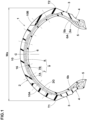
- FIG. 1 is a cross-sectional view of a motorcycle tire 1 of the present embodiment showing a tire meridian cross section including a tire rotational axis under a standard state of the tire 1.
- the tire 1 is for the front wheel of a motorcycle suitable for on-road sports driving.
- the size of the tire 1 is, for example, 120/70ZR17.
- the present invention is not limited to such tire.
- the "standard state” means a state of the tire when mounted on a standard wheel rim, and inflated to a standard tire pressure, but loaded with no tire load.
- the "standard state” means a standard usage state depending on the purpose of use of the tire and in a condition in which the tire is not attached to a vehicle and no tire load is applied,
- dimensions and positions of each part or portion of the tire refer to those under the standard state unless otherwise noted. Incidentally, even if the dimensions or positions cannot be measured directly under the standard state, for example, in the case of internal tire components, these can be measured using x-ray equipment etc.
- the “standard wheel rim” is a wheel rim specified for the tire in a standard system including standards on which the tire is based, for example, the "Standard rim” in JATMA, "Design Rim” in TRA, “Measuring Rim” in ETRTO.
- the “standard tire pressure” is the air pressure specified for the tire in a standard system including standards on which the tire is based, for example, the “maximum air pressure” in JATMA, "INFLATION PRESSURE” in ETRTO, and the maximum air pressure listed in the table "TIRE LOAD LIMITS AT VARIOUS COLD INFLATION PRESSURES" in TRA.
- the tire 1 in the present embodiment comprises a tread portion 2, a pair of sidewall portions 3, and a pair of bead portions 4.
- the sidewall portions 3 are respectively connected to both sides in the tire axial direction of the tread portion 2.
- the bead portions 4 are respectively connected to inner sides in the tire radial direction of the respective sidewall portions 3.
- a bead core 5 is embedded in each bead portion 4.
- the tire 1 comprises a carcass 6 extending between the paired bead portions 4.
- the carcass 6 comprises, for example, a carcass ply 6A comprising a plurality of carcass cords.
- the carcass cords (not shown) are arranged at an angle from 65 to 90 degrees with respect to the tire circumferential direction, for example.
- the carcass 6 in the present embodiment is composed of only one carcass ply 6A, but, it may be composed of a plurality of overlaid carcass plies.
- the carcass ply 6A comprises a main portion 6a and turnup portions 6b.
- the main portion 6a extends from the tread portion 2 through the sidewall portions 3 on both sides to the bead cores 5 of the bead portions 4 on both sides.
- the turnup portions 6b are continuous with the main portion 6a, and are each folded back around the bead core 5 from the inside to the outside in the tire axial direction.
- the tread portion 2 comprises a tread reinforcing layer 9 disposed outside the carcass 6 in the tire radial direction, and a tread rubber 2G disposed outside the tread reinforcing layer 9 in the tire radial direction.
- the tread reinforcing layer 9 includes a belt layer 7 and a band layer 8 disposed outside the belt layer 7 in the tire radial direction.
- the belt layer 7 is disposed adjacently to the outer side in the tire radial direction of the carcass 6.
- the belt layer 7 is arranged so as to reinforce a substantially entire width in the tire axial direction of the tread portion 2.
- the belt layer 7 is composed of, for example, two belt plies 7A and 7B.
- Each of the belt plies 7A and 7B is composed of rubberized belt cords arranged at an angle in a range from of 10 to 40 degrees with respect to the tire circumferential direction.
- the band layer 8 is arranged, for example, in a center part in the tire axial direction of the tread portion 2, and extends across the tire equator C.
- the band layer 8 comprises, for example, at least one band cord wound helically in the tire circumferential direction in order to suppress growth of the outer diameter of the tread portion 2 during high-speed running.
- the tread portion 2 has a first tread edge T1, a second tread edge T2 and a ground contacting surface 10 between the first tread edge T1 and the second tread edge T2.
- the ground contacting surface 10 refers to the entire radial outer surface of the tread portion 2 that may come into contact with the ground when running straight or turning.
- the ground contacting surface 10 is curved in an arc shape being convex outwardly in the tire radial direction so that a sufficient ground contacting area can be secured even when turning with a large camber angle or cornering with a large motorcycle lean angle.
- the first tread edge T1 and the second tread edge T2 correspond to the axially outermost ends of the ground contacting surface 10 which can come into contact with the road surface at the maximum camber angle.
- the tread width Wa is the distance in the tire axial direction from the first tread edge T1 to the second tread edge T2. In the present embodiment, since the ground contacting surface 10 is curved as described above, the tread width Wa corresponds to the maximum cross-section width of the tire.
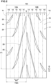
- FIG. 2 is a developed partial view of the ground contacting surface 10 of the tread portion 2. Specifically, FIG. 2 shows a part in the tire circumferential direction of the ground contacting surface 10 which is developed in a plane.
- the width in the tire axial direction of each part of the tread portion in this developed state is referred to as the developed width.
- the developed width from the first tread edge T1 to the second tread edge T2 is referred to as the developed tread width TW.
- the developed width from the tire equator C to the first tread edge T1 and that from the tire equator C to the second tread edge T2 are each referred to as the half developed tread width TWh.
- the tread portion 2 is provided with a unidirectional tread pattern for which an intended rotational direction R of the tire is specified to maximize tire performance.
- the intended rotational direction R may be indicated by letters or symbols, e.g. arrows which are formed, for example, in the sidewall portion 3 or the tread portion 2.
- the present invention is not limited to such a unidirectional tread pattern.
- the intended rotational direction R is indicated by an outline arrow.
- ground contacting surface 10 a part from the tire equator C to the first tread edge T1 is referred to as the first ground contacting surface 10A, and a part from the tire equator C to the second tread edge T2 is referred to as the second ground contacting surface 10B.
- first ground contacting surface 10A and the second ground contacting surface 10B have substantially same symmetrical configurations except that tread pattern components on one side of the tire equator are circumferentially shifted from those on the other side.
- the first ground contacting surface 10A is divided equally in the developed width direction of the first ground contacting surface 10A into five zones which are a first zone 11, a second zone 12, a third zone 13, a fourth zone 14 and a fifth zone 15 in order from the tire equator C to the first tread edge T1.
- the second ground contacting surface 10B is divided into a first zone 11, a second zone 12, a third zone 13, a fourth zone 14 and a fifth zone 15 in order from the tire equator C to the second tread edge T2. Accordingly, the developed width W1 of each of these zones is 20% of the half tread developed width TWh.
- the first zone 11 is located closest to the tire equator C; the second zone 12 is adjacent to the first zone 11 on the first tread edge T1 side; the third zone 13 is adjacent to the second zone 12 on the first tread edge T1 side; the fourth zone 14 is adjacent to the third zone 13 on the first tread edge T1 side; and the fifth zone 15 is adjacent to the fourth zone 14 on the first tread edge T1 side, and is located closest to the first tread edge T1.
- the second ground contacting surface 10B is also similar. That is, the above description can also be applied by replacing "first tread edge T1" with "second tread edge T2", so the description is omitted. In the drawings, the boundaries 16 of these zones are indicated by dash-dot lines.
- the land ratio of each zone is specified.
- the "land ratio" of a zone means a ratio Sb/Sa of the actual ground contact area Sb of the zone to the overall ground contact area Sa of the zone assuming there are no voids (grooves, recesses, sipes and the likes) at all.
- the land ratio La2 of the second zone 12 is set to be larger than the land ratio La1 of the first zone 11 and larger than the land ratio La3 of the third zone 13. This can be applied to both the first ground contacting surface 10A and the second ground contacting surface 10B. Thereby, the step wear of the tread portion 2 can be suppressed.
- the reason is as follows.
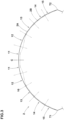
- FIG. 3 is a diagram conceptually showing changes in the profile of the tread portion 2.
- a solid line indicates a profile 2A of the tread portion 2 when not worn
- a two-dot chain line indicates a profile 2B of the tread portion 2 when tread wear has progressed to some extent.
- the degree of wear is somewhat exaggerated for easy understanding.
- the tread portion 2 of the motorcycle tire Since the profile of the tread portion 2 of the motorcycle tire is curved in an arc shape as shown in FIG. 3 , the tread portion 2 tends to wear easily in the vicinity of the tire equator C. On the other hand, when the motorcycle is running straight or when running at a camber angle of 0 degrees in substance, the edges in the tire axial direction of the ground contact patch are located near the second zones 12 of the tread portion 2. As a result, the so-called step wear tends to occur in the vicinities of the second zones 12.
- the land ratio La2 of the second zones 12 where step wear is likely to occur is made to be larger than the land ratios of the adjacent first zone 11 and third zone 13, the progressions of wear in these respective regions become uniform. Therefore, in the tire 1 according to the present invention, the step wear of the tread portion 2 can be effectively prevented.
- first ground contacting surface 10A can also be applied to the second ground contacting surface 10B. Therefore, if the descriptions are made for only the first ground contacting surface 10A, since such descriptions can be applied to the second ground contacting surface 10B, those of the second ground contacting surface 10B will be omitted.
- the land ratio La1 of the first zone 11 is, for example, 81% to 91%, preferably 84% to 88%.
- the land ratio La1 of the first zone 11 is smaller than the land ratio La2 of the second zone 12 by 8 to 12 percentage points.
- the first zone 11 has the smallest land ratio among the five zones 11 to 15. Thereby, wet performance during straight running can be improved while achieving the above-described effects.
- the land ratio La2 of the second zone 12 is, for example, 91% to 97%, preferably 93% to 95%. Further, in the present embodiment, it is preferable that the second zone has the largest land ratio among the five zones 11 to 15. Thereby, the step wear of the tread portion 2 can be surely suppressed.
- the land ratio La3 of the third zone 13 is, for example, 83% to 93%, preferably 86% to 90%.
- the land ratio La3 of the third zone 13 is smaller than the land ratio La2 of the second zone 12 by 4 to 8 percentage points.
- the land ratio La3 of the third zone 13 is preferably larger than the land ratio La1 of the first zone 11.
- the land ratio La3 is larger than the land ratio La1 by 2 to 6 percentage points.
- the land ratio La4 of the fourth zone 14 is, for example, 89% to 93%.
- the land ratio La4 of the fourth zone 14 is larger than the land ratio La3 of the third zone 13.
- the land ratio La4 is larger than the land ratio La3 by 1 to 3 percentage points.
- the land ratio La5 of the fifth zone 15 is, for example, 91% to 95%.
- the land ratio La5 of the fifth zone 15 is larger than the land ratio La4 of the fourth zone 14.
- the land ratio La5 is larger than the land ratio La4 by 2 to 6 percentage points.
- the land ratios La1 to La5 of the first to fifth zones satisfy the following condition (1) in order to further improve the transient characteristics during turning: La2 > La5 > La4 > La3 > La1
- the first ground contacting surface 10A is provided with a plurality of main oblique grooves 20 and a plurality of auxiliary oblique grooves 25 which are arranged in the tire circumferential direction as shown in FIG. 2 .
- tires according to the present invention are not to be limited to the tread pattern shown in FIG. 2 .
- the main oblique grooves 20 are arranged circumferentially of the tire at a circumferential pitch length P1 (namely, the circumferential distance between every two of the adjacent main oblique grooves 20) which is, for example, in a range from 70% to 90% of the developed tread width TW.
- the auxiliary oblique grooves 25 are also arranged in the same manner, namely, at the circumferential pitch length P1.
- a region which is formed by virtually moving in parallel one main oblique groove 20 toward the first tread edge T1 overlaps with another main oblique groove 20 adjacent to the above-said one main oblique groove 20 on one side in the tire circumferential direction (e.g. the upper side in FIG. 2 ).
- the main oblique grooves 20 disposed in each of the first and second ground contacting surfaces 10A and 10B are arranged over the entire circumference of the tire while satisfying the above-described positional relationship.
- the circumferential extents of every two of the circumferentially adjacent main oblique grooves 20 are overlapped with each other in the tire circumferential direction.
- a region which is formed by virtually moving in parallel one main oblique groove 20 toward the first tread edge T1 overlaps with two of the auxiliary oblique grooves 25.
- the circumferential extent of each of the main oblique grooves 20 overlaps in the tire circumferential direction with the circumferential extents of two of the circumferentially adjacent auxiliary oblique grooves 25 which are located axially outside the above-said each of the main oblique grooves 20.
- FIG. 4 is an enlarged view showing one of the main oblique grooves 20 and one of the auxiliary oblique grooves 25.
- each main oblique groove 20 is inclined toward the opposite direction to the intended rotational direction R while extending from the axially inside toward the axially outside of the tire.
- the average inclination angle ⁇ 1 of the main oblique groove 20 with respect to the tire circumferential direction is, for example, set in a range from 5 to 10 degrees.
- Such main oblique grooves 20 can exhibit excellent drainage performance by utilizing the rotation of the tire when running in wet conditions.
- the average inclination angle ⁇ 1 corresponds to a value obtained by dividing the groove center line of the main oblique groove 20 into a plurality of minute sections
- the main oblique groove 20 in this example extends from the first zone 11 to the fourth zone 14 through the second zone 12 and the third zone 13. And the main oblique groove 20 does not exist in the fifth zone 15.
- the main oblique groove 20 does not extend across the tire equator C.
- the main oblique groove 20 has a length L1 in the tire circumferential direction which is in a range from 130% to 200% of the above-said one pitch length P1 of the main oblique grooves 20.
- the main oblique groove 20 in this example comprises a narrow groove section 21, an inner groove section 22 and an outer groove section 23 in the longitudinal direction of the main oblique groove 20.
- the narrow groove section 21 is positioned in a center portion of the main oblique groove 20 in the longitudinal direction, and extends over the entire length with a relatively small constant groove width W2.
- the inner groove section 22 is connected to the narrow groove section 21 on the tire equator side, and has a groove width larger than that of the narrow groove section 21.
- the outer groove section 23 is connected to the narrow groove section 21 on the first tread edge T1 side, and has a groove width larger than that of the narrow groove section 21.
- the constant groove width W2 of the narrow groove section 21 is 3.0 mm or less, preferably 0.5 to 2.5 mm, more preferably 1.0 to 2.0 mm. Further, an almost entire part of the narrow groove section 21 is located in the second zone 12. More specifically, 80% or more of the opening area of the narrow groove section 21 is located in the second zone 12. Thereby, the land ratio La2 of the second zone 12 is increased, and it becomes possible to achieve the above-described land ratio relationship.
- the inner groove section 22 is arranged so that an almost entire part thereof is located in the first zone 11. Specifically, 80% or more, preferably 90% or more, in this example 100% of the opening area of the inner groove section 22 is located in the first zone 11.
- the inner groove section 22 has a groove width larger than the narrow groove section 21 as described above. To say this accurately, the average groove width of the inner groove section 22 is larger than the constant groove width W2 of the narrow groove section 21.
- the average groove width corresponds to a value obtained by dividing the opening area of the inner groove section 22 by the length of the groove center line of the inner groove section 22.
- the outer groove section 23 is arranged from the third zone 13 into the fourth zone 14, and does not exist in either the second zone 12 or the fifth zone 15.
- the average groove width of the outer groove section 23 is larger than the constant groove width W2 of the narrow groove section 21.
- the opening area of the outer groove section 23 exists in the third zone 13, and accordingly, the remaining part of the opening area exists in the fourth zone 14.
- the auxiliary oblique grooves 25 are disposed on the first tread edge T1 side of the main oblique grooves 20.
- the auxiliary oblique grooves 25 are inclined in the same direction as the main oblique grooves 20 with respect to the tire circumferential direction in each of the first and second ground contacting surfaces 10A and 10B as shown in FIG. 2 .
- the average inclination angle ⁇ 2 of the auxiliary oblique grooves 25 with respect to the tire circumferential direction is, for example, set in a range from 30 to 50 degrees.
- the average inclination angle ⁇ 2 of the auxiliary oblique grooves 25 is larger than the average inclination angle ⁇ 1 of the main oblique grooves 20. This improves stability when turning at a relatively large camber angle where the fourth zone 14 or the fifth zone 15 contacts with the ground.
- the auxiliary oblique groove 25 is arranged from the fourth zone 14 into the fifth zone 15.
- the auxiliary oblique groove 25 does not exist in the third zone 13. Further, the auxiliary oblique groove 25 is not open at the first tread edge T1. Namely, the auxiliary oblique groove 25 ends without reaching the first tread edge T1.
- a region which is formed by virtually moving in parallel the auxiliary oblique groove 25 toward the tire equator in the tire axial direction overlaps with both the narrow groove section 21 and the outer groove section 23 of the axially adjacent main oblique groove 20.
- the distance in the tire axial direction between the end 25a on the tire equator C side, of the auxiliary oblique groove 25 and the end 20a on the first tread edge T1 side, of the main oblique groove 20 is preferably 10% or less, more preferably 5% or less of the developed width W1 (shown in FIG. 2 ) of one of the five zones.
- the length L2 in the tire circumferential direction of the auxiliary oblique groove 25 is 10% to 25% of the length L1 in the tire circumferential direction of the main oblique groove 20. As a result, the transient characteristics during turning may be further improved.
- FIG. 5 is a cross-sectional view of the tread portion 2 of FIG. 1 .
- the tread portion 2 comprises a tread rubber 2G which includes a crown tread rubber 31, and a shoulder tread rubber 32 disposed on each side in the tire axial direction of the crown tread rubber 31 as shown in FIG. 5 .
- the crown tread rubber 31 and the shoulder tread rubbers 32 are made of different rubber compounds.
- the crown tread rubber 31 is disposed so as to extend across the tire equator C.
- the two shoulder tread rubbers 32 extend axially outwardly from the crown tread rubber 31 to the first and second tread edges T1 and T2, respectively. Thereby, the ground contacting surface 10 of the tread portion 2 is formed by the radially outer surfaces of the crown tread rubber 31 and the two shoulder tread rubbers 32.
- the boundary surface 33a between the crown tread rubber 31 and the shoulder tread rubber 32 is located axially outside the second zone 12, and preferably located in the third zone 13 or the fourth zone 14. Thereby, it becomes possible to more effectively suppress the step wear of the tread portion 2.
- the loss tangent tan ⁇ refers to a value measured under the following conditions in accordance with Japanese Industrial Standard (JIS) K6394, using a viscoelastic spectrometer manufactured by Iwamoto Seisakusho KK.
- the boundary surface 33a in each boundary 33 between the crown tread rubber 31 and the shoulder tread rubber 32 extends linearly, and the boundary surface 33a is inclined at an angle ⁇ 3 in a range from 30 to 50 degrees, for example, with respect to the normal direction to the radially outer surface of the tread rubber 2G as shown in FIG. 5 .
- the boundary surface 33a is inclined to the axially inside while extending from the radially inner edge to the radially outer edge of the boundary surface 33a.
- the shoulder tread rubber 32 is disposed on the radially outside of the belt layer 7 such that the boundary 33 is located on the radially outside of the belt layer 7, and edges in the tire axial direction of the belt plies 7A and 7B are located axially outside the boundary line between the fourth zone 14 and the fifth zone 15 as shown in FIG. 5 .
Landscapes
- Engineering & Computer Science (AREA)
- Mechanical Engineering (AREA)
- Tires In General (AREA)
Abstract
Description
- The present invention relates to a motorcycle tire.
-
Patent Document 1 listed below discloses a pneumatic tire for motorcycles, in which a land ratio of each zone of the tread portion is specified.
In this tire, a range in the tire axial direction of the tread portion from the tire equator to each tread edge is divided equally into five zones, and the land ratios of the first to fifth zones are specifically defined.
By having the above-described feature, the tire is expected to be provided with improved response behavior on wet road surfaces, and improved transient characteristics such as grip performance when initiating turning, and the like. - Patent Document 1:
Japanese Patent Application Publication No. 2016-141226 - In the tire disclosed in
Patent Document 1, when running straight (when running at a camber angle of 0 degrees), edges in the tire axial direction of the ground contacting area or patch tend to locate in the vicinities of the second zones.
As a result, so-called step wear is liable to occur near the edges of the above-mentioned ground contacting area, therefore, there is a need for improvement. - The present invention was made in view of the above-mentioned circumstances, and a primary objective of the present invention is to provide a motorcycle tire in which the above-mentioned step wear in the tread portion can be suppressed.
- According to the present invention, a motorcycle tire comprises:
- a tread portion having a first tread edge, a second tread edge and a ground contacting surface between the first tread edge and the second tread edge, the ground contacting surface including a first ground contacting surface between the tire equator and the first tread edge,
wherein - when the developed width of the first ground contacting surface is equally divided into five zones which are a first zone, a second zone, a third zone, a fourth zone and a fifth zone located in order from the tire equator to the first tread edge,
a land ratio La2 of the second zone is larger than a land ratio La1 of the first zone, and larger than a land ratio La3 of the third zone. - In the motorcycle tire according to the present invention, since the above-described configuration is employed, the step wear of the tread portion can be suppressed.
-
-
FIG. 1 is a cross-sectional view of a motorcycle tire as an embodiment of the present invention. -
FIG. 2 is a developed view of a part of the ground contacting surface of the tread portion shown inFIG. 1 . -
FIG. 3 is a diagram showing the profile of the tread portion. -
FIG. 4 is an enlarged view showing a main oblique groove and a auxiliary oblique groove shown inFIG. 2 . -
FIG. 5 is a cross-sectional view of the tread portion shown inFIG. 1 . - Hereinafter, an embodiment of the present invention will be described in detail in conjunction with accompanying drawings.
- Although the drawings illustrate features of the embodiment, the illustrated features may contain exaggeration different from the actual dimensional relationship for easy understanding.
-
FIG. 1 is a cross-sectional view of amotorcycle tire 1 of the present embodiment showing a tire meridian cross section including a tire rotational axis under a standard state of thetire 1.
In the present embodiment, thetire 1 is for the front wheel of a motorcycle suitable for on-road sports driving. The size of thetire 1 is, for example, 120/70ZR17.
However, the present invention is not limited to such tire. - In the case that the
tire 1 is a type of pneumatic tire for which various standards have been established, the "standard state" means a state of the tire when mounted on a standard wheel rim, and inflated to a standard tire pressure, but loaded with no tire load. - In the case that the
tire 1 is a tire for which various standards are not yet established, the "standard state" means a standard usage state depending on the purpose of use of the tire and in a condition in which the tire is not attached to a vehicle and no tire load is applied, - In this application including specification and claims, dimensions and positions of each part or portion of the tire refer to those under the standard state unless otherwise noted.
Incidentally, even if the dimensions or positions cannot be measured directly under the standard state, for example, in the case of internal tire components, these can be measured using x-ray equipment etc. - The "standard wheel rim" is a wheel rim specified for the tire in a standard system including standards on which the tire is based, for example, the "Standard rim" in JATMA, "Design Rim" in TRA, "Measuring Rim" in ETRTO.
- The "standard tire pressure" is the air pressure specified for the tire in a standard system including standards on which the tire is based, for example, the "maximum air pressure" in JATMA, "INFLATION PRESSURE" in ETRTO, and the maximum air pressure listed in the table "TIRE LOAD LIMITS AT VARIOUS COLD INFLATION PRESSURES" in TRA.
- As shown in
FIG. 1 , thetire 1 in the present embodiment comprises atread portion 2, a pair ofsidewall portions 3, and a pair ofbead portions 4.
Thesidewall portions 3 are respectively connected to both sides in the tire axial direction of thetread portion 2.
Thebead portions 4 are respectively connected to inner sides in the tire radial direction of therespective sidewall portions 3. In eachbead portion 4, abead core 5 is embedded. - The
tire 1 comprises acarcass 6 extending between the pairedbead portions 4. Thecarcass 6 comprises, for example, acarcass ply 6A comprising a plurality of carcass cords.
The carcass cords (not shown) are arranged at an angle from 65 to 90 degrees with respect to the tire circumferential direction, for example.
Thecarcass 6 in the present embodiment is composed of only onecarcass ply 6A, but, it may be composed of a plurality of overlaid carcass plies.
Thecarcass ply 6A comprises amain portion 6a and turnupportions 6b.
Themain portion 6a extends from thetread portion 2 through thesidewall portions 3 on both sides to thebead cores 5 of thebead portions 4 on both sides.
Theturnup portions 6b are continuous with themain portion 6a, and are each folded back around thebead core 5 from the inside to the outside in the tire axial direction. - The
tread portion 2 comprises atread reinforcing layer 9 disposed outside thecarcass 6 in the tire radial direction, and atread rubber 2G disposed outside thetread reinforcing layer 9 in the tire radial direction. - The
tread reinforcing layer 9 includes abelt layer 7 and aband layer 8 disposed outside thebelt layer 7 in the tire radial direction. - The
belt layer 7 is disposed adjacently to the outer side in the tire radial direction of thecarcass 6. Thebelt layer 7 is arranged so as to reinforce a substantially entire width in the tire axial direction of thetread portion 2.
Thebelt layer 7 is composed of, for example, twobelt plies belt plies - The
band layer 8 is arranged, for example, in a center part in the tire axial direction of thetread portion 2, and extends across the tire equator C.
Theband layer 8 comprises, for example, at least one band cord wound helically in the tire circumferential direction in order to suppress growth of the outer diameter of thetread portion 2 during high-speed running. - The
tread portion 2 has a first tread edge T1, a second tread edge T2 and aground contacting surface 10 between the first tread edge T1 and the second tread edge T2. - Here, the
ground contacting surface 10 refers to the entire radial outer surface of thetread portion 2 that may come into contact with the ground when running straight or turning. - In the tire meridian cross section, the
ground contacting surface 10 is curved in an arc shape being convex outwardly in the tire radial direction so that a sufficient ground contacting area can be secured even when turning with a large camber angle or cornering with a large motorcycle lean angle. - The first tread edge T1 and the second tread edge T2 correspond to the axially outermost ends of the
ground contacting surface 10 which can come into contact with the road surface at the maximum camber angle. - The tread width Wa is the distance in the tire axial direction from the first tread edge T1 to the second tread edge T2.
In the present embodiment, since theground contacting surface 10 is curved as described above, the tread width Wa corresponds to the maximum cross-section width of the tire. -
FIG. 2 is a developed partial view of theground contacting surface 10 of thetread portion 2. Specifically,FIG. 2 shows a part in the tire circumferential direction of theground contacting surface 10 which is developed in a plane. - In this specification, the width in the tire axial direction of each part of the tread portion in this developed state is referred to as the developed width.
Further, in this specification, the developed width from the first tread edge T1 to the second tread edge T2 is referred to as the developed tread width TW.
Furthermore, the developed width from the tire equator C to the first tread edge T1 and that from the tire equator C to the second tread edge T2 are each referred to as the half developed tread width TWh. - In this embodiment, as shown in
FIG. 2 , thetread portion 2 is provided with a unidirectional tread pattern for which an intended rotational direction R of the tire is specified to maximize tire performance.
The intended rotational direction R may be indicated by letters or symbols, e.g. arrows which are formed, for example, in thesidewall portion 3 or thetread portion 2. However, the present invention is not limited to such a unidirectional tread pattern. In the drawings, the intended rotational direction R is indicated by an outline arrow. - In the
ground contacting surface 10, a part from the tire equator C to the first tread edge T1 is referred to as the firstground contacting surface 10A, and a part from the tire equator C to the second tread edge T2 is referred to as the secondground contacting surface 10B. - In this embodiment, the first
ground contacting surface 10A and the secondground contacting surface 10B have substantially same symmetrical configurations except that tread pattern components on one side of the tire equator are circumferentially shifted from those on the other side. - In the present invention, the first
ground contacting surface 10A is divided equally in the developed width direction of the firstground contacting surface 10A into five zones which are afirst zone 11, asecond zone 12, athird zone 13, afourth zone 14 and afifth zone 15 in order from the tire equator C to the first tread edge T1.
In the same way, the secondground contacting surface 10B is divided into afirst zone 11, asecond zone 12, athird zone 13, afourth zone 14 and afifth zone 15 in order from the tire equator C to the second tread edge T2.
Accordingly, the developed width W1 of each of these zones is 20% of the half tread developed width TWh. - In the first
ground contacting surface 10A, thefirst zone 11 is located closest to the tire equator C; thesecond zone 12 is adjacent to thefirst zone 11 on the first tread edge T1 side; thethird zone 13 is adjacent to thesecond zone 12 on the first tread edge T1 side; thefourth zone 14 is adjacent to thethird zone 13 on the first tread edge T1 side; and thefifth zone 15 is adjacent to thefourth zone 14 on the first tread edge T1 side, and is located closest to the first tread edge T1.
The secondground contacting surface 10B is also similar. That is, the above description can also be applied by replacing "first tread edge T1" with "second tread edge T2", so the description is omitted.
In the drawings, theboundaries 16 of these zones are indicated by dash-dot lines. - In the
tire 1 according to the present invention, the land ratio of each zone is specified. - Here, the "land ratio" of a zone means a ratio Sb/Sa of the actual ground contact area Sb of the zone to the overall ground contact area Sa of the zone assuming there are no voids (grooves, recesses, sipes and the likes) at all.
- In the present invention, the land ratio La2 of the
second zone 12 is set to be larger than the land ratio La1 of thefirst zone 11 and larger than the land ratio La3 of thethird zone 13.
This can be applied to both the firstground contacting surface 10A and the secondground contacting surface 10B.
Thereby, the step wear of thetread portion 2 can be suppressed. The reason is as follows. -
FIG. 3 is a diagram conceptually showing changes in the profile of thetread portion 2.
InFIG. 3 , a solid line indicates aprofile 2A of thetread portion 2 when not worn, and a two-dot chain line indicates aprofile 2B of thetread portion 2 when tread wear has progressed to some extent. In this figure, however, the degree of wear is somewhat exaggerated for easy understanding. - Since the profile of the
tread portion 2 of the motorcycle tire is curved in an arc shape as shown inFIG. 3 , thetread portion 2 tends to wear easily in the vicinity of the tire equator C.
On the other hand, when the motorcycle is running straight or when running at a camber angle of 0 degrees in substance, the edges in the tire axial direction of the ground contact patch are located near thesecond zones 12 of thetread portion 2.
As a result, the so-called step wear tends to occur in the vicinities of thesecond zones 12. - In the present invention, since the land ratio La2 of the
second zones 12 where step wear is likely to occur is made to be larger than the land ratios of the adjacentfirst zone 11 andthird zone 13, the progressions of wear in these respective regions become uniform. Therefore, in thetire 1 according to the present invention, the step wear of thetread portion 2 can be effectively prevented. - The features described below for the first
ground contacting surface 10A can also be applied to the secondground contacting surface 10B. Therefore, if the descriptions are made for only the firstground contacting surface 10A, since such descriptions can be applied to the secondground contacting surface 10B, those of the secondground contacting surface 10B will be omitted. - Hereinafter, more detail of features of the
motorcycle tire 1 according to the present embodiment will be explained.
The features described below are optional in the present invention, but preferable in the present embodiment. - The land ratio La1 of the
first zone 11 is, for example, 81% to 91%, preferably 84% to 88%.
Preferably, the land ratio La1 of thefirst zone 11 is smaller than the land ratio La2 of thesecond zone 12 by 8 to 12 percentage points.
Further, thefirst zone 11 has the smallest land ratio among the fivezones 11 to 15. Thereby, wet performance during straight running can be improved while achieving the above-described effects. - The land ratio La2 of the
second zone 12 is, for example, 91% to 97%, preferably 93% to 95%.
Further, in the present embodiment, it is preferable that the second zone has the largest land ratio among the fivezones 11 to 15.
Thereby, the step wear of thetread portion 2 can be surely suppressed. - The land ratio La3 of the
third zone 13 is, for example, 83% to 93%, preferably 86% to 90%.
Preferably, the land ratio La3 of thethird zone 13 is smaller than the land ratio La2 of thesecond zone 12 by 4 to 8 percentage points.
Further, the land ratio La3 of thethird zone 13 is preferably larger than the land ratio La1 of thefirst zone 11. Specifically, it is preferable that the land ratio La3 is larger than the land ratio La1 by 2 to 6 percentage points.
Thereby, when turning at a relatively small camber angle where up to thethird zone 13 comes into contact with the ground, the transient characteristic with respect to the response when leaning the motorcycle become linear. Hereinafter, such effect will be sometimes expressed simply as "the transient characteristic when turning is improved". - The land ratio La4 of the
fourth zone 14 is, for example, 89% to 93%.
Preferably, the land ratio La4 of thefourth zone 14 is larger than the land ratio La3 of thethird zone 13. Specifically, it is preferable that the land ratio La4 is larger than the land ratio La3 by 1 to 3 percentage points.
Thereby, the transient characteristic when turning may be further improved. - The land ratio La5 of the
fifth zone 15 is, for example, 91% to 95%.
Preferably, the land ratio La5 of thefifth zone 15 is larger than the land ratio La4 of thefourth zone 14. Specifically, it is preferable that the land ratio La5 is larger than the land ratio La4 by 2 to 6 percentage points.
Thereby, during cornering at the maximum camber angle, excellent cornering performance can be exerted. - Further, it is preferable for the
tire 1 in the present embodiment that
the land ratios La1 to La5 of the first to fifth zones satisfy the following condition (1) in order to further improve the transient characteristics during turning:
- In the
tread portion 2 of the present embodiment, in order to achieve the above-mentioned land ratio relationship, the firstground contacting surface 10A is provided with a plurality of mainoblique grooves 20 and a plurality ofauxiliary oblique grooves 25 which are arranged in the tire circumferential direction as shown inFIG. 2 .
However, tires according to the present invention are not to be limited to the tread pattern shown inFIG. 2 . - In the first
ground contacting surface 10A, themain oblique grooves 20 are arranged circumferentially of the tire at a circumferential pitch length P1 (namely, the circumferential distance between every two of the adjacent main oblique grooves 20) which is, for example, in a range from 70% to 90% of the developed tread width TW. Further, theauxiliary oblique grooves 25 are also arranged in the same manner, namely, at the circumferential pitch length P1. - It is preferable that, in the developed view of the
tread portion 2 as shown inFIG. 2 , a region which is formed by virtually moving in parallel onemain oblique groove 20 toward the first tread edge T1, overlaps with anothermain oblique groove 20 adjacent to the above-said onemain oblique groove 20 on one side in the tire circumferential direction (e.g. the upper side inFIG. 2 ). - In the present embodiment, the
main oblique grooves 20 disposed in each of the first and secondground contacting surfaces
In other words, the circumferential extents of every two of the circumferentially adjacentmain oblique grooves 20 are overlapped with each other in the tire circumferential direction.
Thereby, uneven wear of thetread portion 2 can be suppressed, and the transient characteristics during turning can also be improved. - Further, it is preferable that a region which is formed by virtually moving in parallel one
main oblique groove 20 toward the first tread edge T1 overlaps with two of theauxiliary oblique grooves 25.
In other words, the circumferential extent of each of themain oblique grooves 20 overlaps in the tire circumferential direction with the circumferential extents of two of the circumferentially adjacentauxiliary oblique grooves 25 which are located axially outside the above-said each of themain oblique grooves 20.
Thereby wet performance can be improved. -
FIG. 4 is an enlarged view showing one of themain oblique grooves 20 and one of theauxiliary oblique grooves 25.
As shown inFIG. 4 , eachmain oblique groove 20 is inclined toward the opposite direction to the intended rotational direction R while extending from the axially inside toward the axially outside of the tire.
The average inclination angle θ1 of themain oblique groove 20 with respect to the tire circumferential direction is, for example, set in a range from 5 to 10 degrees.
Such mainoblique grooves 20 can exhibit excellent drainage performance by utilizing the rotation of the tire when running in wet conditions. - Here, the average inclination angle θ1 corresponds to a value obtained by dividing the groove center line of the
main oblique groove 20 into a plurality of minute sections, - summing up angles of the minute sections with respect to the tire circumferential direction, and
- dividing the sum of the angles by the number of the minute sections.
- The
main oblique groove 20 in this example extends from thefirst zone 11 to thefourth zone 14 through thesecond zone 12 and thethird zone 13. And themain oblique groove 20 does not exist in thefifth zone 15.
Preferably, themain oblique groove 20 does not extend across the tire equator C. Preferably, themain oblique groove 20 has a length L1 in the tire circumferential direction which is in a range from 130% to 200% of the above-said one pitch length P1 of themain oblique grooves 20. - The
main oblique groove 20 in this example comprises anarrow groove section 21, aninner groove section 22 and anouter groove section 23 in the longitudinal direction of themain oblique groove 20.
Thenarrow groove section 21 is positioned in a center portion of themain oblique groove 20 in the longitudinal direction, and extends over the entire length with a relatively small constant groove width W2.
Theinner groove section 22 is connected to thenarrow groove section 21 on the tire equator side, and has a groove width larger than that of thenarrow groove section 21.
Theouter groove section 23 is connected to thenarrow groove section 21 on the first tread edge T1 side, and has a groove width larger than that of thenarrow groove section 21. - The constant groove width W2 of the
narrow groove section 21 is 3.0 mm or less, preferably 0.5 to 2.5 mm, more preferably 1.0 to 2.0 mm.
Further, an almost entire part of thenarrow groove section 21 is located in thesecond zone 12. More specifically, 80% or more of the opening area of thenarrow groove section 21 is located in thesecond zone 12. Thereby, the land ratio La2 of thesecond zone 12 is increased, and it becomes possible to achieve the above-described land ratio relationship. - The
inner groove section 22 is arranged so that an almost entire part thereof is located in thefirst zone 11. Specifically, 80% or more, preferably 90% or more, in this example 100% of the opening area of theinner groove section 22 is located in thefirst zone 11. - The
inner groove section 22 has a groove width larger than thenarrow groove section 21 as described above. To say this accurately, the average groove width of theinner groove section 22 is larger than the constant groove width W2 of thenarrow groove section 21. - Thereby, wet performance during straight running can be ensured.
- Here, the average groove width corresponds to a value obtained by dividing the opening area of the
inner groove section 22 by the length of the groove center line of theinner groove section 22. - The same applies to average groove widths appearing in the following description of this specification.
- The
outer groove section 23 is arranged from thethird zone 13 into thefourth zone 14, and does not exist in either thesecond zone 12 or thefifth zone 15. - The average groove width of the
outer groove section 23 is larger than the constant groove width W2 of thenarrow groove section 21. - Further, 50% or more, preferably 60% or more of the opening area of the
outer groove section 23 exists in thethird zone 13, and accordingly, the remaining part of the opening area exists in thefourth zone 14. Thereby, the transient characteristics during turning can be improved. - In the
main oblique groove 20 in this example, - the axially outer groove edge thereof extends substantially straight or is smoothly slightly curved between the axially
outer end 20a and the axially inner end of themain oblique groove 20, and - the axially inner groove edge thereof is bulged out on both sides of the
narrow groove section 21, namely, in theinner groove section 22 and theouter groove section 23. - The
auxiliary oblique grooves 25 are disposed on the first tread edge T1 side of themain oblique grooves 20. - The
auxiliary oblique grooves 25 are inclined in the same direction as themain oblique grooves 20 with respect to the tire circumferential direction in each of the first and secondground contacting surfaces FIG. 2 . - The average inclination angle θ2 of the
auxiliary oblique grooves 25 with respect to the tire circumferential direction is, for example, set in a range from 30 to 50 degrees. Preferably, the average inclination angle θ2 of theauxiliary oblique grooves 25 is larger than the average inclination angle θ1 of themain oblique grooves 20.
This improves stability when turning at a relatively large camber angle where thefourth zone 14 or thefifth zone 15 contacts with the ground. - In the auxiliary
secondary oblique groove 25, - the axially outer groove edge thereof extends substantially straight or is smoothly slightly curved between the axially outer end and the axially inner end of the auxiliary
secondary oblique groove 25, and - the axially inner groove edge thereof is bulged out.
- The
auxiliary oblique groove 25 is arranged from thefourth zone 14 into thefifth zone 15.
Theauxiliary oblique groove 25 does not exist in thethird zone 13.
Further, theauxiliary oblique groove 25 is not open at the first tread edge T1. Namely, theauxiliary oblique groove 25 ends without reaching the first tread edge T1. - Preferably, a region which is formed by virtually moving in parallel the
auxiliary oblique groove 25 toward the tire equator in the tire axial direction, overlaps with both thenarrow groove section 21 and theouter groove section 23 of the axially adjacentmain oblique groove 20. - The distance in the tire axial direction between the
end 25a on the tire equator C side, of theauxiliary oblique groove 25 and theend 20a on the first tread edge T1 side, of themain oblique groove 20 is preferably 10% or less, more preferably 5% or less of the developed width W1 (shown inFIG. 2 ) of one of the five zones. - The length L2 in the tire circumferential direction of the
auxiliary oblique groove 25 is 10% to 25% of the length L1 in the tire circumferential direction of themain oblique groove 20.
As a result, the transient characteristics during turning may be further improved. -
FIG. 5 is a cross-sectional view of thetread portion 2 ofFIG. 1 .
Thetread portion 2 comprises atread rubber 2G which includes acrown tread rubber 31, and ashoulder tread rubber 32 disposed on each side in the tire axial direction of thecrown tread rubber 31 as shown inFIG. 5 .
Thecrown tread rubber 31 and the shoulder tread rubbers 32 are made of different rubber compounds.
Thecrown tread rubber 31 is disposed so as to extend across the tire equator C.
The two shoulder tread rubbers 32 extend axially outwardly from thecrown tread rubber 31 to the first and second tread edges T1 and T2, respectively.
Thereby, theground contacting surface 10 of thetread portion 2 is formed by the radially outer surfaces of thecrown tread rubber 31 and the two shoulder tread rubbers 32. - In each of the first and second
ground contacting surfaces boundary surface 33a between thecrown tread rubber 31 and theshoulder tread rubber 32 is located axially outside thesecond zone 12, and preferably located in thethird zone 13 or thefourth zone 14.
Thereby, it becomes possible to more effectively suppress the step wear of thetread portion 2. - The
crown tread rubber 31 and theshoulder tread rubber 32 have different loss tangent values.
It is preferable that the loss tangent tanδ at 0 degrees C of thecrown tread rubber 31 is larger than the loss tangent tanδ at 0 degrees C of theshoulder tread rubber 32. This makes it easier to warm thecrown tread rubber 31 up to appropriate temperatures at the beginning of running.
It is also preferable that the loss tangent tanδ at 70 degrees C of theshoulder tread rubber 32 is larger than the loss tangent tanδ at 70 degrees C of thecrown tread rubber 31. This makes it easier to warm theshoulder tread rubber 32 up to appropriate temperatures to exert high road grip performance during cornering. - In this application, the loss tangent tanδ refers to a value measured under the following conditions in accordance with Japanese Industrial Standard (JIS) K6394, using a viscoelastic spectrometer manufactured by Iwamoto Seisakusho KK.
- Initial strain: 10%
- Amplitude: +/-1%
- Frequency: 10 Hz
- Deformation mode: tensile
- In the cross-sectional view of the
tread portion 2, as shown inFIG. 5 , theboundary surface 33a in eachboundary 33 between thecrown tread rubber 31 and theshoulder tread rubber 32 extends linearly, and theboundary surface 33a is inclined at an angle θ3 in a range from 30 to 50 degrees, for example, with respect to the normal direction to the radially outer surface of thetread rubber 2G as shown inFIG. 5 .
Further, in the present embodiment, theboundary surface 33a is inclined to the axially inside while extending from the radially inner edge to the radially outer edge of theboundary surface 33a. - The
crown tread rubber 31 is disposed on the radially outside of theband layer 8 such that theedges 8a in the tire axial direction of theband layer 8 are positioned axially inside theboundary surfaces 33a, respectively.
In the present embodiment, the boundary surfaces 33a are respectively located in thethird zones 13, and
astraight line 8b drawn normally to the radially outer surface of thetread rubber 2G passing through eachedge 8a of theband layer 8 is located in thesecond zone 12.
Owing to such arrangement of theband layer 8, it becomes possible to further suppress the step wear of thetread portion 2.
Further, in the present embodiment, theshoulder tread rubber 32 is disposed on the radially outside of thebelt layer 7 such that theboundary 33 is located on the radially outside of thebelt layer 7, and edges in the tire axial direction of the belt plies 7A and 7B are located axially outside the boundary line between thefourth zone 14 and thefifth zone 15 as shown inFIG. 5 . - While detailed description has been made of a motorcycle tire as an embodiment of the present invention, the present invention can be embodied in various forms without being limited to the illustrated specific embodiment.
-
- 2
- tread portion
- 10
- ground contacting surface
- 10A
- first ground contacting surface
- 11
- first zone
- 12
- second zone
- 13
- third zone
- 14
- fourth zone
- 15
- fifth zone
- T1
- first tread edge
- T2
- second tread edge
Claims (15)
- A motorcycle tire comprising a tread portion having a first tread edge, a second tread edge and a ground contacting surface therebetween,the ground contacting surface comprising a first ground contacting surface from a tire equator to the first tread edge,when the first ground contacting surface is divided equally in a developed width direction of the first ground contacting surface into five zones which are a first zone, a second zone, a third zone, a fourth zone and a fifth zone in order from the tire equator to the first tread edge,a land ratio La2 of the second zone is larger than a land ratio La1 of the first zone and larger than a land ratio La3 of the third zone.
- The motorcycle tire according to claim 1, wherein
the land ratio La3 of the third zone is larger than the land ratio La1 of the first zone. - The motorcycle tire according to claim 2, whereina land ratio La4 of the fourth zone is larger than the land ratio La3 of the third zone, anda land ratio La5 of the fifth zone is larger than the land ratio La4 of the fourth zone.
- The motorcycle tire according to claim 3, wherein
the land ratio La2 of the second zone is largest among the five zones. - The motorcycle tire according to any one of claims 1 to 4, whereinthe land ratio La1 of the first zone is 81% to 91%,the land ratio La2 of the second zone is 91% to 97%, andthe land ratio La3 of the third zone is 83% to 93%.
- The motorcycle tire according to any one of claims 1 to 5, whereinthe first ground contacting surface is formed by a crown tread rubber and a shoulder tread rubber which are made of different rubber compounds, andin the first ground contacting surface, a boundary between the crown tread rubber and the shoulder tread rubber is positioned on the first tread edge side of the second zone.
- The motorcycle tire according to claim 6, wherein
the boundary is located in the third zone or alternatively in the fourth zone. - The motorcycle tire according to claim 6 or 7, wherein
a loss tangent tanδ at 0 degrees C of the crown tread rubber is larger than a loss tangent tanδ at 0 degrees C of the shoulder tread rubber. - The motorcycle tire according to any one of claims 6 to 8, wherein
a loss tangent tanδ at 70 degrees C of the shoulder tread rubber is larger than a loss tangent tanδ at 70 degrees C of the crown tread rubber. - The motorcycle tire according to any one of claims 1 to 9, whereinthe ground contacting surface comprises a second ground contacting surface from the tire equator to the second tread edge,when the second ground contacting surface is divided equally in the developed width direction of the second ground contacting surface into five zones which are a first zone, a second zone, a third zone, a fourth zone and a fifth zone in order from the tire equator to the second tread edge,a land ratio La2 of the second zone is larger than a land ratio La1 of the first zone and larger than a land ratio La3 of the third zone in the second ground contacting surface.
- The motorcycle tire according to any one of claims 1 to 10, whereinthe second ground contacting surface is formed by the crown tread rubber and a shoulder tread rubber which is made of the same rubber compound as said shoulder tread rubber, andin the second ground contacting surface, a boundary between the crown tread rubber and the shoulder tread rubber is positioned on the second tread edge side of the second zone.
- The motorcycle tire according to claim 11, wherein
in the second ground contacting surface, the land ratio La3 of the third zone is larger than the land ratio La1 of the first zone. - The motorcycle tire according to claim 12, wherein
in the second ground contacting surface, a land ratio La4 of the fourth zone is larger than the land ratio La3 of the third zone, and a land ratio La5 of the fifth zone is larger than the land ratio La4 of the fourth zone. - The motorcycle tire according to claim 13, wherein
in the second ground contacting surface, the land ratio La2 of the second zone is largest among the five zones. - The motorcycle tire according to any one of claims 11 to 14, wherein in the second ground contacting surface,the land ratio La1 of the first zone is 81% to 91%,the land ratio La2 of the second zone is 91% to 97%, andthe land ratio La3 of the third zone is 83% to 93%.
Applications Claiming Priority (1)
| Application Number | Priority Date | Filing Date | Title |
|---|---|---|---|
| JP2023178407A JP2025068465A (en) | 2023-10-16 | 2023-10-16 | Tire for two-wheel vehicle |
Publications (1)
| Publication Number | Publication Date |
|---|---|
| EP4541603A1 true EP4541603A1 (en) | 2025-04-23 |
Family
ID=92762414
Family Applications (1)
| Application Number | Title | Priority Date | Filing Date |
|---|---|---|---|
| EP24199841.8A Pending EP4541603A1 (en) | 2023-10-16 | 2024-09-11 | Motorcycle tire |
Country Status (4)
| Country | Link |
|---|---|
| US (1) | US12472777B2 (en) |
| EP (1) | EP4541603A1 (en) |
| JP (1) | JP2025068465A (en) |
| CN (1) | CN119840353A (en) |
Citations (4)
| Publication number | Priority date | Publication date | Assignee | Title |
|---|---|---|---|---|
| EP2186653B1 (en) * | 2007-08-22 | 2012-10-17 | Sumitomo Rubber Industries, Ltd. | Tire for two-wheeled motor vehicle and method of manufacturing the same |
| EP2662226B1 (en) * | 2012-05-08 | 2016-03-23 | Sumitomo Rubber Industries, Ltd. | Motorcycle tire |
| EP3050721A1 (en) * | 2015-01-30 | 2016-08-03 | The Goodyear Tire & Rubber Company | Pneumatic motorcycle tire |
| EP3705314A1 (en) * | 2019-03-05 | 2020-09-09 | Sumitomo Rubber Industries, Ltd. | Tyre |
Family Cites Families (6)
| Publication number | Priority date | Publication date | Assignee | Title |
|---|---|---|---|---|
| JPS5850883B2 (en) * | 1979-12-31 | 1983-11-12 | 東洋ゴム工業株式会社 | A pneumatic tire with a tread made of at least two types of rubber |
| US5237015A (en) * | 1991-11-04 | 1993-08-17 | Polysar Rubber Corporation | Core-shell polymer for use in tire treads |
| CN104220277B (en) * | 2012-03-23 | 2016-09-28 | 横滨橡胶株式会社 | Pneumatic tire |
| JP6844377B2 (en) * | 2017-03-30 | 2021-03-17 | 住友ゴム工業株式会社 | tire |
| JP6926679B2 (en) * | 2017-05-29 | 2021-08-25 | 住友ゴム工業株式会社 | tire |
| JP7680904B2 (en) * | 2021-08-04 | 2025-05-21 | 株式会社ブリヂストン | tire |
-
2023
- 2023-10-16 JP JP2023178407A patent/JP2025068465A/en active Pending
-
2024
- 2024-09-11 EP EP24199841.8A patent/EP4541603A1/en active Pending
- 2024-09-19 US US18/889,579 patent/US12472777B2/en active Active
- 2024-09-23 CN CN202411322885.7A patent/CN119840353A/en active Pending
Patent Citations (5)
| Publication number | Priority date | Publication date | Assignee | Title |
|---|---|---|---|---|
| EP2186653B1 (en) * | 2007-08-22 | 2012-10-17 | Sumitomo Rubber Industries, Ltd. | Tire for two-wheeled motor vehicle and method of manufacturing the same |
| EP2662226B1 (en) * | 2012-05-08 | 2016-03-23 | Sumitomo Rubber Industries, Ltd. | Motorcycle tire |
| EP3050721A1 (en) * | 2015-01-30 | 2016-08-03 | The Goodyear Tire & Rubber Company | Pneumatic motorcycle tire |
| JP2016141226A (en) | 2015-01-30 | 2016-08-08 | 住友ゴム工業株式会社 | Pneumatic tires for motorcycles |
| EP3705314A1 (en) * | 2019-03-05 | 2020-09-09 | Sumitomo Rubber Industries, Ltd. | Tyre |
Also Published As
| Publication number | Publication date |
|---|---|
| US12472777B2 (en) | 2025-11-18 |
| US20250121632A1 (en) | 2025-04-17 |
| CN119840353A (en) | 2025-04-18 |
| JP2025068465A (en) | 2025-04-28 |
Similar Documents
| Publication | Publication Date | Title |
|---|---|---|
| EP2135752B1 (en) | Motorcycle tire | |
| EP2743098B1 (en) | Pneumatic tire | |
| US20040211501A1 (en) | Pneumatic tire | |
| CN1276841C (en) | heavy duty tire | |
| EP4032726B1 (en) | Motorcycle tire and front and rear motorcycle tires | |
| EP3424752B1 (en) | Pneumatic tire | |
| EP2889159B1 (en) | Heavy duty tire | |
| US7469731B2 (en) | Heavy-duty tire having ground-contact surface shape | |
| US10787036B2 (en) | Heavy-duty tire | |
| CA2235028A1 (en) | Vehicle tire | |
| EP3415342B1 (en) | Heavy-duty tire | |
| EP2813377A1 (en) | Pneumatic bias tire and manufacturing method for the same | |
| CN110654169A (en) | Pneumatic tire | |
| JP3808778B2 (en) | Heavy duty tire | |
| JPH11348509A (en) | Heavy load resistant pneumatic radial tire | |
| EP4427945B1 (en) | Tire | |
| US12472777B2 (en) | Motorcycle tire | |
| US11780269B2 (en) | Pneumatic tire for motorcycle | |
| JP2014237393A (en) | Pneumatic tire | |
| JP2003182309A (en) | Heavy duty tire | |
| JP4286588B2 (en) | Pneumatic tire | |
| US11639076B2 (en) | Motorcycle tire | |
| US20220339975A1 (en) | Tire | |
| US20250222722A1 (en) | Tire | |
| US20220371377A1 (en) | Pneumatic tire |
Legal Events
| Date | Code | Title | Description |
|---|---|---|---|
| PUAI | Public reference made under article 153(3) epc to a published international application that has entered the european phase |
Free format text: ORIGINAL CODE: 0009012 |
|
| STAA | Information on the status of an ep patent application or granted ep patent |
Free format text: STATUS: THE APPLICATION HAS BEEN PUBLISHED |
|
| AK | Designated contracting states |
Kind code of ref document: A1 Designated state(s): AL AT BE BG CH CY CZ DE DK EE ES FI FR GB GR HR HU IE IS IT LI LT LU LV MC ME MK MT NL NO PL PT RO RS SE SI SK SM TR |
|
| STAA | Information on the status of an ep patent application or granted ep patent |
Free format text: STATUS: REQUEST FOR EXAMINATION WAS MADE |
|
| 17P | Request for examination filed |
Effective date: 20250613 |
|
| P01 | Opt-out of the competence of the unified patent court (upc) registered |
Free format text: CASE NUMBER: UPC_APP_0005146_4541603/2026 Effective date: 20260212 |