EP4541594A1 - Ink container - Google Patents
Ink container Download PDFInfo
- Publication number
- EP4541594A1 EP4541594A1 EP24206818.7A EP24206818A EP4541594A1 EP 4541594 A1 EP4541594 A1 EP 4541594A1 EP 24206818 A EP24206818 A EP 24206818A EP 4541594 A1 EP4541594 A1 EP 4541594A1
- Authority
- EP
- European Patent Office
- Prior art keywords
- ink
- main body
- liquid
- contact section
- outlet portion
- Prior art date
- Legal status (The legal status is an assumption and is not a legal conclusion. Google has not performed a legal analysis and makes no representation as to the accuracy of the status listed.)
- Pending
Links
Images



Classifications
-
- B—PERFORMING OPERATIONS; TRANSPORTING
- B41—PRINTING; LINING MACHINES; TYPEWRITERS; STAMPS
- B41J—TYPEWRITERS; SELECTIVE PRINTING MECHANISMS, i.e. MECHANISMS PRINTING OTHERWISE THAN FROM A FORME; CORRECTION OF TYPOGRAPHICAL ERRORS
- B41J2/00—Typewriters or selective printing mechanisms characterised by the printing or marking process for which they are designed
- B41J2/005—Typewriters or selective printing mechanisms characterised by the printing or marking process for which they are designed characterised by bringing liquid or particles selectively into contact with a printing material
- B41J2/01—Ink jet
- B41J2/17—Ink jet characterised by ink handling
- B41J2/175—Ink supply systems ; Circuit parts therefor
- B41J2/17503—Ink cartridges
- B41J2/17559—Cartridge manufacturing
-
- B—PERFORMING OPERATIONS; TRANSPORTING
- B41—PRINTING; LINING MACHINES; TYPEWRITERS; STAMPS
- B41J—TYPEWRITERS; SELECTIVE PRINTING MECHANISMS, i.e. MECHANISMS PRINTING OTHERWISE THAN FROM A FORME; CORRECTION OF TYPOGRAPHICAL ERRORS
- B41J2/00—Typewriters or selective printing mechanisms characterised by the printing or marking process for which they are designed
- B41J2/005—Typewriters or selective printing mechanisms characterised by the printing or marking process for which they are designed characterised by bringing liquid or particles selectively into contact with a printing material
- B41J2/01—Ink jet
- B41J2/17—Ink jet characterised by ink handling
- B41J2/175—Ink supply systems ; Circuit parts therefor
- B41J2/17503—Ink cartridges
- B41J2/17553—Outer structure
-
- B—PERFORMING OPERATIONS; TRANSPORTING
- B41—PRINTING; LINING MACHINES; TYPEWRITERS; STAMPS
- B41J—TYPEWRITERS; SELECTIVE PRINTING MECHANISMS, i.e. MECHANISMS PRINTING OTHERWISE THAN FROM A FORME; CORRECTION OF TYPOGRAPHICAL ERRORS
- B41J2/00—Typewriters or selective printing mechanisms characterised by the printing or marking process for which they are designed
- B41J2/005—Typewriters or selective printing mechanisms characterised by the printing or marking process for which they are designed characterised by bringing liquid or particles selectively into contact with a printing material
- B41J2/01—Ink jet
- B41J2/17—Ink jet characterised by ink handling
- B41J2/175—Ink supply systems ; Circuit parts therefor
- B41J2/17503—Ink cartridges
- B41J2/17506—Refilling of the cartridge
- B41J2/17509—Whilst mounted in the printer
-
- B—PERFORMING OPERATIONS; TRANSPORTING
- B41—PRINTING; LINING MACHINES; TYPEWRITERS; STAMPS
- B41J—TYPEWRITERS; SELECTIVE PRINTING MECHANISMS, i.e. MECHANISMS PRINTING OTHERWISE THAN FROM A FORME; CORRECTION OF TYPOGRAPHICAL ERRORS
- B41J2/00—Typewriters or selective printing mechanisms characterised by the printing or marking process for which they are designed
- B41J2/005—Typewriters or selective printing mechanisms characterised by the printing or marking process for which they are designed characterised by bringing liquid or particles selectively into contact with a printing material
- B41J2/01—Ink jet
- B41J2/17—Ink jet characterised by ink handling
- B41J2/175—Ink supply systems ; Circuit parts therefor
- B41J2/17503—Ink cartridges
- B41J2/17513—Inner structure
-
- B—PERFORMING OPERATIONS; TRANSPORTING
- B41—PRINTING; LINING MACHINES; TYPEWRITERS; STAMPS
- B41J—TYPEWRITERS; SELECTIVE PRINTING MECHANISMS, i.e. MECHANISMS PRINTING OTHERWISE THAN FROM A FORME; CORRECTION OF TYPOGRAPHICAL ERRORS
- B41J2/00—Typewriters or selective printing mechanisms characterised by the printing or marking process for which they are designed
- B41J2/005—Typewriters or selective printing mechanisms characterised by the printing or marking process for which they are designed characterised by bringing liquid or particles selectively into contact with a printing material
- B41J2/01—Ink jet
- B41J2/17—Ink jet characterised by ink handling
- B41J2/175—Ink supply systems ; Circuit parts therefor
- B41J2/17503—Ink cartridges
- B41J2/1752—Mounting within the printer
- B41J2/17523—Ink connection
-
- B—PERFORMING OPERATIONS; TRANSPORTING
- B41—PRINTING; LINING MACHINES; TYPEWRITERS; STAMPS
- B41J—TYPEWRITERS; SELECTIVE PRINTING MECHANISMS, i.e. MECHANISMS PRINTING OTHERWISE THAN FROM A FORME; CORRECTION OF TYPOGRAPHICAL ERRORS
- B41J2/00—Typewriters or selective printing mechanisms characterised by the printing or marking process for which they are designed
- B41J2/005—Typewriters or selective printing mechanisms characterised by the printing or marking process for which they are designed characterised by bringing liquid or particles selectively into contact with a printing material
- B41J2/01—Ink jet
- B41J2/17—Ink jet characterised by ink handling
- B41J2/175—Ink supply systems ; Circuit parts therefor
- B41J2/17503—Ink cartridges
- B41J2/17536—Protection of cartridges or parts thereof, e.g. tape
- B41J2/1754—Protection of cartridges or parts thereof, e.g. tape with means attached to the cartridge, e.g. protective cap
-
- B—PERFORMING OPERATIONS; TRANSPORTING
- B41—PRINTING; LINING MACHINES; TYPEWRITERS; STAMPS
- B41J—TYPEWRITERS; SELECTIVE PRINTING MECHANISMS, i.e. MECHANISMS PRINTING OTHERWISE THAN FROM A FORME; CORRECTION OF TYPOGRAPHICAL ERRORS
- B41J2/00—Typewriters or selective printing mechanisms characterised by the printing or marking process for which they are designed
- B41J2/005—Typewriters or selective printing mechanisms characterised by the printing or marking process for which they are designed characterised by bringing liquid or particles selectively into contact with a printing material
- B41J2/01—Ink jet
- B41J2/17—Ink jet characterised by ink handling
- B41J2/175—Ink supply systems ; Circuit parts therefor
- B41J2/17566—Ink level or ink residue control
-
- B—PERFORMING OPERATIONS; TRANSPORTING
- B41—PRINTING; LINING MACHINES; TYPEWRITERS; STAMPS
- B41J—TYPEWRITERS; SELECTIVE PRINTING MECHANISMS, i.e. MECHANISMS PRINTING OTHERWISE THAN FROM A FORME; CORRECTION OF TYPOGRAPHICAL ERRORS
- B41J2/00—Typewriters or selective printing mechanisms characterised by the printing or marking process for which they are designed
- B41J2/005—Typewriters or selective printing mechanisms characterised by the printing or marking process for which they are designed characterised by bringing liquid or particles selectively into contact with a printing material
- B41J2/01—Ink jet
- B41J2/17—Ink jet characterised by ink handling
- B41J2/175—Ink supply systems ; Circuit parts therefor
- B41J2/17566—Ink level or ink residue control
- B41J2002/17573—Ink level or ink residue control using optical means for ink level indication
Definitions
- the present disclosure relates to techniques concerning ink containers.
- Ink-refill ink jet printers equipped with refillable ink tanks are known.
- An ink container disclosed in JP-A-2022-18712 is intended for use in refilling refillable ink tanks with ink.
- an ink container includes a liquid-contact section and a liquid-non-contact section.
- the liquid-contact section is made of a virgin plastic material and is to be in contact with ink in the ink container.
- the liquid-non-contact section is made of a material containing recycled plastics and is to be kept from contact with the ink.
- FIG. 1 is a perspective view of a printer 200 according to the present embodiment.
- the printer 200 is an ink jet printer that performs printing by ejecting ink onto a printing medium.
- X, Y, and Z in FIG. 1 denote axes that are orthogonal to each other.
- the X-axis coincides with the width direction of the printer 200.
- the Y-axis coincides with the depth direction of the printer 200.
- the Z-axis coincides with the height direction of the printer 200.
- the printer 200 is installed on a horizontal plane defined by the X-axis direction and the Y-axis direction. These axes in FIG. 1 coincide with the respective axes in FIG. 3 .
- the printer 200 includes a housing 210.
- the housing 210 accommodates a carriage (not illustrated) capable of moving in the primary scanning direction (the X-axis direction).
- the carriage is equipped with a print head from which ink is ejected and sprayed onto a printing medium.
- An ink tank housing unit 220 in which ink tanks 300 are housed, is located in an end portion of the front side of the housing 210.
- the ink tank housing unit 220 is fitted with a lid 221, which can be opened and closed at the top of the ink tank housing unit 220.
- the ink tanks 300 are refillable ink tanks, each of which is to be refilled with ink kept in an ink container 100 when the ink level is low.
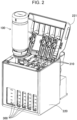
- FIG. 2 is a perspective view of the ink tanks 300 being refilled with ink supplied from the ink container 100.
- the front side of each of the ink tanks 300 is a transparent or translucent member where the amount of ink remaining ink in each of the ink tanks 300 is visible from the outside.
- the lid 221 may be opened as illustrated in FIG. 2 so that the ink tanks 300 can be refilled with ink through the respective ink inlet channel members, which are denoted by 310.
- FIG. 3 is a front view of the ink container 100 in the upright position.
- the ink container 100 in the upright position refers to the state in which the ink container 100 including a main body 10 having a bottom portion 13 is set on a horizontal surface of, for example, a desk with the bottom portion 13 facing down.
- the ink tanks 300 are each filled with ink supplied through the tip of the ink container 100 turned upside-down. Ink that is to be supplied to the ink tanks 300 is kept in the ink container 100.
- the ink container 100 includes a wetted section and a liquid-non-contact section.
- the liquid-contact section is to be in contact with ink in the ink container 100, and the liquid-non-contact section is to be kept from contact with the ink.
- the liquid-contact section is made of a virgin plastic material.
- the virgin plastic material is a new plastic material produced without other components added to it.
- the liquid-contact section is made of a virgin plastic material that does not dissolve into ink kept in the container.
- the liquid-non-contact section is made of a material containing recycled plastics. Recycled plastics are produced from waste plastics. Thus, different kinds of plastics are mixed in the recycled plastics.
- the material containing recycled plastics may be a material composed solely of recycled plastics or may be a material that is a mixture of a virgin plastic and recycled plastics.
- the liquid-contact section in the present embodiment includes the main body 10, an ink outlet portion 20, and one part of a cap 30, which are described below.
- the liquid-non-contact section is the other part of the cap 30, which is described below.
- the ink outlet portion 20 is a member coupled to the main body 10 to enable the ink to flow out of the ink container 100.
- the ink outlet portion 20 has a cylinder portion 21 with an ink outlet portion channel defined therein.
- Each ink tank 300 is refilled with ink in a state in which the corresponding ink inlet channel member 310 is inserted in the cylinder portion 21.
- a valve (not illustrated) is attached to the inside of the cylinder portion 21. The valve opens when the ink inlet channel member 310 is inserted into the cylinder portion 21. The valve closes when the ink inlet channel member 310 is removed from the cylinder portion 21.
- the ink outlet portion 20 in the present embodiment is a member separate from the main body 10.
- the ink outlet portion 20 is attached to the main body 10.
- the cap 30 is a member attached to the ink outlet portion 20.
- the cap 30 in the present embodiment covers the ink outlet portion 20 when being attached to the ink outlet portion 20.
- FIG. 4 is a perspective view of the inside of the cap 30.
- the cap 30 is a member including a first sealing portion 31, with which the ink outlet portion is sealed. With the cap 30 being attached to the ink outlet portion 20, the ink outlet portion 20 and the first sealing portion 31 are in contact with each other, in which state the first sealing portion 31 keeps ink from leaking out.
- the first sealing portion 31 is part of the liquid-contact section. This means that the first sealing portion 31 is made of a virgin plastic material.
- the cap 30 except for the first sealing portion 31 is the liquid-non-contact section. This means that the cap 30 except for the first sealing portion 31 is made of a material containing recycled plastics.
- a material containing recycled plastics that can dissolve in ink in the ink container 100 is kept from contact with the ink as described above. This eliminates or reduces the possibility that the ink container 100 will become dissolved through contact with the ink. Thus, the material concerned is less likely to have adverse effects on the ink kept in the container.
- the first sealing portion 31 is part of the liquid-contact section of the ink container 100, and the cap 30 except for the first sealing portion 31 is the liquid-non-contact section of the ink container 100.
- the material containing recycled plastics is therefore kept from contact with ink. This eliminates or reduces the possibility that the cap 30 will become dissolved through contact with ink. Thus, the material concerned is less likely to have adverse effects on the ink kept in the container.
- the identification portion 40 is disposed in at least a part of the outer surface region of the ink outlet portion 20 to enable identification of the type of ink.
- identification portions 40 of different shapes are provided for different types of ink. It is not required that the shapes of the identification portions 40 for the respective types of ink vary to the extent readily discernible to the eyes.
- each of the identification portions 40 is shaped such that it fits into a recess extending along the periphery of the ink inlet channel member 310 of the corresponding one of the ink tanks 300, in which case it is required that the shapes of the identification portions 40 for the respective types of ink vary to the extent that each identification portion 40 does not fit into the ink inlet channel members 310 of the ink tanks 300 other than the corresponding ink tank 300.
- the identification portion 40 of the ink container 100 for replenishment of yellow ink is shaped such that it fits into the recess provided for the ink tank 300 for keeping yellow ink therein, whereas the identification portion 40 of the ink container 100 for replenishment of another color ink, such as magenta ink or cyan ink, is shaped such that it does not fit into the recess provided for the ink tank 300 for keeping yellow ink therein.
- the identification portion 40 is included in the liquid-non-contact section. This means that the identification portion 40 is made of a material containing recycled plastics.
- the identification portion 40 that does not come into contact with ink is made of a material containing recycled plastics.
- the material containing recycled plastics is therefore kept from contact with ink. This eliminates or reduces the possibility that the material will become dissolved through contact with ink. Thus, the material concerned is less likely to have adverse effects on the ink kept in the container.
- FIG. 6 is a perspective view of an ink outlet portion 20C in a third embodiment.
- FIG. 7 is a perspective view of the inside of a cap 30C in the third embodiment.
- the ink outlet portion 20C includes a first engagement portion 22, and the cap 30C includes a second engagement portion 32.
- the ink container 100 according to the third embodiment is otherwise structurally identical to the ink container 100 according to the first embodiment.
- the first engagement portion 22 extends along the periphery of the ink outlet portion 20C.
- the first engagement portion 22 engages with the second engagement portion 32. That is, the ink outlet portion 20C engages with the cap 30C via the first engagement portion 22 and the second engagement portion 32.
- the concept of "engagement” herein includes not only the state in which one member engages with the other member but also the state in which one member is screwed into the other member.
- the first engagement portion 22 and the second engagement portion 32 engage with each other, with one being screwed into the other, and as a result, the ink outlet portion 20C engages with the cap 30C.
- the first engagement portion 22 and the second engagement portion 32 are included in the liquid-non-contact section. This means that the first engagement portion 22 and the second engagement portion 32 are each made of a material containing recycled plastics.
- the ink outlet portion 20C in the present embodiment includes a wall 23 in the region where the first engagement portion 22 is located.
- the wall 23 is part of the first engagement portion 22 and is included in the liquid-non-contact section.
- the outer peripheral surface of the wall 23 is a crosshatched section in FIG. 6 .
- the cap 30C in the present embodiment includes a wall 33 in the region where the second engagement portion 32 is located.
- the wall 33 is part of the second engagement portion 32 and is included in the liquid-non-contact section.
- the inner peripheral surface of the wall 33 is a crosshatched section in FIG. 7 .
- the thread in the second engagement portion 32 extends discontinuously in the circumferential direction. Alternatively, the thread may extend with no gap between one part and another part of it in the circumferential direction.
- the first engagement portion 22 and the second engagement portion 32 that do not come into contact with ink are each made of a material containing recycled plastics.
- the material containing recycled plastics is therefore kept from contact with ink. This eliminates or reduces the possibility that the material will become dissolved through contact with ink. Thus, the material concerned is less likely to have adverse effects on the ink kept in the container.
- FIG. 8 is a front view of a main body 10D in a fourth embodiment.
- FIG. 9 is a perspective view of the inside of an ink outlet portion 20D in the fourth embodiment.
- the ink container 100 according to the fourth embodiment includes a fastening mechanism 50.
- the main body 10D includes a third engagement portion 14.
- An ink outlet portion 20D includes a fourth engagement portion 24 and a second sealing portion 26.
- the ink container 100 according to the fourth embodiment is otherwise structurally identical to the ink container 100 according to the third embodiment.
- the third engagement portion 14 in the present embodiment is located between the open portion 11 and a first locking portion 51 on the outer periphery of the main body 10D.
- the fourth engagement portion 24 is located between the cylinder portion 21 and a second locking portion 52 on the inner periphery of the ink outlet portion 20D.
- the third engagement portion 14 engages with the fourth engagement portion 24. That is, the main body 10D engages with the ink outlet portion 20D via the third engagement portion 14 and the fourth engagement portion 24.
- the third engagement portion 14 and the fourth engagement portion 24 engage with each other, with one being screwed into the other, and as a result, the main body 10D engages with the ink outlet portion 20D.
- the third engagement portion 14 and the fourth engagement portion 24 are included in the liquid-non-contact section. This means that the third engagement portion 14 and the fourth engagement portion 24 are each made of a material containing recycled plastics.
- the inner peripheral surface of the ink outlet portion 20D in the present embodiment includes a tubular wall 25 in the region where the fourth engagement portion 24 is located.
- the tubular wall 25 is part of the fourth engagement portion 24 and is included in the liquid-non-contact section.
- the inner peripheral surface of the tubular wall 25 is a crosshatched section in FIG. 9 .
- the outer peripheral surface of the tubular wall 25 in the present embodiment is identical to the wall 23 (see FIG. 6 ) that is part of the first engagement portion 22.
- the inner and outer peripheral surfaces of the tubular wall 25 are both included in the liquid-non-contact section.
- the open portion 11 is sealed with the second sealing portion 26 in a state in which the third engagement portion 14 and the fourth engagement portion 24 engage with each other.
- the second sealing portion 26 is an annular protrusion.
- the open portion 11 is sealed with the annular protrusion in close contact with the inner peripheral surface of the open portion 11.
- the second sealing portion 26 thus eliminates or reduces the possibility of leakage of ink such that the third engagement portion 14 and the fourth engagement portion 24 are kept from contact with ink. It is not required that the second sealing portion 26 be in close contact with the inner peripheral surface of the open portion 11.
- the second sealing portion 26 may be in close contact with the outer peripheral surface of the open portion 11.
- the second sealing portion 26 may be in close contact with both the inner and outer peripheral surfaces of the open portion 11, in which case the tip of the open portion 11 may be sealed with the second sealing portion 26 while being caught in the second sealing portion 26.
- the second sealing portion 26 may be a packing that comes into contact with the tip face of the open portion 11.
- the fastening mechanism 50 is a mechanism for fastening the ink outlet portion 20D to the main body 10D.
- the fastening mechanism 50 includes the first locking portion 51 on the outer side of the main body 10D and the second locking portion 52 on the ink outlet portion 20.
- the fastening mechanism 50 in the present embodiment is a ratchet mechanism.
- the first locking portion 51 is a pawl included in the ratchet mechanism.
- the second locking portion 52 consists of teeth included in the ratchet mechanism. When the ink outlet portion 20 is held with the outlet open portion of the cylinder portion 21 facing upward, the second locking portion 52 is located below the second sealing portion 26 and the fourth engagement portion 24.
- the second locking portion 52 extends along the entire inner periphery of the ink outlet portion 20.
- the second locking portion 52 includes a peripheral wall where the teeth are provided. The outer peripheral surface of the peripheral wall, as well as the inner peripheral surface of the peripheral wall, may be included in the second locking portion 52.
- the ink outlet portion 20D engages with the main body 10D when the third engagement portion 14 and the fourth engagement portion 24 engage with each other, with one being screwed into the other.
- the first locking portion 51 and the second locking portion 52 engage with each other to allow rotation in one direction while preventing rotation in the opposite direction that is the unscrewing direction.
- the ink outlet portion 20D is fastened to the main body 10D.
- the first locking portion 51 and the second locking portion 52 are located on the outer side of the main body 10D. That is, the fastening mechanism 50 is located on the outer side of the main body 10D in the state in which the ink outlet portion 20D is fastened to the main body 10D by the fastening mechanism 50.
- the fastening mechanism 50 is thus included in the liquid-non-contact section. This means that the fastening mechanism 50 is made of a material containing recycled plastics. It is not required that the fastening mechanism 50 be a ratchet mechanism. For example, the fastening mechanism 50 may be a snap-fit.
- the fastening mechanism 50 that does not come into contact with ink is made of a material containing recycled plastics.
- the material containing recycled plastics is therefore kept from contact with ink. This eliminates or reduces the possibility that the material will become dissolved through contact with ink. Thus, the material concerned is less likely to have adverse effects on the ink kept in the container.
- the third engagement portion 14 and the fourth engagement portion 24 that do not come into contact with ink are each made of a material containing recycled plastics.
- the material containing recycled plastics is therefore kept from contact with ink. This eliminates or reduces the possibility that the material will become dissolved through contact with ink. Thus, the material concerned is less likely to have adverse effects on the ink kept in the container.
- FIG. 10 is a sectional view of a main body 10E in a fifth embodiment.
- a surface layer 12b as a first outer layer of the side portion 12 is included in the liquid-non-contact section.
- the ink container 100 according to the fifth embodiment is otherwise structurally identical to the ink container 100 according to the first embodiment.
- the term “surface layer” herein refers to an outer layer facing outward.
- the term “inner layer” herein refers to a layer facing the interior of the ink container 100.
- the side portion 12 in the present embodiment is a double-layer structure composed of an inner layer 12a and the surface layer 12b.
- the inner layer 12a is made of a virgin plastic material
- the surface layer 12b is made of a material containing recycled plastics.
- the ink container 100 according to the fifth embodiment in which the side portion 12 is a double-layer structure as described above is tougher than it would be if the side portion 12 were a single-layer structure. This eliminates or reduces the possibility that the force applied to the side portion 12 at the time when the user holds the ink container will cause the ink container to become deformed or will cause ink from spurting out of the container. Furthermore, the proportion of the material containing recycled plastics in the ink container is higher than it would be if the lamination were made solely of a virgin plastic material.
- FIG. 11 is a sectional view of a main body 10F in a sixth embodiment.
- a surface layer 13b as a second outer layer of the bottom portion 13 is included in the liquid-non-contact section.
- the ink container 100 according to the sixth embodiment is otherwise structurally identical to the ink container 100 according to the fifth embodiment.
- the bottom portion 13 in the present embodiment is a double-layer structure composed of an inner layer 13a and the surface layer 13b.
- the inner layer 13a is made of a virgin plastic material
- the surface layer 13b is made of a material containing recycled plastics.
- the surface layer 13b of the bottom portion 13 and the surface layer 12b of the side portion 12 extend without a gap therebetween.
- the ink container 100 according to the sixth embodiment in which the bottom portion 13 is a double-layer structure as described above is tougher than it would be if the bottom portion 13 were a single-layer structure.
- the main body 10 is reinforced at corners where the bottom portion 13 and the side portion 12 are coupled to each other; otherwise, the main body 10 would be likely to become thinned at the corners especially when being formed by blow molding.
- the proportion of the material containing recycled plastics in the ink container is higher than it would be if the lamination were made solely of a virgin plastic material.
- the main body 10 of the ink container 100 may bear a label on its periphery, where the label may be part of the liquid-non-contact section.
- the liquid-contact section and the liquid-non-contact section in the embodiment described above may be formed as a one-piece member or a combination of separate members.
- the liquid-contact section and the liquid-non-contact section are separate members, it is preferable that they be combined together without an adhesive.
- the main body 10 and the ink outlet portion 20 in any one of the first embodiment, the second embodiment, the third embodiment, the fifth embodiment, and the sixth embodiment may constitute a single undivided piece.
- identification portions 40 of different shapes are provided for different types of ink.
- identification portions 40 of different colors are provided for different types of ink.
- the color of each identification portion 40 is consistent with the color of the ink kept in the container. In this case, the color of the ink kept in the container is readily discernible to the eyes.
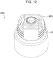
- an identification portion 40G may extend either along part of or all along the periphery of an ink outlet portion 20G.
- the identification portion 40G may include a fifth engagement portion 41, which engages with the cap 30.
- the fifth engagement portion 41 is associated with the first engagement portion 22 illustrated in FIG. 6 .
- the ink container 100 includes the fastening mechanism 50, the third engagement portion 14, the fourth engagement portion 24, and the second sealing portion 26.
- the fastening mechanism 50 of the ink container 100 may be provided alone; that is, the third engagement portion 14 and the fourth engagement portion 24 are optional. It is not required that the ink container 100 include the fastening mechanism 50.
- the side portion 12 is a double-layer structure.
- the side portion 12 may be a multilayer structure composed of three or more layers.
- the bottom portion 13 is a double-layer structure.
- the bottom portion 13 may be a multilayer structure composed of three or more layers. It is not required that both the side portion 12 and the bottom portion 13 be multilayer structures; that is, only the bottom portion 13 may be a multilayer structure.
- the entirety of the surface layer 12b of the side portion 12 is included in the liquid-non-contact section.
- at least part of the surface layer 12b of the side portion 12 may be included in the liquid-non-contact section.
- the entirety of the wall of the ink outlet portion 20 in the first embodiment described above may be a lamination composed of an inner layer and a surface layer.
- part of the ink outlet portion 20 or, more specifically, the wall of the cylinder portion 21 having an ink outlet portion channel defined therein may be a lamination composed of an inner layer and a surface layer.
- the wall may be formed by, for example, dual-material molding using mutually different materials.
- the inner layer included in the liquid-contact section may be made of a virgin polypropylene material
- the surface layer included in the liquid-non-contact section may be made of recycled plastics other than polypropylene.
- the main body 10E in the fifth embodiment and the main body 10F in the sixth embodiment each may be formed by, for example, dual-material molding, in which case the inner layer may be made of a virgin polypropylene material, and the surface layer may be made of a material containing recycled plastics other than polypropylene. Furthermore, the ink outlet portion 20 and the main body 10 may be molded in one piece in the manner described above.
- the present disclosure can also be implemented as, for example, a method for manufacturing ink containers.
Landscapes
- Engineering & Computer Science (AREA)
- Manufacturing & Machinery (AREA)
- Ink Jet (AREA)
Abstract
An ink container (100) includes a liquid-contact section and a liquid-non-contact section. The liquid-contact section is made of a virgin plastic material and is to be in contact with ink in the ink container. The liquid-non-contact section is made of a material containing recycled plastics and is to be kept from contact with the ink.
Description
- The present application is based on, and claims priority from
JP Application Serial Number 2023-178714, filed October 17, 2023 - The present disclosure relates to techniques concerning ink containers.
- Ink-refill ink jet printers equipped with refillable ink tanks are known. An ink container disclosed in
JP-A-2022-18712 - In recent years, there has been a demand for ink containers made of recycled plastics, which are preferred from the viewpoint of a recycling-oriented society. However, it is difficult to determine the composition of recycled plastics obtained by reprocessing waste plastics in which different kinds of plastics are mixed. The inventors have found that such an ink container made of recycled plastics can dissolve into the ink kept therein and can therefore affect the ink.
- According to an aspect of the present disclosure, an ink container is provided. The ink container includes a liquid-contact section and a liquid-non-contact section. The liquid-contact section is made of a virgin plastic material and is to be in contact with ink in the ink container. The liquid-non-contact section is made of a material containing recycled plastics and is to be kept from contact with the ink.
-
-
FIG. 1 is a perspective view of a printer. -
FIG. 2 is a perspective view of ink tanks being refilled with ink supplied from an ink container. -
FIG. 3 is a front view of the ink container in the upright position. -
FIG. 4 is a perspective view of the inside of a cap. -
FIG. 5 is a perspective view of an ink outlet portion in a second embodiment. -
FIG. 6 is a perspective view of an ink outlet portion in a third embodiment. -
FIG. 7 is a perspective view of the inside of a cap in the third embodiment. -
FIG. 8 is a front view of a main body in a fourth embodiment. -
FIG. 9 is a perspective view of the inside of an ink outlet portion in a fourth embodiment. -
FIG. 10 is a sectional view of a main body in a fifth embodiment. -
FIG. 11 is a sectional view of a main body in a sixth embodiment. -
FIG. 12 is a perspective view of a variation of the ink outlet portion. -
FIG. 1 is a perspective view of aprinter 200 according to the present embodiment. Theprinter 200 is an ink jet printer that performs printing by ejecting ink onto a printing medium. X, Y, and Z inFIG. 1 denote axes that are orthogonal to each other. The X-axis coincides with the width direction of theprinter 200. The Y-axis coincides with the depth direction of theprinter 200. The Z-axis coincides with the height direction of theprinter 200. Theprinter 200 is installed on a horizontal plane defined by the X-axis direction and the Y-axis direction. These axes inFIG. 1 coincide with the respective axes inFIG. 3 . - The
printer 200 includes ahousing 210. Thehousing 210 accommodates a carriage (not illustrated) capable of moving in the primary scanning direction (the X-axis direction). The carriage is equipped with a print head from which ink is ejected and sprayed onto a printing medium. An inktank housing unit 220, in whichink tanks 300 are housed, is located in an end portion of the front side of thehousing 210. The inktank housing unit 220 is fitted with alid 221, which can be opened and closed at the top of the inktank housing unit 220. Theink tanks 300 are refillable ink tanks, each of which is to be refilled with ink kept in anink container 100 when the ink level is low. -
FIG. 2 is a perspective view of theink tanks 300 being refilled with ink supplied from theink container 100. The front side of each of theink tanks 300 is a transparent or translucent member where the amount of ink remaining ink in each of theink tanks 300 is visible from the outside. When the ink level is low, thelid 221 may be opened as illustrated inFIG. 2 so that theink tanks 300 can be refilled with ink through the respective ink inlet channel members, which are denoted by 310. -
FIG. 3 is a front view of theink container 100 in the upright position. Theink container 100 in the upright position refers to the state in which theink container 100 including amain body 10 having abottom portion 13 is set on a horizontal surface of, for example, a desk with thebottom portion 13 facing down. As illustrated inFIG. 2 mentioned above, theink tanks 300 are each filled with ink supplied through the tip of theink container 100 turned upside-down. Ink that is to be supplied to theink tanks 300 is kept in theink container 100. - The
ink container 100 includes a wetted section and a liquid-non-contact section. The liquid-contact section is to be in contact with ink in theink container 100, and the liquid-non-contact section is to be kept from contact with the ink. The liquid-contact section is made of a virgin plastic material. The virgin plastic material is a new plastic material produced without other components added to it. The liquid-contact section is made of a virgin plastic material that does not dissolve into ink kept in the container. The liquid-non-contact section is made of a material containing recycled plastics. Recycled plastics are produced from waste plastics. Thus, different kinds of plastics are mixed in the recycled plastics. The material containing recycled plastics may be a material composed solely of recycled plastics or may be a material that is a mixture of a virgin plastic and recycled plastics. The liquid-contact section in the present embodiment includes themain body 10, anink outlet portion 20, and one part of acap 30, which are described below. The liquid-non-contact section is the other part of thecap 30, which is described below. - The
ink container 100 in the present embodiment includes themain body 10, theink outlet portion 20, and thecap 30. Themain body 10 is a member in which ink can be kept. Themain body 10 is a member that defines the shape of a cylindrical bottle and has anopen portion 11, thebottom portion 13, and aside portion 12. Theopen portion 11 is linked to theink outlet portion 20. Theopen portion 11 and thebottom portion 13 are coupled to each other with theside portion 12 extending therebetween. - The
ink outlet portion 20 is a member coupled to themain body 10 to enable the ink to flow out of theink container 100. Theink outlet portion 20 has acylinder portion 21 with an ink outlet portion channel defined therein. Eachink tank 300 is refilled with ink in a state in which the corresponding inkinlet channel member 310 is inserted in thecylinder portion 21. A valve (not illustrated) is attached to the inside of thecylinder portion 21. The valve opens when the inkinlet channel member 310 is inserted into thecylinder portion 21. The valve closes when the inkinlet channel member 310 is removed from thecylinder portion 21. Theink outlet portion 20 in the present embodiment is a member separate from themain body 10. Theink outlet portion 20 is attached to themain body 10. Thecap 30 is a member attached to theink outlet portion 20. Thecap 30 in the present embodiment covers theink outlet portion 20 when being attached to theink outlet portion 20. -
FIG. 4 is a perspective view of the inside of thecap 30. Thecap 30 is a member including afirst sealing portion 31, with which the ink outlet portion is sealed. With thecap 30 being attached to theink outlet portion 20, theink outlet portion 20 and thefirst sealing portion 31 are in contact with each other, in which state thefirst sealing portion 31 keeps ink from leaking out. Thefirst sealing portion 31 is part of the liquid-contact section. This means that thefirst sealing portion 31 is made of a virgin plastic material. Thecap 30 except for thefirst sealing portion 31 is the liquid-non-contact section. This means that thecap 30 except for thefirst sealing portion 31 is made of a material containing recycled plastics. - In the present embodiment, a material containing recycled plastics that can dissolve in ink in the
ink container 100 is kept from contact with the ink as described above. This eliminates or reduces the possibility that theink container 100 will become dissolved through contact with the ink. Thus, the material concerned is less likely to have adverse effects on the ink kept in the container. - The
first sealing portion 31 is part of the liquid-contact section of theink container 100, and thecap 30 except for thefirst sealing portion 31 is the liquid-non-contact section of theink container 100. The material containing recycled plastics is therefore kept from contact with ink. This eliminates or reduces the possibility that thecap 30 will become dissolved through contact with ink. Thus, the material concerned is less likely to have adverse effects on the ink kept in the container. -
FIG. 5 is a perspective view of anink outlet portion 20B in a second embodiment. Theink outlet portion 20B includes anidentification portion 40. Theink container 100 according to the second embodiment is otherwise structurally identical to theink container 100 according to the first embodiment. - The
identification portion 40 is disposed in at least a part of the outer surface region of theink outlet portion 20 to enable identification of the type of ink. In the present embodiment,identification portions 40 of different shapes are provided for different types of ink. It is not required that the shapes of theidentification portions 40 for the respective types of ink vary to the extent readily discernible to the eyes. For example, each of theidentification portions 40 is shaped such that it fits into a recess extending along the periphery of the inkinlet channel member 310 of the corresponding one of theink tanks 300, in which case it is required that the shapes of theidentification portions 40 for the respective types of ink vary to the extent that eachidentification portion 40 does not fit into the inkinlet channel members 310 of theink tanks 300 other than the correspondingink tank 300. More specifically, theidentification portion 40 of theink container 100 for replenishment of yellow ink is shaped such that it fits into the recess provided for theink tank 300 for keeping yellow ink therein, whereas theidentification portion 40 of theink container 100 for replenishment of another color ink, such as magenta ink or cyan ink, is shaped such that it does not fit into the recess provided for theink tank 300 for keeping yellow ink therein. Theidentification portion 40 is included in the liquid-non-contact section. This means that theidentification portion 40 is made of a material containing recycled plastics. - In the
ink container 100 according to the second embodiment described above, theidentification portion 40 that does not come into contact with ink is made of a material containing recycled plastics. The material containing recycled plastics is therefore kept from contact with ink. This eliminates or reduces the possibility that the material will become dissolved through contact with ink. Thus, the material concerned is less likely to have adverse effects on the ink kept in the container. -
FIG. 6 is a perspective view of anink outlet portion 20C in a third embodiment.FIG. 7 is a perspective view of the inside of acap 30C in the third embodiment. Theink outlet portion 20C includes afirst engagement portion 22, and thecap 30C includes a second engagement portion 32. Theink container 100 according to the third embodiment is otherwise structurally identical to theink container 100 according to the first embodiment. - The
first engagement portion 22 extends along the periphery of theink outlet portion 20C. Thefirst engagement portion 22 engages with the second engagement portion 32. That is, theink outlet portion 20C engages with thecap 30C via thefirst engagement portion 22 and the second engagement portion 32. The concept of "engagement" herein includes not only the state in which one member engages with the other member but also the state in which one member is screwed into the other member. In the present embodiment, thefirst engagement portion 22 and the second engagement portion 32 engage with each other, with one being screwed into the other, and as a result, theink outlet portion 20C engages with thecap 30C. Thefirst engagement portion 22 and the second engagement portion 32 are included in the liquid-non-contact section. This means that thefirst engagement portion 22 and the second engagement portion 32 are each made of a material containing recycled plastics. - The
ink outlet portion 20C in the present embodiment includes awall 23 in the region where thefirst engagement portion 22 is located. Thewall 23 is part of thefirst engagement portion 22 and is included in the liquid-non-contact section. The outer peripheral surface of thewall 23 is a crosshatched section inFIG. 6 . - The
cap 30C in the present embodiment includes a wall 33 in the region where the second engagement portion 32 is located. The wall 33 is part of the second engagement portion 32 and is included in the liquid-non-contact section. The inner peripheral surface of the wall 33 is a crosshatched section inFIG. 7 . The thread in the second engagement portion 32 extends discontinuously in the circumferential direction. Alternatively, the thread may extend with no gap between one part and another part of it in the circumferential direction. - In the
ink container 100 according to the third embodiment described above, thefirst engagement portion 22 and the second engagement portion 32 that do not come into contact with ink are each made of a material containing recycled plastics. The material containing recycled plastics is therefore kept from contact with ink. This eliminates or reduces the possibility that the material will become dissolved through contact with ink. Thus, the material concerned is less likely to have adverse effects on the ink kept in the container. -
FIG. 8 is a front view of amain body 10D in a fourth embodiment.FIG. 9 is a perspective view of the inside of anink outlet portion 20D in the fourth embodiment. Theink container 100 according to the fourth embodiment includes a fastening mechanism 50. Themain body 10D includes athird engagement portion 14. Anink outlet portion 20D includes afourth engagement portion 24 and asecond sealing portion 26. Theink container 100 according to the fourth embodiment is otherwise structurally identical to theink container 100 according to the third embodiment. - The
third engagement portion 14 in the present embodiment is located between theopen portion 11 and a first locking portion 51 on the outer periphery of themain body 10D. Thefourth engagement portion 24 is located between thecylinder portion 21 and a second locking portion 52 on the inner periphery of theink outlet portion 20D. Thethird engagement portion 14 engages with thefourth engagement portion 24. That is, themain body 10D engages with theink outlet portion 20D via thethird engagement portion 14 and thefourth engagement portion 24. In the present embodiment, thethird engagement portion 14 and thefourth engagement portion 24 engage with each other, with one being screwed into the other, and as a result, themain body 10D engages with theink outlet portion 20D. Thethird engagement portion 14 and thefourth engagement portion 24 are included in the liquid-non-contact section. This means that thethird engagement portion 14 and thefourth engagement portion 24 are each made of a material containing recycled plastics. - The inner peripheral surface of the
ink outlet portion 20D in the present embodiment includes a tubular wall 25 in the region where thefourth engagement portion 24 is located. The tubular wall 25 is part of thefourth engagement portion 24 and is included in the liquid-non-contact section. The inner peripheral surface of the tubular wall 25 is a crosshatched section inFIG. 9 . The outer peripheral surface of the tubular wall 25 in the present embodiment is identical to the wall 23 (seeFIG. 6 ) that is part of thefirst engagement portion 22. The inner and outer peripheral surfaces of the tubular wall 25 are both included in the liquid-non-contact section. - The
open portion 11 is sealed with thesecond sealing portion 26 in a state in which thethird engagement portion 14 and thefourth engagement portion 24 engage with each other. Thesecond sealing portion 26 is an annular protrusion. Theopen portion 11 is sealed with the annular protrusion in close contact with the inner peripheral surface of theopen portion 11. Thesecond sealing portion 26 thus eliminates or reduces the possibility of leakage of ink such that thethird engagement portion 14 and thefourth engagement portion 24 are kept from contact with ink. It is not required that thesecond sealing portion 26 be in close contact with the inner peripheral surface of theopen portion 11. Thesecond sealing portion 26 may be in close contact with the outer peripheral surface of theopen portion 11. Alternatively, thesecond sealing portion 26 may be in close contact with both the inner and outer peripheral surfaces of theopen portion 11, in which case the tip of theopen portion 11 may be sealed with thesecond sealing portion 26 while being caught in thesecond sealing portion 26. Instead of being an annular protrusion, thesecond sealing portion 26 may be a packing that comes into contact with the tip face of theopen portion 11. - The fastening mechanism 50 is a mechanism for fastening the
ink outlet portion 20D to themain body 10D. The fastening mechanism 50 includes the first locking portion 51 on the outer side of themain body 10D and the second locking portion 52 on theink outlet portion 20. The fastening mechanism 50 in the present embodiment is a ratchet mechanism. The first locking portion 51 is a pawl included in the ratchet mechanism. The second locking portion 52 consists of teeth included in the ratchet mechanism. When theink outlet portion 20 is held with the outlet open portion of thecylinder portion 21 facing upward, the second locking portion 52 is located below thesecond sealing portion 26 and thefourth engagement portion 24. The second locking portion 52 extends along the entire inner periphery of theink outlet portion 20. The second locking portion 52 includes a peripheral wall where the teeth are provided. The outer peripheral surface of the peripheral wall, as well as the inner peripheral surface of the peripheral wall, may be included in the second locking portion 52. - In the present embodiment, the
ink outlet portion 20D engages with themain body 10D when thethird engagement portion 14 and thefourth engagement portion 24 engage with each other, with one being screwed into the other. As a result, the first locking portion 51 and the second locking portion 52 engage with each other to allow rotation in one direction while preventing rotation in the opposite direction that is the unscrewing direction. In this way, theink outlet portion 20D is fastened to themain body 10D. In the fastened state, the first locking portion 51 and the second locking portion 52 are located on the outer side of themain body 10D. That is, the fastening mechanism 50 is located on the outer side of themain body 10D in the state in which theink outlet portion 20D is fastened to themain body 10D by the fastening mechanism 50. The fastening mechanism 50 is thus included in the liquid-non-contact section. This means that the fastening mechanism 50 is made of a material containing recycled plastics. It is not required that the fastening mechanism 50 be a ratchet mechanism. For example, the fastening mechanism 50 may be a snap-fit. - In the
ink container 100 according to the fourth embodiment described above, the fastening mechanism 50 that does not come into contact with ink is made of a material containing recycled plastics. The material containing recycled plastics is therefore kept from contact with ink. This eliminates or reduces the possibility that the material will become dissolved through contact with ink. Thus, the material concerned is less likely to have adverse effects on the ink kept in the container. - Furthermore, the
third engagement portion 14 and thefourth engagement portion 24 that do not come into contact with ink are each made of a material containing recycled plastics. The material containing recycled plastics is therefore kept from contact with ink. This eliminates or reduces the possibility that the material will become dissolved through contact with ink. Thus, the material concerned is less likely to have adverse effects on the ink kept in the container. -
FIG. 10 is a sectional view of amain body 10E in a fifth embodiment. Asurface layer 12b as a first outer layer of theside portion 12 is included in the liquid-non-contact section. Theink container 100 according to the fifth embodiment is otherwise structurally identical to theink container 100 according to the first embodiment. The term "surface layer" herein refers to an outer layer facing outward. Conversely, the term "inner layer" herein refers to a layer facing the interior of theink container 100. - The
side portion 12 in the present embodiment is a double-layer structure composed of aninner layer 12a and thesurface layer 12b. Theinner layer 12a is made of a virgin plastic material, whereas thesurface layer 12b is made of a material containing recycled plastics. - The
ink container 100 according to the fifth embodiment in which theside portion 12 is a double-layer structure as described above is tougher than it would be if theside portion 12 were a single-layer structure. This eliminates or reduces the possibility that the force applied to theside portion 12 at the time when the user holds the ink container will cause the ink container to become deformed or will cause ink from spurting out of the container. Furthermore, the proportion of the material containing recycled plastics in the ink container is higher than it would be if the lamination were made solely of a virgin plastic material. -
FIG. 11 is a sectional view of amain body 10F in a sixth embodiment. Asurface layer 13b as a second outer layer of thebottom portion 13 is included in the liquid-non-contact section. Theink container 100 according to the sixth embodiment is otherwise structurally identical to theink container 100 according to the fifth embodiment. - The
bottom portion 13 in the present embodiment is a double-layer structure composed of aninner layer 13a and thesurface layer 13b. Theinner layer 13a is made of a virgin plastic material, whereas thesurface layer 13b is made of a material containing recycled plastics. Thesurface layer 13b of thebottom portion 13 and thesurface layer 12b of theside portion 12 extend without a gap therebetween. - The
ink container 100 according to the sixth embodiment in which thebottom portion 13 is a double-layer structure as described above is tougher than it would be if thebottom portion 13 were a single-layer structure. In addition, themain body 10 is reinforced at corners where thebottom portion 13 and theside portion 12 are coupled to each other; otherwise, themain body 10 would be likely to become thinned at the corners especially when being formed by blow molding. Furthermore, the proportion of the material containing recycled plastics in the ink container is higher than it would be if the lamination were made solely of a virgin plastic material. - (G1) The
main body 10 of theink container 100 according to the embodiment described above may bear a label on its periphery, where the label may be part of the liquid-non-contact section. - (G2) The liquid-contact section and the liquid-non-contact section in the embodiment described above may be formed as a one-piece member or a combination of separate members. When the liquid-contact section and the liquid-non-contact section are separate members, it is preferable that they be combined together without an adhesive.
- (G3) The
main body 10 and theink outlet portion 20 in any one of the first embodiment, the second embodiment, the third embodiment, the fifth embodiment, and the sixth embodiment may constitute a single undivided piece. - (G4) It is not required that the
ink container 100 according to any one of the second embodiment, the fourth embodiment, the fifth embodiment, and the sixth embodiment be fitted with thecap 30. - (G5) In the second embodiment,
identification portions 40 of different shapes are provided for different types of ink. In some embodiments,identification portions 40 of different colors are provided for different types of ink. For example, the color of eachidentification portion 40 is consistent with the color of the ink kept in the container. In this case, the color of the ink kept in the container is readily discernible to the eyes. - (G6) As illustrated in
FIG. 12 in relation to the second embodiment described above, anidentification portion 40G may extend either along part of or all along the periphery of anink outlet portion 20G. Theidentification portion 40G may include afifth engagement portion 41, which engages with thecap 30. Thefifth engagement portion 41 is associated with thefirst engagement portion 22 illustrated inFIG. 6 . - (G7) The
ink container 100 according to the fourth embodiment described above includes the fastening mechanism 50, thethird engagement portion 14, thefourth engagement portion 24, and thesecond sealing portion 26. Alternatively, the fastening mechanism 50 of theink container 100 may be provided alone; that is, thethird engagement portion 14 and thefourth engagement portion 24 are optional. It is not required that theink container 100 include the fastening mechanism 50. - (G8) In both the fifth and sixth embodiments described above, the
side portion 12 is a double-layer structure. Alternatively, theside portion 12 may be a multilayer structure composed of three or more layers. In the sixth embodiment described above, thebottom portion 13 is a double-layer structure. Alternatively, thebottom portion 13 may be a multilayer structure composed of three or more layers. It is not required that both theside portion 12 and thebottom portion 13 be multilayer structures; that is, only thebottom portion 13 may be a multilayer structure. - (G9) In both the fifth and sixth embodiments described above, the entirety of the
surface layer 12b of theside portion 12 is included in the liquid-non-contact section. Alternatively, at least part of thesurface layer 12b of theside portion 12 may be included in the liquid-non-contact section. - (G10) The entirety of the wall of the
ink outlet portion 20 in the first embodiment described above may be a lamination composed of an inner layer and a surface layer. The same holds true for the second embodiment, the third embodiment, the fifth embodiment, and the sixth embodiment. Alternatively, part of theink outlet portion 20 or, more specifically, the wall of thecylinder portion 21 having an ink outlet portion channel defined therein may be a lamination composed of an inner layer and a surface layer. The wall may be formed by, for example, dual-material molding using mutually different materials. For example, the inner layer included in the liquid-contact section may be made of a virgin polypropylene material, and the surface layer included in the liquid-non-contact section may be made of recycled plastics other than polypropylene. Themain body 10E in the fifth embodiment and themain body 10F in the sixth embodiment each may be formed by, for example, dual-material molding, in which case the inner layer may be made of a virgin polypropylene material, and the surface layer may be made of a material containing recycled plastics other than polypropylene. Furthermore, theink outlet portion 20 and themain body 10 may be molded in one piece in the manner described above. - The present disclosure is not limited to the embodiments described above and may be implemented in various forms within a range not departing from the spirit of the present disclosure. For example, the technical features of each embodiment that correspond to the respective technical features described as each aspect in the summary can be interchanged or combined as appropriate to solve some or all of the aforementioned problems or to achieve some or all of the aforementioned effects. Any of the technical features that is not herein described as an absolute must may be omitted where appropriate.
- (1) According to an embodiment of the present disclosure, an ink container is provided. The ink container includes a liquid-contact section and a liquid-non-contact section. The liquid-contact section is made of a virgin plastic material and is to be in contact with ink in the ink container. The liquid-non-contact section is made of a material containing recycled plastics and is to be kept from contact with the ink. The embodiment in which a material containing recycled plastics that can dissolve in ink is kept from contact with ink eliminates or reduces the possibility that the ink container will become dissolved through contact with ink.
- (2) The ink container according to the embodiment described above may further include: a main body configured to keep the ink therein; an ink outlet portion linked to the main body to enable the ink to flow out of the ink container; and a cap including a first sealing portion with which the ink outlet portion is sealed. The first sealing portion may be part of the liquid-contact section, and the cap except for the first sealing portion may be part or all of the liquid-non-contact section. When the first sealing portion is part of the liquid-contact section, and the cap except for the first sealing portion is part or all of the liquid-non-contact section, the material containing recycled plastics is kept from contact with ink. The ink container according to the present embodiment therefore eliminates or reduces the possibility that the cap will become dissolved through contact with ink. Thus, the material concerned is less likely to have adverse effects on the ink kept in the container.
- (3) The ink container according to the embodiment described above may further include: a main body configured to keep the ink therein; an ink outlet portion linked to the main body to enable the ink to flow out of the ink container; and an identification portion that is disposed in at least a part of an outer surface region of the ink outlet portion to enable identification of a type of the ink and that is part or all of the liquid-non-contact section. In the ink container according to the present embodiment, the identification portion that does not come into contact with ink is made of a material containing recycled plastics. The material containing recycled plastics is therefore kept from contact with ink. This eliminates or reduces the possibility that the material will become dissolved through contact with ink. Thus, the material concerned is less likely to have adverse effects on the ink kept in the container.
- (4) The ink container according to the embodiment described above may further include: a main body configured to keep the ink therein; an ink outlet portion linked to the main body to enable the ink to flow out of the ink container; and a cap configured to be attached to the ink outlet portion. The ink outlet portion may include a first engagement portion that extends along at least part of a periphery of the ink outlet portion and that is part or all of the liquid-non-contact section. The cap may include a second engagement portion that is configured to be engaged with the first engagement portion and that is part or all of the liquid-non-contact section. In the ink container according to the present embodiment, the first engagement portion and the second engagement portion that do not come into contact with ink are each made of a material containing recycled plastics. The material containing recycled plastics is therefore kept from contact with ink. This eliminates or reduces the possibility that the material will become dissolved through contact with ink. Thus, the material concerned is less likely to have adverse effects on the ink kept in the container.
- (5) The ink container according to the embodiment described above may further include: a main body configured to keep the ink therein; an ink outlet portion that is separate from the main body and that is linked to the main body to enable the ink to flow out of the ink container; and a fastening mechanism configured to fasten the ink outlet portion to the main body. The fastening mechanism may include a first locking portion disposed on an outer side of the main body and a second locking portion that is disposed on the ink outlet portion and that is configured to be engaged with the first locking portion. The second locking portion may be located on the outer side of the main body in a fastened state in which the ink outlet portion is fastened to the main body with the first and second locking portions engaged with each other. The fastening mechanism may be part or all of the liquid-non-contact section. In the ink container according to the present embodiment, the fastening mechanism that does not come into contact with ink is made of a material containing recycled plastics. The material containing recycled plastics is therefore kept from contact with ink. This eliminates or reduces the possibility that the material will become dissolved through contact with ink. Thus, the material concerned is less likely to have adverse effects on the ink kept in the container.
- (6) The ink container according to the embodiment described above may further include: a main body configured to keep the ink therein; and an ink outlet portion that is separate from and removably attached to the main body and that is linked to the main body to enable the ink to flow out of the ink container. The main body may include an open portion linked to the ink outlet portion and a third engagement portion that is located on an outer side of the main body and that is part or all of the liquid-non-contact section. The ink outlet portion may include: a fourth engagement portion that is configured to be engaged with the third engagement portion and that is part or all of the liquid-non-contact section; and a second sealing portion with which the open portion is sealed in a state in which the third engagement portion and the fourth engagement portion engage with each other. In the ink container according to the present embodiment, the third engagement portion and the fourth engagement portion that do not come into contact with ink are each made of a material containing recycled plastics. The material containing recycled plastics is therefore kept from contact with ink. This eliminates or reduces the possibility that the material will become dissolved through contact with ink. Thus, the material concerned is less likely to have adverse effects on the ink kept in the container.
- (7) The ink container according to the embodiment described above may further comprise: a main body configured to keep the ink therein; and an ink outlet portion linked to the main body to enable the ink to flow out of the ink container. The main body may have a bottom portion and a side portion. The ink outlet portion and the bottom portion may be coupled to each other with the side portion extending therebetween. At least a part of the side portion may have a wall of a plurality of layers, one layer of which is a first outer layer facing outward. The first outer layer may constitute part or all of the liquid-non-contact section. The ink container according to the present embodiment in which at least a part of the side portion having a wall of a plurality of layers is tougher than it would be if the side portion were a single-layer structure.
- (8) The ink container according to the embodiment described above may further comprise: a main body configured to keep the ink therein; and an ink outlet portion linked to the main body to enable the ink to flow out of the ink container. The main body may have a bottom portion and a side portion. The ink outlet portion and the bottom portion may be coupled to each other with the side portion extending therebetween. At least a part of the bottom portion may have a wall of a plurality of layers, one layer of which is a second outer layer facing outward. The second outer layer may constitute part or all of the liquid-non-contact section. The ink container according to the present embodiment in which at least a part of the bottom portion having a wall of a plurality of layers is tougher than it would be if the bottom portion were a single-layer structure.
- (9) The ink container according to the embodiment described above may further comprise: a main body configured to keep the ink therein; and an ink outlet portion linked to the main body to enable the ink to flow out of the ink container. The main body may have a bottom portion and a side portion. The ink outlet portion and the bottom portion may be coupled to each other with the side portion extending therebetween. At least a part of the side portion may have a wall of a plurality of layers, one layer of which is a first outer layer facing outward. At least a part of the bottom portion may have a wall of a plurality of layers, one layer of which is a second outer layer facing outward. The first and second outer layers may be continuous with each other and may constitute part or all of the liquid-non-contact section. The ink container according to the present embodiment is tougher than it would be if the side and bottom portions were a single-layer structure.
- (10) The liquid-contact section and the liquid-non-contact section of the ink container according to the embodiment described above may be unitarily formed, that is, formed as a one-piece member or a combination of separate members. That is, the liquid-contact section and the liquid-non-contact section of the ink container according to the present embodiment can be formed as either a one-piece member or a combination of separate members. For example, the liquid-contact section and the liquid-non-contact section may be formed as a one-piece member by dual-material molding. Alternatively, the liquid-contact section and the liquid-non-contact section may be formed by combining separate members by means of, for example, adhesion, staking, or engagement. The separate members detachably combined together by means of, for example, staking or engagement are replaceable and recyclable. For example, the fastening member can restore its fastening function through the replacement of a worn-out member with a new one.
- Not all of the constituent components mentioned above in relation to each of the embodiments of the present disclosure are essential. Some of the constituent components may be changed, omitted, replaced with newly adopted components, or freed from some of the limitations to solve some or all of the aforementioned problems or to achieve some or all of the effects described herein. For example, some or all of the technical features of one embodiment of the present disclosure described above and some or all of the technical features of another embodiment of the present disclosure described above may be combined into an independent embodiment of the present disclosure to solve some or all of the aforementioned problems or to achieve some or all of the effects described herein.
- While the embodiments of the present disclosure have been described above, the present disclosure can also be implemented as, for example, a method for manufacturing ink containers.
Claims (10)
- An ink container comprising:a liquid-contact section that is made of a virgin plastic material and that is to be in contact with ink in the ink container; anda liquid-non-contact section that is made of a material containing recycled plastics and that is to be kept from contact with the ink.
- The ink container according to claim 1, further comprising:a main body configured to keep the ink therein;an ink outlet portion linked to the main body to enable the ink to flow out of the ink container; anda cap including a first sealing portion with which the ink outlet portion is sealed, whereinthe first sealing portion is part of the liquid-contact section, andthe cap except for the first sealing portion is part or all of the liquid-non-contact section.
- The ink container according to claim 1, further comprising:a main body configured to keep the ink therein;an ink outlet portion linked to the main body to enable the ink to flow out of the ink container; andan identification portion that is disposed in at least a part of an outer surface region of the ink outlet portion to enable identification of a type of the ink and that is part or all of the liquid-non-contact section.
- The ink container according to claim 1, further comprising:a main body configured to keep the ink therein;an ink outlet portion linked to the main body to enable the ink to flow out of the ink container; anda cap configured to be attached to the ink outlet portion, whereinthe ink outlet portion includes a first engagement portion that extends along at least part of a periphery of the ink outlet portion and that is part or all of the liquid-non-contact section, andthe cap includes a second engagement portion that is configured to be engaged with the first engagement portion and that is part or all of the liquid-non-contact section.
- The ink container according to claim 1, further comprising:a main body configured to keep the ink therein;an ink outlet portion that is separate from the main body and that is linked to the main body to enable the ink to flow out of the ink container; anda fastening mechanism configured to fasten the ink outlet portion to the main body, whereinthe fastening mechanism includesa first locking portion disposed on an outer side of the main body, anda second locking portion that is disposed on the ink outlet portion and that is configured to engage with the first locking portion, the second locking portion being located on the outer side of the main body in a fastened state in which the ink outlet portion is fastened to the main body with the first and second locking portions engaging with each other, andthe fastening mechanism is part or all of the liquid-non-contact section.
- The ink container according to claim 1, further comprising:a main body configured to keep the ink therein; andan ink outlet portion that is separate from and removably attached to the main body and that is linked to the main body to enable the ink to flow out of the ink container, whereinthe main body includesan open portion linked to the ink outlet portion, anda third engagement portion that is located on an outer side of the main body and that is part or all of the liquid-non-contact section, andthe ink outlet portion includesa fourth engagement portion that engages with the third engagement portion and that is part or all of the liquid-non-contact section, anda second sealing portion with which the open portion is sealed in a state in which the third engagement portion and the fourth engagement portion engage with each other.
- The ink container according to claim 1, further comprising:a main body configured to keep the ink therein; andan ink outlet portion linked to the main body to enable the ink to flow out of the ink container, whereinthe main body has a bottom portion and a side portion, the ink outlet portion and the bottom portion being coupled to each other with the side portion extending therebetween,at least a part of the side portion has a wall of a plurality of layers, one layer of which being a first outer layer facing outwards, andthe first outer layer constitutes part or all of the liquid-non-contact section.
- The ink container according to claim 1, further comprising:a main body configured to keep the ink therein; andan ink outlet portion linked to the main body, whereinthe main body has a bottom portion and a side portion, the ink outlet portion and the bottom portion being coupled to each other with the side portion extending therebetween,at least a part of the bottom portion has a wall of a plurality of layers, one layer of which being a second outer layer facing outward, andthe second outer layer constitutes part or all of the liquid-non-contact section.
- The ink container according to claim 1,
further comprising:a main body configured to keep the ink therein; andan ink outlet portion linked to the main body,
whereinthe main body has a bottom portion and a side portion, the ink outlet portion and the bottom portion being coupled to each other with the side portion extending therebetween,at least a part of the side portion has a wall of a plurality of layers, one layer of which being a first outer layer facing outward,at least a part of the bottom portion has a wall of a plurality of layers, one layer of which being a second outer layer facing outward, andthe first and second outer layers are continuous with each other and constitute part or all of the liquid-non-contact section. - The ink container according to claim 1, wherein the liquid-contact section and the liquid-non-contact section are unitarily formed or formed as a combination of separate members.
Applications Claiming Priority (1)
| Application Number | Priority Date | Filing Date | Title |
|---|---|---|---|
| JP2023178714A JP2025068740A (en) | 2023-10-17 | 2023-10-17 | Ink storage container |
Publications (1)
| Publication Number | Publication Date |
|---|---|
| EP4541594A1 true EP4541594A1 (en) | 2025-04-23 |
Family
ID=93150142
Family Applications (1)
| Application Number | Title | Priority Date | Filing Date |
|---|---|---|---|
| EP24206818.7A Pending EP4541594A1 (en) | 2023-10-17 | 2024-10-16 | Ink container |
Country Status (4)
| Country | Link |
|---|---|
| US (1) | US20250121603A1 (en) |
| EP (1) | EP4541594A1 (en) |
| JP (1) | JP2025068740A (en) |
| CN (1) | CN119840308A (en) |
Citations (6)
| Publication number | Priority date | Publication date | Assignee | Title |
|---|---|---|---|---|
| JP4881834B2 (en) * | 2007-10-30 | 2012-02-22 | キヤノン株式会社 | Multilayer molded article and method for producing the same |
| US20170355195A1 (en) * | 2016-06-10 | 2017-12-14 | Seiko Epson Corporation | Ink replenish container |
| US10569556B2 (en) * | 2017-08-03 | 2020-02-25 | Seiko Epson Corporation | Ink replenishment container and method for manufacturing ink replenishment container |
| JP2022018712A (en) | 2020-07-16 | 2022-01-27 | キヤノン株式会社 | Liquid storage container |
| AU2022246375A1 (en) * | 2016-06-10 | 2022-11-03 | Seiko Epson Corporation | Ink refill container, ink refill system, and ink refill adapter |
| JP2023178714A (en) | 2022-06-06 | 2023-12-18 | 住友電気工業株式会社 | Power converters, solar power generation systems, and power storage systems |
-
2023
- 2023-10-17 JP JP2023178714A patent/JP2025068740A/en active Pending
-
2024
- 2024-10-15 CN CN202411435853.8A patent/CN119840308A/en active Pending
- 2024-10-16 US US18/916,873 patent/US20250121603A1/en active Pending
- 2024-10-16 EP EP24206818.7A patent/EP4541594A1/en active Pending
Patent Citations (7)
| Publication number | Priority date | Publication date | Assignee | Title |
|---|---|---|---|---|
| JP4881834B2 (en) * | 2007-10-30 | 2012-02-22 | キヤノン株式会社 | Multilayer molded article and method for producing the same |
| US20170355195A1 (en) * | 2016-06-10 | 2017-12-14 | Seiko Epson Corporation | Ink replenish container |
| AU2022246375A1 (en) * | 2016-06-10 | 2022-11-03 | Seiko Epson Corporation | Ink refill container, ink refill system, and ink refill adapter |
| US10569556B2 (en) * | 2017-08-03 | 2020-02-25 | Seiko Epson Corporation | Ink replenishment container and method for manufacturing ink replenishment container |
| JP2022018712A (en) | 2020-07-16 | 2022-01-27 | キヤノン株式会社 | Liquid storage container |
| US11584132B2 (en) * | 2020-07-16 | 2023-02-21 | Canon Kabushiki Kaisha | Liquid storage container |
| JP2023178714A (en) | 2022-06-06 | 2023-12-18 | 住友電気工業株式会社 | Power converters, solar power generation systems, and power storage systems |
Also Published As
| Publication number | Publication date |
|---|---|
| JP2025068740A (en) | 2025-04-30 |
| CN119840308A (en) | 2025-04-18 |
| US20250121603A1 (en) | 2025-04-17 |
Similar Documents
| Publication | Publication Date | Title |
|---|---|---|
| JP7577473B2 (en) | Ink storage container | |
| US9592675B2 (en) | Liquid fill container | |
| CN202192854U (en) | Liquid accommodating container, liquid jet system and liquid supply system | |
| JP7500313B2 (en) | Ink storage container | |
| JP2022018869A (en) | Liquid storage container | |
| US12297013B2 (en) | Liquid refill container for refilling liquid discharge apparatus with liquid, and reuse system using liquid refill container | |
| EP4541594A1 (en) | Ink container | |
| US6880923B2 (en) | Ink cartridge | |
| JP7497628B2 (en) | Ink refill container | |
| WO2001038099A1 (en) | Ink reservoir, ink reservoir refill container, and ink refill process | |
| JP2017140794A (en) | Liquid storage body and liquid jet device | |
| JPH10323585A (en) | Container with refillable pump | |
| JP2019051605A (en) | Ink supply container and method for regenerating ink supply container | |
| US20240190608A1 (en) | Liquid replenishment container | |
| US20250121604A1 (en) | Liquid container | |
| CN2900173Y (en) | Ink supply device | |
| JP2017077680A (en) | Liquid storage body and liquid jet device | |
| US20250033364A1 (en) | Liquid storage container and liquid ejection apparatus | |
| CN216330917U (en) | Ink replenishing container | |
| KR102344550B1 (en) | Inkjet printer head cartridge with static pressure structure | |
| JP2025150002A (en) | Ink refill container | |
| JP2025112918A (en) | liquid container | |
| KR101028069B1 (en) | Ink cartridge for easy ink filling | |
| JP2025018910A (en) | LIQUID CONTAINER AND LIQUID EJECTION APPARATUS | |
| JP2024167965A (en) | Liquid storage container and liquid refill system |
Legal Events
| Date | Code | Title | Description |
|---|---|---|---|
| PUAI | Public reference made under article 153(3) epc to a published international application that has entered the european phase |
Free format text: ORIGINAL CODE: 0009012 |
|
| STAA | Information on the status of an ep patent application or granted ep patent |
Free format text: STATUS: THE APPLICATION HAS BEEN PUBLISHED |
|
| AK | Designated contracting states |
Kind code of ref document: A1 Designated state(s): AL AT BE BG CH CY CZ DE DK EE ES FI FR GB GR HR HU IE IS IT LI LT LU LV MC ME MK MT NL NO PL PT RO RS SE SI SK SM TR |
|
| STAA | Information on the status of an ep patent application or granted ep patent |
Free format text: STATUS: REQUEST FOR EXAMINATION WAS MADE |
|
| 17P | Request for examination filed |
Effective date: 20251003 |