EP4541569A1 - Method and application unit for applying a sound-absorbing material in an inner cavity of a pneumatic tyre - Google Patents
Method and application unit for applying a sound-absorbing material in an inner cavity of a pneumatic tyre Download PDFInfo
- Publication number
- EP4541569A1 EP4541569A1 EP23205070.8A EP23205070A EP4541569A1 EP 4541569 A1 EP4541569 A1 EP 4541569A1 EP 23205070 A EP23205070 A EP 23205070A EP 4541569 A1 EP4541569 A1 EP 4541569A1
- Authority
- EP
- European Patent Office
- Prior art keywords
- sound
- absorbing material
- strip
- protective lining
- pneumatic tyre
- Prior art date
- Legal status (The legal status is an assumption and is not a legal conclusion. Google has not performed a legal analysis and makes no representation as to the accuracy of the status listed.)
- Granted
Links
Images



Classifications
-
- B—PERFORMING OPERATIONS; TRANSPORTING
- B29—WORKING OF PLASTICS; WORKING OF SUBSTANCES IN A PLASTIC STATE IN GENERAL
- B29D—PRODUCING PARTICULAR ARTICLES FROM PLASTICS OR FROM SUBSTANCES IN A PLASTIC STATE
- B29D30/00—Producing pneumatic or solid tyres or parts thereof
- B29D30/0061—Accessories, details or auxiliary operations not otherwise provided for
Definitions
- the present invention relates to a method and application unit for applying a sound-absorbing material in an inner cavity of a pneumatic tyre.
- a pneumatic tyre comprises a toroidal carcass, which has two annular beads and supports an annular tread. Between the carcass and the tread, a tread belt is interposed which is provided with a number of tread plies. Within the carcass, an innerliner is arranged which is airtight, constitutes an inner lining and has the function of retaining the air within the pneumatic tyre in order to maintain the inflation pressure of the pneumatic tyre itself over time.
- pneumatic tyres that are internally (i.e. inside their cavity) provided with a sound-absorbing material (generally a sponge or a foam) for reducing the noise generated by a pneumatic tyre rolling on a road surface.
- a sound-absorbing material generally a sponge or a foam
- the sound-absorbing material is applied to a pneumatic tyre that has already been vulcanized (inasmuch as the sound absorbing material would not be able to withstand, without being damaged, the combination of heat and pressure that is applied during the vulcanization process), and in particular it is glued or attached to the inner surface of the pneumatic tyre (comprising the innerliner) at the tread (i.e., corresponding to the area of the pneumatic tyre that comes into contact with the asphalt) and possibly also at part of the side walls.
- the sound-absorbing material is provided with an adhesive layer that is applied to the surface that is intended to contact the inner cavity of the pneumatic tyre and is initially covered (protected) with a removable protective lining (" liner ”) that serves the function of both protecting the adhesive layer, and the function of making it possible to wind the sound absorbing material into a coil without the sound-absorbing material sticking to itself.
- liner a removable protective lining
- the process for the application of the sound-absorbing material inside the inner cavity of a pneumatic tyre provides for starting with a strip of sound-absorbing material (possibly wound into a coil) of a standard length that is more, i.e. longer than required; it is then necessary, initially, to cut the strip of sound-absorbing material in order to eliminate the excess part and thereby confer to the strip of sound-absorbing material the length required depending upon the inner circumference of the pneumatic tyre whereupon the strip of sound-absorbing material is to be glued; in other words, it is necessary, initially, to cut the strip of sound-absorbing material (or acoustic material) to size. After being cut to size, the strip of sound-absorbing material is wound onto itself such as to form a coil.
- an operator loads the coil of the strip of sound-absorbing material that has been cut to size into an applicator device comprising an applicator roller that is configured in order to press, after the removal of the protective lining (which occurs a moment before pressing the sound-absorbing material against the inner surface), the sound-absorbing material against the inner surface of the pneumatic tyre; furthermore, the applicator device comprises a protective lining recovery drum whereupon the same protective lining is wound after being separated from the sound-absorbing material (i.e. after having completed its function).
- the applicator roller and the recovery drum are provided with actuating means that are suitable for bringing the same into rotation around the respective axis of rotation thereof, at appropriate and synchronous speeds, in such a way as to prevent the protective lining and/or the sound-absorbing material from tearing due to excessive tension or being too loose.
- the operator When the operator loads the strip of sound-absorbing material into the applicator device, the operator has to manually separate, from the sound-absorbing material, an initial part of the protective lining, which has to then be inserted (again manually) into a slot in the recovery drum.
- the protective lining it is preferable to separate the protective lining from the sound-absorbing material just before the application thereof in such a way as to leave the adhesive exposed to air for as short a period of time as possible, in order to prevent foreign objects (debris, dust, dirt, insects... ) from accidentally adhering to the adhesive layer.
- the previously vulcanized pneumatic tyre is supported upon motorized rollers that cause it to rotate and that are provided with fixed side rails that prevent any lateral translation of the pneumatic tyre itself.
- an applicator device is inserted into the pneumatic tyre, carried by the motorized rollers, that presses a leading end of the strip of sound-absorbing material against the inner surface of the pneumatic tyre; the pneumatic tyre is then dragged into rotation by the motorized rollers in order to make it possible to apply the sound-absorbing material over the entire inner surface (i.e., making a full turn and thereby imparting an annular shape to the sound-absorbing material).
- the sound-absorbing material does not undergo elongations or compressions which, after a few thousand kilometers of use of the pneumatic tyre, may lead to cracks within the sound-absorbing material itself.
- the object of the present invention is to provide a method and an application unit for applying a sound-absorbing material within an inner cavity of a pneumatic tyre, which method and application unit are an alternative to those known in the prior art and specificlly to the one disclosed in EP4171936 and make it possible to render the entire application cycle even more efficient (i.e. quicker and less expensive) , more effective (i.e. capable of avoiding damage to the adhesive layer during the separation of the initial part of the protective lining from the sound-absorbing material) and even more sustainable since not requiring any cooling step.
- a method and an application unit are provided for applying a sound-absorbing material inside an inner cavity of a pneumatic tyre, according to what set forth in the attached claims.
- the numeral 1 denotes, in the entirety thereof, a pneumatic tyre that is mounted on a rim and that comprises a toroidal carcass having two annular beads and that supports an annular tread. Between the carcass and the tread, a tread belt is interposed which is provided with a number of tread plies. Within the carcass, an innerliner is arranged which is airtight, constitutes an inner lining and has the function of retaining the air within the pneumatic tyre in order to maintain the inflation pressure of the pneumatic tyre itself over time.
- a loop (or annulus) of sound absorbing material 2 is affixed (generally a sponge or a foam) to reduce the noise generated by the rolling of the pneumatic tyre upon the road surface.
- the sound-absorbing material 2 is applied to a pneumatic tyre 1 that has already been vulcanized (inasmuch as the sound absorbing material 2 would not be able to withstand, without being damaged, the combination of heat and pressure that is applied during the vulcanization process), and in particular it is attached or glued to the inner surface of the pneumatic tyre 1 (comprising the innerliner) at the tread (i,e, corresponding to the area of the pneumatic tyre that contacts with the asphalt) and possibly (but not necessarily) also at part of the side walls.
- an application unit that is suitable for applying the sound-absorbing material 2, having an annular form, to the inner cavity of the pneumatic tyre 1.
- the application unit 3 comprises a separation station S1, wherein an excess end 5 (illustrated in Figures 4 and 5 ) is separated from a strip 4 of sound-absorbing material 2 and a coupling station S2, wherein the strip 4 of sound-absorbing material 2 (deprived of the excess end 5) is applied to the inner cavity of the pneumatic tyre 1.
- the strip 4 of sound-absorbing material 2 initially, has a standard length that, depending upon the inner circumference of the inner cavity of the pneumatic tyre 1, is greater than the required length, and therefore, initially, it is necessary to cut it to size, removing from the strip 4 of sound-absorbing material 2 the excess end 5 in such a way as to confer to the same strip 4 of sound-absorbing material 2 the required length (calculated as a function of the inner circumference of the pneumatic tyre 1).
- the strip 4 of sound-absorbing material 2 is provided on one side with an adhesive layer 6 that is intended to connect the sound-absorbing material 2 to the inner surface of the pneumatic tyre and that is covered by a protective lining 7 (i.e., with a ribbon of plastic material that adheres in a removable manner to the adhesive layer 6).
- the adhesive layer 6 is applied to the surface of the sound-absorbing material 2 that is intended to come into contact with the inner cavity of the pneumatic tyre 1 and that is initially covered (protected) with the removable protective lining 7 that serves both the function of protecting the adhesive layer 6 and the function of making it possible to wind the strip 4 of sound absorbing material 2 into a coil without the sound absorbing material 2 sticking to itself.
- the strip 4 of sound-absorbing material 2 is cut in such a way as to separate the excess end 5 and to thereby confer the required length (in order to implement, without overlapping, a loop of sound-absorbing material 2 within the pneumatic tyre 1) to the strip 4 of sound-absorbing material 2;
- the strip 4 of sound-absorbing material 2 initially has a length that is only slightly longer than necessary, and therefore the cutting to size of the strip 4 of sound-absorbing material 2 involves the waste of only a small piece of sound-absorbing material 2 (i.e., the excess end 5 is small in size, generally ranging from a few centimeters to a few tens of centimeters).
- the strip 4 of sound-absorbing material 2 is cut, starting from an opposite side of the protective lining 7, leaving intact the protective lining 7. Due to the fact that the instrument 19 is heated, the cut or incision of the sound-absorbing material 2 happens by way of thermal separation and not by way of mechanical separation, i.e. without mechanical friction.
- the heated instrument 19 can easily penetrate through the sound-absorbing material 2 as well as through the adhesive layer 6, but cannot intact the protective lining 7.
- the heated instrument (19) has a temperature comprised in the range of 150 °C and 300 °C, preferably in the range of 240 °C and 280 °C, even more preferably around 260 °C.
- the heated instrument 19 can easily penetrate through the sound-absorbing material since due to the heat, the bonds of the cells of the sound-absorbing material (usually a sponge or foam) are easily broken. A too low temperaure would not lead to the same effect since the bonds would not break and a too high temperature would cause the material of the sound-absorbing material to burn causing a consequent non desired smoke generation.
- the cut or incision operation separates the excess end 5 from the remaining part of the strip 4 of the sound-absorbing material 2; in other words, the cut depth involves the entire depth of the sound-absorbing material 2 and the adhesive layer 6, separating the excess end 5 from the remaining part of the strip 4 of sound-absorbing material 2, without involving the protective lining 7 which remains intact, constituting a residual connection between the excess end 5 and the remaining part of the strip 4 of sound-absorbing material 2.
- the excess end 5 of the strip 4 of sound-absorbing material 2 is then eliminated such as to confer a required length to the same strip 4 of sound-absorbing material 2 and leaving intact a residual portion 9 of the protective lining 7.
- the residual portion 9 of the protective lining 7 extends beyond the remaining part of the strip 4 of sound-absorbing material 2 from which the excess end 5 has been removed from.
- the heated instrument 19 is preferably a blade, more preferably a heated blade.
- the blade can be of solid shape or have an U-shape. The U-shape of the blade facilitating the penetration into the sound-abosrbing material 2 during the cut (or incision) along the gauge of the sound-absorbing material 2.
- the heated instrument 19 is preferably made of metal.
- the heated instrument 19 is preferbly heated electrically.
- the heated instrument 19 is blunt, i.e. it does not have sharp edges, to further preserve the integrity of the protective lining 7.
- the coupling station S2 comprises a support device that is suitable for supporting and bringing into rotation, around a central axis thereof, the pneumatic tyre 1.
- the support device 20 comprises motorized rollers whereupon the pneumatic tyre 1 itself rests and side rails (not illustrated) that contain the pneumatic tyre 1, preventing the pneumatic tyre 1 from performing any form of lateral translation during the rotational movement thereof.
- the coupling station S2 comprises an applicator device 21 that is suitable for applying the strip 4 of sound-absorbing material 2 to the inner surface of the pneumatic tyre 1, progressively removing the protective lining 7. That is to say, the applicator device 21 progressively separates the protective lining 7 from the strip 4 of sound-absorbing material 2 as the strip 4 of sound-absorbing material 2 is applied to the inner cavity of the pneumatic tyre 1; in particular, the applicator device 21 initially pulls the residual portion 9 of the protective lining 7 in relation to the remaining part of the strip 4 of sound-absorbing material 2 such as to separate the protective lining 7 from the strip 4 of sound-absorbing material 2, i.e. the applicator device 21 uses the residual portion 9 of the protective lining 7 as a gripping point in order to begin to separate the protective lining 7 from the strip 4 of sound-absorbing material 2.
- the coupling station S2 comprises a movement device 22 that supports the applicator device 21 and that is suitable for moving the applicator device 21 between a loading/unloading position wherein the applicator device 21 is separated from the pneumatic tyre 1 (that is external to the pneumatic tyre 1) and a work position (illustrated in Figure 2 ) wherein the applicator device 21 is located within the pneumatic tyre 1.
- a new strip 4 of sound-absorbing material 2 wound into a coil, is loaded into the applicator device 21 whilst only the previously applied protective lining 7 of a strip 4 of sound-absorbing material 2 is unloaded (removed) from the applicator device 21.
- a new strip 4 of sound-absorbing material 2 inserted into the applicator device 21, is applied to the inner cavity of the pneumatic tyre 1.
- the applicator device 21 comprises a housing 23 that is suitable for containing the strip 4 of sound-absorbing material 2 wound into a coil, an applicator roller 24 which, being mounted rotating around an axis of rotation 25, is suitable for pressing the strip 4 of sound-absorbing material 2 against the inner surface of the pneumatic tyre 1 in order to adhere the strip 4 of sound-absorbing material 2 to the inner surface of the pneumatic tyre 1, and a recovery drum 26 that is mounted rotating around an axis 27 of rotation parallel to the axis 25 of rotation, and that is suitable for winding the protective lining 7, step-by-step, such that the protective lining 7 is separated from the strip 4 of sound-absorbing material 2.
- the housing 23 is arranged above the applicator roller 24 and above the recovery drum 26.
- the applicator device 21 comprises an applicator roller 24 that is configured to press the sound-absorbing material 2 against the inner surface of the pneumatic tyre 1, after the removal of the protective lining 7, which occurs a moment before pressing the sound-absorbing material 2 against the inner surface of the pneumatic tyre 1; furthermore, the applicator device 21 comprises a protective lining recovery drum 26, whereupon the same protective lining 7 is wound after being separated from the sound-absorbing material 2, i.e., after having completed its function.
- the protective lining 7 from the sound-absorbing material 2, just before the application thereof, in such a way as to leave the adhesive layer 6 exposed to air for as short a period of time as possible, in order to prevent foreign objects (debris, dust, dirt, insects... ) from accidentally adhering to the adhesive layer 6.
- the applicator roller 24 and the recovery drum 26 are provided with actuating means that are suitable for bringing them into rotation around the respective axis 25 and 27 of rotation at appropriate and synchronous speeds in such a way as to prevent the protective lining 7 and/or the sound-absorbing material 2 from tearing due to excessive tension or being too loose.
- the applicator roller 24 and the recovery drum 26 are provided with actuating means that are suitable for bringing them into rotation around the respective axis 25 and 27 of rotation at appropriate and non-synchronous, i.e. asynchronous speeds. In such a way the tension and/or the compression of the protective lining 7 and/or the sound-absorbing material 2 can be adjusted.
- the recovery drum 26 is provided with a motorized grip member 28 (for example a gripper provided with two opposing jaws) that is suitable for grasping the residual portion 9 of the protective lining 7 of the strip 4 of sound-absorbing material 2 that is wound into a coil and located in the housing 23; i.e., the recovery drum 26 supports the motorized grip member 28 that is suitable for grasping the residual portion 9 of the protective lining 7 of the strip 4 of sound-absorbing material 2.
- a motorized grip member 28 for example a gripper provided with two opposing jaws
- the recovery drum 26 is mounted movable in the applicator device 21 in order to move itself to different positions (illustrated in Figures 6-10 ) along a circular trajectory (i.e., along an arc of circumference); i.e., the recovery drum 26, other than being mounted rotating around the central axis 27 of rotation in order to rotate upon itself, it is pivotally mounted in order to rotate around a further axis 29 of rotation that is parallel and eccentric (i.e., non-coaxial) in relation to the axis 25 and 27 of rotation (i.e., in relation to the applicator roller 24 and the recovery drum 26).
- an actuator device 30 is provided that moves, as will be explained below, the recovery drum 26, by rotating the recovery drum 26 about the axis 29 of rotation (i.e., causing the recovery drum 26 to complete a circular path).
- the applicator device 21 comprises a presser roller 31 that is suitable for pressing the strip 4 of sound-absorbing material 2 against the applicator roller 24 and that is mounted idling at one end of an arm that is hinged such as to rotate around an axis 32 of rotation (parallel to the axis 25, 27 and 29 of rotation) under the control of an actuator device 33.
- the presser roller 31 In rotating around the axis 32 of rotation, the presser roller 31 is movable between a passive position (illustrated in Figures 6 and 7 ) wherein the presser roller 31 is at a distance from the applicator roller 24 and from the strip 4 of sound-absorbing material 2, and an active position (illustrated in Figures 8, 9 and 10 ) wherein the presser roller 31 presses the strip 4 of sound-absorbing material 2 against the applicator roller 24.
- the applicator device 21 Whilst the applicator device 21 is located in the loading/unloading position (i.e., externally to the pneumatic tyre 1), the strip 4 of sound-absorbing material 2 is inserted, coiled, into the housing 23 of the applicator device 21, arranging the residual portion 9 of the protective lining 7 outside the housing 23 and facing downwards. Subsequently, the motorized grip member 28 of the recovery drum 26 grasps the the residual portion 9 of the protective lining 7; during this step, the recovery drum 26 is arranged at an initial position (illustrated in Figure 6 ) wherein the recovery drum 26 is arranged to the left of the applicator drum 24 (i.e., from a first side of the applicator drum 24) and is facing an outlet of the housing 23.
- the actuator device 30 moves the recovery drum 26, which is holding the residual portion 9 of the protective lining 7, from the initial position (illustrated in Figure 6 ) to an intermediate position (illustrated in Figure 7 ) wherein the recovery drum 26 is arranged to the right of the applicator drum 24 (i.e., from a second side of the applicator drum 24 opposite the first side) such as to partially wind the strip 4 of sound-absorbing material 2 around the applicator roller 24.
- the actuator device 30 moves the recovery drum 26, which is holding the the residual portion 9 of the protective lining 7, from the first side of the applicator roller 24 to the second side of the applicator roller 24 opposite the first side, such as to partially wind the strip 4 of sound-absorbing material 2 around the applicator roller 24.
- the actuator device 33 moves the presser roller 31 from the passive position (illustrated in Figure 7 ) to the active position (illustrated in Figure 8 ) such as to press the strip 4 of sound-absorbing material 2 against the applicator roller 24.
- the actuator device 30 moves the recovery drum 26, which is holding the the residual portion 9 of the protective lining 7, from the intermediate position (illustrated in Figures 7 and 8 ) to a final position (illustrated in Figure 9 ) wherein the recovery drum 26 is arranged to the left of the applicator drum 24 (i.e., from the first side of the applicator drum 24) such as to separate part of the protective lining 7 from the strip 4 of sound-absorbing material 2.
- the actuator device 30 moves the recovery drum 26, which is holding the the residual portion 9 of the protective lining 7, from the second side of the applicator roller 24 to the first side of the applicator roller 24, such as to separate part of the protective lining 7 from the strip 4 of sound-absorbing material 2.
- the recovery drum 26 is moved from the intermediate position (illustrated in Figures 7 and 8 ), which is located at the second side of the applicator roller 24, to the final position (illustrated in Figures 9 and 10 ), which is located at the first side of the applicator roller 24, the protective lining 7 is partially wound around the recovery drum 26.
- the applicator device 21 is suitable for pulling the the residual portion 9 of the protective lining 7 in relation to the remaining part of the strip 4 of sound-absorbing material 2 such as to separate the protective lining 7 from the strip 4 of sound-absorbing material 2.
- the final position (illustrated in Figure 9 ) of the recovery drum 26 is different than the initial position (illustrated in Figure 7 ) of the recovery drum 26, i.e., when the recovery drum 26 is moved from the second side of the applicator roller 24 to the first side of the applicator roller 24, then it is arranged in the final position (illustrated in Figure 9 ), which is different in relation to the initial position (illustrated in Figure 6 ) that is assumed in order to grasp the the residual portion 9 of the protective lining 7 (i.e. to grasp the initial part of the protective lining 7).
- the recovery drum 26 is moved from the intermediate position (illustrated in Figures 7 and 8 ), which is located at the second side of the applicator roller 24, to the final position (illustrated in Figures 9 and 10 ), which is located at the first side of the applicator roller 24, before inserting the applicator device 21 (comprising the applicator roller 24 and the recovery drum 26) into the pneumatic tyre 1.
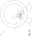
- the movement device 22 moves the applicator device 21 between the loading/unloading position (assumed in Figures 6-9 ), wherein the applicator device 21 is separated from, and external to, the pneumatic tyre 1, and the work position (illustrated in Figures 2 and 10 ) wherein the applicator device 21 is located inside the pneumatic tyre 1.
- the applicator roller 24 presses the strip 4 of sound-absorbing material 2 against the inner cavity of the pneumatic tyre 1, whilst the pneumatic tyre 1 is caused to rotate and, simultaneously, the recovery drum 26 is rotated synchronously with the pneumatic tyre 1, such as to wind the protective lining 7 around the recovery drum 26, step-by-step, as the protective lining 7 is separated from the strip 4 of sound-absorbing material 2.
- the applicator device 21, when it is in the work position within the pneumatic tyre 4, is configured to progressively separate the protective lining 7 from the strip 4 of sound-absorbing material 2, step-by-step, as the strip 4 of sound-absorbing material 2 is applied to the inner cavity of the pneumatic tyre 1.
- the presser roller 31 moves away from the strip 4 of sound-absorbing material 2 before commencing with the rotation of the pneumatic tyre 1; i.e., the actuator device 33 moves the presser roller 31 from the active position (illustrated in Figures 8, 9 and 10 ) to the passive position (illustrated in Figures 6 and 7 ) before commencing with the rotation of the pneumatic tyre 1.
- the application unit 3 described above has many advantages.
- the application unit 3 described above enables to fully automate the processing cycle, also as regards the separation of the initial part of the protective lining 7 from the sound-absorbing material 2; this result is obtained by virtue of the fact that the initial part of the protective lining 7 can be grasped by grasping the the residual portion 9 of the protective lining 7 which can be easily grasped, also in an automated manner (being of considerable size and substantially disconnected from the remaining part of the strip 4 of sound-absorbing material 2).
- the application unit 3 described above allows for the whole application cycle to be more efficient (i.e., faster and less expensive, especially by virtue of the possibility of complete automation) and also more effective (i.e., capable of ensuring high quality of application such to avert any damage to the sound-absorbing material 2).
- the application unit 3 described above ensures that, during the application within the inner cavity of the pneumatic tyre 1, the sound-absorbing material 2 does not undergo elongations or compressions which, after a few thousand kilometers of use of the pneumatic tyre 1, may lead to cracks within the same sound-absorbing material 2.
- the method described above for applying a sound-absorbing material 2 to an inner cavity of a pneumatic tyre 1 using a strip 4 of sound-absorbing material 2 provided on one side with an adhesive layer 6 covered with a protective lining 7 comprises the steps of:
Landscapes
- Engineering & Computer Science (AREA)
- Mechanical Engineering (AREA)
- Tires In General (AREA)
- Tyre Moulding (AREA)
Abstract
Description
- The present invention relates to a method and application unit for applying a sound-absorbing material in an inner cavity of a pneumatic tyre.
- As is known, a pneumatic tyre comprises a toroidal carcass, which has two annular beads and supports an annular tread. Between the carcass and the tread, a tread belt is interposed which is provided with a number of tread plies. Within the carcass, an innerliner is arranged which is airtight, constitutes an inner lining and has the function of retaining the air within the pneumatic tyre in order to maintain the inflation pressure of the pneumatic tyre itself over time.
- In recent years the development of pneumatic tyres has been directed towards pneumatic tyres that are internally (i.e. inside their cavity) provided with a sound-absorbing material (generally a sponge or a foam) for reducing the noise generated by a pneumatic tyre rolling on a road surface.
- The sound-absorbing material is applied to a pneumatic tyre that has already been vulcanized (inasmuch as the sound absorbing material would not be able to withstand, without being damaged, the combination of heat and pressure that is applied during the vulcanization process), and in particular it is glued or attached to the inner surface of the pneumatic tyre (comprising the innerliner) at the tread (i.e., corresponding to the area of the pneumatic tyre that comes into contact with the asphalt) and possibly also at part of the side walls.
- The sound-absorbing material is provided with an adhesive layer that is applied to the surface that is intended to contact the inner cavity of the pneumatic tyre and is initially covered (protected) with a removable protective lining ("liner") that serves the function of both protecting the adhesive layer, and the function of making it possible to wind the sound absorbing material into a coil without the sound-absorbing material sticking to itself.
- Typically, the process for the application of the sound-absorbing material inside the inner cavity of a pneumatic tyre provides for starting with a strip of sound-absorbing material (possibly wound into a coil) of a standard length that is more, i.e. longer than required; it is then necessary, initially, to cut the strip of sound-absorbing material in order to eliminate the excess part and thereby confer to the strip of sound-absorbing material the length required depending upon the inner circumference of the pneumatic tyre whereupon the strip of sound-absorbing material is to be glued; in other words, it is necessary, initially, to cut the strip of sound-absorbing material (or acoustic material) to size. After being cut to size, the strip of sound-absorbing material is wound onto itself such as to form a coil.
- In practice an operator loads the coil of the strip of sound-absorbing material that has been cut to size into an applicator device comprising an applicator roller that is configured in order to press, after the removal of the protective lining (which occurs a moment before pressing the sound-absorbing material against the inner surface), the sound-absorbing material against the inner surface of the pneumatic tyre; furthermore, the applicator device comprises a protective lining recovery drum whereupon the same protective lining is wound after being separated from the sound-absorbing material (i.e. after having completed its function). The applicator roller and the recovery drum are provided with actuating means that are suitable for bringing the same into rotation around the respective axis of rotation thereof, at appropriate and synchronous speeds, in such a way as to prevent the protective lining and/or the sound-absorbing material from tearing due to excessive tension or being too loose.
- When the operator loads the strip of sound-absorbing material into the applicator device, the operator has to manually separate, from the sound-absorbing material, an initial part of the protective lining, which has to then be inserted (again manually) into a slot in the recovery drum. During the application of sound-absorbing material, it is preferable to separate the protective lining from the sound-absorbing material just before the application thereof in such a way as to leave the adhesive exposed to air for as short a period of time as possible, in order to prevent foreign objects (debris, dust, dirt, insects... ) from accidentally adhering to the adhesive layer.
- In the meantime, the previously vulcanized pneumatic tyre is supported upon motorized rollers that cause it to rotate and that are provided with fixed side rails that prevent any lateral translation of the pneumatic tyre itself. In response to an operator command, an applicator device is inserted into the pneumatic tyre, carried by the motorized rollers, that presses a leading end of the strip of sound-absorbing material against the inner surface of the pneumatic tyre; the pneumatic tyre is then dragged into rotation by the motorized rollers in order to make it possible to apply the sound-absorbing material over the entire inner surface (i.e., making a full turn and thereby imparting an annular shape to the sound-absorbing material).
- The method described above for the application of sound-absorbing material within a pneumatic tyre inevitably requires the manual intervention of an operator in order to separate the initial part of the protective lining from the sound-absorbing material; moreover, this operation is particularly long and complicated, even for an experienced operator, and can result in damage to the adhesive layer.
- Furthermore, it is important that, during the application within the cavity, the sound-absorbing material does not undergo elongations or compressions which, after a few thousand kilometers of use of the pneumatic tyre, may lead to cracks within the sound-absorbing material itself.
- Improvements to the above processes have been presented by this same applicant in:
-
EP4143017 that discloses a system for applying a layer of sound-absorbing material to the inner surface of a cavity of a pneumatic tyre comprising an applicator device having an applicator roller for implementing the application of the layer of sound-absorbing material to the inner surface after the removal of a lining, a roller for winding the lining after the separation from the layer of sound-absorbing material and synchronization means implemented by means of a transmission member in order to make it possible to maintain substantially uniform the speed of the applicator roller and the winding roller
and in -
EP4171936 that discloses a method and an application unit for applying a sound-absorbing material to an inner cavity of a pneumatic tyre comprising the steps of: eliminating an excess end of a strip of sound-absorbing material; implementing by means of the strip a separation opening that starts from an opposite side of the protective lining and ends at the protective lining which remains intact, and separating the excess end from the remaining part of the strip of sound-absorbing material; and pulling the excess end in relation to the remaining part of the strip such as to separate the protective lining from the strip. - The object of the present invention is to provide a method and an application unit for applying a sound-absorbing material within an inner cavity of a pneumatic tyre, which method and application unit are an alternative to those known in the prior art and specificlly to the one disclosed in
EP4171936 and make it possible to render the entire application cycle even more efficient (i.e. quicker and less expensive) , more effective (i.e. capable of avoiding damage to the adhesive layer during the separation of the initial part of the protective lining from the sound-absorbing material) and even more sustainable since not requiring any cooling step. - According to the present invention a method and an application unit are provided for applying a sound-absorbing material inside an inner cavity of a pneumatic tyre, according to what set forth in the attached claims.
- The claims describe preferred embodiments of the present invention forming an integral part of the present description.
- The present invention will now be described with reference to the attached drawings, which show an exemplary, non-limiting embodiment, wherein:
-
Figure 1 is a schematic view of a pneumatic tyre provided with sound-absorbing material arranged inside an inner cavity of a pneumatic tyre; -
Figure 2 is a schematic view of an application unit for applying a sound-absorbing material inside the inner cvity of a tyre; -
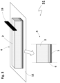
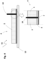
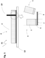
Figures 3 ,4 and5 are multiple views at different instants of operation of a separation station of the application unit ofFigure 2 , wherein an excess end is separated from a strip of sound-absorbing material; and -
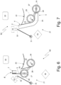
Figures 6-10 are multiple views at different instants of operation of a coupling station of the application unit ofFigure 2 wherein a strip of sound-absorbing material is applied to an inner cavity of a pneumatic tyre. - In
Figure 1 , thenumeral 1 denotes, in the entirety thereof, a pneumatic tyre that is mounted on a rim and that comprises a toroidal carcass having two annular beads and that supports an annular tread. Between the carcass and the tread, a tread belt is interposed which is provided with a number of tread plies. Within the carcass, an innerliner is arranged which is airtight, constitutes an inner lining and has the function of retaining the air within the pneumatic tyre in order to maintain the inflation pressure of the pneumatic tyre itself over time. Inside the inner cavity of thepneumatic tyre 1, i.e., in contact with the inner surface of thepneumatic tyre 1 comprising the innerliner, a loop (or annulus) ofsound absorbing material 2 is affixed (generally a sponge or a foam) to reduce the noise generated by the rolling of the pneumatic tyre upon the road surface. - The sound-absorbing
material 2 is applied to apneumatic tyre 1 that has already been vulcanized (inasmuch as thesound absorbing material 2 would not be able to withstand, without being damaged, the combination of heat and pressure that is applied during the vulcanization process), and in particular it is attached or glued to the inner surface of the pneumatic tyre 1 (comprising the innerliner) at the tread (i,e, corresponding to the area of the pneumatic tyre that contacts with the asphalt) and possibly (but not necessarily) also at part of the side walls. - In
Figure 2 , indicated in the entirety thereof with the number 3 is an application unit that is suitable for applying the sound-absorbingmaterial 2, having an annular form, to the inner cavity of thepneumatic tyre 1. The application unit 3 comprises a separation station S1, wherein an excess end 5 (illustrated inFigures 4 and5 ) is separated from astrip 4 of sound-absorbingmaterial 2 and a coupling station S2, wherein thestrip 4 of sound-absorbing material 2 (deprived of the excess end 5) is applied to the inner cavity of thepneumatic tyre 1. - In particular, the
strip 4 of sound-absorbingmaterial 2, initially, has a standard length that, depending upon the inner circumference of the inner cavity of thepneumatic tyre 1, is greater than the required length, and therefore, initially, it is necessary to cut it to size, removing from thestrip 4 of sound-absorbingmaterial 2 theexcess end 5 in such a way as to confer to thesame strip 4 of sound-absorbingmaterial 2 the required length (calculated as a function of the inner circumference of the pneumatic tyre 1). - As illustrated in
Figures 3 ,4 and5 , thestrip 4 of sound-absorbingmaterial 2 is provided on one side with anadhesive layer 6 that is intended to connect the sound-absorbingmaterial 2 to the inner surface of the pneumatic tyre and that is covered by a protective lining 7 (i.e., with a ribbon of plastic material that adheres in a removable manner to the adhesive layer 6). That is to say that theadhesive layer 6 is applied to the surface of the sound-absorbingmaterial 2 that is intended to come into contact with the inner cavity of thepneumatic tyre 1 and that is initially covered (protected) with the removableprotective lining 7 that serves both the function of protecting theadhesive layer 6 and the function of making it possible to wind thestrip 4 ofsound absorbing material 2 into a coil without thesound absorbing material 2 sticking to itself. - As previously stated, initially, in the separation station S1 the
strip 4 of sound-absorbingmaterial 2 is cut in such a way as to separate theexcess end 5 and to thereby confer the required length (in order to implement, without overlapping, a loop of sound-absorbingmaterial 2 within the pneumatic tyre 1) to thestrip 4 of sound-absorbingmaterial 2; normally thestrip 4 of sound-absorbingmaterial 2 initially has a length that is only slightly longer than necessary, and therefore the cutting to size of thestrip 4 of sound-absorbingmaterial 2 involves the waste of only a small piece of sound-absorbing material 2 (i.e., theexcess end 5 is small in size, generally ranging from a few centimeters to a few tens of centimeters). - As illustrated in
Figure 4 , by means of aheated instrument 19 thestrip 4 of sound-absorbingmaterial 2 is cut, starting from an opposite side of theprotective lining 7, leaving intact theprotective lining 7. Due to the fact that theinstrument 19 is heated, the cut or incision of the sound-absorbingmaterial 2 happens by way of thermal separation and not by way of mechanical separation, i.e. without mechanical friction. The heatedinstrument 19 can easily penetrate through the sound-absorbingmaterial 2 as well as through theadhesive layer 6, but cannot intact theprotective lining 7. In operation the heated instrument (19) has a temperature comprised in the range of 150 °C and 300 °C, preferably in the range of 240 °C and 280 °C, even more preferably around 260 °C. - The heated
instrument 19 can easily penetrate through the sound-absorbing material since due to the heat, the bonds of the cells of the sound-absorbing material (usually a sponge or foam) are easily broken. A too low temperaure would not lead to the same effect since the bonds would not break and a too high temperature would cause the material of the sound-absorbing material to burn causing a consequent non desired smoke generation. - The cut or incision operation separates the
excess end 5 from the remaining part of thestrip 4 of the sound-absorbingmaterial 2; in other words, the cut depth involves the entire depth of the sound-absorbingmaterial 2 and theadhesive layer 6, separating theexcess end 5 from the remaining part of thestrip 4 of sound-absorbingmaterial 2, without involving theprotective lining 7 which remains intact, constituting a residual connection between theexcess end 5 and the remaining part of thestrip 4 of sound-absorbingmaterial 2. - As illustrated in
Figure 5 , theexcess end 5 of thestrip 4 of sound-absorbingmaterial 2 is then eliminated such as to confer a required length to thesame strip 4 of sound-absorbingmaterial 2 and leaving intact aresidual portion 9 of theprotective lining 7. Theresidual portion 9 of theprotective lining 7 extends beyond the remaining part of thestrip 4 of sound-absorbingmaterial 2 from which theexcess end 5 has been removed from. - The heated
instrument 19 is preferably a blade, more preferably a heated blade. The blade can be of solid shape or have an U-shape. The U-shape of the blade facilitating the penetration into the sound-abosrbing material 2 during the cut (or incision) along the gauge of the sound-absorbingmaterial 2. - The
heated instrument 19 is preferably made of metal. - The heated
instrument 19 is preferbly heated electrically. - Preferably the
heated instrument 19 is blunt, i.e. it does not have sharp edges, to further preserve the integrity of theprotective lining 7. - As illustrated in
Figure 2 , once thestrip 4 of sound-absorbingmaterial 2 has completed the processing cycle thereof in the separation station S1 (i.e., when the cut has been completed which separates theexcess end 5 from the remaining part of thestrip 4 of sound-absorbingmaterial 2, leaving intact theprotective lining 7 and theexcess portion 5 has been eliminated), thestrip 4 of sound-absorbingmaterial 2 is wound on itself such as to form a coil (which terminates externally with theresidual portion 9 of the protective lining 7) and is then transferred (in more or less an automated manner) to the coupling station S2. - The coupling station S2 comprises a support device that is suitable for supporting and bringing into rotation, around a central axis thereof, the
pneumatic tyre 1. In particular, thesupport device 20 comprises motorized rollers whereupon thepneumatic tyre 1 itself rests and side rails (not illustrated) that contain thepneumatic tyre 1, preventing thepneumatic tyre 1 from performing any form of lateral translation during the rotational movement thereof. - The coupling station S2 comprises an
applicator device 21 that is suitable for applying thestrip 4 of sound-absorbingmaterial 2 to the inner surface of thepneumatic tyre 1, progressively removing theprotective lining 7. That is to say, theapplicator device 21 progressively separates theprotective lining 7 from thestrip 4 of sound-absorbingmaterial 2 as thestrip 4 of sound-absorbingmaterial 2 is applied to the inner cavity of thepneumatic tyre 1; in particular, theapplicator device 21 initially pulls theresidual portion 9 of theprotective lining 7 in relation to the remaining part of thestrip 4 of sound-absorbingmaterial 2 such as to separate theprotective lining 7 from thestrip 4 of sound-absorbingmaterial 2, i.e. theapplicator device 21 uses theresidual portion 9 of theprotective lining 7 as a gripping point in order to begin to separate theprotective lining 7 from thestrip 4 of sound-absorbingmaterial 2. - The coupling station S2 comprises a
movement device 22 that supports theapplicator device 21 and that is suitable for moving theapplicator device 21 between a loading/unloading position wherein theapplicator device 21 is separated from the pneumatic tyre 1 (that is external to the pneumatic tyre 1) and a work position (illustrated inFigure 2 ) wherein theapplicator device 21 is located within thepneumatic tyre 1. In the loading/unloading position, anew strip 4 of sound-absorbingmaterial 2, wound into a coil, is loaded into theapplicator device 21 whilst only the previously appliedprotective lining 7 of astrip 4 of sound-absorbingmaterial 2 is unloaded (removed) from theapplicator device 21. Conversely, in the work position (illustrated inFigure 2 ) anew strip 4 of sound-absorbingmaterial 2, inserted into theapplicator device 21, is applied to the inner cavity of thepneumatic tyre 1. - According to what illustrated in
Figures 6-10 , theapplicator device 21 comprises ahousing 23 that is suitable for containing thestrip 4 of sound-absorbingmaterial 2 wound into a coil, anapplicator roller 24 which, being mounted rotating around an axis ofrotation 25, is suitable for pressing thestrip 4 of sound-absorbingmaterial 2 against the inner surface of thepneumatic tyre 1 in order to adhere thestrip 4 of sound-absorbingmaterial 2 to the inner surface of thepneumatic tyre 1, and arecovery drum 26 that is mounted rotating around anaxis 27 of rotation parallel to theaxis 25 of rotation, and that is suitable for winding theprotective lining 7, step-by-step, such that theprotective lining 7 is separated from thestrip 4 of sound-absorbingmaterial 2. In particular, thehousing 23 is arranged above theapplicator roller 24 and above therecovery drum 26. In other words, theapplicator device 21 comprises anapplicator roller 24 that is configured to press the sound-absorbingmaterial 2 against the inner surface of thepneumatic tyre 1, after the removal of theprotective lining 7, which occurs a moment before pressing the sound-absorbingmaterial 2 against the inner surface of thepneumatic tyre 1; furthermore, theapplicator device 21 comprises a protectivelining recovery drum 26, whereupon the sameprotective lining 7 is wound after being separated from the sound-absorbingmaterial 2, i.e., after having completed its function. - During the application of the sound-absorbing
material 2, it is preferable to separate theprotective lining 7 from the sound-absorbingmaterial 2, just before the application thereof, in such a way as to leave theadhesive layer 6 exposed to air for as short a period of time as possible, in order to prevent foreign objects (debris, dust, dirt, insects... ) from accidentally adhering to theadhesive layer 6. - The
applicator roller 24 and therecovery drum 26 are provided with actuating means that are suitable for bringing them into rotation around therespective axis protective lining 7 and/or the sound-absorbingmaterial 2 from tearing due to excessive tension or being too loose. - In one alternative embodiment the
applicator roller 24 and therecovery drum 26 are provided with actuating means that are suitable for bringing them into rotation around therespective axis protective lining 7 and/or the sound-absorbingmaterial 2 can be adjusted. - The
recovery drum 26 is provided with a motorized grip member 28 (for example a gripper provided with two opposing jaws) that is suitable for grasping theresidual portion 9 of theprotective lining 7 of thestrip 4 of sound-absorbingmaterial 2 that is wound into a coil and located in thehousing 23; i.e., therecovery drum 26 supports themotorized grip member 28 that is suitable for grasping theresidual portion 9 of theprotective lining 7 of thestrip 4 of sound-absorbingmaterial 2. - The
recovery drum 26 is mounted movable in theapplicator device 21 in order to move itself to different positions (illustrated inFigures 6-10 ) along a circular trajectory (i.e., along an arc of circumference); i.e., therecovery drum 26, other than being mounted rotating around thecentral axis 27 of rotation in order to rotate upon itself, it is pivotally mounted in order to rotate around afurther axis 29 of rotation that is parallel and eccentric (i.e., non-coaxial) in relation to theaxis applicator roller 24 and the recovery drum 26). In particular, anactuator device 30 is provided that moves, as will be explained below, therecovery drum 26, by rotating therecovery drum 26 about theaxis 29 of rotation (i.e., causing therecovery drum 26 to complete a circular path). - The
applicator device 21 comprises apresser roller 31 that is suitable for pressing thestrip 4 of sound-absorbingmaterial 2 against theapplicator roller 24 and that is mounted idling at one end of an arm that is hinged such as to rotate around anaxis 32 of rotation (parallel to theaxis actuator device 33. In rotating around theaxis 32 of rotation, thepresser roller 31 is movable between a passive position (illustrated inFigures 6 and 7 ) wherein thepresser roller 31 is at a distance from theapplicator roller 24 and from thestrip 4 of sound-absorbingmaterial 2, and an active position (illustrated inFigures 8, 9 and10 ) wherein thepresser roller 31 presses thestrip 4 of sound-absorbingmaterial 2 against theapplicator roller 24. - Whilst the
applicator device 21 is located in the loading/unloading position (i.e., externally to the pneumatic tyre 1), thestrip 4 of sound-absorbingmaterial 2 is inserted, coiled, into thehousing 23 of theapplicator device 21, arranging the theresidual portion 9 of theprotective lining 7 outside thehousing 23 and facing downwards. Subsequently, themotorized grip member 28 of therecovery drum 26 grasps the theresidual portion 9 of theprotective lining 7; during this step, therecovery drum 26 is arranged at an initial position (illustrated inFigure 6 ) wherein therecovery drum 26 is arranged to the left of the applicator drum 24 (i.e., from a first side of the applicator drum 24) and is facing an outlet of thehousing 23. - Subsequently, the
actuator device 30 moves therecovery drum 26, which is holding theresidual portion 9 of theprotective lining 7, from the initial position (illustrated inFigure 6 ) to an intermediate position (illustrated inFigure 7 ) wherein therecovery drum 26 is arranged to the right of the applicator drum 24 (i.e., from a second side of theapplicator drum 24 opposite the first side) such as to partially wind thestrip 4 of sound-absorbingmaterial 2 around theapplicator roller 24. In other words, theactuator device 30 moves therecovery drum 26, which is holding the theresidual portion 9 of theprotective lining 7, from the first side of theapplicator roller 24 to the second side of theapplicator roller 24 opposite the first side, such as to partially wind thestrip 4 of sound-absorbingmaterial 2 around theapplicator roller 24. - Subsequently and as illustrated in
Figure 8 , theactuator device 33 moves thepresser roller 31 from the passive position (illustrated inFigure 7 ) to the active position (illustrated inFigure 8 ) such as to press thestrip 4 of sound-absorbingmaterial 2 against theapplicator roller 24. - Subsequently and as illustrated in
Figure 9 , theactuator device 30 moves therecovery drum 26, which is holding the theresidual portion 9 of theprotective lining 7, from the intermediate position (illustrated inFigures 7 and8 ) to a final position (illustrated inFigure 9 ) wherein therecovery drum 26 is arranged to the left of the applicator drum 24 (i.e., from the first side of the applicator drum 24) such as to separate part of theprotective lining 7 from thestrip 4 of sound-absorbingmaterial 2. In other words, theactuator device 30 moves therecovery drum 26, which is holding the theresidual portion 9 of theprotective lining 7, from the second side of theapplicator roller 24 to the first side of theapplicator roller 24, such as to separate part of theprotective lining 7 from thestrip 4 of sound-absorbingmaterial 2. When therecovery drum 26 is moved from the intermediate position (illustrated inFigures 7 and8 ), which is located at the second side of theapplicator roller 24, to the final position (illustrated inFigures 9 and10 ), which is located at the first side of theapplicator roller 24, theprotective lining 7 is partially wound around therecovery drum 26. - Thus, the
applicator device 21 is suitable for pulling the theresidual portion 9 of theprotective lining 7 in relation to the remaining part of thestrip 4 of sound-absorbingmaterial 2 such as to separate theprotective lining 7 from thestrip 4 of sound-absorbingmaterial 2. - In particular, the final position (illustrated in
Figure 9 ) of therecovery drum 26 is different than the initial position (illustrated inFigure 7 ) of therecovery drum 26, i.e., when therecovery drum 26 is moved from the second side of theapplicator roller 24 to the first side of theapplicator roller 24, then it is arranged in the final position (illustrated inFigure 9 ), which is different in relation to the initial position (illustrated inFigure 6 ) that is assumed in order to grasp the theresidual portion 9 of the protective lining 7 (i.e. to grasp the initial part of the protective lining 7). - It should be noted that the
recovery drum 26 is moved from the intermediate position (illustrated inFigures 7 and8 ), which is located at the second side of theapplicator roller 24, to the final position (illustrated inFigures 9 and10 ), which is located at the first side of theapplicator roller 24, before inserting the applicator device 21 (comprising theapplicator roller 24 and the recovery drum 26) into thepneumatic tyre 1. - At this point and as illustrated in
Figure 10 , themovement device 22 moves theapplicator device 21 between the loading/unloading position (assumed inFigures 6-9 ), wherein theapplicator device 21 is separated from, and external to, thepneumatic tyre 1, and the work position (illustrated inFigures 2 and10 ) wherein theapplicator device 21 is located inside thepneumatic tyre 1. In the work position (illustrated inFigures 2 and10 ), theapplicator roller 24 presses thestrip 4 of sound-absorbingmaterial 2 against the inner cavity of thepneumatic tyre 1, whilst thepneumatic tyre 1 is caused to rotate and, simultaneously, therecovery drum 26 is rotated synchronously with thepneumatic tyre 1, such as to wind theprotective lining 7 around therecovery drum 26, step-by-step, as theprotective lining 7 is separated from thestrip 4 of sound-absorbingmaterial 2. - In other words, the
applicator device 21, when it is in the work position within thepneumatic tyre 4, is configured to progressively separate theprotective lining 7 from thestrip 4 of sound-absorbingmaterial 2, step-by-step, as thestrip 4 of sound-absorbingmaterial 2 is applied to the inner cavity of thepneumatic tyre 1. - According to a preferred embodiment, the
presser roller 31 moves away from thestrip 4 of sound-absorbingmaterial 2 before commencing with the rotation of thepneumatic tyre 1; i.e., theactuator device 33 moves thepresser roller 31 from the active position (illustrated inFigures 8, 9 and10 ) to the passive position (illustrated inFigures 6 and 7 ) before commencing with the rotation of thepneumatic tyre 1. - The embodiments described herein may be combined without departing from the scope of protection of the present invention.
- The application unit 3 described above has many advantages.
- In the first place, the application unit 3 described above enables to fully automate the processing cycle, also as regards the separation of the initial part of the
protective lining 7 from the sound-absorbingmaterial 2; this result is obtained by virtue of the fact that the initial part of theprotective lining 7 can be grasped by grasping the theresidual portion 9 of theprotective lining 7 which can be easily grasped, also in an automated manner (being of considerable size and substantially disconnected from the remaining part of thestrip 4 of sound-absorbing material 2). - Furthermore, the application unit 3 described above allows for the whole application cycle to be more efficient (i.e., faster and less expensive, especially by virtue of the possibility of complete automation) and also more effective (i.e., capable of ensuring high quality of application such to avert any damage to the sound-absorbing material 2).
- In particular, the application unit 3 described above ensures that, during the application within the inner cavity of the
pneumatic tyre 1, the sound-absorbingmaterial 2 does not undergo elongations or compressions which, after a few thousand kilometers of use of thepneumatic tyre 1, may lead to cracks within the same sound-absorbingmaterial 2. - The method described above for applying a sound-absorbing
material 2 to an inner cavity of apneumatic tyre 1 using astrip 4 of sound-absorbingmaterial 2 provided on one side with anadhesive layer 6 covered with aprotective lining 7 comprises the steps of: - cutting, starting from an opposite side of the
protective lining 7, thestrip 4 of sound-absorbingmaterial 2 and leaving intact theprotective lining 7; - separating an
excess end 5 from the remaining part of thestrip 4 of sound-absorbingmaterial 2; - eliminating the
excess end 5 of thestrip 4 of sound-absorbingmaterial 2 such as to confer a required length to thesame strip 4 of sound-absorbingmaterial 2 and leaving intact aresidual portion 9 of theprotective lining 7; - progressively separating the
protective lining 7 from thestrip 4 of sound-absorbingmaterial 2, step-by-step, as thestrip 4 of sound-absorbingmaterial 2 is applied to the inner cavity of thepneumatic tyre 1; - wherein the cutting step is carried out by means of a
heated instrument 19. -
- 1 pneumatic tyre
- 2 sound-absorbing material
- 3 application unit
- 4 strip
- 5 excess end
- 6 adhesive layer
- 7 protective lining
- 8 separation opening
- 9 residual portion of the protective lining
- 12 support plane
- 19 heated instrument
- 20 motorized rollers
- 21 applicator device
- 22 movement device
- 23 housing
- 24 applicator roller
- 25 axis of rotation
- 26 recovery drum
- 27 axis of rotation
- 27 presser member
- 29 axis of rotation
- 30 actuator device
- 31 presser roller
- 32 axis of rotation
- 33 actuator device
- S1 separation station
- S2 coupling station
Claims (13)
- Method for applying a sound-absorbing material (2) to an inner cavity of a pneumatic tyre (1) using a strip (4) of sound-absorbing material (2) provided on one side with an adhesive layer (6) covered with a protective lining (7);
the method comprising the steps of:cutting, starting from an opposite side of the protective lining (7), the strip (4) of sound-absorbing material (2) and leaving intact the protective lining (7);separating an excess end (5) from the remaining part of the strip (4) of sound-absorbing material (2);eliminating the excess end (5) of the strip (4) of sound-absorbing material (2) such as to confer a required length to the same strip (4) of sound-absorbing material (2) and leaving intact a residual portion (9) of the protective lining (7);progressively separating the protective lining (7) from the strip (4) of sound-absorbing material (2), step-by-step, as the strip (4) of sound-absorbing material (2) is applied to the inner cavity of the pneumatic tyre (1);the method being characterized in thatit further comprises the step of utilizing a heated instrument (19) for cuttng the strip (4) of sound-absorbing material (2). - Method according to claim 1, wherein the step of eliminating the excess end (5) of the strip (4) of sound-absorbing material (2) further comprises the step of eliminating the adhesive layer (6) corresponding and adhered to the excess end (5) .
- Method according to any of the preceding claims, wherein the heated instrument (19) is blunt.
- Method according to any of the preceding claims wherein the heated instrument (19) is a blade.
- Method according to any of the preceding claims wherein when in operation the heated instrument (19) has a temperature comprised in the range of 150 °C and 300 °C, preferably comprised in the range of 240 °C and 280 °C and even more preferably a temperature of about 260 °C.
- Method according to any of the preceding claims, wherein the heated instrument (19) is U-shaped.
- Method according to any of the preceding claims and comprising the further steps of:grasping the residual portion (9) of the protective lining (7); by means of a grip member (28) that is integral to a recovery drum (26) and whilst the recovery drum (26) is at a first side of an applicator roller (24);moving the recovery drum (26), which is holding the residual portion (9) of the protective lining (7), from the first side of the applicator roller (24) to the second side of the applicator roller (24), opposite the first side, such as to partially wind the strip (4) of sound-absorbing material (2) around the applicator roller (24);pressing the strip (4) of sound-absorbing material (2) against the applicator roller (24) by means of a presser roller (31); andmoving the recovery drum (26), which is holding the residual portion (9) of the protective lining (7), from the second side of the applicator roller (24) to the first side of the applicator roller (24), such as to separate part of the protective lining (7) from the strip (4) of sound-absorbing material (2).
- Method according to claim 7 and comprising the further steps of:pressing, by means of the applicator roller (24), the strip (4) of sound-absorbing material (2) against the inner cavity of the pneumatic tyre (1) whilst the pneumatic tyre (1) is caused to rotate; androtating the recovery drum (26) synchronously with the pneumatic tyre (1) in order to wind the protective lining (7) around the recovery drum (26), step-by-step, as the protective lining (7) is separated from the strip (4) of sound-absorbing material (2).
- Application unit (3) for applying a sound-absorbing material (2) in an inner cavity of a pneumatic tyre (1) using a strip (4) of sound-absorbing material (2) provided on one side with an adhesive layer (6) covered with a protective lining (7); the application unit (3) comprising:a separation station (S1) that is suitable for eliminating an excess end (5) of the strip (4) of sound-absorbing material (2) such as to confer a required length to the same strip (4) of sound-absorbing material (2); andan applicator device (21) that is configured in order to progressively separate the protective lining (7) from the strip (4) of sound-absorbing material (2), step-by-step, as the strip (4) of sound-absorbing material (2) is applied to the inner cavity of the pneumatic tyre (1);the application unit (3) is characterized in that:the separation station (S1) is configured such as to cut by means of a heated instrument (19), starting from an opposite side of the protective lining (7), the strip (4) of sound-absorbing material (2) and leave intact the protective lining (7);separate an excess end (5) from the remaining part of the strip (4) of sound-absorbing material (2);eliminate the excess end (5) of the strip (4) of sound-absorbing material (2) such as to confer a required length to the same strip (4) of sound-absorbing material (2) and leave intact a residual portion (9) of the protective lining (7);
- Application unit (3) according to claim 9, wherein the heated instrument (19) is blunt.
- Application unit (3) according to claims 9-10, wherein the heated instrument (19) is a blade.
- Application unit (3) according to claims 9-11, wherein when in operation the heated instrument (19) has a temperature comprised in the range of 150 °C and 300 °C, preferably comprised in the range of 240 °C and 280 °C and even more preferably about 260 °C.
- Application unit (3) according to claims 9-12, wherein the heated instrument (19) is U-shaped.
Priority Applications (4)
| Application Number | Priority Date | Filing Date | Title |
|---|---|---|---|
| ES23205070T ES3069717T3 (en) | 2023-10-22 | 2023-10-22 | Method and application unit for applying a sound-absorbing material in an inner cavity of a pneumatic tyre |
| EP23205070.8A EP4541569B1 (en) | 2023-10-22 | 2023-10-22 | Method and application unit for applying a sound-absorbing material in an inner cavity of a pneumatic tyre |
| PCT/IB2024/060370 WO2025088487A1 (en) | 2023-10-22 | 2024-10-22 | Method and application unit for applying a sound-absorbing material in an inner cavity of a pneumatic tyre |
| CN202480066621.1A CN122055261A (en) | 2023-10-22 | 2024-10-22 | Method and application unit for applying sound-absorbing material in an inner cavity of a pneumatic tire |
Applications Claiming Priority (1)
| Application Number | Priority Date | Filing Date | Title |
|---|---|---|---|
| EP23205070.8A EP4541569B1 (en) | 2023-10-22 | 2023-10-22 | Method and application unit for applying a sound-absorbing material in an inner cavity of a pneumatic tyre |
Publications (2)
| Publication Number | Publication Date |
|---|---|
| EP4541569A1 true EP4541569A1 (en) | 2025-04-23 |
| EP4541569B1 EP4541569B1 (en) | 2026-03-04 |
Family
ID=88511118
Family Applications (1)
| Application Number | Title | Priority Date | Filing Date |
|---|---|---|---|
| EP23205070.8A Active EP4541569B1 (en) | 2023-10-22 | 2023-10-22 | Method and application unit for applying a sound-absorbing material in an inner cavity of a pneumatic tyre |
Country Status (4)
| Country | Link |
|---|---|
| EP (1) | EP4541569B1 (en) |
| CN (1) | CN122055261A (en) |
| ES (1) | ES3069717T3 (en) |
| WO (1) | WO2025088487A1 (en) |
Citations (8)
| Publication number | Priority date | Publication date | Assignee | Title |
|---|---|---|---|---|
| EP0714740A1 (en) * | 1994-10-28 | 1996-06-05 | The Goodyear Tire & Rubber Company | System for cutting a strip of elastomeric material such as a tire tread |
| EP1123197A1 (en) * | 1998-10-20 | 2001-08-16 | The Goodyear Tire & Rubber Company | Method and apparatus for cutting elastomeric materials |
| JP2007168243A (en) * | 2005-12-21 | 2007-07-05 | Sumitomo Rubber Ind Ltd | Method for pasting strip sponge material to inner surface of tread and pasting device |
| WO2016067192A1 (en) * | 2014-10-29 | 2016-05-06 | Pirelli Tyre S.P.A. | Process and apparatus for automatically applying a noise reducing element to a tyre for vehicle wheels |
| EP3544798A1 (en) * | 2016-11-22 | 2019-10-02 | Pirelli Tyre S.p.A. | Process and apparatus for applying noise-reducing elements to a tyre for vehicle wheels |
| WO2022002799A1 (en) * | 2020-06-30 | 2022-01-06 | Bridgestone Europe Nv/Sa | Method and application unit for applying a sound-absorbing material in an inner cavity of a pneumatic tyre |
| EP4143017A1 (en) | 2020-04-30 | 2023-03-08 | Bridgestone Europe NV/SA | Method and system for applying a layer of soundabsorbing material to the surface of an inner cavity of a pneumatic tyre |
| EP4171936A1 (en) | 2020-06-30 | 2023-05-03 | Bridgestone Europe NV/SA | Method and application unit for applying a sound-absorbing material in an inner cavity of a pneumatic tyre |
-
2023
- 2023-10-22 EP EP23205070.8A patent/EP4541569B1/en active Active
- 2023-10-22 ES ES23205070T patent/ES3069717T3/en active Active
-
2024
- 2024-10-22 WO PCT/IB2024/060370 patent/WO2025088487A1/en not_active Ceased
- 2024-10-22 CN CN202480066621.1A patent/CN122055261A/en active Pending
Patent Citations (8)
| Publication number | Priority date | Publication date | Assignee | Title |
|---|---|---|---|---|
| EP0714740A1 (en) * | 1994-10-28 | 1996-06-05 | The Goodyear Tire & Rubber Company | System for cutting a strip of elastomeric material such as a tire tread |
| EP1123197A1 (en) * | 1998-10-20 | 2001-08-16 | The Goodyear Tire & Rubber Company | Method and apparatus for cutting elastomeric materials |
| JP2007168243A (en) * | 2005-12-21 | 2007-07-05 | Sumitomo Rubber Ind Ltd | Method for pasting strip sponge material to inner surface of tread and pasting device |
| WO2016067192A1 (en) * | 2014-10-29 | 2016-05-06 | Pirelli Tyre S.P.A. | Process and apparatus for automatically applying a noise reducing element to a tyre for vehicle wheels |
| EP3544798A1 (en) * | 2016-11-22 | 2019-10-02 | Pirelli Tyre S.p.A. | Process and apparatus for applying noise-reducing elements to a tyre for vehicle wheels |
| EP4143017A1 (en) | 2020-04-30 | 2023-03-08 | Bridgestone Europe NV/SA | Method and system for applying a layer of soundabsorbing material to the surface of an inner cavity of a pneumatic tyre |
| WO2022002799A1 (en) * | 2020-06-30 | 2022-01-06 | Bridgestone Europe Nv/Sa | Method and application unit for applying a sound-absorbing material in an inner cavity of a pneumatic tyre |
| EP4171936A1 (en) | 2020-06-30 | 2023-05-03 | Bridgestone Europe NV/SA | Method and application unit for applying a sound-absorbing material in an inner cavity of a pneumatic tyre |
Also Published As
| Publication number | Publication date |
|---|---|
| WO2025088487A1 (en) | 2025-05-01 |
| CN122055261A (en) | 2026-05-15 |
| ES3069717T3 (en) | 2026-06-10 |
| EP4541569B1 (en) | 2026-03-04 |
Similar Documents
| Publication | Publication Date | Title |
|---|---|---|
| US20250353267A1 (en) | Method and application unit for applying a sound-absorbing material in an inner cavity of a pneumatic tire | |
| JPH0255345B2 (en) | ||
| WO2016067192A1 (en) | Process and apparatus for automatically applying a noise reducing element to a tyre for vehicle wheels | |
| KR101926647B1 (en) | A deposition head for depositing an impregnated fiber tape, and a device for placing such a tape | |
| EP4143017B1 (en) | Method and system for applying a layer of soundabsorbing material to the surface of an inner cavity of a pneumatic tyre | |
| EP4541569B1 (en) | Method and application unit for applying a sound-absorbing material in an inner cavity of a pneumatic tyre | |
| EP4171936B1 (en) | Method and application unit for applying a sound-absorbing material in an inner cavity of a pneumatic tyre | |
| JPS59207227A (en) | Method and apparatus for winding band-shaped member about tire molding drum | |
| JPH0137261B2 (en) | ||
| JP2534514B2 (en) | Temporary pressure bonding method in tire molding process | |
| JPS6149835A (en) | Reclaimed tire | |
| EP1831003B1 (en) | Machines and methods for manufacturing a component of a car tyre | |
| JP4590807B2 (en) | Method and apparatus for laminating sheet material | |
| JPH03261544A (en) | Method and apparatus for automatic feeding and cutting of film material in tire molding process | |
| WO2001017761A1 (en) | Apparatus for stitching and seaming elastomeric fillers to tire beads | |
| EA042451B1 (en) | METHOD AND SYSTEM FOR APPLICATION OF LAYER OF SOUND-ABSORBING MATERIAL ON SURFACE OF INTERIOR CAVITY OF PNEUMATIC TIRE | |
| JPH0137262B2 (en) | ||
| JPH04367413A (en) | Method and device for roll packaging | |
| JPS6249853B2 (en) | ||
| JP2005271411A (en) | Method and apparatus for winding strip-like material |
Legal Events
| Date | Code | Title | Description |
|---|---|---|---|
| PUAI | Public reference made under article 153(3) epc to a published international application that has entered the european phase |
Free format text: ORIGINAL CODE: 0009012 |
|
| STAA | Information on the status of an ep patent application or granted ep patent |
Free format text: STATUS: THE APPLICATION HAS BEEN PUBLISHED |
|
| AK | Designated contracting states |
Kind code of ref document: A1 Designated state(s): AL AT BE BG CH CY CZ DE DK EE ES FI FR GB GR HR HU IE IS IT LI LT LU LV MC ME MK MT NL NO PL PT RO RS SE SI SK SM TR |
|
| STAA | Information on the status of an ep patent application or granted ep patent |
Free format text: STATUS: REQUEST FOR EXAMINATION WAS MADE |
|
| 17P | Request for examination filed |
Effective date: 20250521 |
|
| GRAP | Despatch of communication of intention to grant a patent |
Free format text: ORIGINAL CODE: EPIDOSNIGR1 |
|
| STAA | Information on the status of an ep patent application or granted ep patent |
Free format text: STATUS: GRANT OF PATENT IS INTENDED |
|
| INTG | Intention to grant announced |
Effective date: 20250930 |
|
| GRAS | Grant fee paid |
Free format text: ORIGINAL CODE: EPIDOSNIGR3 |
|
| GRAA | (expected) grant |
Free format text: ORIGINAL CODE: 0009210 |
|
| STAA | Information on the status of an ep patent application or granted ep patent |
Free format text: STATUS: THE PATENT HAS BEEN GRANTED |
|
| AK | Designated contracting states |
Kind code of ref document: B1 Designated state(s): AL AT BE BG CH CY CZ DE DK EE ES FI FR GB GR HR HU IE IS IT LI LT LU LV MC ME MK MT NL NO PL PT RO RS SE SI SK SM TR |
|
| P01 | Opt-out of the competence of the unified patent court (upc) registered |
Free format text: CASE NUMBER: UPC_APP_0002367_4541569/2026 Effective date: 20260122 |
|
| REG | Reference to a national code |
Ref country code: CH Ref legal event code: F10 Free format text: ST27 STATUS EVENT CODE: U-0-0-F10-F00 (AS PROVIDED BY THE NATIONAL OFFICE) Effective date: 20260304 Ref country code: GB Ref legal event code: FG4D |
|
| REG | Reference to a national code |
Ref country code: IE Ref legal event code: FG4D |
|
| REG | Reference to a national code |
Ref country code: DE Ref legal event code: R096 Ref document number: 602023012927 Country of ref document: DE |
|
| REG | Reference to a national code |
Ref country code: ES Ref legal event code: FG2A Ref document number: 3069717 Country of ref document: ES Kind code of ref document: T3 Effective date: 20260610 |
|
| PG25 | Lapsed in a contracting state [announced via postgrant information from national office to epo] |
Ref country code: RS Free format text: LAPSE BECAUSE OF FAILURE TO SUBMIT A TRANSLATION OF THE DESCRIPTION OR TO PAY THE FEE WITHIN THE PRESCRIBED TIME-LIMIT Effective date: 20260604 |
|
| REG | Reference to a national code |
Ref country code: NL Ref legal event code: MP Effective date: 20260304 |
|
| PG25 | Lapsed in a contracting state [announced via postgrant information from national office to epo] |
Ref country code: PL Free format text: LAPSE BECAUSE OF FAILURE TO SUBMIT A TRANSLATION OF THE DESCRIPTION OR TO PAY THE FEE WITHIN THE PRESCRIBED TIME-LIMIT Effective date: 20260304 |
|
| PG25 | Lapsed in a contracting state [announced via postgrant information from national office to epo] |
Ref country code: GR Free format text: LAPSE BECAUSE OF FAILURE TO SUBMIT A TRANSLATION OF THE DESCRIPTION OR TO PAY THE FEE WITHIN THE PRESCRIBED TIME-LIMIT Effective date: 20260605 |
|
| REG | Reference to a national code |
Ref country code: LT Ref legal event code: MG9D |
|
| PG25 | Lapsed in a contracting state [announced via postgrant information from national office to epo] |
Ref country code: LT Free format text: LAPSE BECAUSE OF FAILURE TO SUBMIT A TRANSLATION OF THE DESCRIPTION OR TO PAY THE FEE WITHIN THE PRESCRIBED TIME-LIMIT Effective date: 20260304 |
|
| PG25 | Lapsed in a contracting state [announced via postgrant information from national office to epo] |
Ref country code: NO Free format text: LAPSE BECAUSE OF FAILURE TO SUBMIT A TRANSLATION OF THE DESCRIPTION OR TO PAY THE FEE WITHIN THE PRESCRIBED TIME-LIMIT Effective date: 20260604 |
|
| PG25 | Lapsed in a contracting state [announced via postgrant information from national office to epo] |
Ref country code: SE Free format text: LAPSE BECAUSE OF FAILURE TO SUBMIT A TRANSLATION OF THE DESCRIPTION OR TO PAY THE FEE WITHIN THE PRESCRIBED TIME-LIMIT Effective date: 20260304 Ref country code: FI Free format text: LAPSE BECAUSE OF FAILURE TO SUBMIT A TRANSLATION OF THE DESCRIPTION OR TO PAY THE FEE WITHIN THE PRESCRIBED TIME-LIMIT Effective date: 20260304 |
|
| PG25 | Lapsed in a contracting state [announced via postgrant information from national office to epo] |
Ref country code: HR Free format text: LAPSE BECAUSE OF FAILURE TO SUBMIT A TRANSLATION OF THE DESCRIPTION OR TO PAY THE FEE WITHIN THE PRESCRIBED TIME-LIMIT Effective date: 20260304 |
|
| PG25 | Lapsed in a contracting state [announced via postgrant information from national office to epo] |
Ref country code: LV Free format text: LAPSE BECAUSE OF FAILURE TO SUBMIT A TRANSLATION OF THE DESCRIPTION OR TO PAY THE FEE WITHIN THE PRESCRIBED TIME-LIMIT Effective date: 20260304 |
|
| PG25 | Lapsed in a contracting state [announced via postgrant information from national office to epo] |
Ref country code: BG Free format text: LAPSE BECAUSE OF FAILURE TO SUBMIT A TRANSLATION OF THE DESCRIPTION OR TO PAY THE FEE WITHIN THE PRESCRIBED TIME-LIMIT Effective date: 20260304 |
|
| REG | Reference to a national code |
Ref country code: HU Ref legal event code: AG4A Ref document number: E076003 Country of ref document: HU |