EP4541564A1 - Composite backing layer peel starter - Google Patents
Composite backing layer peel starter Download PDFInfo
- Publication number
- EP4541564A1 EP4541564A1 EP24190527.2A EP24190527A EP4541564A1 EP 4541564 A1 EP4541564 A1 EP 4541564A1 EP 24190527 A EP24190527 A EP 24190527A EP 4541564 A1 EP4541564 A1 EP 4541564A1
- Authority
- EP
- European Patent Office
- Prior art keywords
- backing layer
- composite
- contact surface
- striker
- starter
- Prior art date
- Legal status (The legal status is an assumption and is not a legal conclusion. Google has not performed a legal analysis and makes no representation as to the accuracy of the status listed.)
- Pending
Links
Images




Classifications
-
- B—PERFORMING OPERATIONS; TRANSPORTING
- B32—LAYERED PRODUCTS
- B32B—LAYERED PRODUCTS, i.e. PRODUCTS BUILT-UP OF STRATA OF FLAT OR NON-FLAT, e.g. CELLULAR OR HONEYCOMB, FORM
- B32B7/00—Layered products characterised by the relation between layers; Layered products characterised by the relative orientation of features between layers, or by the relative values of a measurable parameter between layers, i.e. products comprising layers having different physical, chemical or physicochemical properties; Layered products characterised by the interconnection of layers
- B32B7/04—Interconnection of layers
- B32B7/06—Interconnection of layers permitting easy separation
-
- B—PERFORMING OPERATIONS; TRANSPORTING
- B32—LAYERED PRODUCTS
- B32B—LAYERED PRODUCTS, i.e. PRODUCTS BUILT-UP OF STRATA OF FLAT OR NON-FLAT, e.g. CELLULAR OR HONEYCOMB, FORM
- B32B43/00—Operations specially adapted for layered products and not otherwise provided for, e.g. repairing; Apparatus therefor
- B32B43/006—Delaminating
-
- B—PERFORMING OPERATIONS; TRANSPORTING
- B29—WORKING OF PLASTICS; WORKING OF SUBSTANCES IN A PLASTIC STATE IN GENERAL
- B29C—SHAPING OR JOINING OF PLASTICS; SHAPING OF MATERIAL IN A PLASTIC STATE, NOT OTHERWISE PROVIDED FOR; AFTER-TREATMENT OF THE SHAPED PRODUCTS, e.g. REPAIRING
- B29C70/00—Shaping composites, i.e. plastics material comprising reinforcements, fillers or preformed parts, e.g. inserts
- B29C70/04—Shaping composites, i.e. plastics material comprising reinforcements, fillers or preformed parts, e.g. inserts comprising reinforcements only, e.g. self-reinforcing plastics
- B29C70/28—Shaping operations therefor
- B29C70/54—Component parts, details or accessories; Auxiliary operations, e.g. feeding or storage of prepregs or SMC after impregnation or during ageing
-
- B—PERFORMING OPERATIONS; TRANSPORTING
- B29—WORKING OF PLASTICS; WORKING OF SUBSTANCES IN A PLASTIC STATE IN GENERAL
- B29K—INDEXING SCHEME ASSOCIATED WITH SUBCLASSES B29B, B29C OR B29D, RELATING TO MOULDING MATERIALS OR TO MATERIALS FOR MOULDS, REINFORCEMENTS, FILLERS OR PREFORMED PARTS, e.g. INSERTS
- B29K2995/00—Properties of moulding materials, reinforcements, fillers, preformed parts or moulds
- B29K2995/0037—Other properties
- B29K2995/0098—Peel strength; Peelability
-
- Y—GENERAL TAGGING OF NEW TECHNOLOGICAL DEVELOPMENTS; GENERAL TAGGING OF CROSS-SECTIONAL TECHNOLOGIES SPANNING OVER SEVERAL SECTIONS OF THE IPC; TECHNICAL SUBJECTS COVERED BY FORMER USPC CROSS-REFERENCE ART COLLECTIONS [XRACs] AND DIGESTS
- Y10—TECHNICAL SUBJECTS COVERED BY FORMER USPC
- Y10T—TECHNICAL SUBJECTS COVERED BY FORMER US CLASSIFICATION
- Y10T156/00—Adhesive bonding and miscellaneous chemical manufacture
- Y10T156/11—Methods of delaminating, per se; i.e., separating at bonding face
- Y10T156/1126—Using direct fluid current against work during delaminating
- Y10T156/1132—Using vacuum directly against work during delaminating
-
- Y—GENERAL TAGGING OF NEW TECHNOLOGICAL DEVELOPMENTS; GENERAL TAGGING OF CROSS-SECTIONAL TECHNOLOGIES SPANNING OVER SEVERAL SECTIONS OF THE IPC; TECHNICAL SUBJECTS COVERED BY FORMER USPC CROSS-REFERENCE ART COLLECTIONS [XRACs] AND DIGESTS
- Y10—TECHNICAL SUBJECTS COVERED BY FORMER USPC
- Y10T—TECHNICAL SUBJECTS COVERED BY FORMER US CLASSIFICATION
- Y10T156/00—Adhesive bonding and miscellaneous chemical manufacture
- Y10T156/19—Delaminating means
- Y10T156/1928—Differential fluid pressure delaminating means
- Y10T156/1944—Vacuum delaminating means [e.g., vacuum chamber, etc.]
Definitions
- the present disclosure relates generally to composite manufacturing and more specifically to preparing a prepreg composite material.
- Composite materials are strong, light-weight materials created by combining two or more functional components.
- a composite material may include reinforcing fibers bound in polymer resin matrix.
- the fibers can take the form of a unidirectional tape, woven cloth or fabric, or a braid.
- the mechanical properties and other material properties of composite materials can be desirable for some implementations.
- Composite materials can be preimpregnated then stored in a roll or sheet with a backing layer. Prior to manufacturing a composite structure, the backing layer is removed. However, removal of the backing layer takes an undesirable amount of time and can result in undesirable effects on the composite material.
- An embodiment of the present disclosure provides a method of beginning removal of a backing layer from a composite material. An impact force is applied to a corner of the backing layer with a polymeric material contact surface of a striker. The striker is pulled away from the backing layer to apply a lifting force to the backing layer.
- the composite backing layer peel starter comprises a rigid hammer and a striker connected to the rigid hammer, the striker comprising a polymeric material contact surface configured to adhere to a backing layer of a composite material.
- Yet another embodiment of the present disclosure provides a method of beginning removal of a backing layer from a composite material.
- the composite material is brought to an ambient temperature.
- At least one of a downward force or a rotational force is applied to a corner of the backing layer with a polymeric material contact surface of a striker.
- the striker is pulled away from the backing layer to apply a lifting force to the backing layer.
- the illustrative examples recognize and take into account one or more considerations.
- the illustrative examples recognize and take into account that a variety of methods may be used to remove a backing material from a composite material.
- the illustrative examples recognize and take into account that methods to remove a backing material may undesirably disturb the composite ply.
- the illustrative examples recognize and take into account that having a free edge of backing material aids in beginning removal of the backing material from a composite material for any removal method.
- the illustrative examples present a composite backing layer peel starter.
- the composite backing layer peel starter may also be referred to as a "release initiator.”
- the composite backing layer peel starter creates a free edge of backing material. Creating the free edge allows any form of automated backing removal to take place.
- the illustrative examples provide a composite backing layer peel starter comprising a rigid hammer and a striker connected to the rigid hammer, the striker comprising a polymeric material contact surface configured to adhere to a backing layer of a composite material.
- Aircraft 100 has wing 102 and wing 104 attached to body 106. Aircraft 100 includes engine 108 attached to wing 102 and engine 110 attached to wing 104.
- Body 106 has tail section 112. Horizontal stabilizer 114, horizontal stabilizer 116, and vertical stabilizer 118 are attached to tail section 112 of body 106.
- Aircraft 100 is an example of an aircraft that can have composite components formed using composite material after lifting a backing material using the illustrative examples.
- a composite backing layer peel starter of the illustrative examples can be used to lift a corner of a backing material on a composite ply.
- Composite backing layer peel starter 200 is present in manufacturing environment 202.
- Composite backing layer peel starter 200 is configured to break adhesion 204 of corner 206 of backing layer 208 on composite material 210.
- Composite backing layer peel starter 200 is configured to locally break adhesion 204 of backing layer 208 from composite material 210.
- Contact surface 218 comprises polymeric material 216 having flexibility 222 configured to preserve a thickness of composite material 210 in an area struck by contact surface 218.
- Composite backing layer peel starter 200 comprises rigid hammer 212 and striker 214 connected to rigid hammer 212.
- Striker 214 comprises polymeric material 216 contact surface 218 configured to adhere to backing layer 208 of composite material 210. Adhesion 221 between contact surface 218 and backing layer 208 can be used to lift backing layer 208 and composite material 210.
- contact surface 218 comprises polymeric material 216 having flexibility 222 configured to create adhesion 221 between backing layer 208 and polymeric material 216.
- Striker 214 applies force 234 to composite material 210 to break adhesion 204 between backing layer 208 and composite material 210. Striker 214 applies impact force 236 to break adhesion 204 through at least one of downward force 238 or rotational force 240. Rotational force 240 during impact can create shear to aid in breaking adhesion 204 between backing layer 208 and composite material 210. In some illustrative examples, polymeric material 216 generates sufficient friction 232 against backing layer 208 to break adhesion 204 with rotational force 240.
- Striker 214 applies lifting force 242 to pull backing layer 208 away from composite material 210.
- Adhesion 221 between contact surface 218 and backing layer 208 further breaks adhesion 204 between backing layer 208 and composite material 210 as contact surface 218 is pulled away from composite material 210 by lifting force 242.
- contact surface 218 comprises suction cup 220.
- Suction cup 220 can generate greater adhesion 221 between contact surface 218 and backing layer 208. Suction cup 220 allows for contact surface 218 to better break adhesion 204 during lifting force 242.
- contact surface 218 is circular 224. In some illustrative examples, contact surface 218 is approximately 0,55 inch in diameter.
- composite backing layer peel starter 200 further comprises electrostatic force generator 226 configured to apply electrostatic force 228 to one of contact surface 218 or backing layer 208. Electrostatic force 228 can increase adhesion of polymeric material 216 of contact surface 218 to backing layer 208.
- composite material 210 is brought to an ambient temperature 244 prior to applying impact force 236.
- temperature 246 of corner 206 of backing layer 208 is locally changed prior to applying impact force 236.
- Locally changing temperature 246 of corner 206 of backing layer 208 can include reducing temperature 246 of corner 206 of backing layer 208.
- changing temperature 246 of corner 206 of backing layer 208 reduces adhesion 204 of backing layer 208 and composite material 210.
- changing temperature 246 of corner 206 of backing layer 208 allows for adhesion 204 between backing layer 208 and composite material 210 to be more easily broken.
- Composite material 210 is present on support tool 230 when composite backing layer peel starter 200 applies impact force 236.
- Support tool 230 can take any desirable form.
- support tool 230 is a rigid tool, such as a cutting table.
- composite material 210 is held against support tool 230 by vacuum.
- manufacturing environment 202 in Figure 2 is not meant to imply physical or architectural limitations to the manner in which an illustrative embodiment may be implemented.
- Other components in addition to or in place of the ones illustrated may be used. Some components may be unnecessary.
- the blocks are presented to illustrate some functional components. One or more of these blocks may be combined, divided, or combined and divided into different blocks when implemented in an illustrative embodiment.
- suction cup 220 is optional.
- rotational force 240 is optional.
- force 234 can be repeatedly applied.
- impact force 236 of contact surface 218 against backing layer 208 is cyclically 248 applied at predetermined frequency 250.
- Predetermined frequency 250 is configured to break adhesion 204 between backing layer 208 and composite material 210.
- polymeric material 216 contact surface 218 of striker 214 cyclically 248 applies impact force 236 to corner 206 of backing layer 208 at predetermined frequency 250 configured to break adhesion 204.
- a coating can be applied to contact surface 218 to increase adhesion 221.
- an adhesive or other coating can be added to contact surface 218.
- a coating may increase manufacturing time by having at least one of additional coating application, cleaning, removal, or reapplication steps.
- FIG. 3 an illustration of a composite backing layer peel starter moving relative to a composite material is depicted in accordance with an illustrative embodiment.
- composite backing layer peel starter 302 is acting upon composite material 304 to locally break adhesion 308 between backing layer 306 and composite material 304.
- Composite backing layer peel starter 302 is a physical implementation of composite backing layer peel starter 200 of Figure 2 .
- Composite backing layer peel starter 302 comprises rigid hammer 312 and striker 314 connected to rigid hammer 312.
- Striker 314 comprises a polymeric material contact surface configured to adhere to backing layer 306 of composite material 304.
- contact surface 322 comprises a polymeric material having a flexibility configured to cause adhesion between the backing layer 306 and the polymeric material. In some illustrative examples, contact surface 322 is approximately 0, 5 inch in diameter. In some illustrative examples, contact surface 322 is circular.
- the polymeric material has a flexibility configured to preserve a thickness of composite material 304 in an area struck by contact surface 322.
- contact surface 322 of striker 314 applies an impact force to corner 316 of backing layer 306.
- the impact force comprises downward force 318 sufficient to create an adhesion between the polymeric material of striker 314 and backing layer 306.
- the impact force further comprises rotational force 320.
- Rotational force 320 is a force of rotating striker 314 about rotational axis 321. Rotational axis 321 extends parallel to rigid hammer 312. Rotational force 320 is applied to locally break adhesion 308 between backing layer 306 and composite material 304. In some illustrative examples, rotational force 320 is optional. In some illustrative examples, rotational force 320 is applied while contact surface 322 is in contact with backing layer 306. In some illustrative examples, rotational force 320 is applied while downward force 318 is applied to composite material 304. Rotational force 320 may be referred to as twisting. Rotational force 320 during the impact can create shear to aid in breaking adhesion 308 between backing layer 306 and composite material 304 to break backing layer 306 loose.
- Composite material 304 is present on support tool 310 when composite backing layer peel starter 302 applies the impact force.
- Support tool 310 can take any desirable form.
- support tool 310 is a rigid tool, such as a cutting table.
- composite material 304 is held against support tool 310 by vacuum.
- FIG. 4 an illustration of a composite backing layer peel starter moving relative to a composite material is depicted in accordance with an illustrative embodiment.
- composite backing layer peel starter 302 is pulling striker 314 away from backing layer 306 to apply lifting force 402 to backing layer 306.
- lifting force 402 has lifted corner 316 to form lifted corner 404.
- Lifting force 402 pulls corner 316 of backing layer 306 away from composite material 304.
- Lifting force 402 breaks any adhesion between contact surface 322 and backing layer 306.
- Method 500 can be implemented in composite manufacturing for components in aircraft 100 of Figure 1 .
- Method 500 can be performed using composite backing layer peel starter 200 of Figure 2 .
- Method 500 can be performed by composite backing layer peel starter 302 of Figures 3 and 4 .
- Method 500 applies an impact force to a corner of the backing layer with a polymeric material contact surface of a striker to adhere the polymeric material to the backing layer (operation 502 ). Method 500 pulls the striker away from the backing layer to apply a lifting force to the backing layer (operation 504 ). Afterwards, method 500 terminates.
- method 500 locally reduces adhesion between the backing layer and the composite material prior to applying the impact force (operation 505 ). In some illustrative examples, method 500 brings the composite material to an ambient temperature prior to applying the impact force (operation 506 ). In some illustrative examples, method 500 locally changes a temperature of the corner of the backing layer prior to applying the impact force (operation 508 ). Locally changing the temperature of the corner of the backing layer can include reducing the temperature of the corner of the backing layer. In some illustrative examples, changing the temperature of the corner of the backing layer reduces the adhesion of the backing layer and the composite material. In some illustrative examples, changing the temperature of the corner of the backing layer allows for the adhesion between the backing layer and the composite material to be more easily broken.
- method 500 applies an electrostatic force to at least one of the contact surface of the striker or the backing layer (operation 510 ).
- the electrostatic force can increase an adhesion between the contact surface and the backing layer. Increasing the adhesion between the contact surface and the backing layer increases the force applied to the backing layer when the contact surface is lifted away from the backing layer.
- applying the impact force comprises cyclically applying the impact force at a predetermined frequency configured to break adhesion between the backing layer and the composite material (operation 511 ) .
- the impact force comprises a downward force sufficient to create an adhesion between the polymeric material and the backing layer (operation 512 ).
- the impact force comprises a rotational force (operation 514 ).
- applying the impact force comprises applying an impact force to the corner of the backing layer with a suction cup forming the contact surface, and wherein pulling the striker away comprises breaking an adhesion between the suction cup and the backing layer (operation 516 ).
- Method 600 can be implemented in composite manufacturing for components in aircraft 100 of Figure 1 .
- Method 600 can be performed using composite backing layer peel starter 200 of Figure 2 .
- Method 600 can be performed by composite backing layer peel starter 302 of Figures 3 and 4 .
- Method 600 cyclically applies an impact force to a corner of the backing layer with a polymeric material contact surface of a striker at a predetermined frequency configured to break adhesion between the backing layer and the composite material (operation 602 ). Method 600 pulls the striker away from the backing layer to apply a lifting force to the backing layer (operation 604 ). Afterwards, method 600 terminates.
- method 600 brings the composite material to an ambient temperature (operation 606 ).
- method 600 locally changes a temperature of the corner of the backing layer prior to applying the at least one of the downward force or the rotational force (operation 608 ).
- Locally changing the temperature of the corner of the backing layer can include reducing the temperature of the corner of the backing layer.
- changing the temperature of the corner of the backing layer reduces the adhesion of the backing layer and the composite material.
- changing the temperature of the corner of the backing layer allows for the adhesion between the backing layer and the composite material to be more easily broken.
- method 600 applies an electrostatic force to at least one of the contact surface of the striker or the backing layer (operation 610 ).
- the electrostatic force can increase an adhesion between the contact surface and the backing layer. Increasing the adhesion between the contact surface and the backing layer increases the force applied to the backing layer when the contact surface is lifted away from the backing layer.
- the impact force comprises at least one of a downward force or a rotational force (operation 611 ).
- the downward force is sufficient to create an adhesion between the polymeric material and the backing layer (operation 612 ).
- the rotational force is sufficient to locally break adhesion between the backing layer and the composite material (operation 614 ).
- pulling the striker away comprises breaking an adhesion between the backing layer and the composite material (operation 616 ).
- the phrase "at least one of,” when used with a list of items, means different combinations of one or more of the listed items may be used and only one of each item in the list may be needed.
- “at least one of item A, item B, or item C” may include, without limitation, item A, item A and item B, or item B. This example also may include item A, item B, and item C or item B and item C. Of course, any combinations of these items may be present.
- "at least one of” may be, for example, without limitation, two of item A; one of item B; and ten of item C; four of item B and seven of item C; or other suitable combinations.
- the item may be a particular object, thing, or a category. In other words, at least one of means any combination of items and number of items may be used from the list but not all of the items in the list are required.
- each block in the flowcharts or block diagrams may represent at least one of a module, a segment, a function, or a portion of an operation or step.
- the function or functions noted in the blocks may occur out of the order noted in the figures.
- two blocks shown in succession may be executed substantially concurrently, or the blocks may sometimes be performed in the reverse order, depending upon the functionality involved.
- other blocks may be added in addition to the illustrated blocks in a flowchart or block diagram. Some blocks may be optional.
- operation 506 through operation 518 may be optional.
- operation 608 through operation 616 may be optional.
- aircraft manufacturing and service method 700 may be described in the context of aircraft manufacturing and service method 700 as shown in Figure 7 and aircraft 800 as shown in Figure 8 .
- Figure 7 an illustration of an aircraft manufacturing and service method in a form of a block diagram is depicted in accordance with an illustrative embodiment.
- aircraft manufacturing and service method 700 may include specification and design 702 of aircraft 800 in Figure 8 and material procurement 704.
- aircraft 800 During production, component and subassembly manufacturing 706 and system integration 708 of aircraft 800 takes place. Thereafter, aircraft 800 may go through certification and delivery 710 in order to be placed in service 712. While in service 712 by a customer, aircraft 800 is scheduled for routine maintenance and service 714, which may include modification, reconfiguration, refurbishment, or other maintenance and service.
- Each of the processes of aircraft manufacturing and service method 700 may be performed or carried out by a system integrator, a third party, and/or an operator.
- the operator may be a customer.
- a system integrator may include, without limitation, any number of aircraft manufacturers and major-system subcontractors
- a third party may include, without limitation, any number of vendors, subcontractors, and suppliers
- an operator may be an airline, a leasing company, a military entity, a service organization, and so on.
- aircraft 800 is produced by aircraft manufacturing and service method 700 of Figure 7 and may include airframe 802 with plurality of systems 804 and interior 806.
- systems 804 include one or more of propulsion system 808, electrical system 810, hydraulic system 812, and environmental system 814. Any number of other systems may be included.
- Apparatuses and methods embodied herein may be employed during at least one of the stages of aircraft manufacturing and service method 700.
- One or more illustrative embodiments may be manufactured or used during at least one of component and subassembly manufacturing 706, system integration 708, in service 712, or maintenance and service 714 of Figure 7 .
- the illustrative examples present a composite backing layer peel starter.
- the composite backing layer peel starter can be referred to as an initiator.
- the composite backing layer peel starter comprises a small hammer that strikes the composite material quickly.
- the quick striking comprises rotating. The striking breaks the adhesive bond between the backing material and the composite ply.
- the illustrative examples present a very fast and compact device.
- the illustrative examples do not require leverage to use. Striking the backing material to break the adhesive bond between the backing material and composite ply can include a twist during the strike. Twisting during the impact can create shear to aid in breaking the backing material loose. You could use a suction cup to increase the adhesive between the striker and the backing material.
- an adhesive or other surface coating can be applied to the contact surface to increase the adhesion.
- the illustrative examples can be used in conjunction with any pick and place technology for composite prepreg.
- the illustrative examples create a free edge of backing material using a soft rubber striker to locally break tack adhesion from the composite material.
- the rubber striker can be used as part of a pick and place system.
- the rubber striker can be used separately from a pick and place system or other backing remover.
- an impact is used to break adhesion between the backing material and the composite material.
- the impact and an optional twisting motion are used to break adhesion.
- the impact and an adhesion between the contact surface and the backing material are used to break adhesion.
- an impact and then a suction cup adhesion of the hammer to the backing material can be used to break adhesion.
- the optional suction device can increase adhesion to the backing material.
- a cyclic impact of the hammer at a predetermined frequency is used to break adhesion. The hammering could be cycled at a predetermined frequency to break the adhesion.
Landscapes
- Chemical & Material Sciences (AREA)
- Engineering & Computer Science (AREA)
- Composite Materials (AREA)
- Mechanical Engineering (AREA)
- Laminated Bodies (AREA)
Abstract
Description
- The present disclosure relates generally to composite manufacturing and more specifically to preparing a prepreg composite material.
- Composite materials are strong, light-weight materials created by combining two or more functional components. For example, a composite material may include reinforcing fibers bound in polymer resin matrix. The fibers can take the form of a unidirectional tape, woven cloth or fabric, or a braid. The mechanical properties and other material properties of composite materials can be desirable for some implementations.
- Composite materials can be preimpregnated then stored in a roll or sheet with a backing layer. Prior to manufacturing a composite structure, the backing layer is removed. However, removal of the backing layer takes an undesirable amount of time and can result in undesirable effects on the composite material.
- Therefore, it would be desirable to have a method and apparatus that takes into account at least some of the issues discussed above, as well as other possible issues.
- An embodiment of the present disclosure provides a method of beginning removal of a backing layer from a composite material. An impact force is applied to a corner of the backing layer with a polymeric material contact surface of a striker. The striker is pulled away from the backing layer to apply a lifting force to the backing layer.
- Another embodiment of the present disclosure provides a composite backing layer peel starter. The composite backing layer peel starter comprises a rigid hammer and a striker connected to the rigid hammer, the striker comprising a polymeric material contact surface configured to adhere to a backing layer of a composite material.
- Yet another embodiment of the present disclosure provides a method of beginning removal of a backing layer from a composite material. The composite material is brought to an ambient temperature. At least one of a downward force or a rotational force is applied to a corner of the backing layer with a polymeric material contact surface of a striker. The striker is pulled away from the backing layer to apply a lifting force to the backing layer.
- The features and functions can be achieved independently in various embodiments of the present disclosure or may be combined in yet other embodiments in which further details can be seen with reference to the following description and drawings.
- The novel features believed characteristic of the illustrative embodiments are set forth in the appended claims. The illustrative embodiments, however, as well as a preferred mode of use, further objectives and features thereof, will best be understood by reference to the following detailed description of an illustrative embodiment of the present disclosure when read in conjunction with the accompanying drawings, wherein:
-
Figure 1 is an illustration of an aircraft in accordance with an illustrative embodiment; -
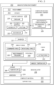
Figure 2 is an illustration of a block diagram of a manufacturing environment in accordance with an illustrative embodiment; -
Figure 3 is an illustration of a composite backing layer peel starter moving relative to a composite material in accordance with an illustrative embodiment; -
Figure 4 is an illustration of a composite backing layer peel starter moving relative to a composite material in accordance with an illustrative embodiment; -
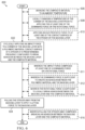
Figure 5 is a flowchart of a method of beginning removal of a backing layer from a composite material in accordance with an illustrative embodiment; -
Figure 6 is a flowchart of a method of beginning removal of a backing layer from a composite material in accordance with an illustrative embodiment; -
Figure 7 is an illustration of an aircraft manufacturing and service method in a form of a block diagram in accordance with an illustrative embodiment; and -
Figure 8 is an illustration of an aircraft in a form of a block diagram in which an illustrative embodiment may be implemented. - The illustrative examples recognize and take into account one or more considerations. The illustrative examples recognize and take into account that a variety of methods may be used to remove a backing material from a composite material. The illustrative examples recognize and take into account that methods to remove a backing material may undesirably disturb the composite ply. The illustrative examples recognize and take into account that having a free edge of backing material aids in beginning removal of the backing material from a composite material for any removal method.
- The illustrative examples present a composite backing layer peel starter. The composite backing layer peel starter may also be referred to as a "release initiator." The composite backing layer peel starter creates a free edge of backing material. Creating the free edge allows any form of automated backing removal to take place. The illustrative examples provide a composite backing layer peel starter comprising a rigid hammer and a striker connected to the rigid hammer, the striker comprising a polymeric material contact surface configured to adhere to a backing layer of a composite material.
- Turning now to
Figure 1 , an illustration of an aircraft is depicted in accordance with an illustrative embodiment.Aircraft 100 haswing 102 andwing 104 attached tobody 106.Aircraft 100 includesengine 108 attached towing 102 andengine 110 attached towing 104. -
Body 106 hastail section 112.Horizontal stabilizer 114,horizontal stabilizer 116, andvertical stabilizer 118 are attached totail section 112 ofbody 106. -
Aircraft 100 is an example of an aircraft that can have composite components formed using composite material after lifting a backing material using the illustrative examples. To manufacture a composite component, such as part ofwing 102 orwing 104, a composite backing layer peel starter of the illustrative examples can be used to lift a corner of a backing material on a composite ply. - Turning now to
Figure 2 , an illustration of a block diagram of a manufacturing environment is depicted in accordance with an illustrative embodiment. Composite backinglayer peel starter 200 is present inmanufacturing environment 202. Composite backinglayer peel starter 200 is configured to breakadhesion 204 ofcorner 206 ofbacking layer 208 oncomposite material 210. Composite backinglayer peel starter 200 is configured to locally breakadhesion 204 ofbacking layer 208 fromcomposite material 210. -
Contact surface 218 comprisespolymeric material 216 havingflexibility 222 configured to preserve a thickness ofcomposite material 210 in an area struck bycontact surface 218. - Composite backing
layer peel starter 200 comprisesrigid hammer 212 andstriker 214 connected torigid hammer 212.Striker 214 comprisespolymeric material 216contact surface 218 configured to adhere tobacking layer 208 ofcomposite material 210.Adhesion 221 betweencontact surface 218 andbacking layer 208 can be used to liftbacking layer 208 andcomposite material 210. - In some illustrative examples,
contact surface 218 comprisespolymeric material 216 havingflexibility 222 configured to createadhesion 221 betweenbacking layer 208 andpolymeric material 216. -
Striker 214 appliesforce 234 tocomposite material 210 to breakadhesion 204 betweenbacking layer 208 andcomposite material 210.Striker 214 appliesimpact force 236 to breakadhesion 204 through at least one ofdownward force 238 orrotational force 240.Rotational force 240 during impact can create shear to aid in breakingadhesion 204 betweenbacking layer 208 andcomposite material 210. In some illustrative examples,polymeric material 216 generatessufficient friction 232 againstbacking layer 208 to breakadhesion 204 withrotational force 240. -
Striker 214 applies liftingforce 242 to pullbacking layer 208 away fromcomposite material 210.Adhesion 221 betweencontact surface 218 andbacking layer 208further breaks adhesion 204 betweenbacking layer 208 andcomposite material 210 ascontact surface 218 is pulled away fromcomposite material 210 by liftingforce 242. - In some illustrative examples,
contact surface 218 comprisessuction cup 220.Suction cup 220 can generategreater adhesion 221 betweencontact surface 218 andbacking layer 208.Suction cup 220 allows forcontact surface 218 tobetter break adhesion 204 during liftingforce 242. - In some illustrative examples,
contact surface 218 is circular 224. In some illustrative examples,contact surface 218 is approximately 0,55 inch in diameter. - In some illustrative examples, composite backing
layer peel starter 200 further compriseselectrostatic force generator 226 configured to applyelectrostatic force 228 to one ofcontact surface 218 orbacking layer 208.Electrostatic force 228 can increase adhesion ofpolymeric material 216 ofcontact surface 218 tobacking layer 208. - In some illustrative examples,
composite material 210 is brought to anambient temperature 244 prior to applyingimpact force 236. In some illustrative examples,temperature 246 ofcorner 206 ofbacking layer 208 is locally changed prior to applyingimpact force 236. Locally changingtemperature 246 ofcorner 206 ofbacking layer 208 can include reducingtemperature 246 ofcorner 206 ofbacking layer 208. In some illustrative examples, changingtemperature 246 ofcorner 206 ofbacking layer 208 reducesadhesion 204 ofbacking layer 208 andcomposite material 210. In some illustrative examples, changingtemperature 246 ofcorner 206 ofbacking layer 208 allows foradhesion 204 betweenbacking layer 208 andcomposite material 210 to be more easily broken. -
Composite material 210 is present onsupport tool 230 when composite backinglayer peel starter 200 appliesimpact force 236.Support tool 230 can take any desirable form. In some illustrative examples,support tool 230 is a rigid tool, such as a cutting table. In some illustrative examples,composite material 210 is held againstsupport tool 230 by vacuum. - The illustration of
manufacturing environment 202 inFigure 2 is not meant to imply physical or architectural limitations to the manner in which an illustrative embodiment may be implemented. Other components in addition to or in place of the ones illustrated may be used. Some components may be unnecessary. Also, the blocks are presented to illustrate some functional components. One or more of these blocks may be combined, divided, or combined and divided into different blocks when implemented in an illustrative embodiment. - For example, in some illustrative examples,
suction cup 220 is optional. In some illustrative examples,rotational force 240 is optional. - As another example, force 234 can be repeatedly applied. In some illustrative examples,
impact force 236 ofcontact surface 218 againstbacking layer 208 is cyclically 248 applied atpredetermined frequency 250.Predetermined frequency 250 is configured to breakadhesion 204 betweenbacking layer 208 andcomposite material 210. In some illustrative examples,polymeric material 216contact surface 218 ofstriker 214 cyclically 248 appliesimpact force 236 to corner 206 ofbacking layer 208 atpredetermined frequency 250 configured to breakadhesion 204. - As yet another example, a coating can be applied to contact
surface 218 to increaseadhesion 221. In some illustrative examples, an adhesive or other coating can be added to contactsurface 218. In some illustrative examples, a coating may increase manufacturing time by having at least one of additional coating application, cleaning, removal, or reapplication steps. - Turning now to
Figure 3 , an illustration of a composite backing layer peel starter moving relative to a composite material is depicted in accordance with an illustrative embodiment. Inview 300 composite backinglayer peel starter 302 is acting uponcomposite material 304 to locally break adhesion 308 betweenbacking layer 306 andcomposite material 304. - Composite backing
layer peel starter 302 is a physical implementation of composite backinglayer peel starter 200 ofFigure 2 . Composite backinglayer peel starter 302 comprisesrigid hammer 312 andstriker 314 connected torigid hammer 312.Striker 314 comprises a polymeric material contact surface configured to adhere tobacking layer 306 ofcomposite material 304. - In some illustrative examples,
contact surface 322 comprises a polymeric material having a flexibility configured to cause adhesion between thebacking layer 306 and the polymeric material. In some illustrative examples,contact surface 322 is approximately 0,5 inch in diameter. In some illustrative examples,contact surface 322 is circular. - The polymeric material has a flexibility configured to preserve a thickness of
composite material 304 in an area struck bycontact surface 322. - In
view 300,contact surface 322 ofstriker 314 applies an impact force to corner 316 ofbacking layer 306. Inview 300, the impact force comprisesdownward force 318 sufficient to create an adhesion between the polymeric material ofstriker 314 andbacking layer 306. - As depicted, the impact force further comprises
rotational force 320.Rotational force 320 is a force of rotatingstriker 314 aboutrotational axis 321.Rotational axis 321 extends parallel torigid hammer 312.Rotational force 320 is applied to locally break adhesion 308 betweenbacking layer 306 andcomposite material 304. In some illustrative examples,rotational force 320 is optional. In some illustrative examples,rotational force 320 is applied whilecontact surface 322 is in contact withbacking layer 306. In some illustrative examples,rotational force 320 is applied whiledownward force 318 is applied tocomposite material 304.Rotational force 320 may be referred to as twisting.Rotational force 320 during the impact can create shear to aid in breaking adhesion 308 betweenbacking layer 306 andcomposite material 304 to breakbacking layer 306 loose. -
Composite material 304 is present onsupport tool 310 when composite backinglayer peel starter 302 applies the impact force.Support tool 310 can take any desirable form. In some illustrative examples,support tool 310 is a rigid tool, such as a cutting table. In some illustrative examples,composite material 304 is held againstsupport tool 310 by vacuum. - Turning now to
Figure 4 , an illustration of a composite backing layer peel starter moving relative to a composite material is depicted in accordance with an illustrative embodiment. Inview 400, composite backinglayer peel starter 302 is pullingstriker 314 away frombacking layer 306 to apply liftingforce 402 tobacking layer 306. - In
view 400, liftingforce 402 has liftedcorner 316 to form liftedcorner 404. Liftingforce 402 pullscorner 316 ofbacking layer 306 away fromcomposite material 304. Liftingforce 402 breaks any adhesion betweencontact surface 322 andbacking layer 306. - Turning now to
Figure 5 , a flowchart of a method of beginning removal of a backing layer from a composite material is depicted in accordance with an illustrative embodiment.Method 500 can be implemented in composite manufacturing for components inaircraft 100 ofFigure 1 .Method 500 can be performed using composite backinglayer peel starter 200 ofFigure 2 .Method 500 can be performed by composite backinglayer peel starter 302 ofFigures 3 and 4 . -
Method 500 applies an impact force to a corner of the backing layer with a polymeric material contact surface of a striker to adhere the polymeric material to the backing layer (operation 502).Method 500 pulls the striker away from the backing layer to apply a lifting force to the backing layer (operation 504). Afterwards,method 500 terminates. - In some illustrative examples,
method 500 locally reduces adhesion between the backing layer and the composite material prior to applying the impact force (operation 505). In some illustrative examples,method 500 brings the composite material to an ambient temperature prior to applying the impact force (operation 506). In some illustrative examples,method 500 locally changes a temperature of the corner of the backing layer prior to applying the impact force (operation 508). Locally changing the temperature of the corner of the backing layer can include reducing the temperature of the corner of the backing layer. In some illustrative examples, changing the temperature of the corner of the backing layer reduces the adhesion of the backing layer and the composite material. In some illustrative examples, changing the temperature of the corner of the backing layer allows for the adhesion between the backing layer and the composite material to be more easily broken. - In some illustrative examples,
method 500 applies an electrostatic force to at least one of the contact surface of the striker or the backing layer (operation 510). In these illustrative examples, the electrostatic force can increase an adhesion between the contact surface and the backing layer. Increasing the adhesion between the contact surface and the backing layer increases the force applied to the backing layer when the contact surface is lifted away from the backing layer. - In some illustrative examples, applying the impact force comprises cyclically applying the impact force at a predetermined frequency configured to break adhesion between the backing layer and the composite material (operation 511). In some illustrative examples, the impact force comprises a downward force sufficient to create an adhesion between the polymeric material and the backing layer (operation 512). In some illustrative examples, the impact force comprises a rotational force (operation 514). In some illustrative examples, applying the impact force comprises applying an impact force to the corner of the backing layer with a suction cup forming the contact surface, and wherein pulling the striker away comprises breaking an adhesion between the suction cup and the backing layer (operation 516).
- Turning now to
Figure 6 , a flowchart of a method of beginning removal of a backing layer from a composite material is depicted in accordance with an illustrative embodiment.Method 600 can be implemented in composite manufacturing for components inaircraft 100 ofFigure 1 .Method 600 can be performed using composite backinglayer peel starter 200 ofFigure 2 .Method 600 can be performed by composite backinglayer peel starter 302 ofFigures 3 and 4 . -
Method 600 cyclically applies an impact force to a corner of the backing layer with a polymeric material contact surface of a striker at a predetermined frequency configured to break adhesion between the backing layer and the composite material (operation 602).Method 600 pulls the striker away from the backing layer to apply a lifting force to the backing layer (operation 604). Afterwards,method 600 terminates. - In some illustrative examples,
method 600 brings the composite material to an ambient temperature (operation 606). In some illustrative examples,method 600 locally changes a temperature of the corner of the backing layer prior to applying the at least one of the downward force or the rotational force (operation 608). Locally changing the temperature of the corner of the backing layer can include reducing the temperature of the corner of the backing layer. In some illustrative examples, changing the temperature of the corner of the backing layer reduces the adhesion of the backing layer and the composite material. In some illustrative examples, changing the temperature of the corner of the backing layer allows for the adhesion between the backing layer and the composite material to be more easily broken. - In some illustrative examples,
method 600 applies an electrostatic force to at least one of the contact surface of the striker or the backing layer (operation 610). In these illustrative examples, the electrostatic force can increase an adhesion between the contact surface and the backing layer. Increasing the adhesion between the contact surface and the backing layer increases the force applied to the backing layer when the contact surface is lifted away from the backing layer. - In some illustrative examples, the impact force comprises at least one of a downward force or a rotational force (operation 611). In some illustrative examples, the downward force is sufficient to create an adhesion between the polymeric material and the backing layer (operation 612). In some illustrative examples, the rotational force is sufficient to locally break adhesion between the backing layer and the composite material (operation 614). In some illustrative examples, pulling the striker away comprises breaking an adhesion between the backing layer and the composite material (operation 616).
- As used herein, the phrase "at least one of," when used with a list of items, means different combinations of one or more of the listed items may be used and only one of each item in the list may be needed. For example, "at least one of item A, item B, or item C" may include, without limitation, item A, item A and item B, or item B. This example also may include item A, item B, and item C or item B and item C. Of course, any combinations of these items may be present. In other examples, "at least one of" may be, for example, without limitation, two of item A; one of item B; and ten of item C; four of item B and seven of item C; or other suitable combinations. The item may be a particular object, thing, or a category. In other words, at least one of means any combination of items and number of items may be used from the list but not all of the items in the list are required.
- As used herein, "a number of," when used with reference to items means one or more items.
- The flowcharts and block diagrams in the different depicted embodiments illustrate the architecture, functionality, and operation of some possible implementations of apparatuses and methods in an illustrative embodiment. In this regard, each block in the flowcharts or block diagrams may represent at least one of a module, a segment, a function, or a portion of an operation or step.
- In some alternative implementations of an illustrative embodiment, the function or functions noted in the blocks may occur out of the order noted in the figures. For example, in some cases, two blocks shown in succession may be executed substantially concurrently, or the blocks may sometimes be performed in the reverse order, depending upon the functionality involved. Also, other blocks may be added in addition to the illustrated blocks in a flowchart or block diagram. Some blocks may be optional. For example,
operation 506 throughoperation 518 may be optional. For example,operation 608 throughoperation 616 may be optional. - Illustrative embodiments of the present disclosure may be described in the context of aircraft manufacturing and
service method 700 as shown inFigure 7 andaircraft 800 as shown inFigure 8 . Turning first toFigure 7 , an illustration of an aircraft manufacturing and service method in a form of a block diagram is depicted in accordance with an illustrative embodiment. During pre-production, aircraft manufacturing andservice method 700 may include specification anddesign 702 ofaircraft 800 inFigure 8 andmaterial procurement 704. - During production, component and
subassembly manufacturing 706 andsystem integration 708 ofaircraft 800 takes place. Thereafter,aircraft 800 may go through certification anddelivery 710 in order to be placed inservice 712. While inservice 712 by a customer,aircraft 800 is scheduled for routine maintenance andservice 714, which may include modification, reconfiguration, refurbishment, or other maintenance and service. - Each of the processes of aircraft manufacturing and
service method 700 may be performed or carried out by a system integrator, a third party, and/or an operator. In these examples, the operator may be a customer. For the purposes of this description, a system integrator may include, without limitation, any number of aircraft manufacturers and major-system subcontractors; a third party may include, without limitation, any number of vendors, subcontractors, and suppliers; and an operator may be an airline, a leasing company, a military entity, a service organization, and so on. - With reference now to
Figure 8 , an illustration of an aircraft in a form of a block diagram is depicted in which an illustrative embodiment may be implemented. In this example,aircraft 800 is produced by aircraft manufacturing andservice method 700 ofFigure 7 and may includeairframe 802 with plurality ofsystems 804 and interior 806. Examples ofsystems 804 include one or more ofpropulsion system 808,electrical system 810,hydraulic system 812, andenvironmental system 814. Any number of other systems may be included. - Apparatuses and methods embodied herein may be employed during at least one of the stages of aircraft manufacturing and
service method 700. One or more illustrative embodiments may be manufactured or used during at least one of component andsubassembly manufacturing 706,system integration 708, inservice 712, or maintenance andservice 714 ofFigure 7 . - The illustrative examples present a composite backing layer peel starter. The composite backing layer peel starter can be referred to as an initiator. The composite backing layer peel starter comprises a small hammer that strikes the composite material quickly. In some illustrative examples, the quick striking comprises rotating. The striking breaks the adhesive bond between the backing material and the composite ply.
- The illustrative examples present a very fast and compact device. The illustrative examples do not require leverage to use. Striking the backing material to break the adhesive bond between the backing material and composite ply can include a twist during the strike. Twisting during the impact can create shear to aid in breaking the backing material loose. You could use a suction cup to increase the adhesive between the striker and the backing material. In some illustrative examples, an adhesive or other surface coating can be applied to the contact surface to increase the adhesion.
- The illustrative examples can be used in conjunction with any pick and place technology for composite prepreg. The illustrative examples create a free edge of backing material using a soft rubber striker to locally break tack adhesion from the composite material. In some illustrative examples, the rubber striker can be used as part of a pick and place system. In some illustrative examples, the rubber striker can be used separately from a pick and place system or other backing remover.
- In the illustrative examples, an impact is used to break adhesion between the backing material and the composite material. In some illustrative examples, the impact and an optional twisting motion are used to break adhesion. In some illustrative examples, the impact and an adhesion between the contact surface and the backing material are used to break adhesion. In some illustrative examples, an impact and then a suction cup adhesion of the hammer to the backing material can be used to break adhesion. In these illustrative examples, the optional suction device can increase adhesion to the backing material. In some illustrative examples, a cyclic impact of the hammer at a predetermined frequency is used to break adhesion. The hammering could be cycled at a predetermined frequency to break the adhesion.
- Further, the disclosure comprises embodiments according to the following clauses:
- Clause 1. A method of beginning removal of a backing layer from a composite material comprising:
- applying an impact force to a corner of the backing layer with a polymeric material contact surface of a striker to adhere the polymeric material to the backing layer; and
- pulling the striker away from the backing layer to apply a lifting force to the backing layer.
-
Clause 2. The method of clause 1, wherein the impact force comprises a downward force sufficient to create an adhesion between the polymeric material and the backing layer. - Clause 3. The method of
clause 1 or 2, wherein the impact force comprises a rotational force. - Clause 4. The method of any of clauses 1 to 3, wherein applying the impact force comprises applying an impact force to the corner of the backing layer with a suction cup forming the contact surface, and wherein pulling the striker away comprises breaking an adhesion between the suction cup and the backing layer.
- Clause 5. The method of any of clauses 1 to 4further comprising:
bringing the composite material to an ambient temperature prior to applying the impact force. - Clause 6. The method of clause 5 further comprising:
locally reducing adhesion between the backing layer and the composite material prior to applying the impact force. - Clause 7. The method of clause 5 or 6 further comprising:
locally changing a temperature of the corner of the backing layer prior to applying the impact force. - Clause 8. The method of any of clauses 1 to 7 further comprising:
applying an electrostatic force to at least one of the contact surface of the striker or the backing layer. - Clause 9. The method of any of clauses 1 to 8, wherein applying the impact force comprises cyclically applying the impact force at a predetermined frequency configured to break adhesion between the backing layer and the composite material.
- Clause 10. A composite backing layer peel starter comprising:
- a rigid hammer; and
- a striker connected to the rigid hammer, the striker comprising a polymeric material contact surface configured to adhere to a backing layer of a composite material.
- Clause 11. The composite backing layer peel starter of clause 10, wherein the contact surface comprises a suction cup.
- Clause 12. The composite backing layer peel starter of clause 10 or 11, wherein the contact surface comprises a polymeric material having a flexibility configured to create an adhesion between the backing layer and the polymeric material.
- Clause 13. The composite backing layer peel starter of any of clauses 10 to 12, wherein the contact surface is approximately 0,5 inch in diameter.
- Clause 14. The composite backing layer peel starter of any of clauses 10 to 13, wherein the contact surface is circular.
- Clause 15. The composite backing layer peel starter of any of clauses 10 to 14 further comprising:
an electrostatic force generator configured to apply an electrostatic force to the contact surface. - Clause 16. The composite backing layer peel starter of any of clauses 10 to 15, wherein the contact surface comprises a polymeric material having a flexibility configured to preserve a thickness of the composite material in an area struck by the contact surface.
- Clause 17. A method of beginning removal of a backing layer from a composite material comprising:
- cyclically applying an impact force to a corner of the backing layer with a polymeric material contact surface of a striker at a predetermined frequency configured to break adhesion between the backing layer and the composite material; and
- pulling the striker away from the backing layer to apply a lifting force to the backing layer.
- Clause 18. The method of clause 17, wherein the impact force comprises at least one of a downward force or a rotational force.
- Clause 19. The method of clause 18, wherein the downward force is sufficient to create an adhesion between the polymeric material and the backing layer.
- Clause 20. The method of clause 18 or 19, wherein the rotational force is sufficient to locally break adhesion between the backing layer and the composite material.
- Clause 21. The method of any of clauses 17 to 20, wherein pulling the striker away comprises breaking an adhesion between the backing layer and the composite material.
- Clause 22. The method of clause 18 further comprising:
locally changing a temperature of the corner of the backing layer prior to applying the at least one of the downward force or the rotational force. - Clause 23. The method of any of clauses 17 to 22 further comprising:
applying an electrostatic force to at least one of the contact surface of the striker or the backing layer. - Clause 24. The method of any of clauses 17 to 23 further comprising:
bringing the composite material to an ambient temperature. - The description of the different illustrative embodiments has been presented for purposes of illustration and description and is not intended to be exhaustive or limited to the embodiments in the form disclosed. Many modifications and variations will be apparent to those of ordinary skill in the art. Further, different illustrative embodiments may provide different features as compared to other illustrative embodiments. The embodiment or embodiments selected are chosen and described in order to best explain the principles of the embodiments, the practical application, and to enable others of ordinary skill in the art to understand the disclosure for various embodiments with various modifications as are suited to the particular use contemplated.
Claims (15)
- A method (500) of beginning removal of a backing layer (208, 306) from a composite material (210, 304) comprising:applying (502) an impact force (236) to a corner (206, 316) of the backing layer (208, 306) with a polymeric material (216) contact surface (218, 322) of a striker (214, 314) to adhere the polymeric material (216) to the backing layer (208, 306); andpulling (504) the striker (214, 314) away from the backing layer (208, 306) to apply a lifting force (242, 402) to the backing layer (208, 306).
- The method (500) of claim 1, wherein (512) the impact force (236) comprises a downward force (238, 318) sufficient to create an adhesion (221) between the polymeric material (216) and the backing layer (208, 306).
- The method (500) of claim 1 or 2, wherein (514) the impact force (236) comprises a rotational force (240, 320).
- The method (500) of any of claims 1 to 3, wherein (516) applying the impact force (236) comprises applying an impact force (236) to the corner (206, 316) of the backing layer (208, 306) with a suction cup (220) forming the contact surface (218, 322), and wherein (518) pulling the striker (214, 314) away comprises breaking an adhesion (221) between the suction cup (220) and the backing layer (208, 306).
- The method (500) of any of claims 1 to 4 further comprising:bringing (506) the composite material (210, 304) to an ambient temperature (244) prior to applying the impact force (236); andpreferably locally (505) reducing adhesion (204, 308) between the backing layer (208, 306) and the composite material (210, 304) prior to applying the impact force (236); and/orpreferably locally (508) changing a temperature (246) of the corner (206, 316) of the backing layer (208, 306) prior to applying the impact force (236).
- The method (500) of any of claims 1 to 5 further comprising:
applying (510) an electrostatic force (228) to at least one of the contact surface (218, 322) of the striker (214, 314) or the backing layer (208, 306). - The method (500) of any of claims 1 to 6, wherein (511) applying the impact force (236) comprises cyclically (248) applying the impact force (236) at a predetermined frequency (250) configured to break adhesion (204, 308) between the backing layer (208, 306) and the composite material (210, 304).
- A composite backing layer peel starter (200, 302) comprising:a rigid hammer (212, 312); anda striker (214, 314) connected to the rigid hammer (212, 312), the striker (214, 314) comprising a polymeric material (216) contact surface (218, 322) configured to adhere to a backing layer (208, 306) of a composite material (210, 304).
- The composite backing layer peel starter (200, 302) of claim 8, wherein the contact surface (218, 322) comprises a suction cup (220).
- The composite backing layer peel starter (200, 302) of claim 8 or 9, wherein the contact surface (218, 322) comprises a polymeric material (216) having a flexibility (222) configured to create an adhesion (221) between the backing layer (208, 306) and the polymeric material (216) .
- The composite backing layer peel starter (200, 302) of any of claims 8 to 10, wherein the contact surface (218, 322) is approximately 0,5 inch in diameter.
- The composite backing layer peel starter (200, 302) of any of claims 8 to 11, wherein the contact surface (218, 322) is circular.
- The composite backing layer peel starter (200, 302) of any of claims 8 to 12 further comprising:
an electrostatic force generator (226) configured to apply an electrostatic force (228) to the contact surface (218, 322). - The composite backing layer peel starter (200, 302) of any of claims 8 to 13, wherein the contact surface (218, 322) comprises a polymeric material (216) having a flexibility (222) configured to preserve a thickness of the composite material (210, 304) in an area struck by the contact surface (218, 322).
- A method (600) of beginning removal of a backing layer (208, 306) from a composite material (210, 304) comprising:cyclically applying (602) an impact force (236) to a corner (206, 316) of the backing layer (208, 306) with a polymeric material (216) contact surface (218, 322) of a striker (214, 314) at a predetermined frequency configured to break adhesion (204, 308) between the backing layer (208, 306) and the composite material (210, 304); andpulling (604) the striker (214, 314) away from the backing layer (208, 306) to apply a lifting force (242, 402) to the backing layer (208, 306).
Applications Claiming Priority (1)
| Application Number | Priority Date | Filing Date | Title |
|---|---|---|---|
| US18/490,558 US12623449B2 (en) | 2023-10-19 | 2023-10-19 | Composite backing layer peel starter |
Publications (1)
| Publication Number | Publication Date |
|---|---|
| EP4541564A1 true EP4541564A1 (en) | 2025-04-23 |
Family
ID=91968969
Family Applications (1)
| Application Number | Title | Priority Date | Filing Date |
|---|---|---|---|
| EP24190527.2A Pending EP4541564A1 (en) | 2023-10-19 | 2024-07-24 | Composite backing layer peel starter |
Country Status (2)
| Country | Link |
|---|---|
| US (1) | US12623449B2 (en) |
| EP (1) | EP4541564A1 (en) |
Citations (8)
| Publication number | Priority date | Publication date | Assignee | Title |
|---|---|---|---|---|
| WO2007082238A2 (en) * | 2006-01-10 | 2007-07-19 | Hard Hat Technology, Llc | A functional polymer faced hammer for reduced vibration, noise, and improved ergonomics |
| GB2490152A (en) * | 2011-04-20 | 2012-10-24 | Umeco Structural Materials Derby Ltd | Automated Prepreg Processing, removal of an external film |
| US20120330453A1 (en) * | 2011-06-22 | 2012-12-27 | The Boeing Company | Automated ply layup system |
| US20150314584A1 (en) * | 2014-04-30 | 2015-11-05 | The Boeing Company | System and method for automated initial separation of composite ply backing |
| US20190009513A1 (en) * | 2017-07-06 | 2019-01-10 | General Electric Company | System and method for removal of a layer |
| US20200148491A1 (en) * | 2018-10-15 | 2020-05-14 | General Electric Company | Systems and Methods of Automated Film Removal |
| US20200391497A1 (en) * | 2017-03-10 | 2020-12-17 | Mitsubishi Heavy Industries, Ltd. | Method of peeling protective sheet for prepreg sheet and apparatus for peeling protective sheet from prepreg sheet |
| US20210245491A1 (en) * | 2020-02-07 | 2021-08-12 | The Boeing Company | Apparatus and method for peeling a liner away from a substrate |
-
2023
- 2023-10-19 US US18/490,558 patent/US12623449B2/en active Active
-
2024
- 2024-07-24 EP EP24190527.2A patent/EP4541564A1/en active Pending
Patent Citations (8)
| Publication number | Priority date | Publication date | Assignee | Title |
|---|---|---|---|---|
| WO2007082238A2 (en) * | 2006-01-10 | 2007-07-19 | Hard Hat Technology, Llc | A functional polymer faced hammer for reduced vibration, noise, and improved ergonomics |
| GB2490152A (en) * | 2011-04-20 | 2012-10-24 | Umeco Structural Materials Derby Ltd | Automated Prepreg Processing, removal of an external film |
| US20120330453A1 (en) * | 2011-06-22 | 2012-12-27 | The Boeing Company | Automated ply layup system |
| US20150314584A1 (en) * | 2014-04-30 | 2015-11-05 | The Boeing Company | System and method for automated initial separation of composite ply backing |
| US20200391497A1 (en) * | 2017-03-10 | 2020-12-17 | Mitsubishi Heavy Industries, Ltd. | Method of peeling protective sheet for prepreg sheet and apparatus for peeling protective sheet from prepreg sheet |
| US20190009513A1 (en) * | 2017-07-06 | 2019-01-10 | General Electric Company | System and method for removal of a layer |
| US20200148491A1 (en) * | 2018-10-15 | 2020-05-14 | General Electric Company | Systems and Methods of Automated Film Removal |
| US20210245491A1 (en) * | 2020-02-07 | 2021-08-12 | The Boeing Company | Apparatus and method for peeling a liner away from a substrate |
Also Published As
| Publication number | Publication date |
|---|---|
| US20250128509A1 (en) | 2025-04-24 |
| US12623449B2 (en) | 2026-05-12 |
Similar Documents
| Publication | Publication Date | Title |
|---|---|---|
| JP5029601B2 (en) | Laminate manufacturing apparatus and method | |
| EP2331612B1 (en) | Wrinkle reduction in uncured composite laminates | |
| CN108946149B (en) | Method, system and end effector for taking and placing composite material | |
| US6190602B1 (en) | Method of manufacturing a perforated laminate | |
| US9358770B2 (en) | System and method for automated initial separation of composite ply backing | |
| EP0822057A1 (en) | A composite molding apparatus and method for high pressure co-cure molding of light-weight honeycomb core composite articles having ramped surfaces utilizing low density, stabilized ramped honeycomb cores and product formed thereby | |
| JP2009114615A (en) | Manufacturing method and apparatus | |
| EP3427934A1 (en) | Structural pre-cured repair patch for repair to highly loaded primary and secondary structural components | |
| CN105073405B (en) | Method of repairing adhered components and composite comprising adhered components | |
| US7347961B2 (en) | Method and system having a flowable pressure pad for consolidating an uncured laminate sheet in a cure process | |
| US12623449B2 (en) | Composite backing layer peel starter | |
| US9586344B2 (en) | Method and system of forming a releasable support and method of pre-cure removal of a composite laminate | |
| US20230088819A1 (en) | Vacuum bag-less composite repair systems and methods | |
| JP4821262B2 (en) | Reinforcing fiber laminate, preform, FRP, reinforcing fiber laminate manufacturing method and manufacturing apparatus thereof | |
| US8715553B2 (en) | Method and device for treating a surface of a fibre composite material | |
| EP4353456A2 (en) | Systems and methods for removing a backing from a ply of composite material | |
| WO2005016633A1 (en) | Method and system for utilizing low pressure for perforating and consolidating an uncured laminate sheet in one cycle of operation | |
| JP2024065003A (en) | Separation of film layers from composite prepregs | |
| EP3492517B1 (en) | Insertion of catalyst into dry fibers prior to resin impregnation | |
| EP4667180A1 (en) | Pick and place end effector | |
| US11890849B1 (en) | Methods and systems for initiating layer separation within a multilayer composite structure | |
| US12611825B2 (en) | Composite repair | |
| JP2003305741A (en) | Manufacturing method of laminated structure | |
| EP3921144A1 (en) | Composite material for lightening various structures | |
| EP4197719A1 (en) | Gripping apparatus and associated systems and methods for gripping flexible materials |
Legal Events
| Date | Code | Title | Description |
|---|---|---|---|
| PUAI | Public reference made under article 153(3) epc to a published international application that has entered the european phase |
Free format text: ORIGINAL CODE: 0009012 |
|
| STAA | Information on the status of an ep patent application or granted ep patent |
Free format text: STATUS: THE APPLICATION HAS BEEN PUBLISHED |
|
| AK | Designated contracting states |
Kind code of ref document: A1 Designated state(s): AL AT BE BG CH CY CZ DE DK EE ES FI FR GB GR HR HU IE IS IT LI LT LU LV MC ME MK MT NL NO PL PT RO RS SE SI SK SM TR |
|
| STAA | Information on the status of an ep patent application or granted ep patent |
Free format text: STATUS: REQUEST FOR EXAMINATION WAS MADE |
|
| 17P | Request for examination filed |
Effective date: 20250909 |
|
| STAA | Information on the status of an ep patent application or granted ep patent |
Free format text: STATUS: EXAMINATION IS IN PROGRESS |
|
| 17Q | First examination report despatched |
Effective date: 20251209 |