EP4541325A1 - Instrument for knee arthroplasty procedure - Google Patents
Instrument for knee arthroplasty procedure Download PDFInfo
- Publication number
- EP4541325A1 EP4541325A1 EP23204539.3A EP23204539A EP4541325A1 EP 4541325 A1 EP4541325 A1 EP 4541325A1 EP 23204539 A EP23204539 A EP 23204539A EP 4541325 A1 EP4541325 A1 EP 4541325A1
- Authority
- EP
- European Patent Office
- Prior art keywords
- spacer
- component
- tibia
- rotative
- instrument
- Prior art date
- Legal status (The legal status is an assumption and is not a legal conclusion. Google has not performed a legal analysis and makes no representation as to the accuracy of the status listed.)
- Pending
Links
Images


Classifications
-
- A—HUMAN NECESSITIES
- A61—MEDICAL OR VETERINARY SCIENCE; HYGIENE
- A61F—FILTERS IMPLANTABLE INTO BLOOD VESSELS; PROSTHESES; DEVICES PROVIDING PATENCY TO, OR PREVENTING COLLAPSING OF, TUBULAR STRUCTURES OF THE BODY, e.g. STENTS; ORTHOPAEDIC, NURSING OR CONTRACEPTIVE DEVICES; FOMENTATION; TREATMENT OR PROTECTION OF EYES OR EARS; BANDAGES, DRESSINGS OR ABSORBENT PADS; FIRST-AID KITS
- A61F2/00—Filters implantable into blood vessels; Prostheses, i.e. artificial substitutes or replacements for parts of the body; Appliances for connecting them with the body; Devices providing patency to, or preventing collapsing of, tubular structures of the body, e.g. stents
- A61F2/02—Prostheses implantable into the body
- A61F2/30—Joints
- A61F2/46—Special tools for implanting artificial joints
- A61F2/4657—Measuring instruments used for implanting artificial joints
-
- A—HUMAN NECESSITIES
- A61—MEDICAL OR VETERINARY SCIENCE; HYGIENE
- A61F—FILTERS IMPLANTABLE INTO BLOOD VESSELS; PROSTHESES; DEVICES PROVIDING PATENCY TO, OR PREVENTING COLLAPSING OF, TUBULAR STRUCTURES OF THE BODY, e.g. STENTS; ORTHOPAEDIC, NURSING OR CONTRACEPTIVE DEVICES; FOMENTATION; TREATMENT OR PROTECTION OF EYES OR EARS; BANDAGES, DRESSINGS OR ABSORBENT PADS; FIRST-AID KITS
- A61F2/00—Filters implantable into blood vessels; Prostheses, i.e. artificial substitutes or replacements for parts of the body; Appliances for connecting them with the body; Devices providing patency to, or preventing collapsing of, tubular structures of the body, e.g. stents
- A61F2/02—Prostheses implantable into the body
- A61F2/30—Joints
- A61F2/30721—Accessories
- A61F2/30724—Spacers for centering an implant in a bone cavity, e.g. in a cement-receiving cavity
-
- A—HUMAN NECESSITIES
- A61—MEDICAL OR VETERINARY SCIENCE; HYGIENE
- A61B—DIAGNOSIS; SURGERY; IDENTIFICATION
- A61B17/00—Surgical instruments, devices or methods
- A61B17/02—Surgical instruments, devices or methods for holding wounds open, e.g. retractors; Tractors
- A61B17/025—Joint distractors
-
- A—HUMAN NECESSITIES
- A61—MEDICAL OR VETERINARY SCIENCE; HYGIENE
- A61B—DIAGNOSIS; SURGERY; IDENTIFICATION
- A61B17/00—Surgical instruments, devices or methods
- A61B17/14—Surgical saws
- A61B17/15—Guides therefor
- A61B17/154—Guides therefor for preparing bone for knee prosthesis
- A61B17/155—Cutting femur
-
- A—HUMAN NECESSITIES
- A61—MEDICAL OR VETERINARY SCIENCE; HYGIENE
- A61F—FILTERS IMPLANTABLE INTO BLOOD VESSELS; PROSTHESES; DEVICES PROVIDING PATENCY TO, OR PREVENTING COLLAPSING OF, TUBULAR STRUCTURES OF THE BODY, e.g. STENTS; ORTHOPAEDIC, NURSING OR CONTRACEPTIVE DEVICES; FOMENTATION; TREATMENT OR PROTECTION OF EYES OR EARS; BANDAGES, DRESSINGS OR ABSORBENT PADS; FIRST-AID KITS
- A61F2/00—Filters implantable into blood vessels; Prostheses, i.e. artificial substitutes or replacements for parts of the body; Appliances for connecting them with the body; Devices providing patency to, or preventing collapsing of, tubular structures of the body, e.g. stents
- A61F2/02—Prostheses implantable into the body
- A61F2/30—Joints
- A61F2/38—Joints for elbows or knees
- A61F2/389—Tibial components
-
- A—HUMAN NECESSITIES
- A61—MEDICAL OR VETERINARY SCIENCE; HYGIENE
- A61F—FILTERS IMPLANTABLE INTO BLOOD VESSELS; PROSTHESES; DEVICES PROVIDING PATENCY TO, OR PREVENTING COLLAPSING OF, TUBULAR STRUCTURES OF THE BODY, e.g. STENTS; ORTHOPAEDIC, NURSING OR CONTRACEPTIVE DEVICES; FOMENTATION; TREATMENT OR PROTECTION OF EYES OR EARS; BANDAGES, DRESSINGS OR ABSORBENT PADS; FIRST-AID KITS
- A61F2/00—Filters implantable into blood vessels; Prostheses, i.e. artificial substitutes or replacements for parts of the body; Appliances for connecting them with the body; Devices providing patency to, or preventing collapsing of, tubular structures of the body, e.g. stents
- A61F2/02—Prostheses implantable into the body
- A61F2/30—Joints
- A61F2/46—Special tools for implanting artificial joints
- A61F2/4684—Trial or dummy prostheses
-
- A—HUMAN NECESSITIES
- A61—MEDICAL OR VETERINARY SCIENCE; HYGIENE
- A61B—DIAGNOSIS; SURGERY; IDENTIFICATION
- A61B17/00—Surgical instruments, devices or methods
- A61B17/16—Instruments for performing osteoclasis; Drills or chisels for bones; Trepans
- A61B17/17—Guides or aligning means for drills, mills, pins or wires
- A61B17/1739—Guides or aligning means for drills, mills, pins or wires specially adapted for particular parts of the body
- A61B17/1764—Guides or aligning means for drills, mills, pins or wires specially adapted for particular parts of the body for the knee
-
- A—HUMAN NECESSITIES
- A61—MEDICAL OR VETERINARY SCIENCE; HYGIENE
- A61B—DIAGNOSIS; SURGERY; IDENTIFICATION
- A61B17/00—Surgical instruments, devices or methods
- A61B17/02—Surgical instruments, devices or methods for holding wounds open, e.g. retractors; Tractors
- A61B17/025—Joint distractors
- A61B2017/0268—Joint distractors for the knee
-
- A—HUMAN NECESSITIES
- A61—MEDICAL OR VETERINARY SCIENCE; HYGIENE
- A61F—FILTERS IMPLANTABLE INTO BLOOD VESSELS; PROSTHESES; DEVICES PROVIDING PATENCY TO, OR PREVENTING COLLAPSING OF, TUBULAR STRUCTURES OF THE BODY, e.g. STENTS; ORTHOPAEDIC, NURSING OR CONTRACEPTIVE DEVICES; FOMENTATION; TREATMENT OR PROTECTION OF EYES OR EARS; BANDAGES, DRESSINGS OR ABSORBENT PADS; FIRST-AID KITS
- A61F2/00—Filters implantable into blood vessels; Prostheses, i.e. artificial substitutes or replacements for parts of the body; Appliances for connecting them with the body; Devices providing patency to, or preventing collapsing of, tubular structures of the body, e.g. stents
- A61F2/02—Prostheses implantable into the body
- A61F2/30—Joints
- A61F2/38—Joints for elbows or knees
-
- A—HUMAN NECESSITIES
- A61—MEDICAL OR VETERINARY SCIENCE; HYGIENE
- A61F—FILTERS IMPLANTABLE INTO BLOOD VESSELS; PROSTHESES; DEVICES PROVIDING PATENCY TO, OR PREVENTING COLLAPSING OF, TUBULAR STRUCTURES OF THE BODY, e.g. STENTS; ORTHOPAEDIC, NURSING OR CONTRACEPTIVE DEVICES; FOMENTATION; TREATMENT OR PROTECTION OF EYES OR EARS; BANDAGES, DRESSINGS OR ABSORBENT PADS; FIRST-AID KITS
- A61F2/00—Filters implantable into blood vessels; Prostheses, i.e. artificial substitutes or replacements for parts of the body; Appliances for connecting them with the body; Devices providing patency to, or preventing collapsing of, tubular structures of the body, e.g. stents
- A61F2/02—Prostheses implantable into the body
- A61F2/30—Joints
- A61F2002/30001—Additional features of subject-matter classified in A61F2/28, A61F2/30 and subgroups thereof
- A61F2002/30316—The prosthesis having different structural features at different locations within the same prosthesis; Connections between prosthetic parts; Special structural features of bone or joint prostheses not otherwise provided for
- A61F2002/30535—Special structural features of bone or joint prostheses not otherwise provided for
- A61F2002/30604—Special structural features of bone or joint prostheses not otherwise provided for modular
-
- A—HUMAN NECESSITIES
- A61—MEDICAL OR VETERINARY SCIENCE; HYGIENE
- A61F—FILTERS IMPLANTABLE INTO BLOOD VESSELS; PROSTHESES; DEVICES PROVIDING PATENCY TO, OR PREVENTING COLLAPSING OF, TUBULAR STRUCTURES OF THE BODY, e.g. STENTS; ORTHOPAEDIC, NURSING OR CONTRACEPTIVE DEVICES; FOMENTATION; TREATMENT OR PROTECTION OF EYES OR EARS; BANDAGES, DRESSINGS OR ABSORBENT PADS; FIRST-AID KITS
- A61F2/00—Filters implantable into blood vessels; Prostheses, i.e. artificial substitutes or replacements for parts of the body; Appliances for connecting them with the body; Devices providing patency to, or preventing collapsing of, tubular structures of the body, e.g. stents
- A61F2/02—Prostheses implantable into the body
- A61F2/30—Joints
- A61F2002/30001—Additional features of subject-matter classified in A61F2/28, A61F2/30 and subgroups thereof
- A61F2002/30316—The prosthesis having different structural features at different locations within the same prosthesis; Connections between prosthetic parts; Special structural features of bone or joint prostheses not otherwise provided for
- A61F2002/30535—Special structural features of bone or joint prostheses not otherwise provided for
- A61F2002/30604—Special structural features of bone or joint prostheses not otherwise provided for modular
- A61F2002/30607—Kits of prosthetic parts to be assembled in various combinations for forming different prostheses
-
- A—HUMAN NECESSITIES
- A61—MEDICAL OR VETERINARY SCIENCE; HYGIENE
- A61F—FILTERS IMPLANTABLE INTO BLOOD VESSELS; PROSTHESES; DEVICES PROVIDING PATENCY TO, OR PREVENTING COLLAPSING OF, TUBULAR STRUCTURES OF THE BODY, e.g. STENTS; ORTHOPAEDIC, NURSING OR CONTRACEPTIVE DEVICES; FOMENTATION; TREATMENT OR PROTECTION OF EYES OR EARS; BANDAGES, DRESSINGS OR ABSORBENT PADS; FIRST-AID KITS
- A61F2/00—Filters implantable into blood vessels; Prostheses, i.e. artificial substitutes or replacements for parts of the body; Appliances for connecting them with the body; Devices providing patency to, or preventing collapsing of, tubular structures of the body, e.g. stents
- A61F2/02—Prostheses implantable into the body
- A61F2/30—Joints
- A61F2002/30001—Additional features of subject-matter classified in A61F2/28, A61F2/30 and subgroups thereof
- A61F2002/30316—The prosthesis having different structural features at different locations within the same prosthesis; Connections between prosthetic parts; Special structural features of bone or joint prostheses not otherwise provided for
- A61F2002/30535—Special structural features of bone or joint prostheses not otherwise provided for
- A61F2002/30604—Special structural features of bone or joint prostheses not otherwise provided for modular
- A61F2002/30616—Sets comprising a plurality of prosthetic parts of different sizes or orientations
-
- A—HUMAN NECESSITIES
- A61—MEDICAL OR VETERINARY SCIENCE; HYGIENE
- A61F—FILTERS IMPLANTABLE INTO BLOOD VESSELS; PROSTHESES; DEVICES PROVIDING PATENCY TO, OR PREVENTING COLLAPSING OF, TUBULAR STRUCTURES OF THE BODY, e.g. STENTS; ORTHOPAEDIC, NURSING OR CONTRACEPTIVE DEVICES; FOMENTATION; TREATMENT OR PROTECTION OF EYES OR EARS; BANDAGES, DRESSINGS OR ABSORBENT PADS; FIRST-AID KITS
- A61F2/00—Filters implantable into blood vessels; Prostheses, i.e. artificial substitutes or replacements for parts of the body; Appliances for connecting them with the body; Devices providing patency to, or preventing collapsing of, tubular structures of the body, e.g. stents
- A61F2/02—Prostheses implantable into the body
- A61F2/30—Joints
- A61F2002/30001—Additional features of subject-matter classified in A61F2/28, A61F2/30 and subgroups thereof
- A61F2002/30667—Features concerning an interaction with the environment or a particular use of the prosthesis
- A61F2002/30672—Features concerning an interaction with the environment or a particular use of the prosthesis temporary
-
- A—HUMAN NECESSITIES
- A61—MEDICAL OR VETERINARY SCIENCE; HYGIENE
- A61F—FILTERS IMPLANTABLE INTO BLOOD VESSELS; PROSTHESES; DEVICES PROVIDING PATENCY TO, OR PREVENTING COLLAPSING OF, TUBULAR STRUCTURES OF THE BODY, e.g. STENTS; ORTHOPAEDIC, NURSING OR CONTRACEPTIVE DEVICES; FOMENTATION; TREATMENT OR PROTECTION OF EYES OR EARS; BANDAGES, DRESSINGS OR ABSORBENT PADS; FIRST-AID KITS
- A61F2/00—Filters implantable into blood vessels; Prostheses, i.e. artificial substitutes or replacements for parts of the body; Appliances for connecting them with the body; Devices providing patency to, or preventing collapsing of, tubular structures of the body, e.g. stents
- A61F2/02—Prostheses implantable into the body
- A61F2/30—Joints
- A61F2/46—Special tools for implanting artificial joints
- A61F2/4657—Measuring instruments used for implanting artificial joints
- A61F2002/4658—Measuring instruments used for implanting artificial joints for measuring dimensions, e.g. length
- A61F2002/4661—Measuring instruments used for implanting artificial joints for measuring dimensions, e.g. length for measuring thickness
Definitions
- the invention relates to a spacer instrument for use in a knee arthroplasty procedure.
- a spacer instrument allows evaluating an extension gap and/or flexion gap between a femur and a tibia or the respective implants.
- a first aspect of the description refers to a spacer instrument for use in a knee arthroplasty procedure, the spacer instrument comprising:
- Positioning on top of means not necessarily directly positioning on the resected proximal portion.
- Each spacer component can be positioned for example on a trial tibia plateau attached to the resected tibia, or a tibia implant attached to the resected tibia or together with the rotative tibia component directly on the resected proximal portion.
- the rotative tibia component comprises a thickness corresponding to a thickness of trial tibia plateau and/or tibia implant. Therefore, the rotative tibia component replaces the trial tibia plateau or the tibia implant at an early stage of the knee arthroplasty operation, before the trial tibia plateau or the tibia implant is attached to the resected tibia. Once the trial tibia plateau or the tibia implant is attached to the resected tibia, each spacer component can be positioned directly thereon without the rotative tibia component.
- the advantage of the inventive spacer instrument is that the instrument can be used to evaluate the extension and/or flexion gap at any stage of the knee arthroplasty procedure, for example at an early, before the trial tibia plateau or the tibia implant is attached to the resected tibia, or at a later stage, once the trial tibia plateau or the tibia implant is attached to the resected tibia.
- each spacer component is a plate-type component having a substantially planar distal surface and a substantially planar proximal surface.
- the two spacer components are for example connected via a connecting part of the carrier device.
- the connecting part is for example a bar-type part.
- the rotative tibia component is for example attached to the connecting part via the rotation mechanism.
- the rotation mechanism comprises a manually operable operating element, which allows unlocking of the rotative tibia component. It is required to manually actuate the rotation mechanism to unlock the rotative tibia component. Once the rotative tibia component is unlocked, the rotative tibia component is rotatable.
- the first position and the second position is a locked position
- the rotative tibia component is rotatable between the first position and the second position upon unlocking of the rotative tibia component via the operating element.
- the rotative tibia component can be rotated manually around a rotational axis.
- the rotation mechanism comprises a self-lock mechanism for automatically locking the rotative tibia component in the first position and in the second position.
- the self-lock mechanism is for example a snap-in mechanism, which locks automatically in the first and the second position. Once the rotative tibia component reaches the first or the second position, no manually actuation is required to lock the rotative tibia component in said position.
- the rotative tibia component might be plate-type component having a substantially planar distal surface and a substantially planar proximal surface.
- the rotative tibia component might be a hollow body at least enveloped by the distal surface, the proximal surface and a lateral surface.
- at least one of said surfaces might comprise one or more openings, for example through holes. Such openings might be beneficial for hygienic preparation and/or for material saving and/or weight saving.
- the rotative tibia component comprises a plate-type base with a substantially planar distal surface and at least a lateral wall protruding from the plate-type base in the proximal direction.
- the height of the lateral wall defines the thickness of the rotative tibia component.
- the plate-type base and or the lateral wall might comprise one or more openings, for example through holes. Such openings might be beneficial for hygienic preparation and/or for material saving and/or weight saving.
- the spacer instrument comprises connection means for releasably connecting a femur cut compensation component.
- a femur cut compensation component allows for using the spacer instrument before or after distal resection of femur by adding the femur cut compensation component.
- the connection means comprise a least one T-shaped groove, wherein the femur cut compensation component comprises a corresponding T-shaped member for engaging with the T-shaped groove.
- each of the spacer components of the spacer instrument comprises a T-shaped groove.
- the spacer instrument and/or the femur cut compensation component comprise mounting means for releasably mounting a femur cutting block including corresponding mounting means.
- the femur cutting block provides a cutting guide for femur resection.
- the spacer instrument comprises receiving means, in particular through holes, for releasably receiving an alignment rod.
- the spacer instrument comprises two, in particular elongated holes.
- the two long holes are placed on the connecting part of the carrier device each on one side of the rotation mechanism.
- the rotative tibia component might comprise corresponding receiving means, in particular a through hole.
- the alignment rod allows checking of the tibia mechanical axis alignment.
- a second aspect of the description refers to a set of spacer instruments comprising at least two spacer instruments according to any of the preceding claims, at least two spacer instruments each comprising a first spacer component comprising a first thickness and a second spacer component comprising a second thickness, the first thickness and the second thickness defining a pair of thicknesses for each spacer instrument, wherein the at least two spacer instruments of the set are differing by different pairs of thicknesses.
- a third aspect of the description refers to a kit of parts comprising at least one spacer instrument according to the embodiments, and at least one femur cut compensation plate and/or a cutting block and/or an alignment rod and/or at least one further instrument.
- a further instrument might be for example a measurement block or sizing instrument.
- Fig. 1 schematically depicts a spacer instrument 10 for use in a knee arthroplasty procedure.
- the spacer instrument positioned on top of a resected proximal portion 12 of a tibia 14.
- the spacer instrument 10 comprises a carrier device 16 with at least a first spacer component 18 and a second spacer component 20.
- the first spacer component 18 comprises a first thickness T1 and the second spacer component 20 comprises a second thickness T2.
- the first thickness T1 and the second thickness T2 are defining a pair of thickness, wherein the first thickness T1 is different from the second thickness T2.
- T1 or T2 can be 22mm.
- each spacer component 18, 20 is a plate-type component having a substantially planar distal surface 22 and a substantially planar proximal surface 24.
- Each of the spacer components 18, 20 is configured to be temporarily positioned on top of the resected proximal portion 12 of the tibia 14 during knee arthroplasty with the distal surface 22 facing the resected proximal portion 12 of the tibia 14.
- the two spacer components 18, 20 are connected via a connecting part 26 of the carrier device 16.
- the connecting part 26 is for example a bar-type part.
- the spacer instrument 10 comprises a rotative tibia component 28.
- the rotative tibia component 28 is rotatively attached to the spacer carrier device 16 via a rotation mechanism 30.
- the rotative tibia component 28 is movable in at least a first position and a second position.
- the first spacer component 18 is aligned above the rotative tibia component 28, see for example fig. 1 a) .
- the second spacer 20 component is aligned above the rotative tibia component 28, see for example fig. 1 b) . This allows that each of the spacer components 18, 20 can be temporarily positioned on top of the resected proximal portion 12 of the tibia 14 with or without the rotative tibia component 28.
- the first spacer component 18 is aligned above the rotative tibia component 28 and the first spacer component 18 and the rotative tibia component 28 are positioned together on top of the resected proximal portion 12 of the tibia 14.
- the rotative tibia component 28 replaces a trial tibia plateau 32 or a tibia implant at an early stage of the operation procedure.
- a thickness TT of the rotative tibia component 28 corresponds to a thickness TP of the trial tibia plateau 32 or the tibia implant, see Fig. 1 b) .
- the rotative tibia component 28 is moved into the second position and the second spacer component 20 is aligned above the rotative tibia component 28.
- the first spacer component 18 is positioned on top of the resected proximal portion 12 of the tibia 14 on a trial tibia plateau 32 or a tibia implant, which is attached to the resected tibia at a later stage of the operation procedure.
- the rotation mechanism 30 comprises a manually operable operating element 34, which allows unlocking of the rotative tibia component.
- the operating element 34 is for example a button. It is required to manually actuate the rotation mechanism 30 via the operating element 34 to unlock the rotative tibia component 28.
- manually actuation of the rotation mechanism 30 is done by manually pressing the operating element 34 in distal direction along the rotational axis 36.
- the rotative tibia component 28 is unlocked, the rotative tibia component is rotatable 28 around a rotation axis 36.
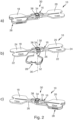
- the second position, see fig. 2 c) is a locked position.
- the rotative tibia component 28 can be rotated manually around the rotational axis 36, see fig. 2 b) .
- the rotation mechanism 30 is now explained with regard to fig. 3 .
- the operating element 34 is guided by a guiding part 38, which receives the operating element 34 and allows for moving the operating element 34 along the rotational axis 36 and for rotating the operating element 34 around the rotational axis 36.
- the rotative tibia 28 plate is fixed to the guiding part 38.
- the rotative tibia component 28 is fixed to the guiding part 38 via two pins 42 welded or glued into corresponding recesses 44, 46 of the rotative tibia component 28 and the guiding part 38.
- the rotation mechanism 30 comprises a self-lock mechanism for automatically locking the rotative tibia component in the first position and in the second position.
- the self-lock mechanism is realized via two protrusions 48 of the operating element 34 and a spring element 49.
- the two protrusions 48 are arranged in corresponding notches 50 of the guiding part 38 and the two protrusions extend through the notches 50 of the guiding part 38.
- the spring element 49 is arranged between the rotative tibia component 28 and the operating element 34.
- the spring force acts on the rotative tibia component 28 and the operating element 34 and results in pressing the operating element 34 in the proximal direction.
- the two protrusions 48 of the operating element 34 snap into corresponding pockets 51 of the carrier device 16, see fig. 3 b) and c) . Thereby, the rotative tibia component 28 is locked via the rotation mechanism 30 together with the carrier device 16.
- the self-lock mechanism locks automatically in the first and the second position by releasing the operating element 34 and no manually actuation is required to lock the rotative tibia component in said position.
- the protrusions 48 slide out of the pockets 51 of the carrier device 16, see fig. 3 d) and e), thereby allowing for rotating the rotative tibia component 28 manually around the rotational axis 36.
- the rotative tibia component 28 comprises a plate-type base 52 with a substantially planar distal surface 54 and at least a lateral wall 56 protruding from the plate-type base 52 in the proximal direction.
- the height of the lateral wall 56 defines the thickness TT of the rotative tibia component 28.
- the plate-type base 52 and the lateral wall 56 comprise a number of openings 58, for example through holes, see fig. 3 .
- Fig. 4 depicts a femur cut compensation component 60.
- the femur cut compensation component 60 can be releasably connected to the spacer instrument 10, for example to the first and/or the second spacer component 18, 20.
- the femur cut compensation component 60 allows for using the spacer instrument before or after distal resection of femur by adding the femur cut compensation component.
- the spacer instrument 10 comprises connection means for releasably connecting the femur cut compensation component 60.
- the connection means comprise a T-shaped groove 62 in each of the spacer components 18, 20, see fig. 5 a) to 5 c ).
- the femur cut compensation component 60 comprises a corresponding T-shaped member 64 for engaging with one of the T-shaped groove 62, see fig. 4 a) and b) .
- the spacer instrument 10, in particular the femur cut compensation component 60 may comprise mounting means (not displayed) for releasably mounting further instruments, for example a femur cutting block 68 including corresponding mounting means.
- the femur cutting block 68 provides a cutting guide for femur resection, see Fig. 6 a).
- Fig. 6 a) depicts a stage of the knee arthroplasty procedure before distal resection of femur 40.
- Fig. 6 b) depicts a stage of the knee arthroplasty procedure after distal resection of femur 40.
- the spacer instrument 10 comprises receiving means 70, in particular through holes, for releasably receiving an alignment rod (not displayed).
- the spacer instrument 10 comprises two, in particular elongated, holes 70.
- the two elongated holes 70 are placed on the connecting part 26 of the carrier device 16 each on one side of the rotation mechanism 30.
- the rotative tibia component 28 comprises corresponding receiving means 74, in particular a through hole.
- the alignment rod allows checking of the tibia 14 mechanical axis alignment.
- Further embodiments refer to a set of spacer instruments 10 comprising at least two spacer instruments 10 described with regard to figures 1 to 6 .
- the at least two spacer instruments 10 each comprising a first spacer component 18 with a first thickness T1 and a second spacer component 20 with a second thickness T2, the first thickness T1 and the second thickness T2 defining a pair of thicknesses (T1, T2) for each spacer instrument 10, wherein the at least two spacer instruments 10 of the set are differing by different pairs of thicknesses (T1, T2).
- kits of parts comprising at least one spacer instrument 10 described with regard to figures 1 to 6 , and at least one femur cut compensation plate 60 and/or a cutting block 68 and/or an alignment rod.
- a method for carrying out a knee arthroplasty procedure comprises the following steps: In a step of the procedure, the proximal portion 12 of a tibia 14 is prepared by resecting the proximal portion.
- an extension gap and/or flexion gap between the femur and the tibia is evaluated.
- the step of evaluating the extension gap and/or flexion gap might comprise positioning a spacer instrument 10, in particular a first spacer component 18 or a second spacer component 20 on the resected proximal portion 12.
- the first spacer component 18 or the second spacer component might be aligned above the rotative tibia component 28 such that the first spacer component 18 and the rotative tibia component 28 or the second spacer component 20 and the rotative tibia component 28 are positioned together on top of the resected proximal portion 12 of the tibia 14.
- the step of evaluating the extension gap and/or flexion gap might comprise rotating the rotative tibia component 28 from the first position to the second position and/or from a second position to the first position via the rotation mechanism 30.
- Rotating the rotative tibia component 28 might comprise manually operating the operating element 34, which allows unlocking of the rotative tibia component 28 and manually rotating the rotative tibia component 28.
- the first spacer component 18 or the second spacer component 20 might be positioned on the resected proximal portion 12 together with the rotative tibia component 28.
- a trial tibia plateau 32 or a tibia implant might be attached to the proximal portion 12 of the tibia 14.
- an extension gap and/or flexion gap between the femur and the tibia with the trial tibia plateau 32 or a tibia implant is evaluated using said spacer instrument 10.
- the first spacer component 18 or the second spacer component 20 might be positioned directly on the trial tibia plateau or a tibia implant without the rotative tibia component 28. Rotating of the rotative tibia component 28 might be carried out as described above.
Landscapes
- Health & Medical Sciences (AREA)
- Life Sciences & Earth Sciences (AREA)
- Orthopedic Medicine & Surgery (AREA)
- Transplantation (AREA)
- General Health & Medical Sciences (AREA)
- Veterinary Medicine (AREA)
- Engineering & Computer Science (AREA)
- Public Health (AREA)
- Heart & Thoracic Surgery (AREA)
- Biomedical Technology (AREA)
- Animal Behavior & Ethology (AREA)
- Oral & Maxillofacial Surgery (AREA)
- Surgery (AREA)
- Cardiology (AREA)
- Vascular Medicine (AREA)
- Physical Education & Sports Medicine (AREA)
- Nuclear Medicine, Radiotherapy & Molecular Imaging (AREA)
- Medical Informatics (AREA)
- Molecular Biology (AREA)
- Dentistry (AREA)
- Biophysics (AREA)
- Prostheses (AREA)
- Surgical Instruments (AREA)
Abstract
The disclosure refers to a spacer instrument (10) for use in a knee arthroplasty procedure, comprising:
a spacer carrier device (16) with at least a first spacer component (18) comprising a first thickness (T1) and a second spacer component (20) comprising a second thickness (T2), the first thickness (T1) being different than the second thickness (T2), and a rotative tibia component (28) rotatively attached to the spacer carrier device (16) via a rotation mechanism (30), wherein the rotative tibia component (28) is movable in at least a first position and
a second position, wherein in the first position the first spacer component (18) is aligned above the rotative tibia component (28) and wherein in the second position the second spacer component (20) is aligned above the rotative tibia component (28), such that each of the spacer components (18, 20) can be temporarily positioned on top of the resected proximal portion (12) of a tibia (14) with or without the rotative tibia component (28). (Fig. 1 a))
a spacer carrier device (16) with at least a first spacer component (18) comprising a first thickness (T1) and a second spacer component (20) comprising a second thickness (T2), the first thickness (T1) being different than the second thickness (T2), and a rotative tibia component (28) rotatively attached to the spacer carrier device (16) via a rotation mechanism (30), wherein the rotative tibia component (28) is movable in at least a first position and
a second position, wherein in the first position the first spacer component (18) is aligned above the rotative tibia component (28) and wherein in the second position the second spacer component (20) is aligned above the rotative tibia component (28), such that each of the spacer components (18, 20) can be temporarily positioned on top of the resected proximal portion (12) of a tibia (14) with or without the rotative tibia component (28). (Fig. 1 a))
Description
- The invention relates to a spacer instrument for use in a knee arthroplasty procedure. Such a spacer instrument allows evaluating an extension gap and/or flexion gap between a femur and a tibia or the respective implants.
- A first aspect of the description refers to a spacer instrument for use in a knee arthroplasty procedure, the spacer instrument comprising:
- a spacer carrier device with at least a first spacer component comprising a first thickness and a second spacer component comprising a second thickness, the first thickness being different than the second thickness, each of the spacer components being configured to be temporarily positioned on top of a resected proximal portion of a tibia during knee arthroplasty,
- and a rotative tibia component, wherein the rotative tibia component is rotatively attached to the spacer carrier device via a rotation mechanism, and the rotative tibia component is movable in at least a first position and a second position, wherein in the first position the first spacer component is aligned above the rotative tibia component and wherein in the second position the second spacer component is aligned above the rotative tibia component, such that each of the spacer components can be temporarily positioned on top of the resected proximal portion of a tibia with or without the rotative tibia component.
- Positioning on top of means not necessarily directly positioning on the resected proximal portion. Each spacer component can be positioned for example on a trial tibia plateau attached to the resected tibia, or a tibia implant attached to the resected tibia or together with the rotative tibia component directly on the resected proximal portion.
- The rotative tibia component comprises a thickness corresponding to a thickness of trial tibia plateau and/or tibia implant. Therefore, the rotative tibia component replaces the trial tibia plateau or the tibia implant at an early stage of the knee arthroplasty operation, before the trial tibia plateau or the tibia implant is attached to the resected tibia. Once the trial tibia plateau or the tibia implant is attached to the resected tibia, each spacer component can be positioned directly thereon without the rotative tibia component.
- The advantage of the inventive spacer instrument is that the instrument can be used to evaluate the extension and/or flexion gap at any stage of the knee arthroplasty procedure, for example at an early, before the trial tibia plateau or the tibia implant is attached to the resected tibia, or at a later stage, once the trial tibia plateau or the tibia implant is attached to the resected tibia.
- For example, each spacer component is a plate-type component having a substantially planar distal surface and a substantially planar proximal surface. The two spacer components are for example connected via a connecting part of the carrier device. The connecting part is for example a bar-type part. The rotative tibia component is for example attached to the connecting part via the rotation mechanism.
- Advantageously, the rotation mechanism comprises a manually operable operating element, which allows unlocking of the rotative tibia component. It is required to manually actuate the rotation mechanism to unlock the rotative tibia component. Once the rotative tibia component is unlocked, the rotative tibia component is rotatable.
- Advantageously, the first position and the second position is a locked position, and the rotative tibia component is rotatable between the first position and the second position upon unlocking of the rotative tibia component via the operating element. Upon unlocking of the rotative tibia component, the rotative tibia component can be rotated manually around a rotational axis.
- In some exemplary embodiments, the rotation mechanism comprises a self-lock mechanism for automatically locking the rotative tibia component in the first position and in the second position. The self-lock mechanism is for example a snap-in mechanism, which locks automatically in the first and the second position. Once the rotative tibia component reaches the first or the second position, no manually actuation is required to lock the rotative tibia component in said position.
- The rotative tibia component might be plate-type component having a substantially planar distal surface and a substantially planar proximal surface. The rotative tibia component might be a hollow body at least enveloped by the distal surface, the proximal surface and a lateral surface. According to an example, at least one of said surfaces might comprise one or more openings, for example through holes. Such openings might be beneficial for hygienic preparation and/or for material saving and/or weight saving.
- According to further preferred embodiments, the rotative tibia component comprises a plate-type base with a substantially planar distal surface and at least a lateral wall protruding from the plate-type base in the proximal direction. The height of the lateral wall defines the thickness of the rotative tibia component. The plate-type base and or the lateral wall might comprise one or more openings, for example through holes. Such openings might be beneficial for hygienic preparation and/or for material saving and/or weight saving.
- Advantageously, the spacer instrument comprises connection means for releasably connecting a femur cut compensation component. A femur cut compensation component allows for using the spacer instrument before or after distal resection of femur by adding the femur cut compensation component. According to an example, the connection means comprise a least one T-shaped groove, wherein the femur cut compensation component comprises a corresponding T-shaped member for engaging with the T-shaped groove. According to an example, each of the spacer components of the spacer instrument comprises a T-shaped groove.
- Advantageously, the spacer instrument and/or the femur cut compensation component comprise mounting means for releasably mounting a femur cutting block including corresponding mounting means. According to an example, the femur cutting block provides a cutting guide for femur resection.
- Advantageously, the spacer instrument comprises receiving means, in particular through holes, for releasably receiving an alignment rod. According to an example, the spacer instrument comprises two, in particular elongated holes. According to an example, the two long holes are placed on the connecting part of the carrier device each on one side of the rotation mechanism. The rotative tibia component might comprise corresponding receiving means, in particular a through hole. The alignment rod allows checking of the tibia mechanical axis alignment.
- A second aspect of the description refers to a set of spacer instruments comprising at least two spacer instruments according to any of the preceding claims, at least two spacer instruments each comprising a first spacer component comprising a first thickness and a second spacer component comprising a second thickness, the first thickness and the second thickness defining a pair of thicknesses for each spacer instrument, wherein the at least two spacer instruments of the set are differing by different pairs of thicknesses.
- A third aspect of the description refers to a kit of parts comprising at least one spacer instrument according to the embodiments, and at least one femur cut compensation plate and/or a cutting block and/or an alignment rod and/or at least one further instrument. A further instrument might be for example a measurement block or sizing instrument.
- Further advantageous embodiments are derivable from the following description of Exemplary embodiments with reference to the drawings. In the drawings:
- Fig. 1
- schematically depicts a spacer instrument positioned on top of a resected proximal portion of a tibia according to different stages of a knee arthroplasty procedure (a) and b));
- Fig. 2
- schematically depicts a spacer instrument in different operating situations (a), b) and c));
- Fig. 3
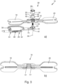
- schematically depicts a spacer instrument in an exploded view (a), a component of the spacer instrument (b) and detailed views of the spacer instrument (c), d) and e));
- Fig. 4
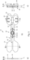
- schematically depicts a component of the spacer instrument in different views (a) and b));
- Fig. 5
- schematically depicts the component according to
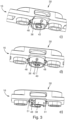
Fig. 4 attached to the spacer instrument in different views (a), b) and c)); - Fig. 6
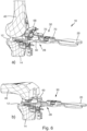
- schematically depicts a spacer instrument according to different stages of a knee arthroplasty procedure (a) and b)).
-
Fig. 1 schematically depicts aspacer instrument 10 for use in a knee arthroplasty procedure. According to the example, the spacer instrument positioned on top of a resectedproximal portion 12 of atibia 14. - The
spacer instrument 10 comprises acarrier device 16 with at least afirst spacer component 18 and asecond spacer component 20. Thefirst spacer component 18 comprises a first thickness T1 and thesecond spacer component 20 comprises a second thickness T2. The first thickness T1 and the second thickness T2 are defining a pair of thickness, wherein the first thickness T1 is different from the second thickness T2. According to an example, a pair of thickness can be chosen from the following pairs of thicknesses may be provided: a first pair with Tl=10 mm and T2=11mm, a further pair with T1=12 mm and T2=14mm, a further pair with T1=16 mm and T2=18mm. According to a further example, T1 or T2 can be 22mm. - According to the example, the each
spacer component distal surface 22 and a substantially planarproximal surface 24. Each of thespacer components proximal portion 12 of thetibia 14 during knee arthroplasty with thedistal surface 22 facing the resectedproximal portion 12 of thetibia 14. - The two
spacer components part 26 of thecarrier device 16. The connectingpart 26 is for example a bar-type part. - The
spacer instrument 10 comprises arotative tibia component 28. Therotative tibia component 28 is rotatively attached to thespacer carrier device 16 via arotation mechanism 30. - The
rotative tibia component 28 is movable in at least a first position and a second position. In the first position, thefirst spacer component 18 is aligned above therotative tibia component 28, see for examplefig. 1 a) . In the second position, thesecond spacer 20 component is aligned above therotative tibia component 28, see for examplefig. 1 b) . This allows that each of thespacer components proximal portion 12 of thetibia 14 with or without therotative tibia component 28. - According to
fig. 1 a) , thefirst spacer component 18 is aligned above therotative tibia component 28 and thefirst spacer component 18 and therotative tibia component 28 are positioned together on top of the resectedproximal portion 12 of thetibia 14. Therotative tibia component 28 replaces atrial tibia plateau 32 or a tibia implant at an early stage of the operation procedure. A thickness TT of therotative tibia component 28 corresponds to a thickness TP of thetrial tibia plateau 32 or the tibia implant, seeFig. 1 b) . - According to
fig. 1 b) , therotative tibia component 28 is moved into the second position and thesecond spacer component 20 is aligned above therotative tibia component 28. Thefirst spacer component 18 is positioned on top of the resectedproximal portion 12 of thetibia 14 on atrial tibia plateau 32 or a tibia implant, which is attached to the resected tibia at a later stage of the operation procedure. - The
rotation mechanism 30 comprises a manuallyoperable operating element 34, which allows unlocking of the rotative tibia component. The operatingelement 34 is for example a button. It is required to manually actuate therotation mechanism 30 via theoperating element 34 to unlock therotative tibia component 28. According to the example, manually actuation of therotation mechanism 30 is done by manually pressing theoperating element 34 in distal direction along therotational axis 36. Once therotative tibia component 28 is unlocked, the rotative tibia component is rotatable 28 around arotation axis 36. The first position, seefig. 2 a) , and the second position, seefig. 2 c) is a locked position. Upon unlocking of therotative tibia component 28, therotative tibia component 28 can be rotated manually around therotational axis 36, seefig. 2 b) . - The
rotation mechanism 30 is now explained with regard tofig. 3 . In the assembled state, the operatingelement 34 is guided by a guidingpart 38, which receives the operatingelement 34 and allows for moving the operatingelement 34 along therotational axis 36 and for rotating the operatingelement 34 around therotational axis 36. In the assembled state, therotative tibia 28 plate is fixed to the guidingpart 38. For example, therotative tibia component 28 is fixed to the guidingpart 38 via twopins 42 welded or glued into correspondingrecesses rotative tibia component 28 and the guidingpart 38. - The
rotation mechanism 30 comprises a self-lock mechanism for automatically locking the rotative tibia component in the first position and in the second position. According to the example, the self-lock mechanism is realized via twoprotrusions 48 of the operatingelement 34 and aspring element 49. The twoprotrusions 48 are arranged incorresponding notches 50 of the guidingpart 38 and the two protrusions extend through thenotches 50 of the guidingpart 38. - The
spring element 49 is arranged between therotative tibia component 28 and the operatingelement 34. The spring force acts on therotative tibia component 28 and the operatingelement 34 and results in pressing theoperating element 34 in the proximal direction. Once therotative tibia component 28 reaches the first or the second position and the operatingelement 34 is released, the twoprotrusions 48 of the operatingelement 34 snap into correspondingpockets 51 of thecarrier device 16, seefig. 3 b) andc) . Thereby, therotative tibia component 28 is locked via therotation mechanism 30 together with thecarrier device 16. - Therefore, the self-lock mechanism locks automatically in the first and the second position by releasing the operating
element 34 and no manually actuation is required to lock the rotative tibia component in said position. - By pressing the
operating element 34 in distal direction along therotational axis 36, theprotrusions 48 slide out of thepockets 51 of thecarrier device 16, seefig. 3 d) and e), thereby allowing for rotating therotative tibia component 28 manually around therotational axis 36. - According the example, the
rotative tibia component 28 comprises a plate-type base 52 with a substantially planardistal surface 54 and at least alateral wall 56 protruding from the plate-type base 52 in the proximal direction. The height of thelateral wall 56 defines the thickness TT of therotative tibia component 28. In the example, the plate-type base 52 and thelateral wall 56 comprise a number ofopenings 58, for example through holes, seefig. 3 . -
Fig. 4 depicts a femurcut compensation component 60. The femur cutcompensation component 60 can be releasably connected to thespacer instrument 10, for example to the first and/or thesecond spacer component compensation component 60 allows for using the spacer instrument before or after distal resection of femur by adding the femur cut compensation component. - The
spacer instrument 10 comprises connection means for releasably connecting the femurcut compensation component 60. According to the example, the connection means comprise a T-shapedgroove 62 in each of thespacer components fig. 5 a) to 5 c ). The femur cutcompensation component 60 comprises a corresponding T-shapedmember 64 for engaging with one of the T-shapedgroove 62, seefig. 4 a) and b) . - According to the example, the
spacer instrument 10, in particular the femurcut compensation component 60, may comprise mounting means (not displayed) for releasably mounting further instruments, for example afemur cutting block 68 including corresponding mounting means. According to an example, thefemur cutting block 68 provides a cutting guide for femur resection, seeFig. 6 a). Fig. 6 a) depicts a stage of the knee arthroplasty procedure before distal resection offemur 40.Fig. 6 b) depicts a stage of the knee arthroplasty procedure after distal resection offemur 40. - According to the example, the
spacer instrument 10 comprises receiving means 70, in particular through holes, for releasably receiving an alignment rod (not displayed). According to the example, thespacer instrument 10 comprises two, in particular elongated, holes 70. According to an example, the twoelongated holes 70 are placed on the connectingpart 26 of thecarrier device 16 each on one side of therotation mechanism 30. Therotative tibia component 28 comprises corresponding receiving means 74, in particular a through hole. The alignment rod allows checking of thetibia 14 mechanical axis alignment. Further embodiments refer to a set ofspacer instruments 10 comprising at least twospacer instruments 10 described with regard tofigures 1 to 6 . The at least twospacer instruments 10 each comprising afirst spacer component 18 with a first thickness T1 and asecond spacer component 20 with a second thickness T2, the first thickness T1 and the second thickness T2 defining a pair of thicknesses (T1, T2) for eachspacer instrument 10, wherein the at least twospacer instruments 10 of the set are differing by different pairs of thicknesses (T1, T2). - Further embodiments refer to a kit of parts comprising at least one
spacer instrument 10 described with regard tofigures 1 to 6 , and at least one femurcut compensation plate 60 and/or acutting block 68 and/or an alignment rod. - A method for carrying out a knee arthroplasty procedure comprises the following steps:
In a step of the procedure, theproximal portion 12 of atibia 14 is prepared by resecting the proximal portion. - In a step of the procedure, an extension gap and/or flexion gap between the femur and the tibia is evaluated.
- The step of evaluating the extension gap and/or flexion gap might comprise positioning a
spacer instrument 10, in particular afirst spacer component 18 or asecond spacer component 20 on the resectedproximal portion 12. Thefirst spacer component 18 or the second spacer component might be aligned above therotative tibia component 28 such that thefirst spacer component 18 and therotative tibia component 28 or thesecond spacer component 20 and therotative tibia component 28 are positioned together on top of the resectedproximal portion 12 of thetibia 14. - The step of evaluating the extension gap and/or flexion gap might comprise rotating the
rotative tibia component 28 from the first position to the second position and/or from a second position to the first position via therotation mechanism 30. Rotating therotative tibia component 28 might comprise manually operating the operatingelement 34, which allows unlocking of therotative tibia component 28 and manually rotating therotative tibia component 28. - After rotating the
rotative tibia component 28 from the first position to the second position and/or vice versa, thefirst spacer component 18 or thesecond spacer component 20 might be positioned on the resectedproximal portion 12 together with therotative tibia component 28. - In a step of the procedure, a
trial tibia plateau 32 or a tibia implant might be attached to theproximal portion 12 of thetibia 14. - In a further step of the procedure, an extension gap and/or flexion gap between the femur and the tibia with the
trial tibia plateau 32 or a tibia implant is evaluated using saidspacer instrument 10. Thefirst spacer component 18 or thesecond spacer component 20 might be positioned directly on the trial tibia plateau or a tibia implant without therotative tibia component 28. Rotating of therotative tibia component 28 might be carried out as described above.
Claims (10)
- A spacer instrument (10) for use in a knee arthroplasty procedure, comprising:
a spacer carrier device (16) with at least a first spacer component (18) comprising a first thickness (T1) and a second spacer component (20) comprising a second thickness (T2), the first thickness (T1) being different than the second thickness (T2), each of the spacer components (18, 20) being configured to be temporarily positioned on top of a resected proximal portion (12) of a tibia (14) during knee arthroplasty, and a rotative tibia component (28), wherein the rotative tibia component (28) is rotatively attached to the spacer carrier device (16) via a rotation mechanism (30), and the rotative tibia component (28) is movable in at least a first position and a second position, wherein in the first position the first spacer component (18) is aligned above the rotative tibia component (28) and wherein in the second position the second spacer component (20) is aligned above the rotative tibia component (28), such that each of the spacer components (18, 20) can be temporarily positioned on top of the resected proximal portion (12) of a tibia (14) with or without the rotative tibia component (28). - The spacer instrument (10) according to claim 1,
wherein each spacer component (18, 20) is a plate-type component having a substantially planar distal surface (22) and a substantially planar proximal surface (24) and/or the two spacer components are connected via a connecting part (26). - The spacer instrument (10) according to any of the preceding claims, wherein the rotation mechanism (30) comprises a manual operable operating element (34), which allows unlocking of the rotative tibia component (28) .
- The spacer instrument (10) according to claim 3,
wherein the first position and the second position is a locked position, and the rotative tibia component (28) is rotatable between the first position and the second position upon unlocking of the rotative tibia component (28) via the operating element (34). - The spacer instrument (10) according to any of the preceding claims, wherein the rotation mechanism (30) comprises a self-lock mechanism for automatically locking the rotative tibia component (28) in the first position and in the second position.
- The spacer instrument (10) according to any of the preceding claims, wherein the rotative tibia component (28) comprises a plate-type base (52) with a substantially planar distal surface (54) and at least a lateral wall (56) protruding from the plate-type base (52) in the proximal direction.
- The spacer instrument (10) according to any of the preceding claims, wherein the spacer instrument (10) comprises connection means (62) for releasably connecting a femur cut compensation component (60).
- The spacer instrument (10) according to any of the preceding claims, wherein the spacer instrument (10) comprises receiving means (70), in particular through holes, for releasably receiving an alignment rod.
- A set of spacer instruments (10) comprising at least two spacer instruments (10) according to any of the preceding claims, each comprising a first spacer component (18) comprising a first thickness (T1) and a second spacer component (20) comprising a second thickness (T2), the first thickness (T1) and the second thickness (T2) defining a pair of thicknesses (T1, T2) for each spacer instrument (10), wherein the at least two spacer instruments (10) of the set are differing by different pairs of thicknesses (T1, T2).
- A kit of parts comprising at least one spacer instrument (10) according to any of the preceding claims 1 to 8, and at least one femur cut compensation plate (60) and/or a cutting block (68) and/or an alignment rod and/or at least one further instrument.
Priority Applications (3)
| Application Number | Priority Date | Filing Date | Title |
|---|---|---|---|
| EP23204539.3A EP4541325A1 (en) | 2023-10-19 | 2023-10-19 | Instrument for knee arthroplasty procedure |
| US18/916,942 US20250127622A1 (en) | 2023-10-19 | 2024-10-16 | Instrument for knee arthroplasty procedure |
| JP2024180990A JP2025071017A (en) | 2023-10-19 | 2024-10-16 | Instruments for knee arthroplasty procedures |
Applications Claiming Priority (1)
| Application Number | Priority Date | Filing Date | Title |
|---|---|---|---|
| EP23204539.3A EP4541325A1 (en) | 2023-10-19 | 2023-10-19 | Instrument for knee arthroplasty procedure |
Publications (1)
| Publication Number | Publication Date |
|---|---|
| EP4541325A1 true EP4541325A1 (en) | 2025-04-23 |
Family
ID=88504860
Family Applications (1)
| Application Number | Title | Priority Date | Filing Date |
|---|---|---|---|
| EP23204539.3A Pending EP4541325A1 (en) | 2023-10-19 | 2023-10-19 | Instrument for knee arthroplasty procedure |
Country Status (3)
| Country | Link |
|---|---|
| US (1) | US20250127622A1 (en) |
| EP (1) | EP4541325A1 (en) |
| JP (1) | JP2025071017A (en) |
Citations (4)
| Publication number | Priority date | Publication date | Assignee | Title |
|---|---|---|---|---|
| WO2012004580A1 (en) * | 2010-07-07 | 2012-01-12 | Depuy (Ireland) | A surgical instrument |
| CN107233148A (en) * | 2016-03-28 | 2017-10-10 | 微创骨科医疗科技(苏州)有限公司 | Gap pad component |
| US20170340458A1 (en) * | 2011-06-06 | 2017-11-30 | Biomet Manufacturing, Llc | Method and apparatus for implanting a knee prosthesis |
| US20190380721A1 (en) * | 2018-06-18 | 2019-12-19 | Derek James Wallace McMinn | Multifunctional spacer for knee surgery to achieve balanced resection |
-
2023
- 2023-10-19 EP EP23204539.3A patent/EP4541325A1/en active Pending
-
2024
- 2024-10-16 JP JP2024180990A patent/JP2025071017A/en active Pending
- 2024-10-16 US US18/916,942 patent/US20250127622A1/en active Pending
Patent Citations (4)
| Publication number | Priority date | Publication date | Assignee | Title |
|---|---|---|---|---|
| WO2012004580A1 (en) * | 2010-07-07 | 2012-01-12 | Depuy (Ireland) | A surgical instrument |
| US20170340458A1 (en) * | 2011-06-06 | 2017-11-30 | Biomet Manufacturing, Llc | Method and apparatus for implanting a knee prosthesis |
| CN107233148A (en) * | 2016-03-28 | 2017-10-10 | 微创骨科医疗科技(苏州)有限公司 | Gap pad component |
| US20190380721A1 (en) * | 2018-06-18 | 2019-12-19 | Derek James Wallace McMinn | Multifunctional spacer for knee surgery to achieve balanced resection |
Also Published As
| Publication number | Publication date |
|---|---|
| US20250127622A1 (en) | 2025-04-24 |
| JP2025071017A (en) | 2025-05-02 |
Similar Documents
| Publication | Publication Date | Title |
|---|---|---|
| US8491587B2 (en) | Adjustable offset bushing | |
| US5941884A (en) | Patella preparation apparatus and method | |
| US5415663A (en) | Orthopaedic cutting guides with retractable saw blade slots | |
| US20210228382A1 (en) | Knee sizing and balancing instrument | |
| AU2017251689B2 (en) | A measuring instrument for use in orthopaedic surgery | |
| US6007537A (en) | Nested cutting block | |
| US4718413A (en) | Bone cutting guide and methods for using same | |
| US5676668A (en) | Femoral locating device assembly | |
| US5569263A (en) | Adjustable provisional articulating device | |
| AU717205B2 (en) | Surgical instrument | |
| US20040162561A1 (en) | Modular patella instrument | |
| US6080162A (en) | Modular orthopaedic clamping tool | |
| US20070162036A1 (en) | Device for assisting in a total knee prosthesis implantation | |
| EP0761172A1 (en) | Apparatus for correction of spaces between bone resection planes for knee prostheses | |
| EP4541325A1 (en) | Instrument for knee arthroplasty procedure | |
| US10792167B2 (en) | Surgical impactor/extractor assembly and method of use | |
| US6221035B1 (en) | Automatic ankle clamp | |
| JP7704884B2 (en) | Instrumentation and system including humeral cut guide assembly for orthopaedic shoulder replacement surgery - Patents.com | |
| US7648510B2 (en) | Adjustment apparatus | |
| JP2019509156A (en) | Surgical equipment for human knee surgery | |
| US20250041068A1 (en) | Patella trial implant | |
| US20060064104A1 (en) | Translating surgical mount | |
| JP4067813B2 (en) | Marking aid for total knee arthroplasty | |
| US20260102260A1 (en) | Surgical instrument system | |
| CA2246286A1 (en) | Posterior stabilized/constrained reamer guide |
Legal Events
| Date | Code | Title | Description |
|---|---|---|---|
| PUAI | Public reference made under article 153(3) epc to a published international application that has entered the european phase |
Free format text: ORIGINAL CODE: 0009012 |
|
| STAA | Information on the status of an ep patent application or granted ep patent |
Free format text: STATUS: THE APPLICATION HAS BEEN PUBLISHED |
|
| AK | Designated contracting states |
Kind code of ref document: A1 Designated state(s): AL AT BE BG CH CY CZ DE DK EE ES FI FR GB GR HR HU IE IS IT LI LT LU LV MC ME MK MT NL NO PL PT RO RS SE SI SK SM TR |
|
| STAA | Information on the status of an ep patent application or granted ep patent |
Free format text: STATUS: REQUEST FOR EXAMINATION WAS MADE |
|
| 17P | Request for examination filed |
Effective date: 20250813 |