EP4541250A2 - Cleaning device - Google Patents
Cleaning device Download PDFInfo
- Publication number
- EP4541250A2 EP4541250A2 EP23823194.8A EP23823194A EP4541250A2 EP 4541250 A2 EP4541250 A2 EP 4541250A2 EP 23823194 A EP23823194 A EP 23823194A EP 4541250 A2 EP4541250 A2 EP 4541250A2
- Authority
- EP
- European Patent Office
- Prior art keywords
- cleaning
- cleaning assembly
- assembly
- device body
- driving
- Prior art date
- Legal status (The legal status is an assumption and is not a legal conclusion. Google has not performed a legal analysis and makes no representation as to the accuracy of the status listed.)
- Pending
Links
Images


















Classifications
-
- A—HUMAN NECESSITIES
- A47—FURNITURE; DOMESTIC ARTICLES OR APPLIANCES; COFFEE MILLS; SPICE MILLS; SUCTION CLEANERS IN GENERAL
- A47L—DOMESTIC WASHING OR CLEANING; SUCTION CLEANERS IN GENERAL
- A47L11/00—Machines for cleaning floors, carpets, furniture, walls, or wall coverings
- A47L11/40—Parts or details of machines not provided for in groups A47L11/02 - A47L11/38, or not restricted to one of these groups, e.g. handles, arrangements of switches, skirts, buffers, levers
- A47L11/4063—Driving means; Transmission means therefor
- A47L11/4069—Driving or transmission means for the cleaning tools
-
- A—HUMAN NECESSITIES
- A47—FURNITURE; DOMESTIC ARTICLES OR APPLIANCES; COFFEE MILLS; SPICE MILLS; SUCTION CLEANERS IN GENERAL
- A47L—DOMESTIC WASHING OR CLEANING; SUCTION CLEANERS IN GENERAL
- A47L11/00—Machines for cleaning floors, carpets, furniture, walls, or wall coverings
- A47L11/28—Floor-scrubbing machines, motor-driven
- A47L11/282—Floor-scrubbing machines, motor-driven having rotary tools
-
- A—HUMAN NECESSITIES
- A47—FURNITURE; DOMESTIC ARTICLES OR APPLIANCES; COFFEE MILLS; SPICE MILLS; SUCTION CLEANERS IN GENERAL
- A47L—DOMESTIC WASHING OR CLEANING; SUCTION CLEANERS IN GENERAL
- A47L11/00—Machines for cleaning floors, carpets, furniture, walls, or wall coverings
- A47L11/24—Floor-sweeping machines, motor-driven
-
- A—HUMAN NECESSITIES
- A47—FURNITURE; DOMESTIC ARTICLES OR APPLIANCES; COFFEE MILLS; SPICE MILLS; SUCTION CLEANERS IN GENERAL
- A47L—DOMESTIC WASHING OR CLEANING; SUCTION CLEANERS IN GENERAL
- A47L11/00—Machines for cleaning floors, carpets, furniture, walls, or wall coverings
- A47L11/02—Floor surfacing or polishing machines
- A47L11/10—Floor surfacing or polishing machines motor-driven
- A47L11/14—Floor surfacing or polishing machines motor-driven with rotating tools
- A47L11/16—Floor surfacing or polishing machines motor-driven with rotating tools the tools being disc brushes
- A47L11/161—Floor surfacing or polishing machines motor-driven with rotating tools the tools being disc brushes with supply of cleaning agents
-
- A—HUMAN NECESSITIES
- A47—FURNITURE; DOMESTIC ARTICLES OR APPLIANCES; COFFEE MILLS; SPICE MILLS; SUCTION CLEANERS IN GENERAL
- A47L—DOMESTIC WASHING OR CLEANING; SUCTION CLEANERS IN GENERAL
- A47L11/00—Machines for cleaning floors, carpets, furniture, walls, or wall coverings
- A47L11/28—Floor-scrubbing machines, motor-driven
- A47L11/282—Floor-scrubbing machines, motor-driven having rotary tools
- A47L11/283—Floor-scrubbing machines, motor-driven having rotary tools the tools being disc brushes
-
- A—HUMAN NECESSITIES
- A47—FURNITURE; DOMESTIC ARTICLES OR APPLIANCES; COFFEE MILLS; SPICE MILLS; SUCTION CLEANERS IN GENERAL
- A47L—DOMESTIC WASHING OR CLEANING; SUCTION CLEANERS IN GENERAL
- A47L11/00—Machines for cleaning floors, carpets, furniture, walls, or wall coverings
- A47L11/40—Parts or details of machines not provided for in groups A47L11/02 - A47L11/38, or not restricted to one of these groups, e.g. handles, arrangements of switches, skirts, buffers, levers
-
- A—HUMAN NECESSITIES
- A47—FURNITURE; DOMESTIC ARTICLES OR APPLIANCES; COFFEE MILLS; SPICE MILLS; SUCTION CLEANERS IN GENERAL
- A47L—DOMESTIC WASHING OR CLEANING; SUCTION CLEANERS IN GENERAL
- A47L11/00—Machines for cleaning floors, carpets, furniture, walls, or wall coverings
- A47L11/40—Parts or details of machines not provided for in groups A47L11/02 - A47L11/38, or not restricted to one of these groups, e.g. handles, arrangements of switches, skirts, buffers, levers
- A47L11/4002—Installations of electric equipment
-
- A—HUMAN NECESSITIES
- A47—FURNITURE; DOMESTIC ARTICLES OR APPLIANCES; COFFEE MILLS; SPICE MILLS; SUCTION CLEANERS IN GENERAL
- A47L—DOMESTIC WASHING OR CLEANING; SUCTION CLEANERS IN GENERAL
- A47L11/00—Machines for cleaning floors, carpets, furniture, walls, or wall coverings
- A47L11/40—Parts or details of machines not provided for in groups A47L11/02 - A47L11/38, or not restricted to one of these groups, e.g. handles, arrangements of switches, skirts, buffers, levers
- A47L11/4011—Regulation of the cleaning machine by electric means; Control systems and remote control systems therefor
-
- A—HUMAN NECESSITIES
- A47—FURNITURE; DOMESTIC ARTICLES OR APPLIANCES; COFFEE MILLS; SPICE MILLS; SUCTION CLEANERS IN GENERAL
- A47L—DOMESTIC WASHING OR CLEANING; SUCTION CLEANERS IN GENERAL
- A47L11/00—Machines for cleaning floors, carpets, furniture, walls, or wall coverings
- A47L11/40—Parts or details of machines not provided for in groups A47L11/02 - A47L11/38, or not restricted to one of these groups, e.g. handles, arrangements of switches, skirts, buffers, levers
- A47L11/4013—Contaminants collecting devices, i.e. hoppers, tanks or the like
-
- A—HUMAN NECESSITIES
- A47—FURNITURE; DOMESTIC ARTICLES OR APPLIANCES; COFFEE MILLS; SPICE MILLS; SUCTION CLEANERS IN GENERAL
- A47L—DOMESTIC WASHING OR CLEANING; SUCTION CLEANERS IN GENERAL
- A47L11/00—Machines for cleaning floors, carpets, furniture, walls, or wall coverings
- A47L11/40—Parts or details of machines not provided for in groups A47L11/02 - A47L11/38, or not restricted to one of these groups, e.g. handles, arrangements of switches, skirts, buffers, levers
- A47L11/4036—Parts or details of the surface treating tools
- A47L11/4038—Disk shaped surface treating tools
-
- A—HUMAN NECESSITIES
- A47—FURNITURE; DOMESTIC ARTICLES OR APPLIANCES; COFFEE MILLS; SPICE MILLS; SUCTION CLEANERS IN GENERAL
- A47L—DOMESTIC WASHING OR CLEANING; SUCTION CLEANERS IN GENERAL
- A47L11/00—Machines for cleaning floors, carpets, furniture, walls, or wall coverings
- A47L11/40—Parts or details of machines not provided for in groups A47L11/02 - A47L11/38, or not restricted to one of these groups, e.g. handles, arrangements of switches, skirts, buffers, levers
- A47L11/4052—Movement of the tools or the like perpendicular to the cleaning surface
- A47L11/4055—Movement of the tools or the like perpendicular to the cleaning surface for lifting the tools to a non-working position
-
- A—HUMAN NECESSITIES
- A47—FURNITURE; DOMESTIC ARTICLES OR APPLIANCES; COFFEE MILLS; SPICE MILLS; SUCTION CLEANERS IN GENERAL
- A47L—DOMESTIC WASHING OR CLEANING; SUCTION CLEANERS IN GENERAL
- A47L11/00—Machines for cleaning floors, carpets, furniture, walls, or wall coverings
- A47L11/40—Parts or details of machines not provided for in groups A47L11/02 - A47L11/38, or not restricted to one of these groups, e.g. handles, arrangements of switches, skirts, buffers, levers
- A47L11/4052—Movement of the tools or the like perpendicular to the cleaning surface
- A47L11/4058—Movement of the tools or the like perpendicular to the cleaning surface for adjusting the height of the tool
-
- A—HUMAN NECESSITIES
- A47—FURNITURE; DOMESTIC ARTICLES OR APPLIANCES; COFFEE MILLS; SPICE MILLS; SUCTION CLEANERS IN GENERAL
- A47L—DOMESTIC WASHING OR CLEANING; SUCTION CLEANERS IN GENERAL
- A47L11/00—Machines for cleaning floors, carpets, furniture, walls, or wall coverings
- A47L11/40—Parts or details of machines not provided for in groups A47L11/02 - A47L11/38, or not restricted to one of these groups, e.g. handles, arrangements of switches, skirts, buffers, levers
- A47L11/4061—Steering means; Means for avoiding obstacles; Details related to the place where the driver is accommodated
-
- A—HUMAN NECESSITIES
- A47—FURNITURE; DOMESTIC ARTICLES OR APPLIANCES; COFFEE MILLS; SPICE MILLS; SUCTION CLEANERS IN GENERAL
- A47L—DOMESTIC WASHING OR CLEANING; SUCTION CLEANERS IN GENERAL
- A47L11/00—Machines for cleaning floors, carpets, furniture, walls, or wall coverings
- A47L11/40—Parts or details of machines not provided for in groups A47L11/02 - A47L11/38, or not restricted to one of these groups, e.g. handles, arrangements of switches, skirts, buffers, levers
- A47L11/408—Means for supplying cleaning or surface treating agents
-
- A—HUMAN NECESSITIES
- A47—FURNITURE; DOMESTIC ARTICLES OR APPLIANCES; COFFEE MILLS; SPICE MILLS; SUCTION CLEANERS IN GENERAL
- A47L—DOMESTIC WASHING OR CLEANING; SUCTION CLEANERS IN GENERAL
- A47L9/00—Details or accessories of suction cleaners, e.g. mechanical means for controlling the suction or for effecting pulsating action; Storing devices specially adapted to suction cleaners or parts thereof; Carrying-vehicles specially adapted for suction cleaners
- A47L9/02—Nozzles
- A47L9/04—Nozzles with driven brushes or agitators
- A47L9/0405—Driving means for the brushes or agitators
- A47L9/0411—Driving means for the brushes or agitators driven by electric motor
-
- A—HUMAN NECESSITIES
- A47—FURNITURE; DOMESTIC ARTICLES OR APPLIANCES; COFFEE MILLS; SPICE MILLS; SUCTION CLEANERS IN GENERAL
- A47L—DOMESTIC WASHING OR CLEANING; SUCTION CLEANERS IN GENERAL
- A47L9/00—Details or accessories of suction cleaners, e.g. mechanical means for controlling the suction or for effecting pulsating action; Storing devices specially adapted to suction cleaners or parts thereof; Carrying-vehicles specially adapted for suction cleaners
- A47L9/02—Nozzles
- A47L9/04—Nozzles with driven brushes or agitators
- A47L9/0461—Dust-loosening tools, e.g. agitators, brushes
- A47L9/0466—Rotating tools
- A47L9/0472—Discs
-
- A—HUMAN NECESSITIES
- A47—FURNITURE; DOMESTIC ARTICLES OR APPLIANCES; COFFEE MILLS; SPICE MILLS; SUCTION CLEANERS IN GENERAL
- A47L—DOMESTIC WASHING OR CLEANING; SUCTION CLEANERS IN GENERAL
- A47L2201/00—Robotic cleaning machines, i.e. with automatic control of the travelling movement or the cleaning operation
Definitions
- the present application relates to the field of cleaning devices, and in particular to a cleaning device.
- the cleaning device collects dirt on a surface to be cleaned mainly by means of a cleaning member such as a roller brush or cleaning cloth.
- the cleaning members of conventional cleaning devices are all designed to be fixed to a main unit, which results in an edge not being able to be mopped when performing an edgewise mopping, so that dirty marks are formed along an edge of a house wall over time, resulting in a poor user experience.
- An objective of the present application is to provide a cleaning device to solve the problem of insufficient edgewise cleaning.
- the present application provides a cleaning device, including: a device body; a cleaning assembly movably connected to the device body, the cleaning assembly having a first position and a second position, where a part of the cleaning assembly is located outside a peripheral side of the device body when the cleaning assembly is in the first position; and the part of the cleaning assembly that is located outside the peripheral side of the device body when the cleaning assembly is moved to the second position is larger than the part of the cleaning assembly that is located outside the peripheral side of the device body when the cleaning assembly is in the first position.
- the present application further provides is a cleaning device, including: a device body; a cleaning assembly movably connected to the device body, the cleaning assembly having an initial position and a retracted position; and a restoring member having one end connected to the cleaning assembly and the other end connected to the device body, the restoring member providing a restoring force for holding the cleaning assembly in the initial position, where a part of the cleaning assembly is located outside a peripheral side of the device body when the cleaning assembly is in the retracted position; and the part of the cleaning assembly that is located outside the peripheral side of the device body when the cleaning assembly is in the initial position is larger than the part of the cleaning assembly that is located outside the peripheral side of the device body when the cleaning assembly is in the retracted position, and the cleaning assembly switches from the initial position to the retracted position when the part of the cleaning assembly that is located outside the peripheral side of the device body abuts against an edge of an obstacle.
- the present application further provides a cleaning mechanism adapted to be mounted on the bottom of a body of a cleaning robot, the cleaning mechanism including: a cleaning member configured to clean a surface to be cleaned; a connection member including a first end configured for connection with the cleaning member and a second end configured for rotational connection with the body; and a driving assembly connected to the connection member and configured to drive the connection member to rotate about a fulcrum of the second end on the body, so as to drive the cleaning member to perform a lifting movement relative to the body.
- the present application further provides a cleaning mechanism, including: a base; a cleaning assembly including a cleaning member, the cleaning member being rotatable relative to the base under an external force such that the cleaning member has an inwardly retracted position or an outwardly extended position; and a first driving assembly, including a first driving member, a transmission member connected to the first driving member, a swing member cooperating with the transmission member, and an actuation member, where the swing member is rotatably arranged on the base; the cleaning member is arranged on the swing member; the actuation member is rotatably arranged on a spindle; two ends of the actuation member act on the swing member and the transmission member, respectively; the swing member cooperates with the transmission member and is driven to rotate by the transmission member, so as to switch the cleaning member between the inwardly retracted position and the outwardly extended position; during the switching of the cleaning member from the inwardly retracted position to the outwardly extended position, the actuation member stores energy under a driving force of the transmission
- the present application further provides a cleaning apparatus arranged on a main body of a cleaning robot, the cleaning apparatus including: a housing; a driving mechanism arranged in the housing; a cleaning assembly arranged at an output end of the driving mechanism, the driving mechanism driving the cleaning assembly to perform rotation and lifting movements; and an adjustment assembly arranged on the main body, the adjustment assembly being deformable under an external force such that the housing swings in a direction closer to the main body.
- the present application further provides a pulling mechanism for a cleaning module of a cleaning robot, the pulling mechanism including: a base body; a pulling member arranged at the base body, one end of the pulling member extending beyond the base body and being configured for connection with the cleaning module; a tensioning structure connected between two ends of the pulling member and configured to tension the pulling member; and a winding and unwinding assembly arranged at the base body and fixedly connected to the other end of the pulling member, the winding and unwinding assembly being configured to wind up the pulling member to pull the cleaning module, or to unwind the pulling member to release the cleaning module.
- the present application further provides a cleaning mechanism, including: a cleaning module including a driving module and a cleaning assembly, the driving module being connected to the cleaning assembly for driving the cleaning assembly to rotate; a connection member connected to the driving module; and a transmission member connected to the connection member and rotatably connected to the driving module, where the transmission member is rotatable about an axis of rotation to rotate the driving module about the axis of rotation in a linked manner by means of the connection member, the axis of rotation being parallel to an axis of rotation of the cleaning assembly.
- the present application further provides a cleaning robot, including: an enclosure; a cleaning module, including a cleaning assembly and a driving module for driving the cleaning assembly to rotate, the driving module being rotatably arranged in the enclosure such that the cleaning assembly has an initial position and an edgewise position, the edgewise position being a position in which at least a part of the cleaning assembly extends beyond a maximum width portion of the enclosure in a forward direction; an elastic member arranged between the enclosure and the driving module and causing the cleaning assembly to move toward the edgewise position by means of the driving module; and a linkage driving mechanism arranged at the enclosure and connected to the driving module for driving the driving module to rotate, where the linkage driving mechanism is capable of maintaining the cleaning assembly in the initial position when the linkage driving mechanism is self-locked.
- the present application further provides a sweeping control method for a cleaning robot, the method including: obtaining obstacle information in a forward direction of the cleaning robot, where the cleaning robot includes a body and a cleaning assembly movably arranged on the body, the cleaning assembly having a retracted position close to the body and an extended position away from the body, and a part of the cleaning assembly that is located outside a peripheral side of the body when the cleaning assembly is in the extended position is larger than the part of the cleaning assembly that is located outside the peripheral side of the body when the cleaning assembly is in the retracted position; determining whether the obstacle information contains obstacle data that meets a preset obstacle condition; and controlling movement of the cleaning assembly to the retracted position if the obstacle information contains the obstacle data that meets a preset obstacle condition.
- the present application has the following beneficial effects.
- the cleaning device includes a device body and a cleaning assembly, the cleaning assembly being movably connected to the device body, and the cleaning assembly having a first position and a second position, where a part of the cleaning assembly is located outside a peripheral side of the device body when the cleaning assembly is in the first position; and the part of the cleaning assembly that is located outside the peripheral side of the device body when the cleaning assembly is moved to the second position is larger than the part of the cleaning assembly that is located outside the peripheral side of the device body when the cleaning assembly is in the first position.
- the cleaning assembly has a first position and a second position during cleaning of a surface to be cleaned by the cleaning assembly, where the cleaning assembly moves in a direction away from the device body when switching from the first position to the second position, the part of the cleaning assembly that is located outside the device body when the cleaning assembly is in the second position is increased compared to when in the first position, to achieve cleaning of a region near the obstacle.
- the cleaning assembly when the cleaning assembly is in the first position and in the second position, the cleaning assembly is at least partially located outside the peripheral side of the device body, and when in the second position, cleaning is achieved at a blind spot such as the obstacle, the cleaning is more comprehensive, and the cleaning efficiency is improved.
- a cleaning device may be a sweeping robot, a mopping robot, a sweeping and mopping robot, a window wiping robot, etc.
- the cleaning device may include a device body 10, a travel system 300M, a cleaning module, a control system, a sensing system, etc.
- a mounting cavity is provided in the device body 10 and allows for the mounting of some structures.
- the outer shape of the device body 10 is not limited, and may be, but is not limited to, circular, D-shaped, triangular, or other shapes.
- the travel system 300M is arranged on the device body 10 for driving the device body 10 to implement a self-moving travel function on a surface to be cleaned.
- the travel system 300M generally includes a driver and a travel component.
- the driver drives the travel component to move.
- the travel components may be, but are not limited to, driving wheels, track wheels, or steering adjustable steering wheels.
- the steering wheels are Mecanum wheels.
- the travel system 300M is swingably arranged on the device body 10 to provide the cleaning device with an obstacle crossing function during travel.
- the surface to be cleaned may be, but is not limited to, a surface or scenario of an object such as a floor, a tabletop, glass, or a wall.
- a width direction of the device body is perpendicular to a travel direction of the device body 10.
- the maximum width of the device body 10 is defined as Wmax in the travel direction of the device body.
- the cleaning module includes either a dry cleaning module 100M or a wet cleaning module 200M, or both a dry cleaning module 100M and a wet cleaning module 200M.
- the dry cleaning module 100M includes a main brush 101M, a dust box 102M and a fan 103M, and a main brush cavity is provided at the bottom of the device body 10.
- the main brush 101M is rotatably arranged in the main brush cavity, a dust suction port on the main brush cavity is in communication with a dust inlet 1021M of the dust box 102M, and an air discharge port 1022M of the dust box 102M is in communication with the fan 103M.
- the main brush 101M moves the garbage around and in front of it to the dust suction port where the garbage is sucked into the dust box 102M under a negative pressure generated by the fan 103M, to achieve the function of cleaning the surface to be cleaned.
- the wet cleaning module 200M includes a first driving structure 40M, and a cleaning assembly 20.
- the cleaning assembly 20 includes a cleaning disk 90H and a cleaning member 91H arranged on the bottom of the cleaning disk 90H, and the first driving structure 40M drives the cleaning disk 90H to move, so as to drive the cleaning member 91H to oscillate reciprocally or rotate.
- the cleaning member 91H is rubbed against the floor during movement to clean the floor. Since the cleaning member 91H has an improved cleaning effect on the floor when in a wet state, a water replenishment mechanism is generally provided in the device body 10 of the cleaning device.
- the water replenishment mechanism includes a water tank, a solution in the water tank is delivered to the cleaning member 91H by means of a pump to wet the cleaning member 91H.
- a solution in the water tank is delivered to the cleaning member 91H by means of a pump to wet the cleaning member 91H.
- the two wet cleaning modules 200M are symmetrically arranged on the device body 10. Of course, one or more than two, such as three, four, five or more, wet cleaning modules 200M may be provided. The specific number of wet cleaning modules 200M is selected as needed, and is not specifically limited here.
- sweeping may be performed before mopping, and the wet cleaning module 200M is then located behind the dry cleaning module 100M in the forward direction of the cleaning device; or when the cleaning device performs a cleaning task, mopping may be performed before sweeping, and the wet cleaning module 200M is then located in front of the dry cleaning module 100M in the forward direction of the cleaning device.
- the wet cleaning module 200M is preferentially arranged behind the travel system 300M, to prevent, after the wet cleaning module 200M cleans the floor first, the travel components from traveling on the cleaned floor and contaminating the cleaned floor. If the floor cleaned by the wet cleaning module 200M can be dried in a timely manner, it is possible that the wet cleaning module 200M is arranged in front of the travel components, or that the wet cleaning module 200M is arranged between the two travel components.
- the sensing system includes sensing apparatuses such as an LDS located above the body, a buffer and a vision sensor located at the front portion of the device body 10, an edgewise sensor located at a side wall of the front portion of the device body 10, and an ultrasonic sensor located at the bottom of the device body 10.
- the LDS, the buffer and the edgewise sensor can all perform distance measurement to obtain a distance between an edge of the device body 10 and an obstacle, and the control system controls the cleaning device to perform a corresponding action on the basis of this distance. For example, the cleaning device is controlled to avoid the obstacle, move along an edge, etc.
- the ultrasonic sensor is configured to identify a carpet signal, and the control system controls the cleaning member 91H of the wet cleaning module 200M of the cleaning device to perform a raising action, or controls the cleaning device to return to a base station to remove the cleaning member 91H of the wet cleaning module 200M.
- the vision sensor is configured to identify an image of the environment in which the cleaning device is located in order to obtain information of the obstacle, and the control system controls the cleaning device to perform an action such as obstacle avoidance, obstacle crossing and edgewise cleaning on the basis of this information.
- the two wet cleaning modules 200M of the cleaning device in the prior art are fixedly arranged relative to the device body 10 in the width direction W0 of the device body 10 (perpendicular to the travel direction of the cleaning device), and the cleaning disk 90H and the cleaning member 91H in each wet cleaning module 200M can rotate or oscillate relative to the device body 10, so that when the cleaning device performs edgewise cleaning on the obstacle, the wet cleaning module 200M close to the obstacle side has difficulty in getting close to the edge of the obstacle to perform the edgewise cleaning on the obstacle, resulting in a large uncleaned region at the edge of the obstacle and unsatisfactory cleaning effect.
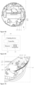
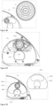
- At least one wet cleaning module 200M of the two wet cleaning modules 200M in this embodiment can swing relative to the device body 10, and the cleaning assembly 20 of the wet cleaning module 200M can swing outwardly in a direction away from the device body 10 and retract inwardly in a direction closer to the device body 10.
- the cleaning assembly 20 has a second position (i.e., an outwardly swung position) when swung outwardly, and the cleaning assembly 20 is correspondingly in an outwardly swung state.
- the cleaning assembly 20 has a first position when swung inwardly (i.e., an inwardly retracted position), and the cleaning assembly 20 is correspondingly in an inwardly retracted state.
- the outwardly swung position and the inwardly retracted position may each be a fixed position or a range of positions.
- a part of the cleaning assembly 20 is located outside a peripheral side of the device body 10 when the cleaning assembly 20 is in the first position.
- the part of the cleaning assembly 20 that is located outside the peripheral side of the device body 10 when the cleaning assembly 20 is moved to the second position is larger than the part of the cleaning assembly 20 that is located outside the peripheral side of the device body 10 when the cleaning assembly 20 is in the first position.
- a sensor of the sensing system measures in real time a first distance between the device body 10 and the edge of the obstacle. If the first distance is less than or equal to a preset threshold, it is necessary to perform the edgewise cleaning on the obstacle, the cleaning assembly 20 of the wet cleaning module 200M needs to swing outwardly, and the cleaning assembly 20 swings outwardly from the inwardly retracted position to the outwardly swung position to perform the edgewise cleaning on the edge of the obstacle.
- the cleaning assembly 20 can extend beyond the device body 10 by a greater distance in the outwardly swung position than in the inwardly retracted position, the cleaning assembly 20 can be closer to or adjacent to the edge of the obstacle in the outwardly swung position to perform the edgewise cleaning on the edge of the obstacle, to reduce or avoid the uncleaned region during the edgewise cleaning on the obstacle.
- the cleaning assembly 20 is continuously held in the outwardly swung position, the cleaning assembly 20 is susceptible to interference or disturbance by the obstacle in the environment, resulting in a risk of the cleaning assembly 20 falling off the device body 10. Therefore, the cleaning assembly 20 of the wet cleaning module 200M is generally swung toward the outside of the device body 10 and in the outwardly swung state when needing the edgewise cleaning. When the cleaning device is not used for edgewise cleaning or is in other scenarios, the cleaning assembly 20 tends to remain in the inwardly retracted state.
- the other scenarios may include, but are not limited to, the cleaning device needing to be returned to the base station where the cleaning device is charged, dust within the dust box 102M is collected in a dust bin of the base station, the cleaning member 91H is washed, the cleaning member 91H is removed and/or mounted, water is filled into the water tank of the water replenishment mechanism within the cleaning device, etc.; or the cleaning member 91H of the cleaning device needing to be raised, the cleaning device needing to cross and avoid the obstacle.
- the cleaning assembly 20 may also be held in the outwardly swung state in other scenarios as described above.
- the device body 10 is further provided with a second driving structure 50M.
- the second driving structure 50M may directly drive the cleaning assembly 20 to swing or may indirectly drive the cleaning assembly 20 to swing by driving the entire wet cleaning module 200M.
- the second driving structure 50M driving the cleaning assembly 20 to swing is temporarily used as an example to illustrate a driving force generated by the second driving structure 50M for swinging the cleaning assembly 20.
- this driving force is also suitable for driving the entire wet cleaning module 200M to swing.
- the second driving structure 50M may drive the cleaning assembly 20 to move in a straight line or in an arc, so as to switch the cleaning assembly 20 between the outwardly swung position and the inwardly retracted position.
- the driving force of the second driving structure 50M for driving the cleaning assembly 20 to swing may be implemented in a variety of ways, and only some of the implementations will be particularly described below.
- the outward swinging and inward retraction of the cleaning assembly 20 are both driven by a motor, and since the angle of rotation of the motor is controllable, the outwardly swung position and the inwardly retracted position of the cleaning assembly 20 can be controlled by controlling the angle of rotation of the motor, so that the outwardly swung position and the inwardly retracted position of the cleaning assembly 20 can be adjusted.
- an edgewise distance is dynamically adjusted on the basis of the first distance between the device body 10 and the edge of the obstacle that is measured by the sensor in real time.
- the outward swinging of the cleaning assembly 20 is driven by the cooperation of a motor and an elastic member, and the inward retraction of the cleaning assembly 20 is driven by the motor. If the cleaning device needs to perform an edgewise cleaning, the motor rotates in a first direction to drive the cleaning assembly 20 to swing by an angle ⁇ 1 and then to stop, and the elastic member then releases the stored energy to drive the cleaning assembly 20 to continue to swing toward the outside of the device body 10 by an angle ⁇ 2 .
- the cleaning assembly 20 can automatically swing toward the inside of the device body 10, to dynamically adjust the angle ⁇ 2 of the outward swinging of the cleaning assembly 20, so that the edgewise distance can be dynamically adjusted while protecting the cleaning assembly 20.
- the motor rotates in a second direction, to drive the cleaning assembly 20 to swing toward the inside of the device body 10 by an angle ⁇ 3 , where ⁇ 3 may be equal to the sum of the angle ⁇ 1 and the angle ⁇ 2 , or may be not equal to the sum of the angle ⁇ 1 and the angle ⁇ 2 .
- the inwardly retracted position of the cleaning assembly 20 is adjusted by controlling the angle of rotation of the motor in the second direction. Furthermore, it should be noted that the magnitude of the angle ⁇ 2 depends on the energy released by the elastic member. If the energy released by the elastic member is small, the outward swinging driving force of the cleaning assembly 20 mainly relies on the motor, and the elastic member mainly functions to cushion the cleaning assembly 20. On the contrary, if the energy released by the elastic member is large, the elastic member not only functions to cushion the cleaning assembly 20, but also functions to drive the outward swinging of the cleaning assembly 20.
- the driving force of the motor simultaneously applies a driving force on the elastic member to cause the elastic member to store energy, so that the elastic member releases the stored energy to drive the cleaning assembly 20 to continue to swing outwardly after the driving force of the motor is canceled.
- the second driving structure 50M includes a second motor 204M and a second transmission mechanism 202M, and the elastic member is arranged between the second transmission mechanism 202M and the cleaning assembly 20.
- the second motor 204M drives the cleaning assembly 20 to swing outwardly
- the second motor 204M rotates in the first direction, to drive the second transmission mechanism 202M to rotate in the first direction
- the second transmission mechanism 202M applies a force on the elastic member, forcing the elastic member to store energy.
- the elastic member may store energy before driving the cleaning assembly 20 to swing outwardly, or the elastic member may drive the cleaning assembly 20 to swing outwardly while storing energy, and when the motor is stalled, the elastic member releases the stored energy to drive the cleaning assembly 20 to continue to swing outwardly.
- the elastic member may be a deformable elastic member such as a tension spring, a compression spring, or a torsion spring.
- the motor rotates in the second direction, through the hard abutment relationship between the second transmission mechanism 202M and the cleaning assembly 20.
- the second transmission mechanism 202M is provided with a first abutting portion and the cleaning assembly 20 is provided with a second abutting portion.
- the first abutting portion abuts against the second abutting portion, so that the second motor 204M drives the second transmission mechanism 202M to rotate, so as to rotate the cleaning assembly 20 toward the inwardly retracted position to achieve the inwardly swung state.
- the outward swinging of the cleaning assembly 20 is driven by a motor, and the inward retraction of the cleaning assembly 20 is driven by an elastic member.
- the rotation of the motor drives the cleaning assembly 20 to swing outwardly, to bring the cleaning assembly 20 into the outwardly swung state.
- the cleaning assembly 20 may be limited in the outwardly swung position by providing a limiting structure or a locking structure.
- the cleaning assembly 20 needs to retract inwardly, the force of the limiting structure or the locking structure on the cleaning assembly 20 is canceled, and the cleaning assembly 20 automatically swings inwardly to the inwardly retracted position under the restoring force of the elastic member.
- the outward swinging of the cleaning assembly 20 is driven by a motor, and the inward retraction of the cleaning assembly 20 is driven by the cooperation of the motor and an elastic member.
- the rotation of the motor drives the cleaning assembly 20 to swing outwardly, to bring the cleaning assembly 20 into the outwardly swung state.
- the motor first drives the cleaning assembly 20 to retract inwardly by a certain angle, and the elastic member stores energy during this process.
- the elastic member releases the stored energy to drive the cleaning assembly 20 to continue to swing inwardly to the inwardly retracted position.
- the outward swinging of the cleaning assembly 20 is driven by the elastic member, and the inward retraction of the cleaning assembly 20 is driven by the motor. That is, when the motor is not operating, the cleaning assembly 20 tends to remain in the outwardly swung position under the action of the elastic member.
- the elastic member is preferably a tension spring or a compression spring if the second driving structure 50M drives the cleaning assembly 20 or the wet cleaning module 200M to swing in a straight line.
- the elastic member is preferably a torsion spring if the second driving structure 50M drives the cleaning assembly 20 or the wet cleaning module 200M to swing in an arc.
- the cleaning assembly 20 can be driven to the outwardly swung position or the inwardly retracted position upon the motor rotating for a theoretical preset time period T1.
- the control system controls the motor to rotate for a time period T2, where the preset time period T3 may be any second.
- the preset time period T3 may be selected from 0 to 10 seconds.
- the preset time period T3 is 1 second, 2 seconds, 3 seconds, 4 seconds, 5 seconds, 6 seconds, 9 seconds, 10 seconds, etc.
- the cleaning device further includes an in-place detection structure.
- the in-place detection structure may be a micro-switch, a Hall sensor, an optocoupler switch, etc.
- the in-place detection structure can obtain the position of the cleaning assembly 20 by detecting the position of the motor of the second driving structure 50M.
- the position of the cleaning assembly 20 can be detected directly.
- the second driving structure 50M includes a motor and a transmission mechanism
- the in-place detection structure may obtain the position of the cleaning assembly 20 by detecting the position of the transmission mechanism.
- the second driving structure 50M includes a motor and a transmission mechanism, one of a detection member and a sensing member of the in-place detection structure is provided on the transmission mechanism and the other thereof is fixedly arranged relative to the device body 10, and the detection member and the sensing member are located in a rotational path of the transmission mechanism. If, during rotation of the transmission mechanism, the detection member detects a signal from the sensing member that indicates that the cleaning assembly 20 is in the inwardly retracted position or in the outwardly swung position or in the arbitrary position, the control system controls the motor to be stalled on the basis of this signal.
- the second driving structure 50M includes the second motor 204M and the second transmission mechanism 202M, and the in-place detection structure detects the position of the second transmission mechanism 202M due to the cushioning effect of the elastic member on the outward swinging of the cleaning assembly 20.
- the control system controls the second motor 204M to stall.
- the cleaning assembly 20 is acted upon by the elastic member, and the outwardly swung position of the cleaning assembly 20 is changed by an abutting force of the edge of the obstacle. If the edge of the obstacle is a straight edge, the outwardly swung position of the cleaning assembly 20 is a fixed position.
- the outwardly swung position of the cleaning assembly 20 is a dynamically varying value, so the specific position of the cleaning assembly 20 is not directly detected. If, during the outward swinging or inward retraction, the cleaning assembly 20 is not cushioned by the elastic member, the in-place detection structure may detect the position of the motor or the position of the transmission mechanism of the second driving structure 50M, so that the position of the cleaning assembly 20 can be obtained.
- the cleaning device is further provided with a limiting structure arranged on the second driving structure 50M or the first driving structure, or on a swing path of the cleaning assembly 20.
- a limiting structure arranged on the second driving structure 50M or the first driving structure, or on a swing path of the cleaning assembly 20.
- the cleaning device is further provided with a locking structure for locking the cleaning assembly 20 in the inwardly retracted position or the outwardly swung position such that the cleaning assembly 20 can always remain in the outwardly swung position or the inwardly retracted position, or an arbitrary position during swinging.
- the locking structure cancels the locking effect on the cleaning assembly 20, and the cleaning assembly 20 swings under the drive of the second driving structure 50M.
- the locking structure may be arranged on the second driving structure 50M, or on the first driving structure of the wet cleaning module 200M, or on the cleaning assembly 20.
- the motor of the second driving structure 50M takes the form of a brushed motor, which has a braking function.
- the control system sends a braking signal to the brushed motor, and the brushed motor locks itself, to lock the cleaning assembly 20 in the inwardly retracted position.
- the cleaning assembly 20 is locked in the outwardly swung position by the self-locking function of the brushed motor.
- the cleaning assembly 20 needs to be in the inwardly retracted position, when the locking structure or the brushed motor is employed, before performing the actions in other scenarios as described above, the cleaning assembly 20 is locked in the inwardly retracted position using the locking structure or the brushed motor, and when the cleaning assembly 20 needs to swing outwardly, the locking effect on the cleaning assembly 20 is canceled.
- the cleaning device prevents the wet cleaning member 91H from wetting the carpet.
- the cleaning member 91H in a dirty state is prevented from contaminating the floor.
- the cleaning device is further provided with a lifting structure configured to drive the cleaning assembly 20 to be raised and lowered.
- the first driving structure 40M for driving the rotation of the cleaning assembly 20 is also used for driving the lifting structure to rotate synchronously.
- the lifting structure drives the entire wet cleaning module 200M to be raised and lowered
- the second driving structure 50M drives the lifting structure to swing, so as to drive the wet cleaning module 200M to swing.
- the lifting structure may be implemented in a variety of ways.
- the lifting structure may be a gear and rack pair, a threaded lifting mechanism, an air cylinder, a lead screw, a worm gear and worm pair, etc.
- the lifting structure may be divided into at least two cases. In a first case, the lifting structure is raised and lowered by driving the cleaning assembly 20 to rotate, and correspondingly, during the outward swinging and inward retraction of the cleaning assembly 20, the cleaning assembly 20 remains non-rotating. In a second case, during the process of the lifting structure driving the cleaning assembly 20 to be raised and lowered, the cleaning assembly 20 does not rotate, and accordingly, during the outward swinging and inward retraction of the cleaning assembly 20, the cleaning assembly 20 may or may not rotate.
- the lifting structure and the first driving structure 40M may share one motor.
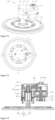
- the first driving structure 40M includes a rotary motor 2011M.
- the lifting structure includes a first fixing body 2012M and a second fixing body 2013M.
- the first fixing body 2012M threadedly mates with the second fixing body 2013M, and one of the first fixing body 2012M and the second fixing body 2013M is provided with a threaded groove, and the other thereof has a rib or thread that mates with the threaded groove.
- the bottom of the second fixing body 2013M is provided with a mounting portion 2001H, and the top of the cleaning disk 90H is connected to the mounting portion 2001H.
- the mounting portion 2001H is provided with a first magnet 2014M
- the cleaning disk 90H is provided with a second magnet 2015M, such that the cleaning disk 90H is fixed to the mounting portion 2001H by the magnetic attraction of the first magnet 2014M and the second magnet 2015M.
- the cleaning assembly 20 in FIG. 100 is in a mopping position, and when it is necessary to raise the cleaning assembly 20, the rotary motor 2011M rotates in a first direction, the second fixing body 2013M rotates upwardly relative to the first fixing body 2012M, and the cleaning assembly 20 is raised to a raised position. If the rotary motor 2011M continues to rotate in the first direction, the second fixing body 2013M continues to rotate upwardly relative to the first fixing body 2012M, and the cleaning assembly 20 is raised to a separated position. In this case, the cleaning assembly 20 is separated from the mounting portion 2001H, during which the cleaning disk 90H rotates.
- the rotary motor 2011M rotates in a second direction, which is opposite to the first direction
- the second fixing body 2013M rotates downwardly relative to the first fixing body 2012M
- the cleaning assembly 20 is lowered from the separated position to the raised position and then to the mopping position, during which the cleaning disk 90H rotates.
- the second fixing body 2013M no longer rotates relative to the first fixing body 2012M
- the rotary motor 2011M continues to rotate in the second direction, there is no relative rotation between the first fixing body 2012M and the second fixing body 2013M, so that the cleaning assembly 20 can be driven to rotate as a whole to mop the floor.
- the rotational direction of the cleaning assembly 20 during raising is different from the rotational direction during lowering.
- the provision of the separated position is to facilitate the return of the cleaning device to the base station for automatic removal and mounting of the cleaning member 91H.
- the cleaning assembly is automatically removed from the device body. If the automatic removal and mounting function of the cleaning member 91H is not required, the cleaning assembly 20 can be provided with the mopping position and the raised position without the separated position.
- a common motor drives the structure of rotation and lifting of the cleaning assembly 20, and the cleaning assembly 20 does not rotate during the outward swinging or inward retraction of the cleaning assembly 20 of the cleaning device.
- the control system controls the cleaning assembly 20 to retract to the inwardly retracted position before the lifting structure performs a raising movement.
- the cleaning assembly 20 does not rotate during the inward retraction.
- the cleaning assembly 20 is controlled to be lowered to the mopping position before the cleaning assembly 20 is controlled to swing outwardly.
- the cleaning disk 90H does not rotate during the outward swinging.
- the cleaning assembly 20 may swing outwardly or retract inwardly in the raised position, with the cleaning assembly 20 not rotating during swinging.
- the rotary motor 2011M drives the cleaning assembly 20 to be lowered to the mopping position.
- the lifting structure and the first driving structure 40M each take the form of a motor. Since the cleaning assembly 20 rotates during the process of the lifting structure driving the cleaning assembly 20 to be raised and lowered likewise, similarly, the cleaning assembly 20 remains unrotated during the outward swinging and inward retraction of the cleaning assembly 20.
- the cleaning assembly 20 since the cleaning assembly 20 does not rotate during the process of the lifting structure driving the cleaning assembly 20 to be raised and lowered likewise, similarly, similarly, the cleaning assembly 20 may or may not rotate, or may rotate at a reduced speed during the outward swinging or inward retraction of the cleaning assembly 20.
- the cleaning assembly 20 is arranged on the bottom of the device body 10 of the cleaning device. To enable the cleaning assembly 20 to swing outwardly and retract inwardly on the device body 10, a clearance space needs to be provided on the device body 10 to allow the cleaning assembly 20 to swing outwardly and retract inwardly. As the swing position of the cleaning assembly 20 on the device body 10 is different, a different clearance space is correspondingly provided on the device body 10. Two preferred implementations will be described in detail below.
- the bottom of the device body 10 is provided with a movement channel 300H, and the cleaning assembly 20 is located at the bottom of the device body 10.
- the wet cleaning module further includes a mounting portion 2001H connected to the first driving structure 40M.
- the mounting portion 2001H swings in the movement channel 300H.
- the cleaning assembly 20 is mounted on the mounting portion 2001H and is located below the movement channel 300H, and the first driving structure 40M is located in the mounting cavity of the device body 10.
- the movement channel 300H may be an elongated hole, and the mounting portion 2001H swings in a straight line in the elongated hole 110.
- FIG. 90 the bottom of the device body 10 is provided with a movement channel 300H, and the cleaning assembly 20 is located at the bottom of the device body 10.
- the wet cleaning module further includes a mounting portion 2001H connected to the first driving structure 40M.
- the mounting portion 2001H swings in the movement channel 300H.
- the cleaning assembly 20 is mounted on the mounting portion 2001H and is located below the movement channel 300H, and
- the movement channel 300H is an arc-shaped hole 110R, and the mounting portion 2001H swings in an arc in the arc-shaped hole 110R.
- the length or the number of radians of the movement channel 300H determines the maximum stroke of the cleaning assembly 20 for outward swinging and inward retraction.
- the cleaning assembly 20 is located at the bottom of the device body 10, and the entire wet cleaning module 200M swings from the side wall of the device body 10.
- the side wall of the device body 10 is provided with a notch 104M.
- the notch 104M is in communication with the bottom of the device body 10, and the cleaning assembly 20 is exposed outside the bottom of the device body 10.
- the wet cleaning module 200M needs to swing outwardly, the entire wet cleaning module 200M swings outwardly from the notch 104M.
- the wet cleaning module 200M needs to swing inwardly, the entire wet cleaning module 200M swings inwardly through the notch 104M.
- an outer side wall of a movable housing 110H of the wet cleaning module 200M is smooth and flush with an outer side wall of the device body 10, so that the device body 10 maintains integrity in appearance 11.
- the second driving structure 50M is arranged on the device body 10, and the second driving structure 50M drives the movable housing 110H to swing, thereby driving the cleaning assembly 20 and the first driving structure 40M to swing.
- the outer side wall of the movable housing 110H of the wet cleaning module 200M may extend beyond the outer side wall of the device body 10 or be inwardly retracted within an inner side wall of the device body 10.
- the side wall of the device body 10 may be provided with a plurality of notches 104M, each notch 104M corresponding to one swingable cleaning assembly 20. Alternatively, one notch 104M may correspond to two or more swingable cleaning assemblies 20.
- the wet cleaning module 200M swings from the side wall of the device body 10, and in the inwardly retracted position, the cleaning assembly 20 may also be within the range of the device body 10, or outside the range of the device body 10.
- the movable housing 110H is not smooth and flush with the side wall of the device body 10, but the movable housing 110H may protrude out of the side wall of the device body 10.
- the entire wet cleaning module 200M swings from the side wall of the device body 10, and the bottom of the device body 10 is provided with no movement channel 300H, so that the angle and distance of the outward swinging of the wet cleaning module 200M are larger.
- an upwardly recessed recess area may be provided on the bottom of the device body 10. That is, there is a height difference between the position of the bottom of the device body 10 where a non-swingable wet cleaning module 2001M is located and the position of the bottom of the device body 10 where a swingable wet cleaning module 2002M is located.
- the notch 104M is in communication with the recess area.
- the movement channel 300H communicates the external environment with the mounting cavity of the device body 10, in order to prevent external dust and liquid from entering the mounting cavity of the device body 10 through the movement channel 300H and affecting a structure such as an electronic device or an electrical member in the mounting cavity.
- the device body 10 is further provided with a sealing structure for waterproofing and dustproofing to seal or shield the movement channel 300H, the sealing structure including a sealing structural member.
- the sealing structural member may be a flexible component having one end fixed to the device body 10 and the other end which is deformable as the cleaning assembly 20 swings.
- the sealing structural member may alternatively be a sealing plate or shield plate which moves as the cleaning assembly 20 swings, so as to dynamically shield the movement channel 300H.
- the cleaning member 91H of the wet cleaning module 200M needs to be kept in a wet state when performing a cleaning task, and the water replenishment mechanism on the device body 10 replenishes the cleaning member 91H with water to wet the cleaning member 91H. Since the cleaning assembly 20 of the wet cleaning module 200M can outwardly swing and inwardly retract relative to the device body 10, the cleaning assembly 20 can be in the outwardly swung position, in the inwardly retracted position, or in a dynamic position during switching between the outwardly swung position and the inwardly retracted position. Therefore, the position of a water outlet 900H of the water replenishment mechanism also changes accordingly.
- the position of the water outlet 900H may be divided into at least two cases. Specifically,
- the water outlet 900H is provided on the cleaning disk 90H of the cleaning assembly 20
- the water tank of the water replenishment mechanism is located in the mounting cavity of the device body 10
- a water delivery pipeline connected to the water tank and the water outlet 900H swings in the mounting cavity of the device body as the cleaning assembly 20 swings.
- the water outlet 900H is provided on the device body 10, and the water outlet 900H does not move relative to the device body 10 as the cleaning assembly 20 swings.
- the cleaning disk 90H of the cleaning assembly 20 is provided with an annular hollowed-out area.
- the position of the water outlet 900H on the device body 10 is determined on the basis of a vertical projection area ofthe hollowed-out area on the device body 10 (i.e., the position of the hollowed-out area projected on the bottom of the device body 10 in a direction perpendicular to the bottom of the device body 10), so as to enable the water outlet 900H to replenish the cleaning member 91H with water through the hollowed-out area in the outwardly swung position, the inwardly retracted position, and the arbitrary position between the outwardly swung position and the inwardly retracted position of the cleaning member 91H.
- the water outlet 900H replenishes the cleaning member 91H with water when the cleaning member 91H is in the inwardly retracted position and in the outwardly swung position.
- the water outlet 900H replenishes the cleaning member 91H with water only when the cleaning member 91H is in the inwardly retracted position or in the outwardly swung position.
- the cleaning device is generally provided with two wet cleaning modules 200M, and the cleaning device may adopt a single side edgewise cleaning mode when performing an edgewise cleaning.
- the cleaning device adopts a right edgewise cleaning mode
- the wet cleaning module 200M located on the right side of the cleaning device can swing relative to the device body 10
- the wet cleaning module 200M located on the left side of the cleaning device cannot swing relative to the device body 10.
- the mounting cavity of the device body 10 needs to reserve a space for the swinging of the wet cleaning module 200M on the right side, so that the wet cleaning modules 200M and their adjacent structures are arranged slightly differently on the entire device.
- the dust box 102M is arranged in the mounting cavity of the device body 10.
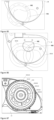
- a wall surface of the dust box 102M is provided with a first clearance surface 1024M, to increase the mounting space between the wall surface of the dust box 102M and the side wall of the device body 10, or to reserve a mounting space which allows for the mounting of the second driving structure 50M, or the first driving structure 40M, or both the first driving structure 40M and the second driving structure 50M.
- the first clearance surface 1024M may be a flat surface, an arc-shaped surface, an uneven surface, or an angular surface.
- the shape of the first clearance surface 1024M is not limited, as long as more clearance space can be provided for the mounting of the second driving structure 50M and/or the first driving structure 40M.
- the first clearance surface 1024M may be provided on the side wall of the dust box 102M, or on a bottom wall of the dust box 102M, or on a top wall of the dust box 102M, or at the connection between the top and the side wall of the dust box 102M, or at the connection between the side wall and bottom wall of the dust box 102M. Further preferably, in this implementation, when the cleaning assembly 20 is in the inwardly retracted position, the edge of the cleaning assembly 20 is within the range of the edge of the device body 10, or at least a part of the cleaning assembly 20 is located outside the peripheral side of the device body 10.
- a part of the cleaning assembly 20 is located outside the peripheral side of the device body 10, or at least a part of the edge of the cleaning assembly 20 extends beyond an edge of a travel range of the device body 10.
- the fan 103M of the dry cleaning module 100M is located between the non-swingable wet cleaning module 2001M and the swingable wet cleaning module 2002M, and the air discharge port 1022M of the dust box 102M is arranged on a wall surface facing one end of the fan 103M.
- the dust inlet 1021M of the dust box 102M is arranged on a wall surface of the dust box 102M on the side away from the fan 103M, and the air discharge port 1022M is provided with a filter assembly 1023M.
- the filter assembly 1023M is a HEPA filter, or other filter meshes.
- one end of the filter assembly 1023M may be fixed to the first clearance surface 1024M.
- the second driving structure 50M is distributed in a region defined by the wet cleaning module 200M and the first clearance surface 1024M and the fan 103M, so that the wet cleaning module 200M and the second driving structure 50M in the mounting cavity are distributed more compactly.
- the first driving structure 40M for driving the cleaning assembly 20 to rotate includes a first motor 203M and a first transmission mechanism 201M arranged on an output shaft of the first motor 203M; and the second driving structure 50M includes a second motor 204M, and a second transmission mechanism 202M arranged on an output shaft of the second motor 204M.
- the first transmission mechanism 201M is connected to the second transmission mechanism 202M via a swing arm.
- the swing arm is used to drive the entire first transmission mechanism 201M to swing, and the first motor 203M, the first transmission mechanism 201M, the fan 103M and the first clearance surface 1024M define a region for distribution of the second motor 204M and the second transmission mechanism 202M.
- the cleaning device When the garbage in the dust box 102M of the cleaning device needs to be discharged, the cleaning device generally returns to the base station, and a dust collection fan at the base station collects the garbage from the dust box 102M into the dust bin or a dust bag of the base station by blowing and sucking.
- the dust box 102M is provided with an air inlet 1028M and a dust discharge port 1027M, a blowing end of the dust collection fan at the base station is in communication with the air inlet 1028M, and an air suction end of the dust collection fan is in communication with the dust discharge port 1027M.
- the air inlet 1028M and the dust discharge port 1027M are each provided with a normally closed valve.
- the normally closed valves on the air inlet 1028M and the dust discharge port 1027M are opened.
- the normally closed valve may be actively opened by a driving structure, or may be opened by an air flow generated when the dust collection fan is opened.
- the dust discharge port 1027M is provided with a dust discharge duct 1026M for connection to the air suction end of the dust collection fan of the base station
- the air inlet 1028M may be or may not be provided with an air intake passage for connection to the blowing end of the dust collection fan at the base station
- the dust discharge duct 1026M needs to allow the garbage in the dust box 102M to flow therethrough. Therefore, the dust discharge duct 1026M is larger in size than the air intake passage.
- the swingable wet cleaning module 2002M is arranged near the first clearance surface 1024M, the air inlet 1028M is arranged on the first clearance surface 1024M, the dust discharge port 1027M is arranged on the wall surface of the dust box 102M away from the first clearance surface 1024M, and the air inlet 1028M and the dust discharge port 1027M are distributed on two sides of the air discharge port 1022M, to provide a mounting space for the dust discharge duct 1026M.
- the non-swingable wet cleaning module 2001M is preferably located between the dust discharge duct 1026M and the fan 103M of the dry cleaning module 100M.
- the dust box 102M is provided with a second clearance surface 1025M to reserve a mounting space.
- the area of the first clearance surface 1024M is greater than the area of the second clearance surface 1025M.
- the area of the first clearance surface 1024M is less than or equal to the area of the second clearance surface 1025M.
- the second clearance surface 1025M may be provided on the side wall of the dust box 102M, or on the bottom wall, or on the top wall, or at the connection between the side wall and the top wall, or at the connection between the side wall and the bottom wall.
- the second clearance surface 1025M may be a flat surface, an arc-shaped surface, an uneven surface, or an angular surface.
- the shape of the second clearance surface 1025M is not limited, as long as more clearance space can be provided for the mounting of other structures.
- other structures are possible.
- the second driving structure for driving this wet cleaning module and/or the second driving structure can be provided in the clearance space of the second clearance surface, to provide a swing space for this wet cleaning module.
- first clearance surface 1024M and the second clearance surface 1025M may be distributed adjacent to each other, may be distributed opposite to each other, or may be otherwise distributed.
- the dust discharge port 1027M is arranged on the second clearance surface 1025M.
- the dust discharge port 1027M is not arranged on the second clearance surface 1025M.
- the cleaning device is provided with two wet cleaning modules 200M, a second driving structure 50M and/or a first driving structure 40M for one of the wet cleaning modules 200M is provided in a reserved clearance space of the first clearance surface 1024M, and the other wet cleaning module 200M is provided in a reserved clearance space of the second clearance surface 1025M.
- the second driving structure 50M and/or the first driving structure 40M of the other swingable wet cleaning module 2002M may be mounted between the second clearance surface 1025M and the device body 10.
- structures other than the wet cleaning module 200M may be mounted between the second clearance surface 1025M and the device body 10.
- the cleaning device adopts a left edgewise cleaning mode
- the wet cleaning module 200M correspondingly located on the left side of the device body 10 can swing relative to the device body 10
- the wet cleaning module 200M located on the right side of the device body 10 cannot swing relative to the device body 10.
- the arrangement of the two wet cleaning modules 200M and the dust box 102M, the fan 103M and the dust discharge duct 1026M is the same as the above-mentioned implementation, and will not be described in detail here.
- both wet cleaning modules 200M correspondingly can swing relative to the device body 10, and the arrangement of each wet cleaning module 200M can adopt the arrangement of the swingable cleaning module described above, the fan 103M of the dry cleaning module 100M may be between the two wet cleaning modules 200M, and the dust discharge duct 1026M is closer to the dust inlet 1021M than the air discharge port 1022M, so that more space is reserved for the mounting of the wet cleaning module 200M.
- the wet cleaning modules 200M and the dust box 102M, the fan 103M, the dust discharge duct 1026M may be arranged in other manners than the manner described above, as long as a swinging or movement space is reserved for the swingable wet cleaning module 2002M.
- the swingable wet cleaning module 2002M swings when the cleaning device needs to perform an edgewise cleaning, such that the cleaning assembly 20 is in the outwardly swung position, and a gap is created between the cleaning member 91H of the swingable wet cleaning module 2002M and the cleaning member 91H of the non-swingable wet cleaning module 2001M. This gap will result in an uncleaned region when the cleaning device performs the edgewise cleaning.
- both wet cleaning modules on the cleaning device are configured to be swingable relative to the device body 10 and capable of swinging toward the same side of the device body 10, so that when the cleaning device moves edgewise or does not move edgewise, there is no gap between the two cleaning members 91H of the two wet cleaning modules 200M, thus avoiding the uncleaned region.
- the cleaning member is a cleaning cloth, which has a certain deformation, adjacent ends of the two adjacent cleaning clothes are pressed against each other, to eliminate the gap between the two cleaning clothes.
- both wet cleaning modules 200M are swung outwardly toward the right side of the device body 10, and there is no gap between the two cleanings.
- both wet cleaning modules 200M are retracted inwardly toward the device body 10, and there is no gap between the two cleaning members 91H.
- the two wet cleaning modules 200M swing toward the same side, and may swing synchronously or simultaneously, or asynchronously or staggeredly, as long as there is no gap between the two cleaning members 91H.
- the swing of the two wet cleaning modules 200M may be driven by a common second driving structure 50M, or may be each driven by a separately provided second driving structure 50M. In this case, only a space needs to be reserved on the device body 10 for enabling the second driving structure 50M and the two wet cleaning modules 200M to swing toward the same side.
- the bottom of the device body 10 is provided with a recessed cavity for receiving the travel component.
- the travel system 300M is swingably arranged on the device body 10, and the travel component is located in the recessed cavity.
- the travel component may float to extend outside the recessed cavity.
- the travel component is pressed inwardly toward the recessed cavity, and the travel component partially extends into the recessed cavity.
- an arc-shaped trajectory line of the swinging of the travel component does not interfere with a swing trajectory of the cleaning disk 90H of the swingable cleaning assembly 20 when the travel component abuts against the floor or the surface of the object, so that the swinging of the cleaning assembly 20 can be prevented from interfering with the movement of the travel component of the travel system 300M.
- the cleaning member is a cleaning cloth, which has a certain deformation
- the travel component when the device body 10 is raised, the travel component is in a floating state, the cleaning device is in an inoperative state
- the arc-shaped trajectory line of the swinging of the travel component may not interfere with the cleaning disk 90H of the swingable cleaning assembly 20, but may interfere with the cleaning cloth by a certain amount.
- the amount of interference is 0.1 mm, 1 mm, 2 mm, 3 mm, 4 mm, etc.
- the device body 10 of the cleaning device may also be in a travel stopping state, and travel after the cleaning assembly 20 is swung outwardly or retracted inwardly in place. For example, when the cleaning device is about to move edgewise, the cleaning assembly 20 is first swung outwardly in place and the device body 10 of the cleaning device then begins to travel edgewise, so that the outwardly swung cleaning member 91H can start cleaning from an edgewise starting position.
- the control system may control the cleaning disk 90H to rotate at a reduced speed during the outward swinging of the cleaning device, to prevent the device body 10 from being deviated from the original travel trajectory due to that the cleaning disk 90H, which swings outwardly and abuts against the obstacle, is subjected to an abutting force from the obstacle when the cleaning disk 90H rotates at a too high linear speed. That is, when the cleaning disk 90H rotates at a too high linear speed and is subjected to the abutting force from the obstacle, this abutting force is likely to push the device body 10 in the reverse direction and make same deviated. Therefore, it is preferable to reduce the rotational speed of the cleaning disk 90H when the cleaning assembly 20 swings outwardly.
- the cleaning members 91H of the two wet cleaning modules 200M have different rotational directions, which have different effects on the outward swinging and inward retraction of the cleaning members 91H.
- two adjacent cleaning members have first sides adjacent to each other and second sides away from each other. If both cleaning members 91H rotate toward the outside (from the adjacent first sides toward the second sides), the cleaning members 91H are in contact with the floor and each subjected to a friction force F.
- the friction forces applied to the cleaning disk 90H can be simplified to forces on a first end and a second end in the width direction of the device body.
- both cleaning members 91H rotate toward the inside (from the second sides toward the first sides), the cleaning members 91H are in contact with the floor and each subjected to a friction force F.
- the friction forces applied to the cleaning disk 90H can be simplified to radial forces on a first end and a second end in the width direction of the device body.
- the cleaning disks 90H of the two cleaning assemblies 20 can be controlled to rotate toward the outside to reduce the driving force for outward swinging.
- the cleaning disks 90H of the two cleaning assemblies 20 are controlled to rotate toward the inside to reduce the driving force for inward swinging. That is, the wet cleaning module 200M is driven to swing outwardly and retract inwardly by the second driving structure 50M and by controlling the steering of the cleaning disks 90H during swinging.
- no second driving structure 50M is provided for swinging the wet cleaning module 200M, and the outward swinging driving force and the inward retraction driving force are generated by controlling the steering of the two cleaning disks 90H.
- the first driving structure 40M is controlled to drive both cleaning assemblies 20 to rotate toward the outside to drive the cleaning assemblies 20 to swing outwardly.
- the first driving structure 40M is controlled to drive both cleaning assemblies 20 to rotate toward the inside to drive the cleaning assemblies 20 to retract inwardly.
- the cleaning device often needs to return to the base station for charging, collecting the garbage from the dust box 102M into the base station, washing the cleaning member 91H, removing the cleaning assembly 20 or the cleaning member 91H, and replenishing the water tank in the device body 10 with water, so that the wet cleaning module 200M of the cleaning device needs to be in the inwardly retracted position before the cleaning device returns to the base station.
- the position of the cleaning assembly 20 may be detected before the cleaning device returns to the base station. If the cleaning assembly 20 is not in the inwardly retracted position, the control system controls the second driving structure 50M to activate, so as to drive the cleaning assembly 20 to retract inwardly until reaching the inwardly retracted position.
- the control system controls the second driving structure 50M to drive the cleaning assembly 20 to forcibly retract inwardly, and whether the cleaning assembly 20 is in the inwardly retracted position is then detected. If the cleaning assembly 20 is in the inwardly retracted position, the motor of the second driving structure 50M is stalled; otherwise the motor of the second driving structure 50M continues to rotate until the cleaning assembly 20 is in the inwardly retracted position.
- the cleaning assembly 20 When the cleaning device is in other scenarios than the cleaning device returning to the base station as described above, such as a non-edgewise cleaning mode, cleaning cloth raising, and removal of the cleaning member 91H (removal of the cleaning member 91H without the need for returning to the base station), the cleaning assembly 20 needs to be in the inwardly retracted position.
- the control system may control the activation of the second driving structure 50M at an interval of a first preset time period t1 to force the drive cleaning assembly 20 to retract inwardly to remain in the inwardly retracted position.
- the control system may control the activation of the second driving structure 50M at an interval of a second preset time period t2 to force the drive cleaning assembly 20 to swing outwardly to remain in the outwardly swung position.
- the first preset time period t1 and the second preset time period t2 may be the same or different, and the first set time period and the second set time period may each be a period of any minutes.
- the first set time period and the second set time period may each be 3 minutes, 5 minutes, 10 minutes, etc.
- the cleaning assembly 20 is arranged on the device body 10 by means of a swing rod mechanism including a first swing rod and a second swing rod.
- the first swing rod is rotatably arranged on the device body 10, and the second swing rod is hingedly or rotatably connected to the first swing rod.
- the second swing rod is connected to the cleaning assembly 20, or to the first driving structure 40M that drives the cleaning assembly 20 to rotate.
- An outward swing distance of the cleaning assembly 20 is adjusted by controlling swing angles of the swing rods.
- the second driving structure 50M is configured to drive the first swing rod to swing, the first swing rod drives the entire cleaning assembly to swing outwardly or retract inwardly by means of the second swing rod, and the cleaning assembly can elastically retract when extending outwardly and encountering an obstacle.
- One swing rod mechanism may drive one cleaning assembly 20, or may drive a plurality of cleaning assemblies.
- the device body 10 includes a first part 110M and a second part 120M.
- the first part 110M may be located in front of or behind the second part 120M in the forward direction of the device body. The two arrangements are the same.
- the first part 110M is located in front of the second part 120M.
- the cleaning assembly 20 is arranged on the second part 120M, and when the cleaning assembly 20 needs to swing outwardly, the second driving structure 50M drives a module formed by the second part 120M and the cleaning assembly 20 to swing as a whole toward the outside of the device body 10 to reach the outwardly swung position.
- the second driving structure 50M drives the module formed by the second part 120M and the cleaning assembly 20 to swing as a whole toward the inside of the device body 10 to reach the inwardly retracted position.
- a clearance area is provided behind the first part 110M, and when the cleaning assembly 20 is in the inwardly retracted position, the cleaning assembly 20 and the second part 120M may be retracted into the clearance area.
- the first part 110M and the second part 120M form a complete circle, or a D-shape, or other polygons, so that the cleaning device forms a circular device, a D-shaped device, or a polygonal device.
- the second part 120M may be located on the inside of an edge of a maximum width portion of the first part 110M (width perpendicular to the forward direction of the cleaning device), or on the outside of the edge of the maximum width portion of the first part 110M.
- no clearance area is provided behind the first part 110M, and the second part 120M is located behind the entire first part 110M.
- the second driving structure 50M is provided with an elastic member, the cleaning assembly 20 or the second part 120M can elastically extend and elastically retract when being acted upon by the obstacle.
- One of the cleaning assemblies 20 of the two wet cleaning modules 200M can swing outwardly and retract inwardly, and the other thereof cannot swing outwardly.
- both cleaning assemblies 20 (main cleaning assemblies) cannot swing outwardly or can swing.
- at least one auxiliary cleaning assembly which can swing outwardly and retract inwardly is further provided on the device body 10. The auxiliary cleaning assembly swings outwardly to the outwardly swung position when performing the edgewise cleaning. When the auxiliary cleaning assembly needs to retract inwardly, the auxiliary cleaning assembly retracts inwardly to the inwardly retracted position.
- the swinging of the auxiliary cleaning assembly may be driven by the second driving structure 50M as described above, or the swinging or rotation on its own axis of the auxiliary cleaning assembly may be driven by means of belt transmission.
- the auxiliary cleaning assembly is provided with an elastic member and retracts inwardly or swings outwardly under the action of the elastic member.
- the auxiliary cleaning assembly can automatically retract and swing when encountering the obstacle.
- the cleaning device is provided with at least two wet cleaning modules 200M, two wet cleaning modules 200M of which can swing outwardly and retract inwardly.
- the cleaning assemblies 20 of the two wet cleaning modules 200M can be folded or completely overlap so that the cleaning assemblies 20 are within the range of the device body 10.
- the two cleaning assemblies 20 are staggered in height by the raising and lowering action of the lifting structure.
- the cleaning assemblies 20 then retract inwardly such that the inner sides of the cleaning assemblies 20 completely or partially overlap in a thickness direction of the device body 10, so that the two cleaning assemblies 20 can be within the range of the device body 10.
- the cleaning assembly 20 swings outwardly and is then lowered such that the cleaning assembly 20 is in the outwardly swung position.
- the travel component is located between the main brush 101M of the dry cleaning module 100M and the cleaning assembly 20.
- one of the two cleaning assemblies 20 can swing outwardly and retract inwardly, and the other thereof cannot swing outwardly and retract inwardly; or both cleaning assemblies 20 can swing outwardly and retract inwardly.
- the device body 10 of the cleaning device is a specially-shaped device. As shown in FIG. 115 , the device body 10 has a body and a protruding portion 130M protruding outwardly from the body. At least one wet cleaning module 200M is provided on the protruding portion 130M, and the cleaning assembly 20 of this wet cleaning module 200M can swing outwardly and retract inwardly. The arrangement of the protruding portion 130M and the outward swinging of the cleaning assembly 20 cooperate to further increase the outward swing distance of the cleaning assembly 20 relative to the body.
- the cleaning device is provided with two wet cleaning modules 200M, one on the protruding portion 130M and the other on the body.
- both may be arranged on the protruding portion 130M.
- the cleaning assembly 20 located on the body can or cannot swing outwardly, depending on the requirements.
- the device body 10 is shaped like a water drop.
- the device body 10 may have other irregular shapes, such as polygons and ovals.
- the polygon may be a triangle, a quadrangle, etc., with each corner of the polygon as a protruding portion 130M.
- the cleaning assembly 20 of the wet cleaning module 200M may be arranged on some protruding portion 130M
- the side brush 400M may be arranged on some protruding portion 130M
- the main brush 101M of the dry cleaning module 100M may be arranged on some protruding portion 130M.
- the cleaning assembly 20 or the side brush 400M or the main brush 101M is arranged the protruding portion 130M, and the specific arrangement is selected as needed.
- the wet cleaning module 200M may further include at least one half-fold wet cleaning mechanism.
- the half-fold wet cleaning mechanism includes a mounting cylinder and a cleaning body.
- the cleaning body includes a first cleaning portion and a second cleaning portion.
- the two cleaning portions have a folded state and an unfolded cleaning state. In the folded state, the two cleaning portions are folded in half and can be received in the mounting cylinder under the drive of a telescoping mechanism. In the unfolded state, the two cleaning portions extend from the inside of the mounting cylinder and are unfolded, where the first cleaning portion is located below the bottom of the device body 10 and the second cleaning portion extends beyond the device body. When the device body 10 is traveling, the second cleaning portion extending beyond the device body 10 can perform an edgewise cleaning.
- the two cleaning portions can press against each other to squeeze out the liquid from each other. That is, the cleaning device is provided with both the cleaning assembly 20 and the half-fold wet cleaning mechanism, both of which cooperate to further improve the cleaning effect. After the edgewise cleaning is completed, the two cleaning portions switch to the folded state. It is also possible that no mounting cylinder is provided in this implementation. In another implementation, the wet cleaning module 200M may be provided with only a half-fold wet cleaning mechanism, or with only the cleaning assembly 20 described above.
- the wet cleaning module 200M includes two cleaning assemblies 20.
- One of the cleaning assemblies 20 includes a cleaning disk 90H and a cleaning member 91H.
- the cleaning disk 90H is oscillated to drive the cleaning member 91H to oscillate, so as to clean the floor.
- the other cleaning assembly 20 includes a cleaning disk 90H and a cleaning member 91H.
- the cleaning disk 90H rotates to drive the cleaning member 91H to rotate, so as to clean the floor.
- the rotating cleaning assembly 20 can or cannot swing outwardly and retract inwardly.
- the oscillating cleaning assembly 20 can or cannot swing outwardly and retract inwardly.
- the oscillating cleaning assembly 20 and the rotating cleaning assembly 20 on the device body 10 can be distributed as long as the movements of the two do not interfere with each other, and the specific arrangement is not limited.
- the oscillating cleaning assembly 20 and the rotating cleaning assembly 20 are one behind the other in the forward direction of the cleaning device.
- the two cleaning assemblies 20 are distributed left and right in the width direction of the device body 10.
- one of the oscillating cleaning assembly 20 and the rotating cleaning assembly 20 is provided with a clearance region which allows for the mounting or distribution of the other cleaning assembly 20.
- at least one of the oscillating cleaning assembly 20 and the rotating cleaning assembly 20 can swing outwardly and retract inwardly to switch between the outwardly swung position and the inwardly retracted position.
- the cleaning assembly 20 may also be configured in a form similar to a strike plate of the front portion of the cleaning device, and when the cleaning assembly 20 encounters an obstacle, the cleaning assembly 20 is retracted inwardly by the obstacle.
- the cleaning assembly 20 remains in the outwardly swung position under the action of an elastic member. In the inwardly retracted position, at least a part of the cleaning disk 90H is located outside the peripheral side of the device body 10.
- wet cleaning modules 200M there are at least two wet cleaning modules 200M, two wet cleaning modules 200M of which share the second driving structure 50M described above, that is, one second driving structure 50M drives the two cleaning assemblies 20 to swing, or the two wet cleaning modules 200M are each provided with one second driving structure 50M.
- the cleaning device is provided with one cleaning assembly 20 for cleaning a surface to be cleaned. During edgewise cleaning, the cleaning assembly 20 swings outwardly. When the cleaning assembly 20 needs to retract inwardly, the cleaning assembly 20 retracts inwardly. If the cleaning device is provided with only one cleaning assembly 20, the cleaning assembly 20 may also remain in the outwardly swung position at all times, without the need for the cleaning assembly 20 to switch between the outwardly swung position and the inwardly retracted position.
- the cleaning assembly 20 may be an oscillating cleaning assembly 20 or a rotating cleaning assembly 20 as described above, or a mopping roller brush.
- the wet cleaning module 200M may be replaced with a side brush to enable the outward swinging and inward retraction of the side brush 400M, improving the edgewise cleaning function of the side brush 400M.
- the wet cleaning module may be replaced with a main brush to enable the outward swinging and inward retraction of the main brush and increase the cleaning area of the main brush.
- the side brush 400M can swing outwardly and retract inwardly relative to the device body 10 by means of the driving structure described above, and the side brush 400M has an outwardly swung position and an inwardly retracted position.
- the side brush 400M swings outwardly, the side brush 400M extends beyond the device body 10 to reach the outwardly swung position.
- the side brush 400M retracts inwardly and swings to the inwardly retracted position, the side brush 400M may be within the range of the device body 10, or may be partially located outside the peripheral side of the device body 10.
- the side brush 400M When the side brush 400M is in the outwardly swung position, the side brush 400M has a better edgewise effect on the obstacle.
- a plurality of side brushes 400M may be provided.
- the plurality of side brushes 400M are distributed spaced apart from each other on the outside of the edge of the device body 10, the side brushes 400M are distributed on the device body 10 and keep clear of the wet cleaning module 200M, and the side brushes 400M can or cannot swing outwardly.
- a cleaning device having a cleaning assembly 20 is mainly described in Embodiments 1-8.
- the cleaning assembly 20 can switch between a first position and a second position, to better achieve a cleaning effect.
- a first driving structure 40M includes at least a rotation driving member 230 and a transmission assembly 240 in this embodiment
- a second driving structure 50M includes at least a guide assembly 50 and a drive mating structure 711 in this embodiment.
- This embodiment provides a cleaning device, as shown in FIGS. 1 to 6 , including a device body 10 and a cleaning assembly 20.
- the cleaning assembly 20 is connected to the device body 10, and the cleaning assembly 20 has a first position. When the cleaning assembly 20 is in the first position, a part of the cleaning assembly 20 is located outside a peripheral side of the device body 10.
- the cleaning assembly 20 protruding outside the device body 10 can come into contact with an edge of an obstacle during the movement of the device body 10, so as to clean a region near the obstacle.
- Embodiment 2 provides a cleaning device, as shown in FIGS. 1 to 6 , including a device body 10 and a cleaning assembly 20.
- the cleaning assembly 20 is movably connected to the device body 10, and the cleaning assembly 20 has a first position and a second position.
- a part of the cleaning assembly 20 is located outside a peripheral side of the device body 10.
- the part of the cleaning assembly 20 that is located outside the peripheral side of the device body 10 when the cleaning assembly 20 is moved to the second position is larger than the part of the cleaning assembly 20 that is located outside the peripheral side of the device body 10 when the cleaning assembly 20 is in the first position.
- the part of the cleaning assembly 20 that is located outside the peripheral side of the device body 10 is in contact with the edge of the obstacle.
- the cleaning assembly 20 has a first position and a second position during cleaning of a surface to be cleaned by the cleaning assembly 20, where the cleaning assembly 20 moves in a direction away from the device body 10 when switching from the first position to the second position, the part of the cleaning assembly 20 that is located outside the device body 10 when the cleaning assembly 20 is in the second position is in contact with the edge of the obstacle, to achieve cleaning of a region near the obstacle.
- the cleaning assembly 20 when the cleaning assembly 20 is in the first position and in the second position, the cleaning assembly 20 is at least partially located outside the peripheral side of the device body 10, and when in the second position, cleaning is achieved at a blind spot such as the obstacle, the cleaning is more comprehensive, and the cleaning efficiency is improved.
- the obstacle may be a wall, a piece of furniture and other structures.
- the cleaning device when the cleaning device moves to a corner of the wall, the cleaning device senses an obstacle, in which case the cleaning assembly 20 is driven to switch from the first position to the second position, so that the cleaning assembly 20 moves toward the obstacle and comes into contact with an edge of the obstacle to clean a region at the corner of the wall.
- the cleaning device may sense the obstacle in different ways.
- an infrared sensor implements detection by using light reflection, but of course the other ways are possible, as long as the position of the obstacle can be identified.
- a distance between the part of the cleaning assembly 20 that is located outside the peripheral side of the device body 10 and the edge of the obstacle is less than or equal to a threshold, which is greater than or equal to 0.
- the cleaning assembly 20 includes a cleaning disk 90H and a cleaning member 91H arranged on the cleaning disk 90H.
- a gap is reserved between the cleaning disk 90H and the edge of the obstacle at all times when the cleaning device performs an edgewise cleaning, preventing the cleaning disk 90H from hitting the edge of the obstacle.
- the cleaning member 91H may be in contact with the edge of the obstacle or have a reserved spacing from the edge of the obstacle.
- the cleaning cloth when the cleaning member 91H is selected as a cleaning cloth, the cleaning cloth has a certain deformation, so that during the edgewise cleaning, the cleaning cloth may be in contact with the edge of the obstacle; or not in contact with the edge of the obstacle. Therefore, by setting the threshold to be greater than or equal to 0, when the threshold is 0, the cleaning member 91H is in contact with the edge of the obstacle; and when the threshold is greater than 0, the cleaning member is not in contact with the edge of the obstacle.
- the threshold may be 1 mm, 2 mm, 3 mm, 4 mm, 5 mm, 1 cm, 1.5 cm, etc.
- the cleaning member 91H is a cleaning cloth
- the line of travel of the widest position of the device body 10 determines the maximum cleaning range of the cleaning device, and when the cleaning assembly 20 moves to the second position, at least a part of the edge of the cleaning assembly 20 reaches the edge of the maximum cleaning range.
- the device body 10 has a wide part and a narrow part, and the cleaning assembly 20 is mounted in a region outside the widest position of the device body 10, so that although a part of the cleaning assembly 20 extends to a region outside the device body 10, the edge of the cleaning assembly 20 is still flush with a boundary of a wide region in the travel direction.
- the cleaning assembly 20 is mounted at a front end or rear end of the device body 10 in the travel direction of the cleaning device, the width of the front end or rear end being less than the width of a middle region of the device body 10. After the cleaning assembly 20 moves toward the second position away from the device body 10, the part outside the device body 10 is flush with a region boundary of the middle region of the device body 10 in the travel direction.
- the line of travel of the widest position of the device body 10 determines the maximum cleaning range of the cleaning device, and when the cleaning assembly 20 moves to the second position, at least a part of the edge of the cleaning assembly 20 extends beyond the outer side of the maximum cleaning range.
- the device body 10 has a wide part and a narrow part, and the cleaning assembly 20 is mounted in a region outside the widest position of the device body 10, so that although a part of the cleaning assembly 20 extends to a region outside the device body 10, the edge of the cleaning assembly 20 may extend outside a wide partial region in the travel direction.
- the cleaning assembly 20 is mounted at a front end or rear end of the device body 10 in the travel direction of the cleaning device, the width of the front end or rear end being less than the width of a middle region of the device body 10. After the cleaning assembly 20 moves toward the second position away from the device body 10, the part outside the device body 10 extends outside the wide partial region.
- the cleaning device further includes a driving assembly.
- the driving assembly is in drive connection with the cleaning assembly 20 to move the cleaning assembly 20 between the first position and the second position.
- the driving assembly includes a guide assembly 50 and a drive mating structure 711.
- the drive mating structure 711 is movably connected to the guide assembly 50, and one of the drive mating structure 711 and the guide assembly 50 is connected to the cleaning assembly 20, such that when guide assembly 50 moves relative to drive mating structure 711, the cleaning assembly 20 moves between the first position and the second position.
- the driving assembly is provided with the guide assembly 50 for guiding the cleaning assembly 20, and the drive mating structure 711 for switching the cleaning assembly 20 between the first position and the second position. At least one of the drive mating structure 711 and the guide assembly 50 is pivotally moved to drive or cause the cleaning assembly 20 to move by means of pivotal movement.
- the guide assembly 50 extends in a first direction in the form of a straight line, and when the drive mating structure 711 moves relative to the guide assembly 50, the drive mating structure 711 can move in the first direction.
- the drive mating structure 711 is in drive connection with the guide assembly 50 by means of a threaded rod mating with a threaded sleeve 220, the threaded rod being in threaded connection with the threaded sleeve 220, so that by means of the threaded connection between the threaded rod and the threaded sleeve 220, the rotation of one of the threaded rod and the threaded sleeve 220 drives the other to move in the first direction.
- the use of the thread and the threaded sleeve 220 provides a limiting function while providing a drive connection, so as to limit the direction of movement of the cleaning assembly 20. That is, the translation of the cleaning assembly 20 is achieved by means of the threaded rod and the threaded sleeve 220.
- the guide assembly 50 includes the threaded rod which is in drive connection with the drive mating structure 711, and the drive mating structure 711 includes the threaded sleeve 220.
- the threaded rod is in threaded connection with the threaded sleeve 220, and the drive mating structure 711 is connected to the cleaning assembly 20 to move the cleaning assembly 20 by means of the drive mating structure 711.
- the device body 10 is provided with a drive motor 710.
- the drive motor 710 drives the threaded rod to rotate, so as to drive the threaded sleeve 220 on the threaded rod to move in the direction of extension of the threaded rod, i.e. in the first direction, by means of the rotation of the threaded rod on its own axis.
- the threaded sleeve 220 when moved, will drive the cleaning assembly 20 to move, so as to translate the cleaning assembly 20 in the first direction.
- the cleaning assembly 20 switches between the first position and the second position by the forward and reverse rotation of the drive motor 710.
- the structural form of the connection between the drive mating structure 711 and the cleaning assembly 20 is not limited, and it is also possible that the drive mating structure 711 is formed on the cleaning assembly 20, and the drive mating structure 711 has a thread for mating with the threaded rod.
- the cleaning assembly 20 has a through hole in which a linear bearing is mounted, and the cleaning device further includes a guide rod 530.
- the guide rod 530 is arranged on the device body 10, and the linear bearing is sleeved on the guide rod 530.
- the guide rod 530 provides a guiding function and the linear bearing is arranged at the through hole of the cleaning assembly 20, so that the cleaning assembly 20 can slide in the direction of extension of the guide rod 530 by means of the linear bearing.
- the guide rod 530 extends in the first direction.
- One or more guide rods 530 are provided. When a plurality of guide rods 530 are provided, the plurality of guide rods 530 each extend in the first direction, and the plurality of guide rods 530 are symmetrically arranged with respect to the threaded rod, to facilitate the smooth mounting and movement of the cleaning assembly 20.
- the cleaning device further includes a first stop plate 410 and a second stop plate 420.
- the first stop plate 410 and the second stop plate 420 are spaced apart from each other along the direction of a connecting line between the first position and the second position.
- a mounting region 430 is formed between the first stop plate 410 and the second stop plate 420, and a part of the cleaning assembly 20 is accommodated inside the mounting region 430.
- the cleaning assembly 20 is located inside the mounting region 430 and moves inside the mounting region 430, and the two stop plates provide a limiting function, to prevent the cleaning assembly 20 from being disengaged from the device body 10.
- two ends of the threaded rod are rotatably mounted to the first stop plate 410 and the second stop plate 420 by means of bearings, and two ends of the guide rod 530 are also mounted to the first stop plate 410 and the second stop plate 420.
- the movement channel 300H includes an elongated hole 110 or an arc-shaped hole 110R.
- the device body 10 inside the mounting region 430, the device body 10 is provided with an elongated hole 110.
- the elongated hole 110 extends along the direction of the connecting line between the first position and the second position.
- a part of the cleaning assembly 20 extends through the elongated hole 110 outside the device body 10, and when the cleaning assembly 20 switches between the first position and the second position, a part of the cleaning assembly 20 moves in the elongated hole 110.
- the cleaning assembly 20 switches between the first position and the second position, a part of the cleaning assembly 20 moves in the elongated hole 110 to achieve a limiting effect on the cleaning assembly 20, ensuring that the cleaning assembly 20 can move stably without deviation.
- the cleaning device further includes a sealing structural member which shields the elongated hole 110.
- a peripheral edge of the sealing structural member is connected to the device body 10, and the sealing structural member has a mounting opening.
- the mounting opening is within the range of the region of the elongated hole 110, a part of the cleaning assembly 20 passes through the mounting opening, and a peripheral edge of the mounting opening is connected to a part of the cleaning assembly 20.
- the peripheral edge of the sealing structural member is connected to the device body 10 and the peripheral edge of the mounting opening is connected to the cleaning assembly 20 to shield the elongated hole 110 without affecting the movement of the cleaning assembly 20.
- the cleaning assembly 20 drives the sealing structural member to move so that the mounting opening moves along with the cleaning assembly 20 to maintain a sealed condition at all times, thereby preventing dust and the like from entering the interior of the device body 10 through the elongated hole 110.
- the sealing structural member is a rubber-coated layer 820H or rubber.
- the rubber-coated layer 820H has one end fixed to the device body 10 and the other end fixed to an outer periphery of the mounting opening or the mounting portion.
- the rubber-coated layer 820H has a certain elasticity, and the cleaning assembly 20, during swinging, drives the end of the rubber-coated layer 820H fixed to the mounting opening or the mounting portion to swing, and the rubber-coated layer 820H is deformed to seal the elongated hole 110 or the arc-shaped hole 110R.
- the sealing structural member is made of elastic rubber.
- the cleaning assembly 20 includes a housing 210, a transmission assembly 240, a rotation driving member 230, and a movable cleaning member 250.
- the housing 210 has an accommodating cavity, in which a part of the transmission assembly 240 is accommodated.
- the rotation driving member 230 is accommodated on the housing 210, and the rotation driving member 230 is connected to the transmission assembly 240.
- the movable cleaning member 250 is arranged outside the accommodating cavity, another part of the transmission assembly 240 extends beyond the accommodating cavity and is in drive connection with the movable cleaning member 250, and the rotation driving member 230 drives the movable cleaning member 250 to rotate by means of the transmission assembly 240.
- the rotation driving member 230 provides a driving force for rotating the cleaning assembly 20 on its own axis. Under the driving action of the rotation driving member 230, the cleaning assembly 20 rotates on its own axis and can clean a surface to be cleaned.
- the transmission assembly 240 is arranged between the rotation driving member 230 and the movable cleaning member 250, so as to regulate the rotational speed of the movable cleaning member 250 by means of the transmission assembly 240 to improve the cleaning efficiency.
- the transmission assembly 240 includes: an input transmission member accommodated inside the accommodating cavity, the rotation driving member 230 being in drive connection with the input transmission member; an output transmission member accommodated inside the accommodating cavity, the input transmission member being in drive connection with the output transmission member; and a transmission shaft, the output transmission member being in drive connection with a first end of the transmission shaft, and a second end of the transmission shaft extending beyond the accommodating cavity and being in drive connection with the movable cleaning member 250.
- the input transmission member and the output transmission member may each be a structural member having a transmission function, and the transmission shaft is arranged to transmit a rotation force of the output transmission member to the movable cleaning member 250, so as to rotate the movable cleaning member 250.
- the input transmission member includes a first transmission gear 241 and a second transmission gear 242 which are arranged coaxially and rotate synchronously.
- the rotation driving member 230 is in drive connection with the first transmission gear 241, and the tooth diameter and the number of teeth of the first transmission gear 241 are greater than the tooth diameter and the number of teeth of the second transmission gear 242.
- the output transmission member includes a third transmission gear 243.
- the third transmission gear 243 meshes with the second transmission gear 242, the third transmission gear 243 is in drive connection with the transmission shaft, and the tooth diameter and the number of teeth of the third transmission gear 243 are greater than the tooth diameter and the number of teeth of the second transmission gear 242, so that there is a gear ratio between the second transmission gear 242 and the third transmission gear 243.
- the first transmission gear 241 and the second transmission gear 242 rotate synchronously and coaxially, and the number of teeth tooth diameter and the number of teeth of the first gear in drive connection with the rotation driving member 230 are greater than the tooth diameter and the number of teeth of the second transmission gear 242. Therefore, a good speed reduction effect is provided when the second gear meshes with the third gear, to prevent the movable cleaning member 250 from rotating too quickly, which otherwise causes unstable mounting.
- first transmission gear 241, the second transmission gear 242 or the third transmission gear 243 can be adaptively changed as needed, to guarantee a preset gear ratio and the rotational speed of the movable cleaning member 250.
- two pulleys of different sizes may also be provided between the input transmission member and the output transmission member, and power transfer between the two pulleys is implemented by means of a belt.
- the output transmission member including the third transmission gear 243
- the output transmission member may include a plurality of other gears, that is, the number of gears can be adaptively increased or decreased as needed.
- the cleaning assembly 20 further includes a micro-switch 60 and a controller.
- the micro-switch 60 is arranged on the device body 10, and the micro-switch 60 is configured to detect the position of the movable cleaning member 250.
- the controller is mounted on the device body 10, and the controller is electrically connected to the micro-switch 60, the rotation driving member 230, and the drive mating structure 711 of the cleaning device.
- the micro-switch 60 is arranged on the device body 10, and the cleaning assembly 20 is in contact with the micro-switch 60 in both the first position and the second position to trigger the micro-switch 60.
- the triggered micro-switch 60 sends a signal to the controller to cause the controller to control the operations of the rotation driving member 230 and the drive mating structure 711, so that the position of the cleaning assembly 20 can be controlled by controlling the forward and reverse rotation of the drive motor 710, and the state of the movable cleaning member 250 can also be controlled by controlling the activation and deactivation of the rotation driving member 230.
- the cleaning device further includes a static driving member 320 and a static cleaning member 310.
- the static driving member 320 is mounted on the device body 10, the static driving member 320 is in drive connection with the static cleaning member 310, and the static cleaning member 310 is rotatably connected to the device body 10.
- the static cleaning member 310 is driven by the static driving member 320 such that the static cleaning member 310 rotates on its own axis to clean the surface to be cleaned. Moreover, the static cleaning member 310 cooperates with the cleaning assembly 20, the static cleaning member 310 is stationary relative to the device body 10, and the use of a one-movable-one-static solution facilitates the enhancement of the cleaning efficiency and avoids the phenomenon of incomplete cleaning due to blind spots during cleaning.
- the movable cleaning member 250 and the static cleaning member 310 both perform cleaning by means of the cooperation of a circular rotating disk and a mopping cloth.
- the shape of the rotating disk connected to the driving member may not be circular, and bristles may be provided on the rotating disk for cleaning, as long as the technical effect of performing mopping can be achieved when the movable cleaning member 250 and the static cleaning member 310 are rotating in the present application.
- Embodiment 3 This embodiment differs from Embodiment 2 in that a different sealing structural member is used in this embodiment to maintain a seal at the elongated hole 110 during the switching of the cleaning assembly 20 between the first position and the second position to prevent dust and the like from entering the interior of the device body 10 through the elongated hole 110.
- the device body 10 is provided with a track groove 120 extending in a second direction, and the cleaning device further includes a first seal member 810.
- the first seal member 810 includes a first stop portion 8101, a second stop portion 8102 and a guide protrusion.
- the first stop portion 8101 and the second stop portion 8102 are angularly arranged, and at least a part of the guide protrusion extends into the interior of the track groove 120.
- the guide protrusion rotates on its own axis and moves in the direction of extension of the track groove 120.
- the second stop portion 8102 stops a part of the elongated hole 110 when the cleaning assembly 20 is in the first position
- the first stop portion 8101 stops a different part of the elongated hole 110 when the cleaning assembly 20 is in the second position.
- the first stop portion 8101 is linked with the second stop portion 8102 such that when the cleaning assembly 20 switches between the first position and the second position and the cleaning assembly 20 is pressed against the first stop portion 8101 or the second stop portion 8102, the first stop portion 8101 and the second stop portion 8102 rotate simultaneously.
- the cleaning assembly 20 is in the first position, the cleaning assembly 20 is pressed against the first stop portion 8101 such that the second stop portion 8102 stops a part of the elongated hole 110.
- the cleaning assembly 20 switches from the first position to the second position, the cleaning assembly 20 is pressed against the second stop portion 8102 to rotate the first stop portion 8101 and the second stop portion 8102.
- the first stop portion 8101 stops a different part of the elongated hole 110.
- the position where the cleaning assembly 20 is pressed against the first stop portion 8101 changes as the cleaning assembly 20 moves due to the translation of the cleaning assembly 20, and the guide protrusion therefore needs not only rotate along with the first stop portion 8101 and the second stop portion 8102, but also needs to move in the track groove 120 in the second direction.
- first stop portion 8101 and second stop portion 8102 and the shapes of first stop portion 8101 and the second stop portion 8102 can be adaptively adjusted as needed.
- the first direction is arranged at an angle of 90° to the second direction to facilitate movement of the guide protrusion in the track groove 120 during the switching of the cleaning assembly 20 from the first position to the second position.
- the first seal member 810 is a rigid seal member to facilitate rotation under the pressing action of the cleaning assembly 20.
- the first seal member 810 may be made of stainless steel or mild steel.
- the cleaning device further includes a second seal member 820.
- the second seal member 820 is arranged between the device body 10 and the first seal member 810.
- the second seal member 820 is a flexible seal member, and the second seal member 820 may be made of rubber, silicone, etc.
- no second seal member 820 may be provided, i.e. only the first seal member 810 seals the elongated hole 110.
- Embodiment 4 This embodiment differs from Embodiment 2 in that in this embodiment, the drive mating structure 711 is in drive connection with the guide assembly 50 by means of a gear mating with a rack.
- the drive mating structure 711 includes a driving gear
- the guide assembly 50 includes a first guide member 510.
- the first guide member 510 is a linear rack with which the driving gear meshes, and the drive mating structure 711 drives the cleaning assembly 20 to move linearly.
- the cleaning assembly 20 is provided with a drive motor 710, the drive motor 710 being in drive connection with the driving gear, and the first guide member 510 is mounted on the device body 10.
- the drive motor 710 drives the gear to rotate
- the driving gear is rotatably connected to the linear gear and moves in the direction of extension of the driving rack
- the driving gear drives the cleaning assembly 20 to move, so as to enable the position movement of the cleaning assembly 20.
- the cleaning assembly 20 is driven to move by the means of the driving gear meshing with the linear rack, achieving the technical effect of position limiting while ensuring a stable connection, so that the cleaning assembly 20 moves in a straight line.
- the cleaning assembly 20 includes a guide groove 260, the guide groove 260 having a channel extending in the first direction, and the guide assembly 50 further includes a second guide member 520.
- the second guide member 520 and the first guide member 510 are arranged side by side and spaced apart from each other, at least a part of the second guide member 520 is accommodated in the channel, and the second guide member 520 is slidably connected to the guide groove 260.
- the length of the second guide member 520 is greater than the length of the first guide member 510.
- driving gear and the drive motor 710 may be mounted on the cleaning assembly 20, and the linear rack may be mounted on the device body 10.
- the drive motor 710 and the driving gear are mounted on the device body 10 and the linear rack is mounted on the cleaning assembly 20.
- Embodiment 5 This embodiment differs from Embodiment 2 in that in this embodiment, the drive mating structure 711 is in drive connection with the guide assembly 50 by means of a worm mating with a gear.
- the cleaning device further includes a locking assembly 270.
- the guide assembly 50 includes a worm with which the drive mating structure 711 is in drive connection.
- the drive mating structure 711 includes a driving gear with which the worm is in drive connection.
- a locking portion of the locking assembly 270 is locked with or unlocked from the driving gear.
- the driving gear is unlocked from the locking portion, the worm rotates and drives the driving gear to rotate on its own axis, so as to rotate the cleaning assembly 20.
- the driving gear is locked by the locking portion, the worm rotates, the driving gear is locked by the locking portion and does not rotate, so that the driving gear moves in the direction of extension of the worm and drives the cleaning assembly 20 to move in the first direction.
- the worm mates with the driving gear in such a way that the drive motor 710 drives the worm to rotate when the driving gear is unlocked from the locking portion. While the worm is rotating, teeth on the worm can mesh with the driving gear, which is rotated by a circumferential force provided by the worm, thereby driving the cleaning assembly 20 to rotate.
- the drive motor 710 drives the worm to rotate, which imparts an axial force to the driving gear at this time, so that the driving gear is moved in an axial direction of the worm and drives the cleaning assembly 20 to move.
- the drive motor 710 is mounted on the device body 10, and the drive motor 710 drives the cleaning assembly 20 to rotate on its own axis or move by means of the drive connection with the worm, and the direction of movement of the cleaning assembly 20 and the direction of rotation of the movable cleaning member 250, on its own axis, of the cleaning assembly 20 can be controlled by controlling the forward or reverse rotation of the drive motor 710.
- a gear meshing with the driving gear and the movable cleaning member 250 may be provided between the driving gear and the movable cleaning member 250, and the gear ratio is adjusted by means of meshing between the gears, to enable speed adjustment of the movable cleaning member 250.
- the locking assembly 270 is a lead screw motor.
- the lead screw motor controls a lead screw to extend toward the driving gear so as to retain the driving gear so that the driving gear cannot rotate, or the lead screw motor controls the lead screw to retract away from the driving gear so as to disengage from the driving gear.
- Embodiment 6 Different from Embodiment 2, in this embodiment, a method is provided in which the cleaning assembly 20 moves in an arc-shaped direction during switching between the first position and the second position.
- the guide assembly 50 is connected to the cleaning assembly 20, the drive mating structure 711 is arranged on the device body 10, and the drive mating structure 711 operates to drive the guide assembly 50 to move in the first direction, so that the guide assembly 50 drives the cleaning assembly 20 to move in the first direction.
- the guide assembly 50 has a guide surface that faces the drive mating structure 711.
- the guide surface is an arc-shaped surface, which extends in the first direction.
- the drive mating structure 711 drives the guide assembly 50, together with the cleaning assembly 20, to move in the direction of extension of the arc-shaped surface.
- the cleaning assembly 20 moves along the arc-shaped surface.
- the guide surface has an arc-shaped rack
- the drive mating structure 711 includes a driving gear that meshes with the arc-shaped rack.
- the device body 10 is further provided with a drive motor 710.
- the drive motor 710 drives the driving gear to rotate, and the driving gear meshes with the arc-shaped rack to drive the arc-shaped rack to move.
- the device body 10 is provided with a micro-switch 60 and a controller.
- the micro-switch 60 is configured to detect the position of the movable cleaning member 250.
- the controller is electrically connected to the micro-switch 60, the rotation driving member 230, and the drive motor 710.
- the micro-switch 60 is arranged on the device body 10, and the cleaning assembly 20 is in contact with the micro-switch 60 in both the first position and the second position to trigger the micro-switch 60.
- the triggered micro-switch 60 sends a signal to the controller to cause the controller to control the operations of the rotation driving member 230 and the drive mating structure 711, so that the position of the cleaning assembly 20 can be controlled by controlling the forward and reverse rotation of the drive motor 710, and the state of the movable cleaning member 250 can also be controlled by controlling the activation and deactivation of the rotation driving member 230.
- the micro-switch 60 and the controller it is also possible to provide a stop structure, a current sensing apparatus and a controller such that the cleaning assembly 20 cannot move further under the action of the stop structure after moving to the first position or the second position.
- the drive motor 710 cannot continue to operate, the current changes, the current sensing apparatus detects the current change and feedbacks an electrical signal to the controller, and the controller controls the drive motor 710 to adjust the rotational direction of the output shaft.
- Embodiment 7 In this embodiment, a cleaning device is provided. As shown in FIG. 20 to FIG. 23 , the cleaning device includes a device body 10, a cleaning assembly 20 and a restoring member.
- the cleaning assembly 20 is movably connected to the device body 10, and the cleaning assembly 20 has an initial position and a retracted position.
- One end of the restoring member is connected to the cleaning assembly 20, the other end of the restoring member is connected to the device body 10, and the restoring member provides a restoring force for holding the cleaning assembly 20 in the initial position.
- the cleaning assembly 20 When the cleaning assembly 20 is in the retracted position, a part of the cleaning assembly 20 is located outside a peripheral side of the device body 10.
- the part of the cleaning assembly 20 that is located outside the peripheral side of the device body 10 when the cleaning assembly 20 is in the initial position is larger than the part of the cleaning assembly 20 that is located outside the peripheral side of the device body 10 when the cleaning assembly 20 is in the retracted position, and the cleaning assembly 20 switches from the initial position toward the retracted position when the part of the cleaning assembly 20 that is located outside the peripheral side of the device body 10 abuts against an edge of an obstacle.
- the restoring member provides a restoring force for the cleaning assembly 20 to remain in the initial position, and when the cleaning assembly 20 needs to clean a corner of an obstacle, such as a wall, the cleaning assembly 20 is in contact with the obstacle, and the obstacle applies a driving force for the cleaning assembly 20 to move from the initial position to the retracted position, such that the cleaning assembly 20 may be held in the initial position, in the retracted position, or in a position between the two positions under the action of the restoring member, and in this case, the part of the cleaning assembly 20 that is located outside the device body 10 can clean the corner region of the obstacle, thereby effectively improving the cleaning efficiency.
- the elastic member is a spring.
- the line of travel of the widest position of the device body 10 determines the maximum cleaning range of the cleaning device, and when the cleaning assembly 20 is in the initial position, at least a part of the edge of the cleaning assembly 20 reaches the edge of the maximum cleaning range.
- the device body 10 has a wide part and a narrow part, and the cleaning assembly 20 is mounted in a region outside the widest position of the device body 10, so that although a part of the cleaning assembly 20 extends to a region outside the device body 10, the edge of the cleaning assembly 20 is still flush with a boundary of a wide region in the travel direction.
- the cleaning assembly 20 is mounted at a front end or rear end of the device body 10 in the travel direction of the cleaning device, the width of the front end or rear end being less than the width of a middle region of the device body 10. After the cleaning assembly 20 moves toward the initial position away from the device body 10, the part outside the device body 10 is flush with a region boundary of the middle region of the device body 10 in the travel direction.
- the line of travel of the widest position of the device body 10 determines the maximum cleaning range of the cleaning device, and when the cleaning assembly 20 is in the initial position, at least a part of the edge of the cleaning assembly 20 extends beyond the outer side of the maximum cleaning range.
- the device body 10 has a wide part and a narrow part, and the cleaning assembly 20 is mounted in a region outside the widest position of the device body 10, so that although a part of the cleaning assembly 20 extends to a region outside the device body 10, the edge of the cleaning assembly 20 may extend outside a wide partial region in the travel direction.
- the cleaning assembly 20 is mounted at a front end or rear end of the device body 10 in the travel direction of the cleaning device, the width of the front end or rear end being less than the width of a middle region of the device body 10. After the cleaning assembly 20 moves toward the initial position away from the device body 10, the part outside the device body 10 extends outside the wide partial region.
- the embodiments of the present application achieve the following technical effects.
- the cleaning assembly 20 When the cleaning assembly 20 is in the first position and in the second position, the cleaning assembly 20 is at least partially located outside the peripheral side of the device body 10, and when in the second position, cleaning is achieved at a blind spot such as the obstacle. The cleaning is more comprehensive, and the cleaning efficiency is improved.
- the cleaning assembly 20 switches between the first position and the second position by the forward and reverse rotation of the drive motor 710. The stability of the transmission relationship is improved.
- the movable cleaning assembly 20 and the static cleaning member 310 are cooperatively used, and the combined cleaning in a movable manner and a static manner improves the cleaning efficiency of the cleaning device.
- Embodiments 2 to 7 are also not limited to being combined with the aforementioned Embodiment 1, and on the basis of feasibility, the overall or partial structure of Embodiments 2 to 7 can be combined with any feasible embodiment to meet different purposes of use, which is not specially limited herein.
- Embodiment 8 This embodiment provides a cleaning device, including a device body 10 and a cleaning assembly 20.
- the cleaning assembly 20 is connected to the device body 10, and the cleaning assembly 20 has a first position. When the cleaning assembly 20 is in the first position, a part of the cleaning assembly 20 is located outside a peripheral side of the device body 10.
- the cleaning assembly 20 protruding outside the device body 10 can come into contact with an edge of an obstacle during the movement of the device body 10, so as to clean a region near the obstacle.
- a universal travel mechanism (not shown) is provided on the device body and enables the device body to move in any direction.
- the cleaning assembly 20 protruding outside the device body 10 can come into contact with an edge of an obstacle during the movement of the device body 10, so as to clean a region near the obstacle.
- the universal travel mechanism includes a Mecanum wheel set arranged on the device body 10.
- the universal travel mechanism includes a track wheel set arranged on the device body 10.
- Embodiment 8 is also not limited to being combined with the aforementioned Embodiment 1, and on the basis of feasibility, the overall or partial structure of Embodiment 8 can be combined with any feasible embodiment to meet different purposes of use, which is not specially limited herein.
- Embodiment 9 A specific implementation of a swing-drive second driving structure 50M is mainly described in this embodiment.
- a first driving structure 40M includes at least a second driving assembly 5B
- the second driving structure 50M includes at least a first driving assembly 4B.
- This embodiment provides a cleaning device, including a device body 10 and a cleaning mechanism mounted on the device body 10.
- the cleaning mechanism is adapted to move along with the device body 10 to clean a surface to be cleaned.
- the cleaning mechanism includes a base 1B connected to the device body 10, a cleaning assembly 20 connected to the base 1B, and a second driving assembly 5B connected to the cleaning assembly 20.
- the second driving assembly 5B drives the cleaning assembly 20 to rotate on its own axis to clean the surface to be cleaned, and the cleaning device moves to drive the device body 10 and the cleaning assembly 20 to move, so as to achieve mobile cleaning for the surface to be cleaned.
- a cleaning member 100B on the cleaning device is generally fixed relative to the position of the device body 10, and due to the body limitation of the cleaning device, there is a limit to the region of the cleaning member 100B during cleaning, for example, the cleaning member 100B cannot clean corners of the surface to be cleaned, resulting in a poor cleaning effect.
- the cleaning assembly 20 includes a cleaning member 100B.
- the cleaning mechanism further includes a first driving assembly 4B.
- the first driving assembly 4B is adapted to drive the cleaning member 100B to rotate relative to the base 1B such that the cleaning member 100B has an inwardly retracted position or an outwardly extended position, thereby achieving an improved cleaning effect of the cleaning member 100B.
- the first driving assembly 4B includes a first driving member 43B, a transmission member 41B connected to the first driving member 43B, a swing member 42B cooperating with the transmission member 41B, and an actuation member 421B rotatably arranged on a spindle 2B.
- the first driving member 43B is adapted to generate a driving force, and the first driving member 43B can rotate in a first direction or in a second direction according to a control signal.
- the swing member 42B is rotatably arranged on the base 1B, the cleaning member 100B is rotatably connected to the swing member 42B, and is rotatably connected to the base 1B via the spindle 2B, the swing member 42B is connected to the cleaning member 100B, and two ends of the actuation member 421B act on the swing member 42B and the transmission member 41B, respectively.
- the swing member 42B cooperates with the transmission member 41B and is driven to rotate by the transmission member 41B, so as to switch the cleaning member 100B between the inwardly retracted position (see FIG. 26 ) and the outwardly extended position (see FIG. 25 ).
- the cleaning member 100B When the cleaning member 100B performs normal cleaning (no need to clean a corner), the cleaning member 100B can clean a surface to be cleaned by simply being in the inwardly retracted position. When the cleaning device needs to clean a corner of the surface to be cleaned, the cleaning member 100B needs to move from the inwardly retracted position to the outwardly extended position to enable the cleaning device to clean the corner of the surface to be cleaned.
- the cleaning member 100B is a cleaning cloth disk. An edge of the cleaning cloth disk protrudes beyond an edge of the swing member 42B to achieve an improved cleaning effect on the surface to be cleaned.
- a driving force of the first driving member 43B in the first direction is transmitted to the actuation member 421B by the transmission member 41B, such that the transmission member 421 rotates to drive the swing member 42B to rotate, so as to enable the cleaning member 100B to rotate in the second direction along with the swing member 42B and thus move from the inwardly retracted position to the outwardly extended position.
- the actuation member 421B stores energy under a driving force of the transmission member 41B and drives the swing member 42B to rotate; and when the driving force applied to the transmission member 41B is canceled, the actuation member 421B releases the stored energy to drive the swing member 42B to continue to swing in the direction of the outwardly extended position.
- the actuation member 421B includes a sleeve portion 4211B sleeved on the spindle 2B, and a first abutting end 4212B and a second abutting end 4213B arranged on the peripheral side of the sleeve portion 4211B.
- the first abutting end 4212B abuts with the transmission member 41B, and the second abutting end 4213B abuts with the swing member 42B, such that the first abutting end 4212B can rotate about the sleeve portion 4211B under the driving force of the transmission member 41B in the second direction, such that the second abutting end 4213B can abut with the swing member 42B to rotate and thus move the cleaning member 100B from the inwardly retracted position to the outwardly extended position.
- the transmission member 41B is provided with a retaining slot 411B.
- the swing member 42B further includes a first pressing portion 4221B.
- the first abutting end 4212B is adapted to be retained in the retaining slot 41, and the second abutting end 4213B fits with and abuts with the first pressing portion 4221B.
- the first driving member 43B When the first driving member 43B rotates in the first direction, the first driving member 43B drives the transmission member 41B to rotate in the second direction, and the retaining slot 411B abuts with the first abutting end 4212B, so as to drive the second abutting end 4213B to rotate in the second direction, such that the second abutting end 4213B abuts with the first pressing portion 4221B so as to drive the entire swing member 42B to rotate in the second direction and then move the cleaning member 100B from the inwardly retracted position to the outwardly extended position.
- the swing member 42B further includes a second pressing portion 4222B and a supporting portion 4223B arranged on two sides of the first pressing portion 4221B, respectively, and the cleaning member 100B is located below the supporting portion 4223B and connected to the supporting portion 4223B.
- the transmission member 41B further includes an abutment portion 44B which fits with and abuts against the second pressing portion 4222B, and the transmission member 41B rotates in the first direction under the driving force of the first driving member 43B in the second direction, and then drives the abutment portion 44B to rotate about the spindle 2B in the first direction, so as to abut with the second pressing portion 4222B to drive the swing member 42B to rotate so as to move the cleaning member 100B from the outwardly extended position to the inwardly retracted position.
- the actuation member 421B is an elastic member, preferably a torsion spring that can maintain the stability of the transmission member 41B and the swing member 42B when the cleaning member 100B switches between the outwardly extended position and the inwardly retracted position.
- a torsion spring is provided, and in other embodiments, a different number of torsion springs may be provided, for example, two torsion springs are provided.
- the torsion spring has an open end and a closed end.
- the open end serves as the first abutting end 4212 and is retained in the retaining slot 411B
- the closed end serves as the second abutting end 4213 and fits with the first pressing portion 4221B of the swing member, such that the driving force of the first driving member 43B is transmitted to the first abutting end 4212 by the transmission member 41B, and after the first driving member 43B overcomes the elastic force of the torsion spring, the closed end is driven to rotate about the spindle 2B and presses against the first pressing portion 4221B of the swing member 42B, such that the swing member 42B drives the cleaning member 100B to rotate.
- the actuation member 421B may also be provided as a different structure, such as a structure connected by two connecting plates and rotating about the spindle 2B, as long as the above effects can be achieved. The specific structure is not specifically limited herein.
- the purpose of providing the actuation member 421B as an elastic member is as follows.
- the cleaning mechanism may be subjected to the action of an external force, for example, the cleaning mechanism is pressed by an obstacle when it is in the outwardly extended position or in a position between the inwardly retracted position and the outwardly extended position, the elastic member may achieve a certain cushioning effect on the cleaning assembly 20 to prevent the cleaning assembly 20 from being damaged when it hits against the base 1B under an external force.
- the elastic force acts on the first pressing portion 4221B at all times, such that the entire cleaning member 100B can abut with the corner at all times to clean the corner, and the cleaning member 100B will not switch to the inwardly retracted position when the cleaning member 100B is pressed under the external force.
- the cleaning member 100B rotates from the outwardly extended position to the inwardly retracted position or from the inwardly retracted position to the outwardly extended position, during the transmission process, the cleaning member 100B is subjected to the action of a friction force in a direction opposite to the rotational direction of the swing member 42B, and the elastic force of the elastic member can counteract part of the friction force generated by the cleaning member 100B during the rotation, so as to improve the stability of the cleaning mechanism.
- the transmission member 41B further includes a gear portion 412B and a connecting portion 413B connected to the gear portion 412B, the gear portion 412B is adapted to be connected to the first driving member 43B, the abutment portion 44B is arranged on the connecting portion 413B, the first driving member 43B drives the gear portion 412B to rotate, such that the connecting portion 413B is driven to rotate to drive the first abutting end 4212B to rotate to switch the cleaning member 100B from the inwardly retracted position to the outwardly extended position, or the connecting portion 413B is driven to rotate to drive the abutment portion 44B to rotate.
- the connecting portion 413B may be driven to rotate to drive the first abutting end 4212B to rotate, such that the second abutting end 4213B is driven to press against the first pressing portion 4221B and then move the cleaning member 100B from the outwardly extended position to the inwardly retracted position.
- the connecting portion 413B may be driven to rotate to drive the abutment portion 44B to rotate, such that the abutment portion 44B abuts with the second pressing portion 4222B, so as to drive the entire swing member 42B to rotate and then move the cleaning member 100B from the inwardly retracted position to the outwardly extended position.
- the transmission member 41B further includes a first gear 414B connected to the first driving member 43B and a second gear 415B meshing with the first gear 414B, and the second gear 415B includes the gear portion 412B, the connecting portion 413B and the abutment portion 44B described above.
- the second gear 415B is an incomplete gear, with its perimeter provided as long as it is ensured that the cleaning member 100B can switch between the inwardly retracted position and the outwardly extended position.
- the purpose of providing the second gear 415B as an incomplete gear is to reduce the space occupied by the second gear 415B.
- the second gear 415B may also be provided as a complete gear, which is not specifically defined herein.
- the sleeve portion 4211B includes an upper half end 4214B, a lower half end 4215B connected to the upper half end 4214B, and a space formed between the upper half end 4214B and the lower half end 4215B;
- the swing member 42B includes an upper end 4224B and a lower end 4225B connected to the upper end 4224B; and the upper half end 4214B and the lower half end 4215B of the actuation member 421B are alternately arranged with the upper end 4224B and the lower end 4225B of the swing member 42B, such that the actuation member 421B and the swing member 42B can be securely connected via the spindle 2B, and the actuation member 421B and the swing member 42B can form a more compact structure with the base 1B.
- the cleaning mechanism further includes a bearing 54B arranged between a rotating portion 311 and the spindle 2B, and a shaft sleeve 55B arranged outside the bearing 54B.
- the main function of the shaft sleeve 55B is to reduce the wear generated during the rotation of the connecting portion 413B of the second gear 415B about the spindle 2B, and the bearing 54B can reduce the friction force generated during the rotation of the swing member 42B about the spindle 2B, so as to achieve the effect of the first driving member 43B being effort-saving.
- the cleaning mechanism further includes a fixing assembly 6B.
- the fixing assembly 6B is adapted to fix the spindle 2B to the base 1B.
- the fixing assembly 6B includes a first fixing member 61B and a second fixing member 62B arranged at two ends of the spindle 2B, respectively; a first slot 11B and a second slot 12B, which are mated with the first fixing member 61B and the second fixing member 62B, are provided above and below the base 1B, respectively; two ends of the spindle 2B extend into the first slot 11B and the second slot 12B, respectively; and the two ends of the spindle 2B pass through the holes in the first fixing member 61B and the second fixing member 62B, such that the first fixing member 61B and the second fixing member 62B are embedded into the first slot 11B and the second slot 12B, respectively, to fix the spindle 2B to the base 1B.
- the first fixing member 61B is a nut embedded in
- a first step 21B flush with the bottom of the first slot 11B is provided at the upper portion of the spindle 2B, and after the first fixing member 61B is embedded in the first slot 11B, the bottom of the first fixing member 61B presses against the first step 21B.
- the spindle 2B is further provided with a second step 22B flush with the bottom of the second slot 12B;
- the second fixing member 62B includes a cover plate 622B arranged in the second slot 12B and a screw 621B passing through the cover plate 622B and connected to the spindle 2B, and at least a part of the cover plate 622B is embedded in the second slot 12B, such that a first protrusion 6221B of the cover plate 622B abuts with the second step 22B; and after a second protrusion 6222B of the cover plate 622B abuts with an end of a threaded rod, the second fixing member 62B passes through the cover plate 622B and abuts with a lower end of the second protrusion 6222B, and is then inserted into the spindle 2B, so as to tightly lock the spindle 2B to the base 1B.
- the cleaning mechanism further includes a second driving assembly 5B.
- the second driving assembly 5B and the cleaning member 100B are arranged above and below the supporting portion 312, respectively, and the second driving assembly 5B is connected to the cleaning member 100B to provide a driving force for the cleaning member 100B, so as to drive the cleaning member 100B to rotate on its own axis.
- the second driving assembly 5B includes a second driving member 51B, a third gear 52B connected to the second driving member 51B, and a fourth gear 53B meshing with the third gear 52B.
- the fourth gear 53B is connected to the cleaning member 100B, such that the driving force generated by the second driving member 51B can be transmitted to the third gear 52B and then to the fourth gear 53B, so as to drive the cleaning member 100B to rotate.
- the second driving member 51B can rotate along with the swing member 42B, in this embodiment, during the movement of the cleaning member 100B in the inwardly retracted position, in the outwardly extended position, and in any position between the inwardly retracted position and the outwardly extended position, the second driving member 51B will rotate in an accommodating space of the base 1B along with the swing member 42B.
- the purpose of such an arrangement is that the second driving assembly 5B and the cleaning member 100B are vertically arranged on two sides of the swing member 42B, and the second driving assembly 5B does not interfere with the base 1B during the movement, such that this part has a compact structure to achieve reasonable space usage.
- the cleaning mechanism further includes a first detection assembly 7B in signal connection with an electric control, the first detection assembly 7B detects the position of the connecting portion 413B to detect the state of the cleaning member 100B being in the outwardly extended position, that is, the first detection assembly 7B is adapted to detect whether the cleaning member 100B is in the outwardly extended position when the cleaning member 100B moves from the inwardly retracted position to the outwardly extended position.
- the first detection assembly 7B is adapted to transmit a first in-place signal
- the electric control receives the first in-place signal, indicating that the cleaning member 100B has reached the outwardly extended position, and the electric control controls the first driving member 43B to stop operation according to the first in-place signal, that is, the first driving member 43B stops rotating in the first direction.
- the first detection assembly 7B detects the position of the connecting portion 413B to detect the state of the cleaning member being in the outwardly extended position or in the inwardly retracted position.
- the first detection assembly 7B is specifically arranged as follows.
- the first detection assembly 7B includes a first transmitting member 71B and a first receiving member 72B cooperating with the first transmitting member 71B.
- the first transmitting member 71B is arranged on one of a side wall of the connecting portion 413B of the second gear 415B and an inner side wall of the base 1B
- the first receiving member 72B is arranged on the other of the side wall of the connecting portion 413B of the second gear 415B and the inner side wall of the base 1B.
- the gear portion 412B of the second gear 415B drives the connecting portion 413B to rotate in the second direction to drive the cleaning member 100B to move from the inwardly retracted position to the outwardly extended position, and at this time, when the first transmitting member 71B or the first receiving member 72B arranged on the side wall of the connecting portion 413B rotates to the outwardly extended position, the first transmitting member 71B transmits a first in-place signal to the first receiving member 72B, the first receiving member 72B transfers the first in-place signal to the electric control, and the electric control controls the first driving member 43B to stop operation.
- the first receiving member 72B cannot receive the first in-place signal transmitted by the first transmitting member 71B, indicating that the cleaning member 100B is not in the outwardly extended position, the first driving member 43B will continue to operate in the first direction.
- photoelectric switch in-place detection is preferably used, and achieves higher reliability than other continuous switches.
- the cleaning mechanism further includes a second detection assembly 8B in signal connection with the electric control.
- the second detection assembly 8B is adapted to detect the position of the connecting portion 413B to detect the state of the cleaning member 100B being in the inwardly retracted position, that is, the second detection assembly 8B is adapted to detect whether the cleaning member 100B is in the inwardly retracted position during the movement of the cleaning member 100B from the outwardly extended position to the inwardly retracted position.
- the second detection assembly 8B is adapted to transmit a second in-place signal to the electric control, and the electric control controls the first driving member 43B to stop operation according to the second in-place signal, that is, the first driving member 43B stops rotating in the second direction.
- the second detection assembly 8B also detects the position of the connecting portion 413B to detect the state of the cleaning member 100B being in the outwardly extended position or in the inwardly retracted position.
- the second detection assembly 8B is specifically arranged as follows.
- the second detection assembly 8B includes a second transmitting member 81B and a second receiving member 82B cooperating with the second transmitting member 81B.
- the second transmitting member 81B is arranged on one of the bottom of the connecting portion 413B and an inner bottom wall of the base 1B
- the second receiving member 82B is arranged on the other of the bottom of the connecting portion 413B and the inner bottom wall of the base 1B.
- the first driving member 43B drives the first gear 414B to rotate in the second direction
- the driving force applied to the actuation member 421B by the gear portion 412B of the second gear 415B is canceled, and the actuation member 421B switches from the outwardly extended position to the inwardly retracted position under its elastic force and an external force of an obstacle
- the second transmitting member 81B or the second receiving member 82B arranged at the bottom of the connecting portion 413B also rotates to the inwardly retracted position
- the second transmitting member 81B transmits a second in-place signal to the second receiving member 82B
- the second receiving member 82B transfers the second in-place signal to the electric control
- the electric control controls the first driving member 43B to stop operation.
- the control logic of the cleaning member between the outwardly extended position and the inwardly retracted position is as follows.
- the first driving member 43B rotates to drive the transmission member 41B and the swing member 42B to rotate, and at this time, the first detection assembly 7B is adapted to detect the position of the transmission member 41B, instead of the position of the cleaning member; when it is detected that the transmission member 41B has reached a preset position, i.e., the cleaning member has reached the outwardly extended position, the first driving member 43B stops rotation; and since a torsion spring is provided between the swing member 42B and the transmission member 41B, the torsion spring also drives the cleaning member to swing outwardly, and the outwardly swung angle of the cleaning member is uncertain, depending on whether the cleaning member encounters an external obstacle or wall, and related to the strength of force that is applied to the torsion spring.
- the time required for the first driving member 43B to drive the cleaning member to swing inwardly by A° is t1.
- the actual driving time period of a motor is t1+t2
- the cleaning member continues to retract inwardly for the time period of t2 and can thus cancel the tolerance of transmission of the first gear and the second gear.
- the second detection assembly detects the position of the transmission member 41B, and due to the hard abutment of the transmission member with the swing member 42B, when the second detection assembly detects that the cleaning member is in an inwardly retracted state, the first driving member 43B continues to operate for the time period t2, and when the time period t2 is elapsed, the first driving member 43B stops rotation. That is, the inwardly retracted position is detected first, and then the motor continues to rotate for the time period t2.
- t2 may be any time period, for example, t2 may be 0 to 10 seconds.
- a preset time period T3 is 1 second, 2 seconds, 3 seconds, 4 seconds, 5 seconds, 9 seconds, 10 seconds, etc.
- the cleaning mechanism further includes a first damping assembly 9B.
- the first damping assembly 9B is adapted to prevent the cleaning assembly 20 from hitting against the base 1B when rotating from the outwardly extended position to the inwardly retracted position.
- the first damping assembly 9B includes the first damping member 91B arranged on the second driving assembly 5B, and the base 1B includes a first abutting portion 13B.
- the first damping member 91B is in contact with the first abutting portion 13B, and there is a gap between the cleaning assembly 20 and the base 1B in a horizontal direction.
- the cleaning mechanism further includes a second damping assembly 10B.
- the second damping assembly 10B is adapted to prevent the cleaning assembly 20 from hitting against the base 1B when rotating from the inwardly retracted position to the outwardly extended position.
- the second damping assembly 10B includes the second damping member 101B arranged on the second driving assembly 5B, and the base 1B includes a second abutting portion 14B arranged on an inner wall.
- the cleaning member 100B is in the outwardly extended position, the second damping member 101B is in contact with the second abutting portion 14B, and there is a gap between the cleaning assembly 20 and the inner wall of the base 1B in the horizontal direction.
- both the first damping member 91B and the second damping member 101B are made of silicone.
- Embodiment 9 can be combined with any feasible embodiment to meet various purposes of use, which is not specially limited herein.
- a lifting structure for raising and lowering the cleaning assembly 20 includes a connection member and a driving assembly.
- the connection member includes a first end connected to the cleaning assembly 20 and a second end rotatably connected to the device body 10.
- the driving assembly is connected to the connection member and configured to drive the connection member to rotate about a fulcrum of the second end on the device body 10, so as to drive the cleaning assembly 20 to perform a lifting movement relative to the device body 10.
- the cleaning assembly 20 has a cleaning state in which it is in contact with the surface to be cleaned and a raised state in which it is away from the surface to be cleaned.
- the cleaning cloth has a quantity of floating displacement in a height direction
- the cleaning state includes a first cleaning state and a second cleaning state, in both of which the cleaning cloth may be in contact with the surface to be cleaned.
- the cleaning assembly 20 first switches from the first cleaning state to the second cleaning state and then switches to the raised state.
- the cleaning assembly 20 switches from the first cleaning state to the second cleaning state, since the movement trajectory of the first end of the connection member is an arc, the cleaning assembly 20 has the tendency to move toward the edge of the device body 10.
- the cleaning assembly 20 may have a transverse displacement while lifting, such that the cleaning assembly 20 extends outwardly, and the cleaning assembly 20 can perform edgewise cleaning, thereby effectively solving the problem of being unable to clean the dusty region at the edge hard to reach.
- Embodiment 10 A specific implementation of a side brush 400M is mainly described in this embodiment.
- the side brush 400M includes at least a sweeping device 1000C. Based on the foregoing, this embodiment is different from the other embodiments in that the sweeping device 1000C is used in this embodiment.
- the cleaning device includes a device body 10 and the sweeping device 1000C arranged on the device body 10, and the sweeping device 1000C can sweep the garbage on the floor.
- the sweeping device 1000C provided in this embodiment includes a housing 100C, a sweeping assembly 300C, and a driving mechanism 200C which is arranged in the housing 100C.
- the sweeping assembly 300C is arranged at an output end of the driving mechanism 200C, and the driving mechanism 200C can drive the sweeping assembly 300C to rotate so as to remove the garbage on the floor.
- the cleaning component is in contact with the floor at all times during the traveling process of the cleaning robot, easily causing secondary contamination.
- the driving mechanism 200C can also drive the sweeping assembly 300C to perform a lifting movement to raise the sweeping assembly 300C when it does not perform sweeping, such that the sweeping assembly 300C is away from the floor to avoid secondary contamination, thereby ensuring the cleaning effect of the sweeping device 1000C.
- the sweeping device 1000C further includes an adjustment assembly 400C arranged on the device body 10.
- the adjustment assembly 400C is deformable under an external force, such that the housing 100C swings in a direction close to the device body 10, so as to cushion the force of the sweeping device 1000C hitting against an obstacle, thereby prolonging the service life of the sweeping device 1000C.
- the sweeping assembly 300C includes a deformable cover 330C, at least two sets of bristles 320C, and an insert 340C.
- the sweeping assembly may be a roller brush, a side brush or other cleaning members.
- the deformable cover 330C is connected to the driving mechanism 200C, the deformable cover 330C has a receiving cavity 310C, and a portion of the driving mechanism 200C is located in the receiving cavity 310C.
- the at least two sets of bristles 320C are spaced apart from each other along the circumference of the deformable cover 330C, and the insert 340C is arranged between the bristles 320C and the deformable cover 330C, such that the bristles 320C is supported and can be in an open state to facilitate sweeping the floor.
- the driving mechanism 200C drives the deformable cover 330C to deform to raise the bristles 320C off the floor, such that the bristles 320C are off the floor to avoid secondary contamination of the floor.
- the deformable cover 330C includes at least two deformable members 331C. One ends of the at least two deformable members 331C are connected to each other, and the other ends of the two deformable members 331C extend away from each other.
- a deformation gap 332C is provided between portions of two adjacent deformable members 331C, the at least two deformable members 331C enclose the receiving cavity 310C, and the inner diameter of the receiving cavity 310C gradually increases in the direction close to the bristles 320C.
- the width of the deformation gap 332C between the at least two deformable members 331C is adjusted to ensure the deformable cover 330C to have a sufficient deformation space.
- the deformable member 331C is made of soft rubber, so as to ensure the deformable member 331C to be more easily deformed.
- the insert 340C is made of hard rubber, and the insert 340C is used to secure the bristles 320C, which is conducive to ensuring the position and cleaning effect of the bristles 320C.
- the adjustment assembly 400C includes a fixing shaft 410C and an adjustment member 420C.
- the fixing shaft 410C is arranged on the device body 10
- the adjustment member 420C is rotatably sleeved on the fixing shaft 410C
- the adjustment member 420C includes a first end 421C and a second end 422C arranged at an angle
- the first end 421C and the second end 422C abut against a portion of the housing 100C and a portion of the device body 10, respectively, and the housing 100C enables the angle between the first end 421C and the second end 422C to be reduced under an external force.
- the adjustment assembly 400C applies an external force to reduce the angle between the first end 421C and the second end 422C, such that the housing 100C swings in a direction close to the device body 10, such that the housing 100C retracts inwardly to cushion the force of the sweeping device 1000C hitting against an obstacle, thereby prolonging the service life of the sweeping device 1000C.
- the adjustment member 420C is a torsion spring, which is a conventional adjustment member 420C and has the advantage of being low in cost and easy to purchase.
- the adjustment assembly 400C is in a free state under normal conditions, and the first end 421C and the second end 422C are maintained at a first angle.
- the housing 100C protrudes from the peripheral contour of the device body 10, such that the bristles 320C can be exposed from the device body 10, and the bristles 320C of the sweeping assembly 300C can cover the side and corner of a wall to achieve an improved cleaning effect.
- the housing 100C may retract under the force of the adjustment member 420C.
- a sliding slot 110C is formed in the housing 100C, and the fixing shaft 410C is located in the sliding slot 110C.
- the fixing shaft 410C can slide in the sliding slot 110C, such that the housing 100C translates while swinging, which is conducive to extending the range of movement of the housing 100C and thus improving the effect of cushioning the impact force.
- the detailed structure of the driving mechanism 200C will be described with reference to FIG. 37 to FIG. 40 .
- the driving mechanism 200C includes a driving member 210C and a transmission assembly 220C.
- the driving member 210C is arranged on the housing 100C
- the transmission assembly 220C is arranged at an output end of the driving member 210C
- the deformable cover 330C of the sweeping assembly 300C is arranged at an end of the transmission assembly 220C away from the driving member 210C.
- the sweeping assembly 300C is driven to rotate, such that the bristles 320C can clean the floor while rotating.
- the transmission assembly 220C includes a first gear 221C and a gear set 222C.
- the first gear 221C is connected to the output end of the driving member 210C
- the gear set 222 meshes with the first gear 221C
- the sweeping assembly 300C is sleeved on the output end of the gear set 222C.
- the deformable cover 330C and the output end of the driving member 210C may be arranged in a staggered manner, which is conducive to improving the flexibility in setting positions of the driving member 210C and the deformable cover 330C.
- the gear set 222C includes a first gear shaft 2221C, a second gear 2222C and a third gear 2223C.
- the first gear shaft 2221C is arranged on the housing 100C
- the second gear 2222C is sleeved on the first gear shaft 2221C
- the second gear 2222C meshes with the first gear 221C
- the third gear 2223C is sleeved on the first gear shaft 2221C.
- This structure achieves a first staggered arrangement of the driving member 210C at the output position.
- the gear set 222C further includes a second gear shaft 2224C and a fourth gear 2225C.
- the second gear shaft 2224C and the first gear shaft 2221C are arranged in parallel and spaced apart on the housing 100C, the fourth gear 2225C is sleeved on the second gear shaft 2224C, and the fourth gear 2225C meshes with the third gear 2223C, so as to achieve a second staggered arrangement of the driving member 210C at the output position.
- the second gear shaft 2224C is movably arranged on the housing 100C in its axial direction, the diameter of the second gear 2222C is greater than the diameter of the third gear 2223C, and the third gear 2223C is located below the second gear 2222C, such that the distance between the second gear shaft 2224C and the output shaft of the driving member 210C is increased to avoid interference.
- the third gear 2223C and the fourth gear 2225C are helical gears, the width of the third gear 2223C is greater than the width of the fourth gear 2225C, and during the rotation of the third gear 2223C, the fourth gear 2225C can move upward or downward according to the rotation manner of the third gear 2223C and then raise or lower the bristles 320C, such that the bristles 320C can be away from the floor when it is not in operation.
- first gear 221C and the second gear 2222C are helical gears, the height difference of the bristles 320C during the lifting movement is increased, such that the relative movement of the two sets of helical gears is conducive to improving the efficiency of the lifting movement of the bristles 320C.
- the driving mechanism 200C further includes a limiting assembly 230C arranged on the transmission assembly 220C and the sweeping assembly 300C.
- the limiting assembly 230C can restrict the range of movement of a portion of the transmission assembly 220C in the lifting direction.
- the second gear shaft 2224C can perform a reciprocating movement in the direction of its axis direction so as to facilitate the fourth gear 2225C to perform a reciprocating movement in the lifting direction.
- the housing 100C is provided with a first bearing 120C and a second bearing 130C.
- An upper end of the second gear shaft 2224C is arranged in the first bearing 120C in a penetrating manner, the second gear shaft 2224C passes through the second bearing 130C, and the second bearing 130C is arranged on a lower end surface of the housing 100C, so as to eliminate rigid friction between the second gear shaft 2224C and the housing 100C, which is conducive to prolonging the service lives of the housing 100C and the second gear shaft 2224C.
- the limiting assembly 230C includes a connection member 231C and a first limiting member 232C.
- the connection member 231C is sleeved on the second gear shaft 2224C
- the deformable cover 330C of the sweeping assembly 300C is connected to the connection member 231C
- the first limiting member 232C is arranged in the receiving cavity 310C
- the first limiting member 232C is fixedly arranged at an end of the second gear shaft 2224C away from the driving member 210C
- the second gear shaft 2224C can drive the first limiting member 232C to move upward or downward so as to drive the bristles 320C to be off the floor or on the floor.
- the first limiting member 232C is used to drive the plurality of deformable members 331C of the deformable cover 330C to separate from each other and thus drive the bristles 320C to raise. It can be understood that the receiving cavity 310C is circular inside, and the first limiting member 232C is of a disk structure.
- connection member 231C is located between the housing 100C and the first limiting member 232C in the lifting direction, and the connection member 231C can abut against both the housing 100C and the first limiting member 232C when moving upward or downward to a limit position, such that the housing 100C and the first limiting member 232C are used to limit the two ends of the connection member 231C, so as to restrict the maximum travels of raising and lowering the connection member 231C and thus prevent the fourth gear 2225C from disengaging from the third gear 2223C.
- the second gear shaft 2224C is provided with a first limit step 2224aC, the diameter of the second gear shaft 2224 increases to form the first limit step 2224aC in a direction away from the first limiting member 232C, and the first limit step 2224aC can abut against the connection member 231C, such that when the second gear shaft 2224C moves downward, the first limit step 2224aC can push the connection member 231C to move downward, so as to ensure the bristles 320C to touch the floor and thus avoid slippage between the second gear shaft 2224C and the connection member 231C.
- the inner diameter of the fourth gear 2225C gradually increases from top to bottom
- the second gear shaft 2224C is further provided with a second limit step 2224bC
- the fourth gear 2225C is sleeved on the second limit step 2224bC
- the second limit step 2224bC is used to restrict the position of the fourth gear 2225C relative to the second gear shaft 2224C.
- the second gear shaft 2224C is provided with a limit slot 2224cC
- the limiting assembly 230C further includes a second limiting member 233C arranged on the end surface of the fourth gear 2225C away from the connection member 231C, and the second limiting member 233C is arranged in the limit slot 2224cC. The cooperation of the second limiting member 233C and the second limit step 2224bC can restrict the displacement of the fourth gear 2225C in the lifting direction, so as to avoid slippage between the fourth gear 2225C and the second gear shaft 2224C.
- the driving member 210C rotates forward to move the second gear 2222C downward relative to the first gear 221C, and at the same time, the second gear shaft 2224C moves downward to move the fourth gear 2225C downward relative to the third gear 2223C, and the first limiting member 232C also moves downward until the upper end surface of the connection member 231C abuts against the lower end surface of the housing 100C.
- the second gear shaft 2224C rotates to drive the deformable cover 330C to rotate and thus drive the bristles 320C to rotate.
- the driving member 210C rotates reversely to move the second gear 2222C upward relative to the first gear 221C, and at the same time, the second gear shaft 2224C moves upward, the fourth gear 2225C moves upward relative to the third gear 2223C, and the first limiting member 232C moves upward until the lower end surface of the connection member 231C abuts against an upper end surface of the first limiting member 232C.
- the peripheral contour of the first limiting member 232C gradually spaces the deformable members 331C apart from each other to expand the deformation gap 332C, so as to raise the bristles 320C.
- the sweeping device includes a housing, a driving mechanism, a sweeping assembly and an adjustment assembly.
- the driving mechanism and the adjustment assembly are arranged in the housing, the sweeping assembly is arranged at an output end of the driving mechanism, the driving mechanism can drive the sweeping assembly to perform rotation and lifting movements, and the adjustment assembly can deform under an external force, such that the housing swings in a direction close to the device body.
- the sweeping device can perform a lifting movement, and can be away from the floor when it is not in operation, so as to avoid secondary contamination, thereby ensuring the cleaning effect of the sweeping device.
- the sweeping device can also swing in a direction close to the device body under an external force to cushion the force of the sweeping device hitting against the obstacle, thereby prolonging the service life of the sweeping device.
- Embodiment 10 can be combined with any feasible embodiment to meet various purposes of use, which is not specially limited herein.
- the cleaning assembly 20 may be swung outwardly and retracted inwardly, and the side brush 400M may also be swung outwardly and retracted inwardly. Accordingly, during the cleaning process of the cleaning device, the side brush 400M and the cleaning assembly 20 may both be in an outwardly swung position, that is, the side brush 400M is in the outwardly swung position and performs cleaning ahead, and the cleaning assembly 20 is in the outwardly swung position and performs cleaning behind the side brush 400M, such that the they cooperate to further improve the edgewise cleaning effect of the cleaning device.
- the side brush 400M and the cleaning assembly 20 are swung outwardly, which is more conducive to cleaning the inner right-angled corner; and when the cleaning assembly 20 and the side brush 400M need to be retracted inwardly, the side brush 400M and the cleaning assembly 20 are retracted inwardly to be in an inwardly retracted position.
- the side brush 400M and the cleaning assembly 20 may both be in the outwardly swung position or in the inwardly retracted position, or may be in the outwardly swung position or the inwardly retracted position at different times.
- one of the side brush 400M and the cleaning assembly 20 is in the outwardly swung position, and the other is in the inwardly retracted position; or the side brush 400M and the cleaning assembly 20 are both in the inwardly retracted position, or both in the outwardly swung position; or one of the side brush 400M and the cleaning assembly 20 is in the outwardly swung position first, and the other is in the outwardly swung position later; or one of the cleaning assembly 20 and the side brush 400M is in the inwardly retracted position first, and the other is in the inwardly retracted position later; or one of the cleaning assembly 20 and the side brush 400M is in the inwardly retracted position first, and the other is in the outwardly swung position later.
- Embodiment 11 A cleaning device having a second elastic member 400D and a pulling mechanism 100D is mainly described in Embodiment 11.
- a first driving structure 40M includes at least a driving assembly 310D
- a second driving structure 50M includes at least the second elastic member 400D and the pulling mechanism 100D.
- this embodiment is different from the foregoing embodiments in that the second elastic member 400D and the pulling mechanism 100D are further disclosed in this embodiment, and a different cleaning assembly 20 and a different driving assembly 310D are used in this embodiment.
- a pulling mechanism is provided.
- the pulling mechanism 100D is applied to a cleaning device which includes a device body 10 and a cleaning module 300D rotatably mounted on the device body 10.
- the pulling mechanism 100D can pull the cleaning module 300D to rotate relative to the device body 10, such that the cleaning assembly 20 of the cleaning module 300D can swing outwardly from the body to perform edgewise cleaning.
- the cleaning device 200D includes a pulling mechanism 100D, a device body 10, a cleaning module 300D and a second elastic member 400D.
- the pulling mechanism 100D, the cleaning module 300D and the second elastic member 400D are all arranged on the device body 10, and the pulling mechanism 100D is connected to the cleaning module 300D.
- the cleaning module 300D includes a driving assembly 310D and a cleaning assembly 20.
- the driving assembly 310D is connected to the cleaning assembly 20, and is configured to drive the cleaning assembly 20 to rotate.
- the driving assembly 310D is rotatably mounted on the device body 10 such that the cleaning assembly 20 has an initial position and an edgewise position.
- the edgewise position is a position in which at least a part of the cleaning assembly 20 extends beyond the maximum width portion of the device body 10 in a forward direction, as shown in FIG. 48 .
- the second elastic member 400D is arranged between the device body 10 and the driving assembly 310D, and the driving assembly 310D drives the cleaning assembly 20 to move toward the edgewise position, that is, the resilience force of the second elastic member 400D forces the cleaning assembly 20 to move to the edgewise position at all times.
- One end of a pulling member 120D of the pulling mechanism 100D is connected to the driving assembly 310D to pull the driving assembly 310D to rotate, and the cleaning assembly 20 also moves between the initial position and the edgewise position in a linked manner.
- the cleaning assembly 20 and the driving assembly 310D constitute the cleaning module 300D.
- a first position includes at least the initial position, and a second position includes at least the edgewise position.
- the pulling mechanism 100D includes a base body 110D, the pulling member 120D, a tensioning structure 130D, and a winding and unwinding assembly 140D.
- the pulling member 120D is arranged on the base body 110D, and one end of the pulling member 120D extends beyond the base body 110D and is configured for connection with the cleaning module 300D.
- the tensioning structure 130D is connected between two ends of the pulling member 120D and is configured to tension the pulling member 120D.
- the winding and unwinding assembly 140D is arranged on the base body 110D and fixedly connected to the other end of the pulling member 120D.
- the winding and unwinding assembly 140D is configured to wind up the pulling member 120D to pull the cleaning module to rotate, or to unwind the pulling member 120D to release the cleaning module.
- the pulling member 120D is wound up or unwound by means of the winding and unwinding assembly 140D, such that the cleaning module connected to the pulling member 120D is driven to rotate to control the cleaning assembly to swing outwardly, so as to cover the body range to achieve edgewise cleaning, thereby improving the cleaning effect of the cleaning device during the edgewise mopping and solving the problem that the cleaning assembly cannot perform edgewise mopping.
- the tensioning structure 130D is arranged between two ends of the pulling member 120D, and the pulling member 120D is tensioned at all times.
- FIG. 44 shows a top view of the pulling mechanism in this implementation
- FIG. 45 shows a cross-sectional view of the pulling mechanism in FIG. 44 along line I-I
- the base body 110D is provided with a guide portion 111D.
- the tensioning structure 130D includes a movable structure 131D and a tensioning member 132D.
- the movable structure 131D is movably arranged on the guide portion 111D and can move along the guide portion 111D, and is slidably connected between the two ends of the pulling member 120D.
- the tensioning member 132D is connected to the movable structure 131D, and is configured to apply a force to the movable structure 131D to enable the movable structure 131D to tension the pulling member 120D. Since the movable structure 131D is slidably connected to the pulling member 120D, the friction force of the tensioned pulling member 120D during winding and unwinding can be reduced. Moreover, the guide portion 111D of the base body 110D may guide the movement of the movable structure 131D, so as to prevent the movable structure 131D from sliding freely between the two ends of the pulling member 120D during winding and unwinding of the pulling member 120D.
- the tensioning member 132D is a first elastic member, and is tensioned and connected between the base body 110D and the movable structure 131D.
- the winding and unwinding assembly 140D overcomes at least the pulling force (elastic force) of the tensioning member 132D to move the movable structure 131D along the guide portion 111D in the opposite direction of the pulling force.
- the pulling member 120D is unwound, the movable structure 131D moves along the guide portion 111D in the direction of the tension to tension the released pulling member 120D under the pulling force of the tensioning member 132D, so as to prevent the slack pulling member 120D from interfering with other structures.
- the tensioning member 132D may be a counterweight and may pull the movable structure 131D in the direction of gravity, that is, the guide portion 111D is arranged vertically, and the tensioning member 132D vertically tensions the pulling member 120D by gravity.
- the winding and unwinding assembly 140D overcomes at least the gravity of the counterweight to pull the movable structure 131D upward to move along the guide portion 111D; and when the pulling member 120D is unwound, the movable structure 131D moves downward along the guide portion 111D under gravity to tension the pulling member 120D.
- the tensioning structure 130D may be a counterweight as a whole to tension the pulling member 120D in the direction of gravity, and may be located outside the base body 110D.
- the movable structure 131D includes a movable member 133D and a first pulley 134D.
- the movable member 133D is movably arranged on the guide portion 111D, and one end of the movable member 133D is connected to the tensioning member 132D.
- the first pulley 134D is rotatably arranged at the other end of the movable member 133D and is slidably connected between the two ends of the pulling member 120D.
- the first pulley 134D can tension the pulling member 120D, and can also reduce the friction force of the pulling member 120D during winding and unwinding, so as to reduce the tensioning effect of the tensioning member 132D on the winding and unwinding of the pulling member 120D. It can be understood that in other implementations, the first pulley 134D may be replaced with a spindle and achieve the same effect.
- the guide portion 111D is a guide slot.
- the guide slot is provided with clearance portions 112D on either side.
- One of the clearance portions 112D keeps clear for the part of the pulling member 120D located on one side of the movable structure 131D, and the other clearance portion 112D keeps clear for the part of the pulling member 120D located on the other side of the movable structure 131D.
- the clearance portion 112D avoids the generation of friction between a side wall of the guide slot and the pulling member 120D, which is conducive to winding and unwinding of the pulling member 120D.
- the guide portion 111D may be a guide rail, and the movable member 133D is sleeved on the guide rail and moves along the guide rail.
- the clearance portion 112D is a clearance through hole running through the side wall of the guide slot, and a part of the pulling member 120D can extend beyond the base body 110D through the clearance through hole without being interfered by the side wall of the guide slot. It can be understood that in other implementations, the clearance portion 112D is a clearance side slot in communication with the guide slot, and a part of the pulling member 120D may be located in the clearance side slot without being interfered.
- the pulling mechanism 100D further includes a second pulley 150D and a third pulley 160D.
- the second pulley 150D is rotatably arranged on the base body 110D, is located between the tensioning structure 130D and one end of the pulling member 120D, and is slidably connected to the pulling member 120D.
- the third pulley 160D is rotatably arranged on the base body 110D, is located between the tensioning structure 130D and the other end of the pulling member 120D, and is slidably connected to the pulling member 120D.
- the base body 110D is further provided with a first mounting portion 152D and a second mounting portion 162D
- the first mounting portion 152D is provided with at least one set of snap slots on one side of the guide slot
- each set of snap slots include two snap slots arranged opposite each other
- two ends of the second pulley 150D are rotatably arranged in one set of snap slots.
- the second mounting portion 162D is provided with at least one set of snap slots on the other side of the guide slot
- each set of snap slots include two snap slots opposite each other
- two ends of the third pulley 160D are rotatably arranged in one set of snap slots.
- the direction of extension of each snap slot is the same as the direction of extension of the guide slot.
- the winding and unwinding assembly 140D includes a winding and unwinding motor 142D and a winding and unwinding circular body 144D.
- the winding and unwinding motor 142D is arranged on the base body 110D and configured to drive the winding and unwinding circular body 144D to rotate.
- the winding and unwinding circular body 144D is fixedly connected to a rotating shaft of the winding and unwinding motor 142D and fixedly connected to the other end of the pulling member 120D, so as to wind up or unwind the pulling member 120D.
- the winding and unwinding circular body 144D is a rotating disk
- the winding and unwinding motor 142D is located outside the base body 110D
- the rotating shaft of the winding and unwinding motor runs through the base body 110D and is fixedly connected to the rotating disk
- the winding and unwinding motor 142D is fixedly connected to the base body 110D by screws.
- the winding and unwinding circular body 144D may be a winding and unwinding roll.
- the pulling member 120D may be, but is not limited to, a pull cord, and may also be a flexible strip structure or a flexible band structure.
- the tensioning member 132D may be, but is not limited to, a spring, and may also be an elastic column structure, an elastic rod structure or an elastic strip structure, and has both structural strength and elasticity.
- the movable member 133D is a sliding block including two sliding portions arranged opposite each other and a connecting portion connecting the two sliding portions, one end of the tensioning member 132D is connected between the two sliding portions via a shaft body, and the first pulley 134D is rotatably arranged between the two sliding portions.
- the cleaning device 200D controls the driving assembly 310D to rotate by means of the pulling mechanism 100D and the second elastic member 400D to control the cleaning assembly 20 to swing.
- the pulling member 120D releases the driving assembly 310D, and the cleaning assembly 20 moves to an edgewise position under the action of the second elastic member 400D, such that the cleaning assembly 20 can swing outwardly to cover the body range to achieve edgewise cleaning.
- the pulling member 120D is in a tensioned state under the action of the tensioning structure 130D.
- the second elastic member 400D may cushion the impact and enable the protruding cleaning assembly 20 to retract inwardly, such that the cleaning assembly 20 is protected, and at this time the pulling member 120D is slack.
- the pulling member 120D is in a tensioned state, so as to prevent the pulling member 120D from slacking and thus being hooked on other structures, and prevent other abnormal situations.
- the cleaning assembly 20 rapidly moves to the edgewise position under the resilience force of the second elastic member 400D, and continues to perform edgewise mopping.
- FIG. 49 when the winding and unwinding assembly 140D of the pulling mechanism 100D winds up the pulling member 120D, the pulling member 120D pulls the driving assembly 310D to rotate inwardly, and the cleaning assembly 20 moves to the initial position.
- the resilience force of the second elastic member 400D is greater than the sum of the force of the tensioning member 132D (the first elastic member) and the friction force applied by the floor to the cleaning assembly 20, such that the cleaning assembly 20 can move to the edgewise position.
- the pulling force applied by the pulling member 120D to the driving assembly 310D is greater than the sum of the resilience force of the second elastic member 400D and the friction force applied by the floor to the cleaning assembly 20, such that the cleaning assembly 20 can rotate inwardly to the initial position and is held in the initial position.
- the number of cleaning modules 300D of the cleaning device 200D may be set according to the actual situations.
- the cleaning device 200D may be provided with one or two cleaning modules 300D, and accordingly, the pulling mechanism 100D and the second elastic member 400D are provided, such that the cleaning assembly 20 of the at least one cleaning module 300D may be swingably arranged.
- the cleaning device 200D may further be provided with more than three cleaning modules 300D, and the number of cleaning modules 300D having swingable cleaning assemblies 20 may be set according to actual requirements.
- FIG. 51 shows a block diagram of modules of the cleaning device in this implementation.
- the cleaning device 200D further includes a detector 220D and a controller 230D.
- the detector 220D is arranged on the device body 10 and configured to detect the position of the driving assembly 310D.
- the controller 230D is arranged in the device body 10 and is electrically connected to both the detector 220D and the pulling mechanism 100D.
- the controller 230D is configured to control the pulling mechanism 100D according to the position detected by the detector 220D.
- the detector 220D can detect the position of the driving assembly 310D.
- the controller 230D controls the pulling mechanism 100D to stop operation, so as to prevent stalling and thus affecting the service life of the pulling mechanism 100D.
- the cleaning device 200D further includes a main board (not shown), and the controller 230D is arranged on the main board and is mounted to the device body 10 via the main board. Moreover, other electronic components are further provided on the main board to achieve various functions of the cleaning device 200D.
- the detector 220D may be, but is not limited to, a micro-switch (touch switch) having a deformable spring contact.
- the micro-switch When the driving assembly 310D comes into contact with the spring contact, the micro-switch is activated to detect the position of the driving assembly 310D.
- Two micro-switches are provided, and arranged corresponding to the driving assembly 310D at the initial position and at the edgewise position, respectively.
- the cleaning assembly 20 moves to the edgewise position, the spring contact of the micro-switch on the outside is compressed, such that the micro-switch is activated and then detects that the driving assembly 310D is in place, so as to detect the edgewise position of the cleaning assembly 20, as shown in FIG. 48 .
- the detector 220D may be a Hall sensor or an infrared sensor.
- the Hall sensor uses a micro-switch to detect the ferrous metal in the driving assembly 310D at different positions to sense that the driving assembly is in place.
- the infrared sensor can detect the position of the cleaning assembly 20 located below it on the basis of the principle of using a downward-looking sensor detecting a cliff.
- the cleaning device 200D has various operating states, which, by way of example and not limitation, may include two operating states as follows.
- the controller 230D controls the pulling mechanism 100D to operate to unwind the pulling member 120D, and drives the driving assembly 310D to rotate outwardly under the resilience force of the second elastic member 400D, such that the cleaning assembly 20 moves from the initial position to the edgewise position.
- the cleaning assembly 20 extends beyond the maximum width portion of the device body 10 (the body) in the forward direction, that is, the cleaning assembly 20 extends beyond a reference line L and covers the body range, thereby improving the cleaning effect of the cleaning device 200D during edgewise cleaning.
- the controller 230D controls the pulling mechanism 100D to operate to wind up the pulling member 120D so as to pull the driving assembly 310D to rotate inwardly, such that the cleaning assembly 20 is retracted inwardly from the edgewise position to the initial position.
- the cleaning assembly 20 does not extend beyond the maximum width portion of the device body 10 (the body) in the forward direction, that is, the cleaning assembly 20 is located within the reference line L.
- the base body 110D of the pulling mechanism 100D includes a main structure 113D and a mounting structure 114D.
- the mounting structure 114D is connected between two ends of the main structure 113D, the mounting structure 114D is arranged on the device body 10, and the pulling mechanism 100D is mounted on the device body 10.
- the main structure 113D is provided with a first inner cavity 115D, the pulling member 120D is located in the first inner cavity 115D, one end of the pulling member 120D extends beyond one end of the main structure 113D, and the winding and unwinding assembly 140D is connected to the other end of the main structure 113D.
- the mounting structure 114D is provided with a second inner cavity 116D, the second inner cavity 116D is in communication with the first inner cavity 115D, and the tensioning structure 130D is located in the second inner cavity 116D.
- the guide slot is provided in the second inner cavity 116D.
- the main structure 113D includes a connecting body 117D and a cover body 118D, the connecting body 117D is connected to the mounting structure 114D, and the cover body 118D covers the connecting body 117D to form the first inner cavity 115D.
- a wiring channel 119D is provided in the first inner cavity 115, the pulling member 120D is arranged in the wiring channel 119D, and the wiring channel 119D can reduce the friction force of the pulling member 120D during winding and unwinding, and can also prevent the pulling member 120D from being entangled by other structures.
- the side of the main structure 113D facing the driving assembly 310D is recessed, and is configured to receive the driving assembly 310D when the cleaning assembly 20 is in the initial position, which reduces the space between the pulling mechanism 100D and the driving assembly 310D to make full use of the space in the device body 10, and also reduces the length of the exposed portion of the pulling member 120D.
- FIG. 52 shows an enlarged view of a region A in the cross-sectional view of the cleaning device according to this implementation
- FIG. 53 shows a schematic view of the structure of a cleaning module of the cleaning device according to this implementation
- FIG. 54 shows an exploded view of the cleaning module in FIG. 53 .
- the second elastic member 400D is a torsion spring, and is arranged at the position where the device body 10 is rotatably connected to the driving assembly 310D.
- One of torsion arms of the second elastic member 400D abuts against the device body 10, and the other torsion arm abuts against the driving assembly 310D.
- the second elastic member 400D is a torsion spring, it enables the driving assembly 310D to be in a folded state relative to the device body 10, and thus the cleaning assembly 20 has the tendency to move toward the edgewise position at all times.
- the second elastic member 400D may be, but is not limited to, a tension spring, one end of which is connected to an inner peripheral surface of the device body 10, and the other end is connected to an outer side surface of the driving assembly 310D, and the outer side surface of the driving assembly 310D faces the inner peripheral surface of the device body 10. Since the tension spring is tensioned between them, the cleaning assembly 20 may also have the tendency to move toward the edgewise position.
- the second elastic member 400D may also be an elastic column structure, an elastic rod structure or an elastic strip structure, and has both structural strength and elasticity.
- the device body 10 is provided with a first pivot portion 212D, a first mounting slot 213D, and a first torsion arm slot 214D.
- the first mounting slot 213D is arranged around the first pivot portion 212D, and the first torsion arm slot 214D is in communication with the first mounting slot 213D.
- the driving assembly 310D is provided with a second pivot portion 312D, a second mounting slot 313D and a second torsion arm slot (not shown).
- the second mounting slot 313D is arranged around the second pivot portion 312D, and the second torsion arm slot is in communication with the second mounting slot 313D.
- the first pivot portion 212D is pivotally connected to the second pivot portion 312D, one end of the second elastic member 400D is located in the first mounting slot 213D, the other end of the second elastic member 400D is located in the second mounting slot 313D, one of the torsion arms of the second elastic member 400D is located in the first torsion arm slot 214D, the other torsion arm of the second elastic member 400D is located in the second torsion arm slot, and the second elastic member 400D is mounted between the device body 10 and the driving assembly 310D and enables the driving assembly 310D to have the tendency to move to the edgewise position at all times.
- a pivot bearing 314D is fixedly connected between the first pivot portion 212D and the second pivot portion 312D, and the bearing can ensure the stability of connection between the first pivot portion 212D and the second pivot portion 312D, and also provide good rotational performance between the first pivot portion 212D and the second pivot portion 312D.
- first pivot portion 212D is a pivot
- second pivot portion 312D is a pivot hole, that is, the first pivot portion 212D is inserted into the second pivot portion 312D.
- first pivot portion 212D is a pivot hole
- second pivot portion 312D is a pivot.
- the driving assembly 310D includes a housing 330D, a drive motor 340D and a transmission mechanism 350D, and the drive motor 340D and the transmission mechanism 350D are arranged in the housing 330D.
- a rotating shaft of the drive motor 340D is connected to an input end of the transmission mechanism 350D, and an output end of the transmission mechanism 350D is connected to the cleaning assembly 20.
- the center of rotation of the driving assembly 310D is located in the central axis of the drive motor 340D, such that the vibration of the driving assembly 310D during rotation can be reduced to reduce the noise, and the cleaning assembly 20 can revolve while rotating on its own axis.
- the housing 330D can protect the drive motor 340D and the transmission mechanism 350D, achieving the waterproofing and dustproofing effects. It should be note that in other implementations, the drive motor 340D may be arranged outside the housing 330D and connected to the input end of the transmission mechanism 350D within the housing 330D.
- the driving assembly 310D further includes a connecting structure 360D.
- the connecting structure 360D is arranged in the housing 330D, one end of the connecting structure 360D is connected to the output end of the transmission mechanism 350D, and the other end of the connecting structure 360D is connected to the cleaning assembly 20.
- the rotating shaft of the drive motor 340D rotates to output torque
- the torque is transmitted to the connecting structure 360D via the transmission mechanism 350D
- the connecting structure 360D rotates
- the cleaning assembly 20 also rotates in a linked manner.
- the cleaning assembly 20 may be directly connected to the output end of the transmission mechanism 350D without being connected by the connecting structure 360D.
- the housing 330D includes a bottom housing 331D, a middle housing 332D and a top housing 333D.
- the middle housing 332D covers the bottom housing 331D
- the drive motor 340D and the connecting structure 360D are both arranged between the bottom housing 331D and the middle housing 332D, and the rotating shaft of the drive motor 340D passes through the middle housing 332D.
- the top housing 333D covers the middle housing 332D, the transmission mechanism 350D is arranged between the middle housing 332D and the top housing 333D, the input end of the transmission mechanism 350D is connected to the rotating shaft of the drive motor 340D, the output end of the transmission mechanism 350D is connected to the connecting structure 360D via the middle housing 332D, and the cleaning assembly 20 is connected to the connecting structure 360D via the bottom housing 331D.
- the housing 330D is arranged in layers to accommodate different structures, which achieves rational spatial layout, realizes compact arrangement, and reduces the volume.
- the transmission mechanism 350D is a gear transmission mechanism including a plurality of gears that mesh in sequence.
- the housing 330D may have a two-layer structure, only the transmission mechanism 350D is arranged in the housing 330D, and the transmission mechanism 350D may also be a pulley transmission mechanism.
- the cleaning assembly 20 includes a connecting shaft 322D, a cleaning disk 324D and a cleaning member 326D.
- One end of the connecting shaft 322D extends into the bottom housing 331D and is fixedly connected to the connecting structure 360D.
- the other end of the connecting shaft 322D is fixedly connected to the cleaning disk 324D.
- the cleaning member 326D is arranged on the side of the cleaning disk 324D facing away from the connecting shaft 322D.
- the cleaning member 326D may be, but is not limited to, a cleaning cloth.
- the second pivot portion 312D and the second mounting slot 313D are both arranged in the bottom housing 331D as an integrated structure.
- the top housing 333D is provided with a shaft coupling slot 334D, and a shaft coupling bearing 335D is provided in the shaft coupling slot 334D.
- a pivot slot of the top housing 333D, the input end of the transmission mechanism 350D, the rotating shaft of the drive motor 340D, the second pivot portion 312D of the bottom housing 331D, and the first pivot portion 212D of the device body 10 are all coaxially arranged and have the same central axis (center of rotation).
- the output end of the transmission mechanism 350D, the connecting structure 360D, and the connecting shaft 322D of the cleaning assembly 20 are all arranged coaxially and have the same central axis (center of rotation).
- the technical solution provided in this embodiment has the following advantages.
- the pulling mechanism When the pulling mechanism is applied to pull the cleaning module of the pulling cleaning device, the pulling member is wound up or unwound by means of the winding and unwinding assembly, such that the cleaning module connected to the pulling member is driven to rotate and then controls the cleaning assembly to swing outwardly to cover the body range and achieve edgewise cleaning, thereby improving the cleaning effect of a cleaning robot during edgewise mopping and solving the problem that the cleaning assembly cannot perform edgewise mopping.
- the tensioning structure is arranged between two ends of the pulling member, and the pulling member is tensioned at all times.
- Embodiment 11 is also not limited to being combined with the aforementioned Embodiment 2, and on the basis of feasibility, the overall or partial structure of Embodiment 11 can be combined with any feasible embodiment to meet different purposes of use, which is not specially limited herein.
- Embodiment 12 Another specific implementation of the swing-drive second driving structure 50M is mainly described in the embodiment.
- the first driving structure 40M includes at least a driving module 210E
- the second driving structure 50M includes at least a connection member 300E and a transmission member 400E.
- this embodiment differs from the previous embodiments in that in this embodiment, the driving module 210E, the connection member 300E, and the transmission member 400E are also disclosed, and a different driving assembly 620E is used in this embodiment.
- the cleaning device 600E includes a cleaning mechanism 100E, a device body 10 and a driving assembly 620E.
- the cleaning mechanism 100E and the driving assembly 620E are both arranged on the device body 10, and the driving assembly 620E is connected to the cleaning mechanism 100E.
- the cleaning mechanism 100E includes a cleaning module 200E, a connection member 300E, and a transmission member 400E, and the connection member 300E is connected to both the cleaning module 200E and the transmission member 400E.
- the cleaning module 200E includes a driving module 210E and a cleaning assembly 20, the driving module 210E being connected to the cleaning assembly 20 for driving the cleaning assembly 20 to rotate, so that the cleaning assembly 20 has an axis of rotation L1.
- the connection member 300E is connected to both the driving module 210E and the transmission member 400E.
- the transmission member 400E is rotatably connected to the driving module 210E and is rotatable about an axis of rotation L2 to rotate the driving module 210E about the axis of rotation L2 in a linked manner by means of the connection member 300E, the axis of rotation L2 being parallel to the axis of rotation L1.
- the cleaning mechanism 100E of this implementation is additionally provided with the connection member 300E and the transmission member 400E, the transmission member 400E is rotatably connected to the driving module 210E of the cleaning module 200E, and the connection member 300E is connected between the driving module 210E and the transmission member 400E. Since the transmission member 400E is rotatable about the axis of rotation L2, the transmission member 400E rotates to drive the connection member 300E to move to rotate the driving module 210E about the axis of rotation L2 in a linked manner, so that the cleaning assembly 20 of the cleaning module 200E is rotatable eccentrically about the axis of rotation L2.
- the swinging of the cleaning assembly 20 is controlled by controlling the rotation of the transmission member 400E, that is, the cleaning assembly 20 is movable between an initial position and an edgewise position.
- the cleaning member can be swung outwardly to cover the body range to achieve edgewise cleaning, thereby improving the cleaning effect of the cleaning device during edgewise mopping, and solving the problem that the cleaning assembly 20 cannot perform edgewise mopping.
- the first position includes at least the initial position
- the second position includes at least the edgewise position.
- the transmission member 400E has a first end 410E and a second end 420E.
- the driving module 210E includes a driving body 230E and a rotating member 240E, one end of the rotating member 240E is rotatably arranged on a side of the driving body 230E facing the cleaning assembly 20.
- the first end 410E is pivotally connected to the other side of the driving body 230E, and the second end 420E is fixedly connected to the rotating member 240E.
- one end of the transmission member 400E is rotatably connected to one side of the driving body 230E by means of the rotating member 240E, and the other end thereof is pivotally connected to the other side of the driving body 230E, so that the transmission member 400E is rotatably connected to the driving module 210E. Since the second end 420E of the transmission member 400E is fixedly connected to the rotating member 240E, the connection stability and rotational stability of the transmission member 400E can be improved. It can be understood that in other implementations, the rotating member 240E of the driving module 210E can be omitted to reduce the number of parts.
- the second end 420E of the transmission member 400E is directly pivotally connected to the side of the driving body 230E (driving module 210E) facing the cleaning assembly 20, so that the transmission member 400E is also rotatably connected to the driving module 210E.
- a screw post 422E is provided on the second end 420E thereof, a mounting slot (not labeled) is provided in the rotating member 240E corresponding to the screw post 422E, and a mounting hole is provided in the slot bottom of the mounting slot, the screw post 422E is inserted into the mounting slot, and a screw (not shown) passes through the mounting hole and a screw hole of the screw post 422E in sequence, locking the screw post 422E in the mounting slot.
- the number of screw posts 422E at the second end 420E may be set according to actual requirements, and in this implementation, the number of screw posts 422E may be, but not limited to, two, and the number of mounting slots is set accordingly. It should be noted that the fixed connection between the second end 420E of the transmission member 400E and the rotating member 240E is not limited to the screw connection described above, and may be another screw connection or snap-fit connection.
- FIG. 57 shows a top view of the cleaning mechanism in this implementation
- FIG. 58 shows a cross-sectional view of the cleaning mechanism in FIG. 57 along line I-I
- FIG. 59 shows an exploded view of the cleaning mechanism in this implementation.
- a first shaft coupling portion 232E is provided on one side of the driving body 230E
- a second shaft coupling portion 242E is provided on one end of the rotating member 240E, and the second shaft coupling portion 242E is axially inserted into and mates with the first shaft coupling portion 232E.
- the driving module 210E further includes a first bearing 212E, the first bearing 212E being fixedly connected between the first shaft coupling portion 232E and the second shaft coupling portion 242E.
- the second shaft coupling portion 242E is axially fixedly connected to the first shaft coupling portion 232E by means of the first bearing 212E and is rotatably arranged relative to the first shaft coupling portion 232E, so that the rotating member 240E has good rotational performance.
- the first bearing 212E can ensure the stability of connection between the first shaft coupling portion 232E and the second shaft coupling portion 242E without affecting the rotation.
- the rotating member 240E and the driving body 230E may be connected without a bearing, for example, the first shaft coupling portion 232E of the driving body 230E is a shaft body, an annular snap slot may be provided in an outer peripheral surface of one end of shaft body, the second shaft coupling portion 242E of the rotating member 240E is a shaft sleeve, an annular snap may be provided on an inner peripheral surface of one end of the shaft sleeve, and the annular snap is inserted into the annular snap slot and can rotate relative to the annular snap slot.
- the rotating member 240E is rotatably connected to the driving body 230E.
- a first sleeving portion 234E is also provided on one side of the driving body 230E, and the first sleeving portion 234E is arranged coaxially around the first shaft coupling portion 232E.
- a second sleeving portion 244E is also provided on one end of the rotating member 240E, the second sleeving portion 244E is arranged coaxially around the second shaft coupling portion 242E, and the second sleeving portion 244E is axially inserted into and mates with the first sleeving portion 234E.
- first sleeving portion 234E is adapted to the second sleeving portion 244E, the effect of maintaining coaxial is improved.
- mating surfaces of the first sleeving portion 234E and the second sleeving portion 244E are smooth and can be applied with lubricating oil.
- the first shaft coupling portion 232E is a shaft body, and the first sleeving portion 234E is a sleeve.
- the second shaft coupling portion 242E is a shaft hole, and the second sleeving portion 244E is an annular groove.
- the first shaft coupling portion 232E may be a shaft hole, and the first sleeving portion 234E may be an annular groove.
- the second shaft coupling portion 242E is a shaft body, and the second sleeving portion 244E is a sleeve.
- a third shaft coupling portion 246E is provided on the other end of the rotating member 240E, and the third shaft coupling portion 246E and the second shaft coupling portion 242E are arranged coaxially and spaced apart from each other.
- the driving module 210E further includes a second bearing 214E, the second bearing 214E being fixedly connected to the third shaft coupling portion 246E.
- the third shaft coupling portion 246E can be axially fixedly connected to a shaft coupling portion of the external structure by means of the second bearing 214E, thereby improving the rotational performance of the driving module 210E, while ensuring the stability of connection between the third shaft coupling portion 246E and the shaft coupling portion of the external structure which may be a device body, a chassis or other structures of the cleaning device.
- the third shaft coupling portion 246E is a shaft hole, an outer surface of the second bearing 214E is fixedly connected to a hole wall of the shaft hole, and the shaft coupling portion of the external structure is a shaft body.
- the third shaft coupling portion 246E may be a shaft body, the second bearing 214E is sleeved on the third shaft coupling portion 246E, and the shaft coupling portion of the external structure is s shaft hole; alternatively, the third shaft coupling portion 246E may be directly axially inserted into and mate with the shaft coupling portion of the external structure without the provision of the second bearing 214E.
- a first pivot portion 412E is provided on the first end 410E
- a second pivot portion 236E is provided on the other side of the driving body 230E
- the second pivot portion 236E is axially inserted into and mates with the first pivot portion 412E.
- the cleaning mechanism 100E further includes a third bearing 500E, the third bearing 500E being fixedly connected between the first pivot portion 412E and the second pivot portion 236E to axially fixedly connect the first pivot portion 412E and the second pivot portion 236E.
- the third bearing 500E provides good rotational performance for the transmission member 400E and can ensure the stability of connection between the first and second pivot portions 412E and 236E.
- the first pivot portion 412E is a shaft hole
- an outer surface of the third bearing 500E is fixedly connected to a hole wall of the shaft hole
- the second pivot portion 236E is a shaft body.
- the first pivot portion 412E is a shaft body
- the second bearing 214E is sleeved on the first pivot portion 412E
- the second pivot portion 236E is a shaft hole; alternatively, the first pivot portion 412E may be directly axially inserted into and mate with the second pivot portion 236E without the provision of the third bearing 500E.
- a third pivot portion 414E is also provided on the first end 410E of the transmission member 400E, and the third pivot portion 414E and the second pivot portion 236E are arranged coaxially and spaced apart from each other.
- the third pivot portion 414E is axially inserted into and mates with a pivot portion of the external structure which may be a device body, a chassis or other structures of the cleaning device.
- the third pivot portion 414E is a shaft hole, and the pivot portion of the external structure is a shaft body.
- the third pivot portion 414E may be a shaft body, and the pivot portion of the external structure is correspondingly a shaft hole; alternatively, in order to improve the stability of the axial connection and rotational performance, the third pivot portion 414E may be axially connected to the pivot portion of the external structure by means of a bearing.
- the driving body 230E includes a housing 250E, a first motor 260E, a transmission mechanism 270E, and a connecting structure 280E.
- the first motor 260E, the transmission mechanism 270E, and the connecting structure 280E are all arranged in the housing 250E.
- a rotating shaft of the first motor 260E is connected to an input end of the transmission mechanism 270E, an output end of the transmission mechanism 270E is connected to one end of the connecting structure 280E, and the other end of the connecting structure 280E is connected to the cleaning assembly 20.
- the rotating shaft of the first motor 260E rotates to output torque, and the torque is transmitted to the connecting structure 280E via the transmission mechanism 270E, so as to rotate the connecting structure 280E and rotate the cleaning assembly 20 in a linked manner.
- the first motor 260E may be arranged outside of the housing 250E and is connected to the input end of the transmission mechanism 270E within the housing 250E, and the output end of the transmission mechanism 270E may be directly connected to the cleaning assembly 20.
- the housing 250E includes a bottom housing 252E, a middle housing 254E, and a top housing 256E.
- the middle housing 254E covers the bottom housing 252E
- the first motor 260E and the connecting structure 280E are both arranged between the bottom housing 252E and the middle housing 254E, and the rotating shaft of the first motor 260E passes through the middle housing 254E.
- the top housing 256E covers the middle housing 254E, and the transmission mechanism 270E is arranged between the middle housing 254E and the top housing 256E.
- the transmission mechanism 270E is a gear transmission mechanism, which includes a plurality of meshing gears.
- the housing 250E may be a two-layer structure, only the transmission mechanism 270E is arranged within the housing 250E, and the transmission mechanism 270E may also be a pulley transmission mechanism.
- the cleaning assembly 20 includes a connecting shaft 222E, a cleaning disk 224E, and a cleaning member 226E.
- One end of the connecting shaft 222E extends into the bottom housing 252E and is fixedly connected to the connecting structure 280E.
- the other end of the connecting shaft 222E is fixedly connected to the cleaning disk 224E.
- the cleaning member 226E is arranged on a side of the cleaning disk 224E facing away from the connecting shaft 222E.
- the first shaft coupling portion 232E and the first sleeving portion 234E are both arranged in the bottom housing 252E as an integrated structure.
- the second pivot portion 236E is arranged in the top housing 256E as an integrated structure.
- the third and first pivot portions 414E and 412E of the transmission member 400E, the second pivot portion 236E of the top housing 256E, the input end of the transmission mechanism 270E, the rotating shaft of the first motor 260E, the first shaft coupling portion 232E of the bottom housing 252E, and the second and third shaft coupling portions 242E and 246E of the rotating member 240E are all coaxially arranged and have the same central axis (center of rotation), i.e., the axis of rotation L2. Since the central axis of the first motor 260E is located in the axis of rotation L2, the vibration of the driving module 210E during rotation can be reduced and the noise can be reduced.
- the cleaning assembly 20 can revolve while rotating on its own axis.
- the output end of the transmission mechanism 270E, the connecting structure 280E, and the connecting shaft 222E of the cleaning assembly 20 are all coaxially arranged and have the same central axis (center of rotation), i.e., the axis of rotation L1.
- connection member 300E is an elastic member. When the cleaning assembly 20 encounters an obstacle during edgewise mopping, the outwardly-extending cleaning assembly 20 may retract inwardly to the initial position, and the connection member 300E is then compressed; and when the cleaning assembly 20 leaves the obstacle, the cleaning assembly 20 returns to the edgewise position under the tension of the connection member 300E, and continues to perform edgewise mopping.
- the connection member 300E can cushion the impact between the cleaning assembly 20 and the obstacle, protect the cleaning assembly 20 and maintain the tendency of the cleaning assembly 20 to return to the edgewise position, so as to complete the edgewise cleaning.
- connection member 300E may be, but is not limited to, a spring, one end of which is sleeved on a hook provided on a side surface of the housing 250E and is connected to the driving module 210E, and the other end of which is sleeved on a further hook provided on a side surface of the transmission member and is connected to the transmission member 400E.
- the connection member 300E may also be an elastic columnar structure or an elastic rod-like structure, which has both structural strength and elasticity; alternatively, the connection member 300E may also be a linkage, which also links the transmission member 400E and the driving module 210E.
- connection member 300E may also be a torsion spring, which is arranged on a pivotal connecting structure of the transmission member 400E and the driving module 210E, and has one end abutting against the transmission member 400E and the other end abutting against the driving module 210E, enabling the transmission member 400E to be in a folded state relative to driving module 210E.
- the connection member 300E may also be a tension spring, which is arranged on the pivotal connecting structure of the transmission member 400E and the driving module 210E, and has one end connected to the transmission member 400E and the other end connected to the driving module 210E, enabling the transmission member 400E to drive the driving module 210E to move.
- gear teeth 430E are provided on an outer side surface of the transmission member 400E, the gear teeth 430E are configured to input power to rotate the transmission member 400E, and a driving structure for inputting power may be a gear driving structure, a worm and worm gear driving structure, a pulley driving structure or other driving structures. It should be noted that in other implementations, the gear teeth 430E may be replaced by a linkage or a rocker, and the driving structure for inputting power may be a linkage driving structure.
- the specific structure of the cleaning mechanism 100E is described above. Since the cleaning device 600E of this embodiment employs all the technical solutions of the above-described embodiments, the cleaning device also has all the beneficial effects of the technical solutions of the above-described embodiments, which will not be described in detail here.
- the driving assembly 620E is connected to the transmission member 400E of the cleaning mechanism 100E, the driving assembly 620E is configured to drive the transmission member 400E to rotate, so as to rotate the driving module 210E to move the cleaning assembly 20 between the initial position and the edgewise position, the edgewise position being a position in which at least a part of the cleaning assembly 20 extends beyond the maximum width portion of the device body 10 in the forward direction.
- the cleaning assembly 20 when the cleaning device 600E normally operates (in a non-edgewise mode), the cleaning assembly 20 is in the initial position. In this case, the cleaning assembly 20 does not extend beyond the maximum width portion of the device body 10 in the forward direction, that is, the cleaning assembly 20 is located within the reference line L3.
- the driving assembly 620E drives the transmission member 400E to rotate to move the cleaning assembly 20 to the edgewise position. In this case, the cleaning assembly 20 extends beyond the maximum width portion of the device body 10 in the forward direction, that is, the cleaning assembly 20 extends beyond the reference line L3 and covers the body range, ensuring the cleaning effect of the cleaning device during edgewise cleaning.
- the number of cleaning mechanisms 100E of the cleaning device 600E may be set according to actual requirements, that is, the cleaning device 600E may be provided with one cleaning mechanism 100E or two cleaning mechanisms 100E, or even more cleaning mechanisms 100E.
- the device body 10 is provided with a mounting cavity 612E
- the cleaning mechanism 100E can be placed into the mounting cavity 612E from the bottom of the device body 10
- the mounting cavity 612E is provided with shaft bodies at both the top and bottom thereof.
- the top shaft body is rotatably connected to the third pivot portion 414E of the transmission member 400E
- the bottom shaft body is fixedly connected to the second bearing 214E of the driving module 210E.
- the driving assembly 620E is also arranged in the mounting cavity 612E.
- the driving assembly 620E includes a second motor 622E and a driving gear 624E arranged on a rotating shaft of the second motor 622E, the driving gear 624E engages with the gear teeth 430E of the transmission member 400E to drive the transmission member 400E to rotate.
- the driving assembly 620E may be a worm and worm gear driving structure, a pulley driving structure, or a sprocket driving structure.
- FIG. 64 shows a block diagram of modules of the cleaning device in this implementation.
- the cleaning device 600E further includes a detector 630E and a controller 640E.
- the detector 630E is arranged on the device body 10 for detecting the position of the transmission member 400E.
- the controller 640E is arranged on the device body 10 and is electrically connected to both the detector 630E and the driving assembly 620E, and the controller 640E controls the driving assembly 620E based on the position detected by the detector 630E.
- the detector 630E is capable of detecting the position of the transmission member 400E, and when the transmission member 400E extends outwardly and retracts inwardly in place, the controller 640E controls the second motor 622E of the driving assembly 620E to stop operation, thereby avoiding stalling, which otherwise affects the service life.
- the detector 630E may be a Hall sensor or an infrared sensor.
- the transmission member 400E is provided with a limiting portion 440E, the limiting portion 440E cooperating with the driving assembly 620E to limit the rotation of the transmission member 400E.
- the limiting portion 440E can further limit the rotation of the transmission member 400E, ensuring that when it interferes with the driving assembly 620E, the cleaning assembly 20 swings outwardly to a maximum position, i.e., the edgewise position.
- the transmission member 400E is rotatably connected to the driving module 210E of the cleaning module 200E, and the connection member 300E is connected between the driving module 210E and the transmission member 400E. Since the transmission member 400E is rotatable about the axis of rotation, the transmission member rotates to drive the connection member 300E to move to rotate the driving module 210E about the axis of rotation in a linked manner, so that the cleaning assembly 20 of the cleaning module 200E is rotatable eccentrically about the axis of rotation.
- the swinging of the cleaning assembly 20 is controlled by controlling the rotation of the transmission member 400E, that is, the cleaning assembly 20 is movable between an initial position and an edgewise position.
- the cleaning member can be swung outwardly to cover the body range to achieve edgewise cleaning, thereby improving the cleaning effect of the cleaning device during edgewise cleaning, and solving the problem that the cleaning assembly cannot perform edgewise cleaning.
- Embodiment 12 is also not limited to being combined with the aforementioned Embodiment 2, and on the basis of feasibility, the overall or partial structure of Embodiment 12 can be combined with any feasible embodiment to meet the different purposes of use, which is not specifically limited herein.
- Embodiment 13 A cleaning device having an elastic member 300F and a linkage driving mechanism 400F is mainly described in the embodiment.
- the first driving structure 40M includes at least a driving module 210F
- the second driving structure 50M includes at least an elastic member 300F and a linkage driving mechanism 400F
- the in-place detection structure includes at least a detector 120F.
- this embodiment differs from the previous embodiments in that the elastic member 300F and the linkage driving mechanism 400F are also disclosed in this embodiment, and different cleaning assembly 20 and driving module 210F are used in this embodiment.
- This embodiment provides a cleaning device, referring to FIGS. 65 to 68 , the cleaning device 100F including a device body 10, a cleaning module 200F, an elastic member 300F and a linkage driving mechanism 400F.
- the cleaning module 200F includes a driving module 210F and a cleaning assembly 20, the driving module 210F being connected to the cleaning assembly 20 for driving the cleaning assembly 20 to rotate.
- the driving module 210F is rotatably arranged on the device body 10 such that the cleaning assembly 20 has an initial position and an edgewise position, the edgewise position being a position in which at least a part of the cleaning assembly 20 extends beyond the maximum width portion of the device body 10 in the forward direction, as shown in FIG. 67 .
- the elastic member 300F is arranged between the device body 10 and the driving module 210F and causes the cleaning assembly 20 to move toward the edgewise position by means of the driving module 210F, that is, a resilience force of the elastic member 300F always forces the cleaning assembly 20 to move to the edgewise position.
- the linkage driving mechanism 400F is arranged on the device body 10 and is connected to the driving module 210F for driving the driving module 210F to rotate.
- the linkage driving mechanism 400F is capable of maintaining the cleaning assembly 20 in the initial position when the linkage driving mechanism 400F is self-locked, preventing the cleaning assembly 20 from moving to the edgewise position under the elastic member 300F.
- the first position includes at least the initial position
- the second position includes at least the edgewise position.
- the driving module 210F of the cleaning module 200F is rotatably arranged on the device body 10 such that the cleaning assembly 20 of the cleaning module 200F has an initial position and an edgewise position, and the rotation of the driving module 210F is controlled by providing the elastic member 300F and the linkage driving mechanism 400F to control the swinging of the cleaning assembly 20, that is, the cleaning assembly 20 can move between the initial position and the edgewise position.
- the cleaning assembly 20 when the cleaning assembly 20 is in the edgewise position, the cleaning assembly 20 can be swung outwardly to cover the body range to achieve edgewise cleaning, thereby improving the cleaning effect of the cleaning device 100F during edgewise mopping, and solving the problem that the cleaning assembly 20 cannot perform edgewise mopping.
- the elastic member 300F can cushion the impact, so that the outwardly-extending cleaning assembly 20 can retract inwardly to protect the cleaning assembly 20; and when the cleaning assembly 20 leaves the obstacle, the cleaning assembly 20 rapidly moves to the edgewise position under the resilience force of the elastic member 300F, and continues to perform edgewise mopping.
- the linkage driving mechanism 400F is self-locked and can overcome the resilience force of the elastic member 300F to keep the cleaning assembly 20 in the initial position, preventing the cleaning assembly 20 from swinging outwardly to the edgewise position in the non-edgewise mode, and the cleaning assembly 20 will not swing out even if being impacted or tangled.
- the device body 10 is provided with a mounting cavity 111F, and the cleaning module 200F and the linkage driving mechanism 400F are both arranged in the mounting cavity 111F.
- a clearance portion is provided in the bottom of the device body 10, which is in communication with the mounting cavity 111F and allows for the movement of the cleaning assembly 20 between the edgewise position and the initial position, and the range of movement of the cleaning assembly 20 is limited by the clearance portion.
- the clearance portion defines two limit positions of the cleaning assembly 20, i.e., the edgewise position and the initial position.
- the edgewise position and/or the initial position may be located between the two limit positions.
- the number of cleaning modules 200F of the cleaning device 100F may be set according to actual situations.
- the cleaning device 100F may be provided with one or two cleaning modules 200F, and the mounting cavity 111F of the device body 10, the elastic members 300F and the linkage driving mechanisms 400F are correspondingly configured, so that the cleaning assembly 20 of at least one cleaning module 200F can swing.
- the cleaning device 100F may also be provided with three or more cleaning modules 200F, and the number of cleaning modules 200F with swingable cleaning assemblies 20 may be set according to actual requirements.
- FIG. 69 shows a block diagram of modules of the cleaning device in this implementation.
- the cleaning device 100F further includes a detector 120F and a controller 130F.
- the detector 120F is arranged on the device body 10 for detecting the position of the driving module 210F.
- the controller 130F is arranged on the device body 10 and is electrically connected to both the detector 120F and the linkage driving mechanism 400F, and the controller 130F controls the linkage driving mechanism 400F based on the position detected by the detector 120F.
- the detector 120F is capable of detecting the position of the driving module 210F, and when the linkage driving mechanism 400F drives the cleaning assembly 20 to extend outwardly in place (the edgewise position) or retract inwardly in place (the initial position), the controller 130F controls the linkage driving mechanism 400F to stop operation, thereby avoiding stalling, which otherwise affects the service life of the linkage driving mechanism 400F.
- the first position includes at least the initial position
- the second position includes at least the edgewise position.
- the cleaning device 100F further includes a main board (not shown), and the controller 130F is mounted on the main board and is mounted on the device body 10 by means of the main board. Moreover, other electronic components are also provided on the main board for realizing various functions of the cleaning device 100F.
- the detector 120F may be, but is not limited to, a Hall sensor, and two Hall sensors are provided, and are arranged corresponding to the driving module 210F in the initial position and the edgewise position, respectively.
- the outer Hall sensor can detect a ferrous metal in the driving module 210F and then sense that it is in place to detect the edgewise position of the cleaning assembly 20, as shown in FIG. 67 ; and when the cleaning assembly 20 moves to the initial position, the inner Hall sensor can detect the ferrous metal in the driving module 210F and then sense that it is in place to detect the initial position of the cleaning assembly 20, as shown in FIG. 68 .
- the detector 120F may be an infrared sensor, which can detect the position of the cleaning assembly 20 located below it using the principle of a downward-looking sensor detecting a cliff; and the detector 120F may also be a micro-switch (touch switch) having a deformable spring contact. When the driving module comes into contact with the spring contact, the micro-switch is activated, thereby detecting the position of the driving module.
- the cleaning device 100F has different operating states, which, by way of example and not limitation, may include two operating states.
- the controller 130F controls the linkage driving mechanism 400F to operate and unlock the linkage driving mechanism 400F.
- the cleaning assembly 20 moves from the initial position to the edgewise position.
- at least a part of the cleaning assembly 20 extends beyond the maximum width portion of the device body 10 (the body) in the forward direction, that is, the cleaning assembly 20 extends beyond the reference line L and covers the body range, thereby improving the cleaning effect of the cleaning device 100F during edgewise cleaning.
- the controller 130F controls the linkage driving mechanism 400F to operate and drive the driving module 210F to rotate to retract the cleaning assembly 20 from the edgewise position to the initial position.
- the cleaning assembly 20 does not extend beyond the maximum width portion of the device body 10 (the body) in the forward direction, that is, the cleaning assembly 20 is located within the reference line L, Moreover, the linkage driving mechanism 400F self-locks and positions the cleaning assembly 20 in the initial position, preventing the cleaning assembly 20 from swinging outwardly under the elastic member 300F and other external forces.
- FIG. 70 shows a partially enlarged view of the cleaning device in this implementation, with the cleaning assembly 20 of the cleaning device 100F being in the initial position.
- the device body 10 is provided with a limiting portion 112F.
- the linkage driving mechanism 400F includes a linkage mechanism 410F and a driving member 420F.
- the linkage mechanism 410F is connected to both the driving module 210F and the driving member 420F, that is, an input end thereof is connected to the driving member 420F, and an output end thereof is connected to the driving module 210F.
- the driving member 420F is arranged on the device body 10 and is configured to drive the linkage mechanism 410F to rotate and then rotate the driving module 210F in a linked manner.
- the limiting portion 112F limits the rotation of the linkage mechanism 410F, and the resilience force of the elastic member 300F is less than a force exerted by the linkage mechanism 410F on the driving module 210F.
- the linkage driving mechanism 400F can hold and position the cleaning assembly 20 in the initial position by self-locking, preventing the cleaning assembly from swinging outwardly improperly.
- the linkage driving mechanism 400F can also overcome other forces that return the cleaning assembly 20 to the edgewise position, such as a friction force exerted by the ground on the cleaning assembly 20, a force exerted by the impact of an obstacle, or pulling force of entanglements.
- the driving member 420F is a self-locking motor, that is, when in operation, a rotating shaft of the self-locking motor can rotate, when not in operation, the rotating shaft of the self-locking motor cannot rotate; and when the linkage driving mechanism 400F moves to a self-locking position, the operation of the driving member 420F is stopped, the linkage mechanism 410F cannot rotate due to the self-locking of the rotating shaft of the driving member 420F, and the force exerted by the linkage mechanism 410F on the driving module 210F is greater than the resilience force of the elastic member 300F. In this case, the entire linkage driving mechanism 400F can self-lock without the cooperation of the limiting portion 112F.
- the "self-locking" of the linkage driving mechanism 400F means that when the driving member 420F drives the linkage mechanism 410F to move to a certain position, various components of the linkage mechanism 410F cannot move relative to each other, thereby positioning the driving module 210F.
- the linkage mechanism 410F can achieve the above states by means of an external structure (such as the limiting portion 112F) or by means of an internal structure (such as the self-locking motor) of the linkage driving mechanism 400F.
- the certain position is the initial position.
- the linkage mechanism 410F includes a first link 412F and a second link 414F that are rotatably connected. An end of the first link 412F away from the second link 414F is connected to the driving member 420F.
- the driving member 420F is configured to drive the first link 412F to rotate, and when the first link 412F rotates into contact with the limiting portion 112F, an angle ⁇ between the first link 412F and the second link 414F is an obtuse angle. Under the elastic member 300F, the limiting portion 112F exerts a force on the first link 412F.
- the driving member 420F may use the self-locking motor as described above, with the angle ⁇ between the first link 412F and the second link 414F being an obtuse angle.
- the linkage mechanism 410F moves to the self-locking position, the first link 412F cannot rotate due to the self-locking of the rotating shaft of the driving member 420F, without limiting by the limiting portion 112F, and the second link 414F can also act as a support to prevent the driving module 210F from swinging back.
- a pivot portion 211F and a cooperating portion 212F are provided on a side of the driving module 210F away from the cleaning assembly 20.
- the linkage mechanism 410F includes a third link 416F, one end of the third link 416F being rotatably connected to an end of the second link 414F away from the first link 412F, and the other end of the third link 416F being pivotally connected to the pivot portion 211F.
- the third link 416F can cooperate with the cooperating portion 212F and drives the driving module 210F to rotate by the cooperating portion 212F, so as to move the cleaning assembly 20 toward the initial position.
- the angle ⁇ between the first link 412F and the second link 414F is an obtuse angle
- the driving module 210F is subjected to a force F1 when the cleaning device 100F moves forward
- the third link 416F exerts a force F2 on the second link 414F
- the second link 414F exerts a force F3 on the first link 412F.
- An angle ⁇ between F1 and F2 is an acute angle
- an angle ⁇ between F2 and F3 is an acute angle.
- the self-locking of the linkage driving mechanism 400F is achieved by the cooperation of the limiting portion 112F, the cooperating portion 212F and the linkage mechanism 410F, with a simple structure and good stability.
- the linkage driving mechanism 400F may be based on the self-locking motor as described above, with the linkage mechanism 410F being additionally provided with the third link 416F, where the angle ⁇ between F1 and F2 is an acute angle, and the angle ⁇ between F2 and F3 is an acute angle, which can also achieve the above technical effect.
- the third link 416F may be replaced by a protruding structure provided on one side of the driving module 210F without the provision of the cooperating portion 212F, the second link 414F is rotatably connected to the protruding structure, which can also realize a self-locking structure.
- the protruding structure may be, but is not limited to, provided in an integrally formed manner.
- a first bearing 213 is fixedly connected between the other end of the third link 416F and the pivot portion 211F.
- the first bearing 213 allows good rotational performance between the third link 416F and the pivot portion 211F, and can also ensure the stability of connection between the third link 416F and the pivot portion 211F.
- the pivot portion 211F is a shaft body, and an adapted shaft hole is provided in the other end of the third link 416F.
- the pivot portion 211F may be a shaft hole, and an adapted shaft body is provided on the other end of the third link 416F.
- the limiting portion 112F is positioned corresponding to the connection between the first link 412F and the second link 414F, which has a better limiting effect and can act on both the first link 412F and the second link 414F, helping to improve the stability of the self-locking structure. It can be understood that the limiting portion 112F may also be positioned corresponding to other positions on the first link 412F, such as a middle position on the first link 412F.
- the cooperating portion 212F is positioned corresponding to any part between the middle of the third link 416F and a free end thereof.
- the free end is an end of the third link 416F connected to the second link 414F.
- the third link 416F has a good effect of pushing the driving module 210F to rotate by the cooperating portion 212F, and a lever effect can be used to reduce the thrust.
- the cooperating portion 212F is shaped in a protruding column, but is not limited thereto, and may have another protruding structure.
- the device body 10 is also provided with a mounting portion 113F, the mounting portion 113F being connected to the limiting portion 112F. Since the limiting portion 112F is connected to the mounting portion 113F, the structural strength of the limiting portion 112F can be increased.
- the driving member 420F has a rotatable rotating shaft, the mounting portion 113F is provided with a mounting slot 114F, and the driving member 420F is arranged in the mounting slot 114F.
- the rotating shaft of the driving member 420F extends out of the mounting slot 114F and is fixedly connected to the first link 412F, so as to drive the first link 412F to rotate.
- the limiting portion 112F is higher than the mounting slot 114F, so as to limit the first link 412F.
- the mounting portion 113F is cylindrical, and the limiting portion 112F is in the shape of a protruding strip and is connected to an outer side surface of the mounting portion 113F.
- first link 412F of the linkage mechanism 410F may be configured as a crank or a rocker depending on the space size of the mounting cavity 111F, and the third link 416F is configured in coordination with the first link 412F.
- the driving member 420F may be, but is not limited to, a motor that outputs power by rotation of a rotating shaft thereof.
- the controller 130F is electrically connected to the driving member 420F, so that the controller 130F can control the operation of the linkage driving mechanism 400F by controlling the rotational speed and direction of the driving member 420F.
- the driving member 420F may also be other power devices, such as a telescopic device, which drives the first link 412F to rotate by a telescopic rod.
- the rotation range of the first link 412F is limited, and the limiting portion 112F can only limit the rotation of the linkage mechanism 410F in one clockwise direction.
- the limiting portion 112F limits the rotation of the linkage mechanism 410F only in a counterclockwise direction.
- the limiting portion 112F, the elastic member 300F and the linkage driving mechanism 400F may be mirrored on the other side of the driving module 210F. In this case, the limiting portion 112F should limit the rotation of the linkage mechanism 410F in a clockwise direction, thereby achieving the self-locking of the linkage driving mechanism 400F.
- the driving member 420F drives the first link 412F to rotate in the counterclockwise direction
- the second link 414F is linked to rotate the third link 416F
- the third link 416F pushes the driving module 210F to rotate inwardly by the cooperating portion 212F.
- the first link 412F is prevented from further rotation and is limited.
- the entire linkage mechanism 410F is self-locked, and the cleaning assembly 20 is positioned in the initial position.
- the driving member 420F drives the first link 412F to rotate in the clockwise direction and gradually away from the limiting portion 112F, and the second link 414F is linked to rotate the third link 416F.
- the driving module 210F rotates outwardly under the elastic member 300F, and when the resilience force of the elastic member 300F is greater than the force exerted by the linkage mechanism 410F on the driving module 210F, the elastic member 300F pulls the cleaning assembly 20 directly to the edgewise position by means of the driving module 210F. In this case, the operation of the driving member 420F is stopped, and by the limiting by the elastic member 300F or other structures, the first link 412F cannot reach the limiting portion 112F in the clockwise direction.
- FIG. 71 shows a schematic view of the structure of a cleaning module of the cleaning device in this implementation
- FIG. 72 shows a top view of the cleaning module in FIG. 71
- FIG. 73 shows a cross-sectional view of the cleaning module in FIG. 72 along line I-I
- FIG. 74 shows an exploded view of the cleaning module in FIG. 71 .
- a first shaft coupling portion 214F is provided on a side of the driving module 210F facing the cleaning assembly 20.
- the device body 10 is also provided with a second shaft coupling portion 115F, and the second shaft coupling portion 115F is axially inserted into and mates with the first shaft coupling portion 214F.
- the driving module 210F is rotatably mounted to the device body 10 by the mating of the first shaft coupling portion 214F of the driving module 210F with the second shaft coupling portion 115F of the device body 10, that is, the cleaning assembly 20 can revolve around the central axis of the first shaft coupling portion 214F while rotating on its own axis.
- a second bearing 215F is fixedly connected between the second shaft coupling portion 115F and the first shaft coupling portion 214F, and the first shaft coupling portion 214F is axially fixedly connected to the second shaft coupling portion 115F by means of the second bearing 215F, so that the driving module 210F has good rotational performance and rotational friction is reduced.
- the second bearing 215F can ensure the stability of connection between the first shaft coupling portion 214F and the second shaft coupling portion 115F without affecting the rotation.
- a first sleeving portion 216F is also provided on the side of the driving module 210F facing the cleaning assembly 20, and the first sleeving portion 216F is arranged coaxially around the first shaft coupling portion 214F.
- the device body 10 is also provided with a second sleeving portion 116F, the second sleeving portion 116F is arranged coaxially around the second shaft coupling portion 115F, and the second sleeving portion 116F is axially inserted into and mates with the first sleeving portion 216F.
- first sleeving portion 216F is adapted to the second sleeving portion 116F mate with each other, the effect of maintaining coaxial is improved.
- mating surfaces of the first sleeving portion 216F and the second sleeving portion 116F are smooth and can be applied with lubricating oil.
- the first shaft coupling portion 214F is a shaft body, and the first sleeving portion 216F is a sleeve.
- the second shaft coupling portion 115F is a shaft hole, and the second sleeving portion 116F is an annular groove.
- the first shaft coupling portion 214F may be a shaft hole, and the first sleeving portion 216F may be an annular groove.
- the second shaft coupling portion 115F is a shaft body, and the second sleeving portion 116F is a sleeve.
- the driving module 210F includes a housing 230F, a drive motor 240F, and a transmission mechanism 250F.
- the drive motor 240F and the transmission mechanism 250F are arranged within the housing 230F.
- a rotating shaft of the drive motor 240F is connected to an input end of the transmission mechanism 250F, and an output end of the transmission mechanism 250F is connected to the cleaning assembly 20.
- the center of rotation of the driving module 210F is located in the central axis of the drive motor 240F, so that the vibration of the driving module 210F during rotation can be reduced, and the noise can be reduced.
- the cleaning assembly 20 can revolve while rotating on its own axis.
- the housing 230F can protect the drive motor 240F and the transmission mechanism 250F, achieving the effects of waterproofing and dustproofing. It should be noted that in other implementations, the drive motor 240F may be arranged outside of the housing 230F and is connected to the input end of the transmission mechanism 250F within the housing 230F.
- the driving module 210F further includes a connecting structure 260F.
- the connecting structure 260F is arranged in the housing 230F, one end of the connecting structure 260F is connected to the output end of the transmission mechanism 250F, and the other end of the connecting structure 260F is connected to the cleaning assembly 20.
- the rotating shaft of the drive motor 240F rotates to output torque, and the torque is transmitted to the connecting structure 260F via the transmission mechanism 250F, so as to rotate the connecting structure 260F and rotate the cleaning assembly 20 in a linked manner.
- the cleaning assembly 20 may be directly connected to the output end of the transmission mechanism 250F without being connected by the connecting structure 260F.
- the housing 230F includes a bottom housing 232F, a middle housing 234F, and a top housing 236F.
- the middle housing 234F covers the bottom housing 232F
- the drive motor 240F and the connecting structure 260F are both arranged between the bottom housing 232F and the middle housing 234F, and the rotating shaft of the drive motor 240F passes through the middle housing 234F.
- the top housing 236F covers the middle housing 234F, the transmission mechanism 250F is arranged between the middle housing 234F and the top housing 236F, and the input end of the transmission mechanism 250F is connected to the rotating shaft of the drive motor 240F, the output end of the transmission mechanism 250F is connected to the connecting structure 260F through the middle housing 234F, and the cleaning assembly 20 is connected to the connecting structure 260F through the bottom housing 232F.
- the housing 230F is arranged in layers to accommodate different structures, which achieves rational spatial layout, realizes compact arrangement, and reduces the volume.
- the transmission mechanism 250F is a gear transmission mechanism, which includes a plurality of gears that mesh in sequence.
- the housing 230F may be a two-layer structure, only the transmission mechanism 250F is arranged within the housing 230F, and the transmission mechanism 250F may also be a pulley transmission mechanism.
- the cleaning assembly 20 includes a connecting shaft 222F, a cleaning disk 224F, and a cleaning member 226F.
- One end of the connecting shaft 222F extends into the bottom housing 232F and is fixedly connected to the connecting structure 260F.
- the other end of the connecting shaft 222F is fixedly connected to the cleaning disk 224F.
- the cleaning member 226F is arranged on a side of the cleaning disk 224F facing away from the connecting shaft 222F.
- the cleaning member 226F may be, but is not limited to, a cleaning cloth.
- the first shaft coupling portion 214F and the first sleeving portion 216F are both arranged in the bottom housing 252 as an integrated structure.
- the pivot portion 211F and the cooperating portion 212F are arranged on the top housing as an integrated structure.
- the pivot portion 211F of the top housing 236F, the input end of the transmission mechanism 250F, the rotating shaft of the drive motor 240F, the first shaft coupling portion 214F of the bottom housing 232F and the second shaft coupling portion 115F of the device body 10 are all coaxially arranged and have the same central axis (center of rotation).
- the output end of the transmission mechanism 250F, the connecting structure 260F, and the connecting shaft 222F of the cleaning assembly 20 are all coaxially arranged and have the same central axis (center of rotation).
- the device body 10 has an inner peripheral surface on which a first connecting portion 117F is provided.
- the driving module 210F has an outer side surface, which is arranged facing the inner peripheral surface, a second connecting portion 217F being provided on the outer side surface.
- One end of the elastic member 300F is connected to the first connecting portion 117F and the other end thereof is connected to the second connecting portion 217F.
- the driving module 210F Since the elastic member 300F is tensioned and connected to the first connecting portion 117F on the inner peripheral surface of the device body 10, the driving module 210F always has the tendency to rotate to the edgewise position, and when the self-locking the linkage driving mechanism 400F is removed, the cleaning assembly 20 can move quickly to the edgewise position under the elastic force of the elastic member 300F.
- the elastic member 300F may be, but is not limited to, a tension spring, and may also be an elastic columnar structure, an elastic rod-like structure, or an elastic strip structure, and has both structural strength and elasticity.
- the first connecting portion 117F and the second connecting portion 217F are both hooks, one end of the tension spring is sleeved on the first connecting portion 117F and the other end of the tension spring is sleeved on the second connecting portion 217F.
- the elastic member 300F may be a torsion spring, which is arranged at the position where the device body 10 is rotatably connected to the driving module 210F.
- the torsion spring can be sleeved on an outer side surface of the second sleeving portion 116F of the device body 10.
- Embodiment 13 can be combined with any feasible embodiment to meet different purposes of use, which is not specially limited herein.
- Embodiment 14 The specific implementation of a water replenishment mechanism is mainly described in the embodiment. Based on the foregoing, this embodiment differs from the previous embodiment in that this embodiment further includes a water replenishment mechanism.
- the water replenishment mechanism comprises a water tank (not shown) and at least one water outlet 900H provided on the device body 10.
- the water tank is in communication with the water outlet 900H in a controlled manner.
- the water tank may be in communication with the water outlet 900H using a water delivery pipeline 940H.
- the cleaning assembly 20 includes the cleaning disk 90H and the cleaning member 91H arranged on the cleaning disk 90H, the water output through the water outlet 900H can wet the cleaning member 91H, thereby providing a better mopping effect.
- the cleaning member may be a cleaning cloth made of a flexible material or a wiping member made of a hard material.
- a delivery pump can be provided on the water delivery pipeline 940H, and a water distributor can be provided on the delivery pump, so that the water in the water tank can be evenly distributed to the respective water outlets 900H via the water distributor.
- the designer may determine the specific configuration and control method of the delivery pump as required for use, which is not specifically limited herein.
- two water outlets 900H are provided, one of which can replenish water for the cleaning assembly 20 that can swing outwardly, and the other of which can replenish water for the cleaning assembly 20 that cannot swing outwardly.
- the water in the water tank can be evenly distributed to the respective water outlets 900H via the water distributor, thus ensuring the uniformity of water replenishment.
- only one cleaning member 91H is required to clean and one cleaning member 91H is raised, and then the raised cleaning member 91H does not need to be replenished with water.
- the cleaning member 91H located on the carpet is raised and the cleaning member 91H located on the floor performs cleaning.
- each water delivery pipeline 940H corresponds to one water outlet 900H, and the flow rate of each water outlet 900H is controlled separately for water replenishment or no water replenishment for the cleaning member 91H, which is not specifically limited herein.
- a hollowed-out area 901H may be provided annularly in the cleaning disk 90H.
- the position of the water outlet 900H on the device body 10 is determined based on a vertical projection area of the hollowed-out area 901H of the cleaning assembly 20 on the device body 10 (i.e. the position of the hollowed-out area projected on the bottom of the device body in the direction perpendicular to the bottom of the device body).
- the vertical projection areas of the hollowed-out area 901H of the cleaning disk 90H on the bottom of the device body 10 are an inwardly retracted vertical projection area, an outwardly swung vertical projection area and a swinging vertical projection area, respectively.
- the water outlet 900H can replenish water for the cleaning member 91H of the cleaning assembly 20 in the inwardly retracted position, for the cleaning member 91H of the cleaning assembly 20 in the outwardly swung position, and also for the cleaning member 91H of the cleaning assembly 20 in an arbitrary position between the inwardly retracted position and the outwardly swung position, thereby achieving a better water replenishment effect.
- the center of rotation of the cleaning disk 90H has a movement trajectory of a second arc 903H, and the center of a circle where the second arc 903H is located is the center of swinging of the cleaning assembly 20 during outward swinging and inward retracting (not shown).
- the hollowed-out area 901H on the cleaning disk 90H includes an inner circle 9011H and an outer circle 9012H, and a center circle 9013H between the inner circle 9011H and the outer circle 9012H.
- the outer circle 9012H of the hollowed-out area 901H will always pass through a fixed point 9014H during swinging, i.e., a point of intersection of the outer circles of the hollowed-out area 901H in the outwardly swung position and inwardly retracted position in the figure.
- the first arc 9015H is an arc on an externally tangent circle of two inner circles 9011H of the hollowed-out area 901H in the outwardly swung position and the inwardly retracted position.
- the first arc 9015H and the second arc 903H are concentric circles, the centers of which are the centers of swinging of the cleaning assembly 20 during outward swinging and inward retracting.
- the permanent overlap region 902H is enclosed by the fixed point 9014H, a first tangent point 9016H and a second tangent point 9017H at two ends of the first arc 9015H, and vertical projections of the outer circle 9012H of the hollowed-out area in the outwardly swung position and the outer circle 9012H of the hollowed-out area in the inwardly retracted position on the bottom of the device body.
- the water outlet 900H or at least a part of the water outlet 900H is arranged in the permanent overlap region 902H on the device body, so that the cleaning member 91H on the cleaning disk 90H can be replenished with water through the hollowed-out area 901H in the outwardly swung position and the inwardly retracted position and during swinging.
- the water outlet 900H is arranged in the permanent overlap region 902H and located on a projection point of the point of intersection of the center circle 9013H in the outwardly swung position and the center circle 9013H in the inwardly retracted position on the bottom of the device body.
- the first arc 9015H and the second arc 903H are concentric circles.
- the vertical projection of the hollowed-out area 901H of the cleaning disk 90H on the bottom of the device body 10 is the inwardly retracted vertical projection area 904H
- the vertical projection area of the hollowed-out area 901H of the cleaning disk 90H on the bottom of the device body 10 is the outwardly swung vertical projection area 905H
- the water outlet 900H can replenish water for the cleaning member 91H of the cleaning assembly 20 in the inwardly retracted position and the outwardly swung position.
- the area of the common overlap region 906H is larger than the area of the permanent overlap region 902H.
- the vertical projection area of the hollowed-out area 901H of the cleaning disk 90H on the bottom of the device body 10 is the inwardly retracted vertical projection area 904H.
- the water outlet 900H or at least a part of the water outlet 900H may also be arranged in a portion of the inwardly retracted vertical projection area 904H on the device body except the common overlap region 906H, so that the water outlet replenishes water for only the cleaning member 91H of the cleaning assembly in the inwardly retracted position.
- the vertical projection of the hollowed-out area 901H of the cleaning disk 90H on the bottom of the device body is the outwardly swung vertical projection area 905H.
- the water outlet 900H or at least a part of the water outlet 900H may also be arranged in a portion of the outwardly swung vertical projection area 905H on the device body except the common overlap region 906H, so that the water outlet replenishes water for only the cleaning member 91H of the cleaning assembly in the outwardly swung position.
- At least one water outlet 900H may be provided on the cleaning disk 90H of the cleaning assembly 20, and a water delivery pipeline 940H is provided between the water outlet 900H and the water tank, so that the water outlet 900H can move synchronously with the cleaning assembly 20 to replenish water for the cleaning member 91H on the cleaning disk 90H.
- At least one water outlet 900H is provided on the cleaning disk 90H, and the water outlet 900H is in communication with the water tank by the water delivery pipeline 940H.
- the water outlet 900H may be arranged at the bottom or a side portion of the cleaning disk 90H, which is not specifically limited herein.
- a cavity structure may be provided in the cleaning disk 90H, the water delivery pipeline 940H delivers the water in the water tank directly into the cavity structure, and at least one water outlet 900H in communication with the cavity structure is provided on the cleaning disk 90H, so as to replenish the cleaning member 91H with water through the water outlet 900H.
- At least one water outlet 900H is provided on the cleaning disk 90H, and the water outlet 900H is in communication with the water tank by the water delivery pipeline 940H.
- the water outlet 900H is in communication with the hollowed-out area 901H, so that the water outlet 900H can replenish the cleaning member 91H with water through the hollowed-out area 901H.
- a cavity structure may be provided in the cleaning disk 90H, the water delivery pipeline 940H delivers the water in the water tank directly into the cavity structure, and the water outlet 900H is connected to the cavity structure.
- the designer may determine the specific position of the water outlet 900H as required for use, which is not specifically limited herein.
- Embodiment 15 The specific implementation of an overflow hole 920H is mainly described in the embodiment. Based on the foregoing, this embodiment differs from the previous embodiments in that at least one overflow hole 920H may also be provided in the device body 10. In the embodiments as shown in FIGS. 97 and 109 , the overflow hole 920H is in communication with the water tank. Excess water can be drained from the water tank through the overflow hole 920H. Specifically, the overflow hole 920H may be arranged at the bottom or a side wall of the device body 10. Preferentially, the overflow hole 920H avoids the water outlet 900H at the bottom of the device body 10.
- the overflow hole is arranged at the bottom of the device body, and at least a part of the overflow hole 920H is opposite a deformable hole 9004H (mentioned below) of the cleaning disk 90H, and an excess solution in the water tank drips onto the cleaning member 91H through the overflow hole 920H and the deformable hole 9004H for wetting the cleaning member 91H.
- the designer may also adjust the arrangement position and set number of overflow holes 920H as required for use, which is not specifically limited herein.
- Embodiment 16 The specific implementation of the cleaning disk 90H is mainly described in the embodiment. Based on the foregoing, the cleaning assembly 20 includes the cleaning disk 90H, and the first driving structure 40M that drives the cleaning disk 90H to rotate on its own axis. As shown in FIG. 93 , the first driving structure 40M has a mounting portion 2001H, and the first driving structure 40M is drivably connected to the cleaning disk 90H by means of the mounting portion 2001H. The designer may determine the specific configuration of the first driving structure 40M that drives the cleaning disk 90H to rotate on its own axis as required for use, such as any of the feasible first driving structures 40M in the foregoing embodiments, which is not specifically limited herein.
- the cleaning disk 90H in this embodiment may be configured as a cleaning disk 90H having a Reuleaux triangle shape, and under the drive of the first driving structure 40M that drives the cleaning disk 90H to rotate on its own axis, a trajectory of an outer edge of the Reuleaux triangle shape is approximately square, which is conducive to cleaning the inner right-angled corner, thereby achieving the effect of cleaning an area having the inner right-angled corner by the irregular cleaning disk 90H.
- the cleaning disk 90H may also be configured in a circular shape, or other shapes, such as an elliptical or polygonal shape, which is not specifically limited herein.
- the cleaning disk 90H includes at least a disk body 9000H, and the disk body 9000H may be provided with a hollowed-out area 901H.
- the disk body 9000H may be provided with a fixing portion 9003H and can be connected, by means of the fixing portion 9003H, to the mounting portion 2001H of the driving structure that drives the cleaning disk 90H to rotate on its own axis.
- the fixing portion 9003H may be connected to the mounting portion 2001H by means of magnetic connection, plug-in connection, or threaded connection, etc., and the designer may determine the connection means as required for use, which is not specifically limited herein.
- a deformable portion 9002H may also be added to an outer ring of the cleaning disk 90H, so as to improve the deformability of the outer ring of the cleaning disk 90H, and better use the cleaning cloth to clean a corner area.
- the deformable portion 9002H has the functions of buffering and noise reduction.
- the deformable hole 9004H may be provided on the deformable portion 9002H, and the deformable hole 90004H can be used to increase the deformation.
- the deformable portion 9002H may be configured as a soft rubber structure.
- a disk edge 9005H is provided on the outer ring of the disk body 9000H, and the disk body 9000H can be connected to the deformable portion 9002H by means of the disk edge 9005H.
- the disk body is provided with at least one spoke 9001H, and a bonding structure may be provided on the spoke 9001H for quickly mounting the cleaning member 91H.
- the bonding structure may be a Velcro provided on the spoke 9001H, and a Velcro may also be correspondingly provided on the cleaning member 91H to enable a quick attach connection.
- at least one annular groove is provided on the bottom of the disk body, and the spoke is mounted in the annular groove for securing the cleaning cloth.
- the cleaning disk 90H may be provided with a cavity, and a retractable cleaning component is provided in the cavity of the cleaning disk 90H.
- the cleaning component extends out of the cleaning disk 90H from the side wall of the cleaning disk 90H, and cleans the area having the inner right-angled corner, further improving the effect of cleaning the inner right-angled corner. After completing the edgewise cleaning, the cleaning component is retracted into the cavity of the cleaning disk.
- connection means between the cleaning disk 90H and the cleaning cloth may be adjusted as required for use, such as magnetic connection or bonding, which is not specifically limited herein.
- Embodiment 17 Various specific implementations between an elongated hole 110, an arc-shaped hole 110R and a sealing structural member are mainly described in the embodiment.
- the second driving structure 50M in this embodiment may be the second driving structure 50M capable of generating arc-shaped movement in any of the foregoing embodiments, and may be selected by the designer as required for use, which is not specifically limited herein.
- the movement channel 300H includes an elongated hole 110 or an arc-shaped hole 110R.
- a sealing structural member may be provided on the elongated hole 110 or the arc-shaped hole 110R, and the elongated hole 110 or the arc-shaped hole 110R are sealed by the sealing structural member to provide better protection against dust and water.
- first seal member 810 and/or the second seal member 820 described in Embodiment 2 may be provided on the elongated hole 110 or the arc-shaped hole 110R to provide better protection against dust and water.
- the elongated hole 110 or the arc-shaped hole 110R may be sealed by the first seal member 810.
- the first seal member 810 may be a sliding seal plate 810H including a mounting through hole 811H, and first and second stop portions 812H and 813H arranged on two sides of the mounting through hole 811H.
- the mounting portion 2001H on the cleaning assembly 20 is connected to the sliding seal plate 810H by means of the mounting through hole 811H.
- the cleaning assembly 20 can drive the sliding seal plate 810H to swing simultaneously on the device body 10 during swinging, thereby achieving the sealing effect.
- the sliding seal plate 810H can be sleeved on an outer periphery of the mounting portion 2001H by means of the mounting through hole 811H.
- the designer may determine the connection means between the mounting portion 2001H and the sliding seal plate 810H as required for use, such as using snaps for connection, using screws for connection or using other types of fasteners for connection, which is not specifically limited herein.
- the first driving structure for driving the cleaning assembly 20 to rotate can move within the swing space 30H, thereby switching between the inwardly retracted position and the outwardly swung position.
- the device body 10 further includes a shield plate 301H arranged to cover the swing space 30H, a movement channel 300H is provided on the shield plate 301H, and a vertical projection of the movement channel 300H covers the swing space 30H or is within the swing space 30H.
- the movement channel 300H is an elongated hole 110 or an arc-shaped hole 110R provided on the shield plate 301H, which is not specifically limited herein.
- a clearance through hole 302H may also be provided on the shield plate 301H, and when the shield plate 301H is mounted on the device body 10, at least one water outlet 900H is provided on the device body 10 and is arranged in a space in which the clearance through hole 302H is located, so that the water outlet 900H can be exposed, thereby avoiding interference with the use of the water outlet 900H.
- the designer may adjust the shaping of the shield plate 301H as required for use, for example, by configuring the shield plate 301H in a semi-circular, semi-elliptical or rectangular shape, etc., which is not specifically limited herein.
- the mounting portion 2001H can extend out of the movement channel 300H on the shield plate 301H and is connected to the fixing portion 9003H on the cleaning disk 90H.
- three states of the cleaning assembly 20 during use are shown, i.e., a state where the cleaning assembly 20 is in the inwardly retracted position, a state where the cleaning assembly 20 is between the inwardly retracted position and the outwardly swung position, and a state where the cleaning assembly 20 is in the outwardly swung position.
- the sliding seal plate 810H can move synchronously with the mounting portion 2001H of the cleaning assembly 20 and seal the movement channel 300H on the shield plate 301H.
- the sliding seal plate 810H can dynamically seal the arc-shaped hole 110R; or the sliding seal plate 810H can dynamically seal the elongated hole 110.
- the second stop portion 813H of the sliding seal plate 810H can shield the exposed movement channel 300H, thereby achieving the sealing effect, with the first stop portion 812H of the sliding seal plate 810H moving to the inner side of the shield plate 301H.
- the first stop portion 812H of the sliding seal plate 810H can shield a part of the movement channel 300H, and the second stop portion 813H of the sliding seal plate 810H can shield the rest of the movement channel 300H, thereby achieving the sealing effect.
- the first stop portion 812H of the sliding seal plate 810H can shield the exposed movement channel 300H, and the second stop portion 813H of the sliding seal plate 810H moves to the inner side of the shield plate 301H, thereby achieving the sealing effect.
- both the first stop portion 812H and the second stop portion 813H of the sliding seal plate 810H can be used to seal the movement channel 300H, and thus the area of the sliding seal plate 810H should be larger than at least twice the area of the movement channel 300H. It should be noted that the first stop portion 812H and the second stop portion 813H share the area where the mounting through hole 811H is located.
- the area of the first stop portion 812H and the area of the second stop portion 813H are both larger than the area of the movement channel 300H.
- the area of the first stop portion 812H and the area of the second stop portion 813H are both 1.05 times, 1.1 times, 1.2 times, 1.5 times, etc., the area of the movement channel 300H; and the area of the first stop portion 812H and the area of the second stop portion 813H may be equal or unequal.
- no shield plate 301H may be provided on the device body 10, and the movement channel 300H is directly arranged at the bottom of the device body 10, so that the same effect as described above can also be achieved.
- a plurality of limiting blocks 101H may also be provided on the device body 10.
- the limiting blocks 101H are used to limit the movement stroke of the sliding seal plate 810H, so as to control the outwardly swung position or the inwardly retracted position of the cleaning assembly 20.
- two limiting blocks 101H are provided on the device body 10, and the two limiting blocks 101H are located at two ends of the sliding seal plate 810H, respectively and are placed on a movement path of the sliding seal plate 810H.
- the limiting block 101H limits the sliding seal plate 810H.
- a sliding guide structure may also be provided between the sliding seal plate 810H and the device body 10, so as to enable the sliding seal plate 810H to slide better along the device body 10.
- a slide groove and slider structure may be provided between the sliding seal plate 810H and the device body 10, which is not specifically limited herein.
- the elongated hole 110 or the arc-shaped hole 110R may be sealed by a retractable corrugated plate 830H.
- a retractable corrugated plate 830H By providing the corrugated plate 830H at the elongated hole 110 or the arc-shaped hole 110R on the device body 10, and connecting the corrugated plate 830H to the mounting portion 2001H of the cleaning assembly 20, with the periphery of the corrugated plate 830H being fixedly connected to an edge of the movement channel 300H, when the cleaning assembly 20 swings, the portion of the corrugated plate 830H located on one side of the cleaning assembly 20 is compressed, and the portion thereof located on the other side of the cleaning assembly 20 is extended to seal the movement channel 300H, so that during switching of the cleaning assembly 20 between the first position and the second position, the corrugated plate 830H can perform telescopic adjustment to seal the elongated hole 110 or the arc-shaped hole 110R.
- Embodiment 18 The specific implementation in which a notch 104M is provided in the side wall of the device body 10 to allow the cleaning assembly 20 to swing outwardly is mainly described in the embodiment. Based on the foregoing, this embodiment differs from the previous embodiments in that at least one notch 104M is provided in the side wall of the device body 10.
- the cleaning assembly 20 is movably arranged in the notch 104M, and the cleaning assembly 20 can swing outwardly through the notch 104M or retract inwardly through the notch 104M. That is, the cleaning assembly 20 can extend out of or retract into the side wall of the device body 10 to switch between the inwardly retracted state and the outwardly swung state.
- the notch 104M can provide a larger space for movement of the cleaning assembly 20, preventing the side wall of the device body 10 from interfering with the cleaning assembly 20, and increasing the outwardly swinging range of the cleaning assembly 20.
- the side wall of the device body 10 is independently configured to form a movable housing 110H.
- the movable housing 110H can shield the notch 104M, and the movable housing 110H is connected to the cleaning assembly 20.
- the movable housing 110H has an inner cavity, and both the first driving structure and the second driving structure for driving the cleaning assembly are arranged in the inner cavity of the movable housing 110H.
- the movable housing 110H can swing outwardly simultaneously with the cleaning assembly 20.
- the movable housing 110H can be fitted back into the notch 104M in the side wall of the device body 10.
- the cleaning member of the cleaning assembly 20 may also swing outwardly or retract inwardly from the bottom of the device body 10, which is not specifically limited herein.
- Embodiment 19 This embodiment differs from the previous embodiments in that in this embodiment, the movement ranges of the driving assembly for driving the cleaning assembly 20 to swing outwardly and retract inwardly are within an outer contour of the device body 10.
- the movement ranges of the second driving structure 50M for driving the cleaning assembly 20 to swing outwardly and retract inwardly may also extend beyond the outer contour of the device body 10, which is not specifically limited herein.
- Embodiment 20 Various variant implementations of a locking structure for locking the cleaning assembly 20 are mainly described in the embodiment. Based on the foregoing, this embodiment differs from the previous embodiments in that a locking structure is also disclosed in this embodiment.
- the locking structure can be used to lock the cleaning assembly 20 that swings outwardly in a straight line or the cleaning assembly 20 that swings outwardly in an arc.
- the self-locking function can be realized by the motor itself.
- the self-locking of the motor can be realized.
- a crank-slider mechanism may be provided for self-locking of the transmission gear.
- a limiting slide groove is provided on the transmission gear, and in a thickness direction of the transmission gear, the limiting slide groove and teeth of the transmission gear are staggered.
- a rocker of the crank-slider mechanism is rotatably provided on the device body 10, and a slider of the crank-slider mechanism is located in the limiting slide groove. The transmission gear rotates to drive the slider to slide in the slide groove and the rocker to rotate.
- the slider When in the inwardly retracted position, the slider is located at an opening of the slide groove, and when in the outwardly swung position, the slider is located at a groove bottom of the slide groove, so as to achieve self-locking of the transmission gear; alternatively, when in the inwardly retracted position, the slider is located at the groove bottom of the limiting slide groove, and when in the outwardly swung position, the slider is located at the groove opening of the limiting slide groove, so as to achieve self-locking of the transmission gear, thereby locking the cleaning assembly 20 in the outwardly swung position and in the inwardly retracted position.
- a telescopic member is provided on the device body 10.
- the telescopic member When the cleaning assembly 20 is in the inwardly retracted position, the telescopic member extends and is inserted into and mates with a limiting groove on the transmission gear.
- the telescopic member retracts, releasing the insertion and mating relationship with the limiting groove.
- the telescopic member extends and is inserted into the limiting groove, so as to lock the cleaning assembly 20 in the outwardly swung position.
- a plunger is provided inside the device body 10, and the transmission mechanism for outward swinging is limited in the inwardly retracted position and the outwardly swung position by means of extension and retraction of a ball head.
- the plunger includes a shell, and a ball head or protrusion arranged at an opening of the shell.
- One end of the ball head or protrusion is limited in an inner cavity of the shell, and the other end thereof is located outside the opening of the shell as a limiting end.
- a spring is provided in the inner cavity of the shell, one end of the spring is arranged on the shell and the other end thereof is arranged on the ball head.
- the plunger is arranged on the device body 10 and a ball groove is provided on the cleaning assembly 20 or the transmission mechanism that drives the cleaning assembly 20 to rotate and swing.
- the ball head on the plunger can extend into the ball groove on the cleaning assembly 20 for limiting by means of the ball head and the ball groove, so as to limit the cleaning assembly 20 in the inwardly retracted position of the device body 10; and when the cleaning assembly 20 needs to swing outwardly, the cleaning assembly rotates under the drive of the second driving structure 50M, the ball groove acts on the ball head, and the ball head retracts toward the inner cavity of the plunger, so as to release a limiting force on the ball groove.
- the ball head on the plunger can extend into the ball groove on the cleaning assembly 20 for limiting by means of the ball head and the ball groove, so as to limit the cleaning assembly 20 in the outwardly swung position of the device body 10; and when the cleaning assembly 20 needs to swing inwardly, the cleaning assembly 20 rotates under the drive of the second driving structure 50M, the ball groove acts on the ball head, and the ball head retracts toward the inner cavity of the plunger, so as to release the limiting force on the ball groove.
- the plunger may be applied to the cleaning assembly 20 that swings outwardly in a straight line.
- the plunger may also be applied to the cleaning assembly 20 that swings outwardly in an arc, which is not specifically limited herein.
- the plunger is arranged on the device body 10, the transmission gear stops in the inwardly retracted position, the ball head of the plunger extends outwardly under the spring and extends into a tooth groove of the transmission gear, so as to limit the transmission gear; and when outward swinging is needed, the transmission gear rotates under the drive of the motor, a wall of the tooth groove exert a force on the ball head to compress the spring, and the ball head retracts inwardly and separates from the tooth groove, thereby achieving unlocking.
- the cleaning assembly is limited in the outwardly swung position by the ball head.
- a plurality of plungers may be provided and can limit the tooth groove of the transmission gear.
- a multi-gear mechanical self-locking may be provided.
- a plurality of telescopic limiting members are provided on the device body 10, each limiting member corresponds to a tooth groove on the driving gear for outward swinging.
- the limiting members for the corresponding tooth grooves is driven to extend, that is, the limiting member is inserted into the tooth groove, and the driving gear cannot rotate, thereby achieving the limiting in the current position.
- Embodiment 21 This embodiment differs from the previous embodiments in that in this embodiment, at least two cleaning assemblies 20 are provided, and by controlling the movement states of the cleaning disks 90H of the cleaning assemblies 20, a better operational effect is achieved during outward swinging or inward retracting of the cleaning assembly 20.
- two cleaning assemblies 20 are provided.
- One of the cleaning assemblies 20 can swing outwardly, and the other cleaning assembly 20 cannot swing.
- the cleaning disks 90H of the adjacent cleaning assemblies 20 can be arranged adjacent to each other, and there is a certain spacing between the two cleaning disks 90H.
- a maximum width of the interference region 910H between the two cleaning members 91H may be about 1 mm, about 2 mm, about 3 mm, about 4 mm, about 5 mm, or about 6 mm, without specific numerical limitation herein.
- the cleaning member 91H is a cleaning cloth, which has a certain deformation
- adjacent portions of the two cleaning cloths are pressed against each other without a gap to form the interference region 910H, which does not affect the normal rotation of the cleaning cloths.
- the maximum width of the interference region 910H is determined in at least two cases.
- the maximum width of the interference region 910H is the length L9 of an intersection line between the first connecting line and the interference region 910H.
- the maximum width of the interference region 910H is the distance between two farthest ends of the interference region 910H in a direction perpendicular to the advancing line of the cleaning device.
- the determination of the maximum width of the interference region 910H is also applicable to an interference region 910H formed by swinging the two cleaning assemblies 20 outwardly toward the same side, such that the two cleaning members 91H are pressed against each other to eliminate a cleaning gap.
- the cleaning disks 90H of the two cleaning assemblies 20 may not move, or the cleaning disks 90H of the two cleaning assemblies 20 may move synchronously in the clockwise direction, or the cleaning disks 90H of the two cleaning assemblies 20 may move synchronously in the counterclockwise direction, or the cleaning disks 90H of the two cleaning assemblies 20 rotate in opposite directions (one rotates in the clockwise direction and the other rotates in the counterclockwise direction), which is not specifically limited herein.
- the cleaning device is provided with at least one wet cleaning module 200M, the cleaning assembly 20 of the wet cleaning module 200M having a first position (inwardly retracted position) and a second position (outwardly swung position).
- the edge of the cleaning assembly 20 is within the range of the edge of the device body 10.
- a part of the cleaning assembly 20 is located outside the peripheral side of the device body 10, or at least a part of the edge of the cleaning assembly 20 extends beyond an edge of a travel range of the device body 10.
- All other structures for the previous embodiments are applicable to this implementation, such as the first driving structure 40M, the second driving structure 50M, the lifting structure, the sealing structure, the water replenishment structure, the in-place detection structure, the locking structure, the limiting structure, the arrangement of the wet cleaning module 200M and the fan 103M, the dust box 102M and the dust discharge duct 1026M within the device body 10, etc.
- the specific structures refer to the descriptions of the above implementations or embodiments, and will not be described in detail herein.
Landscapes
- Engineering & Computer Science (AREA)
- Mechanical Engineering (AREA)
- Cleaning By Liquid Or Steam (AREA)
- Cleaning In General (AREA)
- Nozzles For Electric Vacuum Cleaners (AREA)
- Electrostatic Charge, Transfer And Separation In Electrography (AREA)
- Cleaning Or Drying Semiconductors (AREA)
- Endoscopes (AREA)
- Cleaning Implements For Floors, Carpets, Furniture, Walls, And The Like (AREA)
Abstract
Description
- The present application claims priority to
Chinese Invention Patent Application No. 202210668422.0 filed on June 14, 2022 Chinese Utility Model Patent Application No. 202222712008.3 filed on October 14, 2022 Chinese Invention Patent Application No. 202211538812.2 filed on December 02, 2022 Chinese Utility Model Patent Application No. 202223240378.8 filed on December 02, 2022 Chinese Invention Patent Application No. 202211537971.0 filed on December 02, 2022 202211734665.6 filed on December 29, 2022 - The present application relates to the field of cleaning devices, and in particular to a cleaning device.
- With the continuous improvement of living conditions and scientific and technological levels, cleaning devices have the advantages of easy use and good cleaning effects. Therefore, the cleaning devices have gradually begun to replace manual cleaning and are widely used in life and work. The cleaning device collects dirt on a surface to be cleaned mainly by means of a cleaning member such as a roller brush or cleaning cloth.
- However, the cleaning members of conventional cleaning devices are all designed to be fixed to a main unit, which results in an edge not being able to be mopped when performing an edgewise mopping, so that dirty marks are formed along an edge of a house wall over time, resulting in a poor user experience.
- It is therefore necessary to improve the prior art to overcome the drawbacks in the prior art.
- An objective of the present application is to provide a cleaning device to solve the problem of insufficient edgewise cleaning.
- The present application can be implemented using the following technical solutions.
- The present application provides a cleaning device, including: a device body; a cleaning assembly movably connected to the device body, the cleaning assembly having a first position and a second position, where a part of the cleaning assembly is located outside a peripheral side of the device body when the cleaning assembly is in the first position; and the part of the cleaning assembly that is located outside the peripheral side of the device body when the cleaning assembly is moved to the second position is larger than the part of the cleaning assembly that is located outside the peripheral side of the device body when the cleaning assembly is in the first position.
- The present application further provides is a cleaning device, including: a device body; a cleaning assembly movably connected to the device body, the cleaning assembly having an initial position and a retracted position; and a restoring member having one end connected to the cleaning assembly and the other end connected to the device body, the restoring member providing a restoring force for holding the cleaning assembly in the initial position, where a part of the cleaning assembly is located outside a peripheral side of the device body when the cleaning assembly is in the retracted position; and the part of the cleaning assembly that is located outside the peripheral side of the device body when the cleaning assembly is in the initial position is larger than the part of the cleaning assembly that is located outside the peripheral side of the device body when the cleaning assembly is in the retracted position, and the cleaning assembly switches from the initial position to the retracted position when the part of the cleaning assembly that is located outside the peripheral side of the device body abuts against an edge of an obstacle.
- The present application further provides a cleaning mechanism adapted to be mounted on the bottom of a body of a cleaning robot, the cleaning mechanism including: a cleaning member configured to clean a surface to be cleaned; a connection member including a first end configured for connection with the cleaning member and a second end configured for rotational connection with the body; and a driving assembly connected to the connection member and configured to drive the connection member to rotate about a fulcrum of the second end on the body, so as to drive the cleaning member to perform a lifting movement relative to the body.
- The present application further provides a cleaning mechanism, including: a base; a cleaning assembly including a cleaning member, the cleaning member being rotatable relative to the base under an external force such that the cleaning member has an inwardly retracted position or an outwardly extended position; and a first driving assembly, including a first driving member, a transmission member connected to the first driving member, a swing member cooperating with the transmission member, and an actuation member, where the swing member is rotatably arranged on the base; the cleaning member is arranged on the swing member; the actuation member is rotatably arranged on a spindle; two ends of the actuation member act on the swing member and the transmission member, respectively; the swing member cooperates with the transmission member and is driven to rotate by the transmission member, so as to switch the cleaning member between the inwardly retracted position and the outwardly extended position; during the switching of the cleaning member from the inwardly retracted position to the outwardly extended position, the actuation member stores energy under a driving force of the transmission member and drives the swing member to rotate; and when the driving force of the transmission member is canceled, the actuation member releases the stored energy to drive the swing member to continue to swing in the direction of the outwardly extended position.
- The present application further provides a cleaning apparatus arranged on a main body of a cleaning robot, the cleaning apparatus including: a housing; a driving mechanism arranged in the housing; a cleaning assembly arranged at an output end of the driving mechanism, the driving mechanism driving the cleaning assembly to perform rotation and lifting movements; and an adjustment assembly arranged on the main body, the adjustment assembly being deformable under an external force such that the housing swings in a direction closer to the main body.
- The present application further provides a pulling mechanism for a cleaning module of a cleaning robot, the pulling mechanism including: a base body; a pulling member arranged at the base body, one end of the pulling member extending beyond the base body and being configured for connection with the cleaning module; a tensioning structure connected between two ends of the pulling member and configured to tension the pulling member; and a winding and unwinding assembly arranged at the base body and fixedly connected to the other end of the pulling member, the winding and unwinding assembly being configured to wind up the pulling member to pull the cleaning module, or to unwind the pulling member to release the cleaning module.
- The present application further provides a cleaning mechanism, including: a cleaning module including a driving module and a cleaning assembly, the driving module being connected to the cleaning assembly for driving the cleaning assembly to rotate; a connection member connected to the driving module; and a transmission member connected to the connection member and rotatably connected to the driving module, where the transmission member is rotatable about an axis of rotation to rotate the driving module about the axis of rotation in a linked manner by means of the connection member, the axis of rotation being parallel to an axis of rotation of the cleaning assembly.
- The present application further provides a cleaning robot, including: an enclosure; a cleaning module, including a cleaning assembly and a driving module for driving the cleaning assembly to rotate, the driving module being rotatably arranged in the enclosure such that the cleaning assembly has an initial position and an edgewise position, the edgewise position being a position in which at least a part of the cleaning assembly extends beyond a maximum width portion of the enclosure in a forward direction; an elastic member arranged between the enclosure and the driving module and causing the cleaning assembly to move toward the edgewise position by means of the driving module; and a linkage driving mechanism arranged at the enclosure and connected to the driving module for driving the driving module to rotate, where the linkage driving mechanism is capable of maintaining the cleaning assembly in the initial position when the linkage driving mechanism is self-locked.
- The present application further provides a sweeping control method for a cleaning robot, the method including: obtaining obstacle information in a forward direction of the cleaning robot, where the cleaning robot includes a body and a cleaning assembly movably arranged on the body, the cleaning assembly having a retracted position close to the body and an extended position away from the body, and a part of the cleaning assembly that is located outside a peripheral side of the body when the cleaning assembly is in the extended position is larger than the part of the cleaning assembly that is located outside the peripheral side of the body when the cleaning assembly is in the retracted position; determining whether the obstacle information contains obstacle data that meets a preset obstacle condition; and controlling movement of the cleaning assembly to the retracted position if the obstacle information contains the obstacle data that meets a preset obstacle condition.
- The present application has the following beneficial effects.
- The cleaning device includes a device body and a cleaning assembly, the cleaning assembly being movably connected to the device body, and the cleaning assembly having a first position and a second position, where a part of the cleaning assembly is located outside a peripheral side of the device body when the cleaning assembly is in the first position; and the part of the cleaning assembly that is located outside the peripheral side of the device body when the cleaning assembly is moved to the second position is larger than the part of the cleaning assembly that is located outside the peripheral side of the device body when the cleaning assembly is in the first position.
- As can be seen from the above, the cleaning assembly has a first position and a second position during cleaning of a surface to be cleaned by the cleaning assembly, where the cleaning assembly moves in a direction away from the device body when switching from the first position to the second position, the part of the cleaning assembly that is located outside the device body when the cleaning assembly is in the second position is increased compared to when in the first position, to achieve cleaning of a region near the obstacle. In the present application, when the cleaning assembly is in the first position and in the second position, the cleaning assembly is at least partially located outside the peripheral side of the device body, and when in the second position, cleaning is achieved at a blind spot such as the obstacle, the cleaning is more comprehensive, and the cleaning efficiency is improved.
- The following accompanying drawings are only intended to illustratively describe and explain the present application and not intended to limit the scope of the present application. In the accompanying drawings:
-
FIG. 1 is a schematic view of the structure of a cleaning assembly in a first position inEmbodiments 1 to 7 of the present application; -
FIG. 2 is a schematic view of the structure of the cleaning assembly in a second position inEmbodiments 1 to 7 of the present application, with the cleaning assembly extending to be flush with a widest region of a device body; -
FIG. 3 is a schematic view of the structure of the cleaning assembly in the second position inEmbodiments 1 to 7 of the present application, with the cleaning assembly extending outside the widest region of the device body; -
FIG. 4 is a schematic view of the internal structure of an implementation of the cleaning device inEmbodiments 1 to 7 of the present application; -
FIG. 5 is a schematic view of the internal structure of the cleaning device ofFIG. 4 with no cleaning assembly mounted; -
FIG. 6 is a schematic view of a transmission structure of the cleaning assembly provided inFIG. 4 ; -
FIG. 7 is a schematic view of the internal structure of another implementation of the cleaning device inEmbodiments 1 to 7 of the present application; -
FIG. 8 is a schematic view of the internal structure of the cleaning device ofFIG. 7 with no cleaning assembly mounted; -
FIG. 9 is a schematic view of the internal structure of the cleaning device ofFIG. 7 with no cleaning assembly mounted and a sealing structural member mounted; -
FIG. 10 is a schematic view of a transmission structure of the cleaning assembly and a mating structure of the cleaning assembly provided inFIG. 7 ; -
FIG. 11 is a schematic view of the overall structure of the cleaning assembly provided inFIG. 7 ; -
FIG. 12 is a schematic view of the internal transmission structure of the cleaning assembly provided inFIG. 7 ; -
FIG. 13 is a schematic view of the structure of the sealing structural member of the cleaning assembly in the first position inEmbodiments 1 to 7 of the present application; -
FIG. 14 is a schematic view of the structure of the sealing structural member of the cleaning assembly in the second position inEmbodiments 1 to 7 of the present application; -
FIG. 15 is a schematic view of the internal structure of another implementation of the cleaning device inEmbodiments 1 to 7 of the present application, with the cleaning assembly in the first position; -
FIG. 16 is a schematic view of a drive motor and a mating structure of the cleaning assembly provided inFIG. 15 ; -
FIG. 17 is a schematic view of the internal structure of another implementation of the cleaning device inEmbodiments 1 to 7 of the present application, with the cleaning assembly in the second position; -
FIG. 18 is a schematic view of a transmission structure of another implementation of the cleaning device inEmbodiments 1 to 7 of the present application; -
FIG. 19 is a schematic view of the internal structure of the cleaning assembly provided inFIG. 18 ; -
FIG. 20 is a schematic view of the structure of the cleaning assembly in an initial position inEmbodiments 1 to 7 of the present application; -
FIG. 21 is a schematic view of the structure of the cleaning assembly in a retracted position inEmbodiments 1 to 7 of the present application; -
FIG. 22 is a schematic view of the structure of the cleaning assembly in the initial position inEmbodiments 1 to 7 of the present application, with the cleaning assembly extending to be flush with the widest region of the device body; -
FIG. 23 is a schematic view of the structure of the cleaning assembly in the initial position inEmbodiments 1 to 7 of the present application, with the cleaning assembly extending outside the widest region of the device body; -
FIG. 24 is a schematic view of the structure of a cleaning assembly inEmbodiment 9 of the present application; -
FIG. 25 is a schematic view of the cleaning assembly ofFIG. 24 in an outwardly extended position; -
FIG. 26 is a schematic view of the cleaning assembly ofFIG. 24 in an inwardly retracted position; -
FIG. 27 is a schematic cross-sectional view of the cleaning assembly shown inFIG. 24 ; -
FIG. 28 is a schematic exploded view of a partial structure of the cleaning assembly shown inFIG. 24 ; -
FIG. 29 is a schematic view of the structure of a second driving assembly of the cleaning assembly shown inFIG. 24 ; -
FIG. 30 is a schematic view of another partial structure of the cleaning assembly shown inFIG. 24 ; -
FIG. 31 is a schematic view of a further partial structure of the cleaning assembly shown inFIG. 24 ; -
FIG. 32 is a schematic view of the structure of the cleaning assembly shown inFIG. 24 in another direction; -
FIG. 33 is a schematic view of the cleaning assembly shown inFIG. 24 in a further direction; -
FIG. 34 is a first schematic view of the structure of a cleaning device inEmbodiment 10 of the present application; -
FIG. 35 is a second schematic view of the structure of the cleaning device inEmbodiment 10 of the present application; -
FIG. 36 is a partial enlarged view of part A inFIG. 35 ; -
FIG. 37 is a third schematic view of the structure of the cleaning device inEmbodiment 10 of the present application; -
FIG. 38 is a partial enlarged view of part B inFIG. 37 ; -
FIG. 39 is a first schematic view of a partial structure inEmbodiment 10 of the present application; -
FIG. 40 is a second schematic view of a partial structure of a cleaning assembly inEmbodiment 10 of the present application; -
FIG. 41 is a schematic view of the structure of an implementation of a pulling mechanism according to Embodiment 11 of the present application; -
FIG. 42 is a schematic view of the structure of the pulling mechanism ofFIG. 41 from another perspective; -
FIG. 43 is an exploded view of the pulling mechanism ofFIG. 41 ; -
FIG. 44 is a top view of the pulling mechanism ofFIG. 41 ; -
FIG. 45 is a cross-sectional view of the pulling mechanism along line I-I inFIG. 44 ; -
FIG. 46 is a schematic view of a partial structure of an implementation of a cleaning device according to Embodiment 11 of the present application; -
FIG. 47 is an exploded view of the cleaning device ofFIG. 46 ; -
FIG. 48 is a top view of the cleaning device ofFIG. 46 with the cleaning assembly in an edgewise position; -
FIG. 49 is another top view of the cleaning device ofFIG. 46 with the cleaning assembly in an initial position; -
FIG. 50 is a cross-sectional view of the cleaning device along line II-II inFIG. 49 ; -
FIG. 51 is a block diagram of modules of the cleaning device ofFIG. 46 ; -
FIG. 52 is an enlarged view of a region A of the cleaning device ofFIG. 50 ; -
FIG. 53 is a schematic view of the structure of a cleaning assembly of the cleaning device ofFIG. 46 ; -
FIG. 54 is an exploded view of the cleaning assembly ofFIG. 53 ; -
FIG. 55 is a schematic view of the structure of an implementation of the cleaning assembly according toEmbodiment 12 of the present application; -
FIG. 56 is a schematic view of the structure of the cleaning assembly ofFIG. 55 from another perspective; -
FIG. 57 is a top view of the cleaning assembly ofFIG. 55 ; -
FIG. 58 is a cross-sectional view of the cleaning assembly along line I-I inFIG. 57 ; -
FIG. 59 is an exploded view of the cleaning assembly ofFIG. 55 ; -
FIG. 60 is a top view of a partial structure of an implementation of the cleaning device according toEmbodiment 12 of the present application, with the cleaning assembly in an initial position; -
FIG. 61 is a partial cross-sectional view of the cleaning device ofFIG. 60 ; -
FIG. 62 is another top view of the cleaning device ofFIG. 60 with the cleaning assembly in an edgewise position; -
FIG. 63 is a partial cross-sectional view of the cleaning device ofFIG. 62 ; -
FIG. 64 is a block diagram of modules of the cleaning device ofFIG. 60 ; -
FIG. 65 is a schematic view of a partial structure of an implementation of a cleaning device according to Embodiment 13 of the present application; -
FIG. 66 is an exploded view of the cleaning device ofFIG. 65 ; -
FIG. 67 is a top view of the cleaning device ofFIG. 65 with the cleaning assembly in an edgewise position; -
FIG. 68 is another top view of the cleaning device ofFIG. 65 with the cleaning assembly in an initial position; -
FIG. 69 is a block diagram of modules of the cleaning device ofFIG. 65 ; -
FIG. 70 is an enlarged view of a region A of the cleaning device ofFIG. 68 ; -
FIG. 71 is a schematic view of the structure of a cleaning assembly of the cleaning device ofFIG. 65 ; -
FIG. 72 is a top view of the cleaning assembly ofFIG. 71 ; -
FIG. 73 is a cross-sectional view of the cleaning assembly along line I-I inFIG. 72 ; -
FIG. 74 is an exploded view of the cleaning assembly ofFIG. 71 ; -
FIG. 75 is a schematic view of a mounting structure of a cleaning device having a corrugated plate according to Embodiment 17 of the present application; -
FIG. 76 is a schematic view of a mounting structure of a side wall of a device body having a movable portion according to Embodiment 18 of the present application; -
FIG. 77 is a schematic view of a mounting structure of a first seal member according to Embodiment 2 of the present application; -
FIG. 78 is a schematic view of a mounting structure of a sliding seal plate according to Embodiment 17 of the present application; -
FIG. 79 is a schematic perspective view of the structure of the sliding seal plate according to Embodiment 17 of the present application; -
FIG. 80 is a schematic view of a mounting structure of a rubber-coated layer according to Embodiment 17 of the present application; -
FIG. 81 is a schematic view of the structure of an overlap region created by a hollowed-out area according to Embodiment 14 of the present application; -
FIG. 82 is a schematic diagram of the overlap region created by the hollowed-out area according to Embodiment 14 of the present application; -
FIG. 83 is a schematic diagram of a permanent overlap region created by the hollowed-out area according to Embodiment 14 of the present application; -
FIG. 84 is a schematic diagram of an inwardly retracted overlap region created by a hollowed-out area on a cleaning disk in an inwardly retracted position according to Embodiment 14 of the present application; -
FIG. 85 is a schematic diagram of an outwardly swung overlap region created by the hollowed-out area on the cleaning disk in an outwardly swung position according to Embodiment 14 of the present application; -
FIG. 86 is a schematic diagram of a common overlap region created by the hollowed-out area on the cleaning disk in the inwardly retracted position and the outwardly swung position according to Embodiment 14 of the present application; -
FIG. 87 is a schematic bottom view of the structure of a cleaning disk of a cleaning assembly according to Embodiment 16 of the present application; -
FIG. 88 is a schematic bottom view of the structures of the cleaning disk and a mounting portion according to Embodiment 16 of the present application; -
FIG. 89 is a schematic bottom view of the structure of a movement space on a device body according to Embodiment 17 of the present application; -
FIG. 90 is a schematic bottom view of the structure of a shield plate on the device body according to Embodiment 17 of the present application; -
FIG. 91 is a schematic bottom view of the structure of the sliding seal plate in a state where the cleaning assembly is in an inwardly retracted position according to Embodiment 17 of the present application; -
FIG. 92 is a schematic bottom view of the structure of the sliding seal plate in a state where the cleaning assembly is between the inwardly retracted position and an outwardly swung position according to Embodiment 17 of the present application; -
FIG. 93 is a schematic bottom view of the structure of the sliding seal plate in a state where the cleaning assembly is in the outwardly swung position according to Embodiment 17 of the present application; -
FIG. 94 is a schematic view of the structure of the sliding seal plate according to Embodiment 17 of the present application. -
FIG. 95 is a schematic view of the positions and structure of two cleaning disks in the state where the cleaning assembly is in the inwardly retracted position according to Embodiment 17 of the present application; -
FIG. 96 is a schematic view of the positions and structure of two cleaning cloths in the state where the cleaning assembly is in the inwardly retracted position according to Embodiment 17 of the present application; -
FIG. 97 is a schematic view of a mounting structure of a water outlet according to Embodiment 14 of the present application; -
FIG. 98 is a schematic view of a mounting structure of a limiting block according to Embodiment 17 of the present application; -
FIG. 99 is a schematic view of the structure of a cleaning device illustrated according to an exemplary embodiment; -
FIG. 100 is a side cross-sectional view of a first driving structure illustrated according to an exemplary embodiment; -
FIG. 101 is a schematic view of the structure of a notch in a side wall of a device body illustrated according to an exemplary embodiment; -
FIG. 102 is a schematic top view of the internal structure of a cleaning device illustrated according to an exemplary embodiment; -
FIG. 103 is a schematic top view of a second driving structure illustrated according to an exemplary embodiment; -
FIG. 104 is a schematic view of a mounting structure of a dust box and a filter assembly illustrated according to an exemplary embodiment; -
FIG. 105 is a schematic perspective view of the structure of a dust box illustrated according to an exemplary embodiment; -
FIG. 106 is a schematic diagram of a friction force generated by a cleaning member illustrated according to an exemplary embodiment (as viewed from the above of the cleaning assembly); -
FIG. 107 is another schematic diagram of a friction force generated by a cleaning member illustrated according to an exemplary embodiment (as viewed from the above of the cleaning assembly); -
FIG. 108 is a schematic view of a maximum width portion of a device body illustrated according to an exemplary embodiment; -
FIG. 109 is a schematic view of a mounting structure of an overflow hole illustrated according to an exemplary embodiment; -
FIG. 110 is a schematic cross-sectional view of a partial structure of a cleaning disk illustrated according to an exemplary embodiment; -
FIG. 111 is a schematic view of the structure of a cleaning assembly in another direction illustrated according to an exemplary embodiment; -
FIG. 112 is a schematic cross-sectional view ofFIG. 111 illustrated according to an exemplary embodiment; -
FIG. 113 is a schematic view of the structure of a second part in an inwardly retracted position illustrated according to an exemplary embodiment; -
FIG. 114 is a schematic view of the structure of the second part in an outwardly swung position illustrated according to an exemplary embodiment; and -
FIG. 115 is a schematic view of the structure of a device body having a protruding portion illustrated according to an exemplary embodiment. - A cleaning device may be a sweeping robot, a mopping robot, a sweeping and mopping robot, a window wiping robot, etc. The cleaning device may include a
device body 10, atravel system 300M, a cleaning module, a control system, a sensing system, etc. - A mounting cavity is provided in the
device body 10 and allows for the mounting of some structures. The outer shape of thedevice body 10 is not limited, and may be, but is not limited to, circular, D-shaped, triangular, or other shapes. - The
travel system 300M is arranged on thedevice body 10 for driving thedevice body 10 to implement a self-moving travel function on a surface to be cleaned. Thetravel system 300M generally includes a driver and a travel component. The driver drives the travel component to move. Generally, there may be two travel components, which are symmetrically arranged on thedevice body 10. The travel components may be, but are not limited to, driving wheels, track wheels, or steering adjustable steering wheels. For example, the steering wheels are Mecanum wheels. In addition, thetravel system 300M is swingably arranged on thedevice body 10 to provide the cleaning device with an obstacle crossing function during travel. The surface to be cleaned may be, but is not limited to, a surface or scenario of an object such as a floor, a tabletop, glass, or a wall. For ease of description, the surface to be cleaned is described below in an example of a floor. A width direction of the device body is perpendicular to a travel direction of thedevice body 10. In an embodiment as shown inFIG. 108 , the maximum width of thedevice body 10 is defined as Wmax in the travel direction of the device body. - The cleaning module includes either a
dry cleaning module 100M or awet cleaning module 200M, or both adry cleaning module 100M and awet cleaning module 200M. Thedry cleaning module 100M includes amain brush 101M, adust box 102M and afan 103M, and a main brush cavity is provided at the bottom of thedevice body 10. Themain brush 101M is rotatably arranged in the main brush cavity, a dust suction port on the main brush cavity is in communication with adust inlet 1021M of thedust box 102M, and anair discharge port 1022M of thedust box 102M is in communication with thefan 103M. During rotation, themain brush 101M moves the garbage around and in front of it to the dust suction port where the garbage is sucked into thedust box 102M under a negative pressure generated by thefan 103M, to achieve the function of cleaning the surface to be cleaned. - The
wet cleaning module 200M includes afirst driving structure 40M, and a cleaningassembly 20. The cleaningassembly 20 includes acleaning disk 90H and a cleaningmember 91H arranged on the bottom of thecleaning disk 90H, and thefirst driving structure 40M drives thecleaning disk 90H to move, so as to drive the cleaningmember 91H to oscillate reciprocally or rotate. The cleaningmember 91H is rubbed against the floor during movement to clean the floor. Since the cleaningmember 91H has an improved cleaning effect on the floor when in a wet state, a water replenishment mechanism is generally provided in thedevice body 10 of the cleaning device. The water replenishment mechanism includes a water tank, a solution in the water tank is delivered to the cleaningmember 91H by means of a pump to wet the cleaningmember 91H. Generally, there are twowet cleaning modules 200M. The twowet cleaning modules 200M are symmetrically arranged on thedevice body 10. Of course, one or more than two, such as three, four, five or more,wet cleaning modules 200M may be provided. The specific number ofwet cleaning modules 200M is selected as needed, and is not specifically limited here. - The cleaning module further includes a
side brush 400M located on one or either side of a front portion of thedevice body 10. Theside brush 400M is located in front of thedry cleaning module 100M in a forward direction of the cleaning device, and at least a part of theside brush 400M extends beyond an edge of thedevice body 10. Theside brush 400M is driven to rotate by a driving mechanism, and during rotation, theside brush 400M moves the garbage located in front of and on outer periphery of it toward an inner side of thedevice body 10, so that themain brush 101M of thedry cleaning module 100M at the rear sweeps the garbage and the garbage is sucked into thedust box 102M by thefan 103M. - For the arrangement of the
dry cleaning module 100M and thewet cleaning module 200M on thedevice body 10, when the cleaning device is performing a cleaning task, sweeping may be performed before mopping, and thewet cleaning module 200M is then located behind thedry cleaning module 100M in the forward direction of the cleaning device; or when the cleaning device performs a cleaning task, mopping may be performed before sweeping, and thewet cleaning module 200M is then located in front of thedry cleaning module 100M in the forward direction of the cleaning device. - For the arrangement of the
wet cleaning module 200M and thetravel system 300M on thedevice body 10, thewet cleaning module 200M is preferentially arranged behind thetravel system 300M, to prevent, after thewet cleaning module 200M cleans the floor first, the travel components from traveling on the cleaned floor and contaminating the cleaned floor. If the floor cleaned by thewet cleaning module 200M can be dried in a timely manner, it is possible that thewet cleaning module 200M is arranged in front of the travel components, or that thewet cleaning module 200M is arranged between the two travel components. - The sensing system includes sensing apparatuses such as an LDS located above the body, a buffer and a vision sensor located at the front portion of the
device body 10, an edgewise sensor located at a side wall of the front portion of thedevice body 10, and an ultrasonic sensor located at the bottom of thedevice body 10. The LDS, the buffer and the edgewise sensor can all perform distance measurement to obtain a distance between an edge of thedevice body 10 and an obstacle, and the control system controls the cleaning device to perform a corresponding action on the basis of this distance. For example, the cleaning device is controlled to avoid the obstacle, move along an edge, etc. The ultrasonic sensor is configured to identify a carpet signal, and the control system controls the cleaningmember 91H of thewet cleaning module 200M of the cleaning device to perform a raising action, or controls the cleaning device to return to a base station to remove the cleaningmember 91H of thewet cleaning module 200M. The vision sensor is configured to identify an image of the environment in which the cleaning device is located in order to obtain information of the obstacle, and the control system controls the cleaning device to perform an action such as obstacle avoidance, obstacle crossing and edgewise cleaning on the basis of this information. - The two
wet cleaning modules 200M of the cleaning device in the prior art, as in an embodiment shown inFIG. 102 , are fixedly arranged relative to thedevice body 10 in the width direction W0 of the device body 10 (perpendicular to the travel direction of the cleaning device), and thecleaning disk 90H and the cleaningmember 91H in eachwet cleaning module 200M can rotate or oscillate relative to thedevice body 10, so that when the cleaning device performs edgewise cleaning on the obstacle, thewet cleaning module 200M close to the obstacle side has difficulty in getting close to the edge of the obstacle to perform the edgewise cleaning on the obstacle, resulting in a large uncleaned region at the edge of the obstacle and unsatisfactory cleaning effect. - In order to improve the edgewise cleaning effect of the cleaning device on the obstacle, at least one
wet cleaning module 200M of the twowet cleaning modules 200M in this embodiment can swing relative to thedevice body 10, and the cleaningassembly 20 of thewet cleaning module 200M can swing outwardly in a direction away from thedevice body 10 and retract inwardly in a direction closer to thedevice body 10. The cleaningassembly 20 has a second position (i.e., an outwardly swung position) when swung outwardly, and the cleaningassembly 20 is correspondingly in an outwardly swung state. The cleaningassembly 20 has a first position when swung inwardly (i.e., an inwardly retracted position), and the cleaningassembly 20 is correspondingly in an inwardly retracted state. The outwardly swung position and the inwardly retracted position may each be a fixed position or a range of positions. A part of the cleaningassembly 20 is located outside a peripheral side of thedevice body 10 when the cleaningassembly 20 is in the first position. The part of the cleaningassembly 20 that is located outside the peripheral side of thedevice body 10 when the cleaningassembly 20 is moved to the second position is larger than the part of the cleaningassembly 20 that is located outside the peripheral side of thedevice body 10 when the cleaningassembly 20 is in the first position. - When the cleaning device performs a cleaning task, a sensor of the sensing system measures in real time a first distance between the
device body 10 and the edge of the obstacle. If the first distance is less than or equal to a preset threshold, it is necessary to perform the edgewise cleaning on the obstacle, the cleaningassembly 20 of thewet cleaning module 200M needs to swing outwardly, and the cleaningassembly 20 swings outwardly from the inwardly retracted position to the outwardly swung position to perform the edgewise cleaning on the edge of the obstacle. Since the cleaningassembly 20 can extend beyond thedevice body 10 by a greater distance in the outwardly swung position than in the inwardly retracted position, the cleaningassembly 20 can be closer to or adjacent to the edge of the obstacle in the outwardly swung position to perform the edgewise cleaning on the edge of the obstacle, to reduce or avoid the uncleaned region during the edgewise cleaning on the obstacle. During the edgewise cleaning of the cleaning device, it is necessary to swing the cleaningassembly 20 of thewet cleaning module 200M inwardly from the outwardly swung position to the inwardly retracted position when the first distance measured by the sensor is greater than a preset threshold. - If the cleaning
assembly 20 is continuously held in the outwardly swung position, the cleaningassembly 20 is susceptible to interference or disturbance by the obstacle in the environment, resulting in a risk of the cleaningassembly 20 falling off thedevice body 10. Therefore, the cleaningassembly 20 of thewet cleaning module 200M is generally swung toward the outside of thedevice body 10 and in the outwardly swung state when needing the edgewise cleaning. When the cleaning device is not used for edgewise cleaning or is in other scenarios, the cleaningassembly 20 tends to remain in the inwardly retracted state. The other scenarios may include, but are not limited to, the cleaning device needing to be returned to the base station where the cleaning device is charged, dust within thedust box 102M is collected in a dust bin of the base station, the cleaningmember 91H is washed, the cleaningmember 91H is removed and/or mounted, water is filled into the water tank of the water replenishment mechanism within the cleaning device, etc.; or the cleaningmember 91H of the cleaning device needing to be raised, the cleaning device needing to cross and avoid the obstacle. - If there are few obstacles in the environment in which the cleaning
assembly 20 is located, when the cleaningassembly 20 is held in the outwardly swung state, the obstacles have little or no interference with the cleaningassembly 20, and the cleaningassembly 20 can remain normally fixed to thedevice body 10. The cleaningassembly 20 may also be held in the outwardly swung state in other scenarios as described above. - The
device body 10 is further provided with asecond driving structure 50M. Thesecond driving structure 50M may directly drive the cleaningassembly 20 to swing or may indirectly drive the cleaningassembly 20 to swing by driving the entirewet cleaning module 200M. For ease of description, thesecond driving structure 50M driving the cleaningassembly 20 to swing is temporarily used as an example to illustrate a driving force generated by thesecond driving structure 50M for swinging the cleaningassembly 20. Of course, this driving force is also suitable for driving the entirewet cleaning module 200M to swing. Thesecond driving structure 50M may drive the cleaningassembly 20 to move in a straight line or in an arc, so as to switch the cleaningassembly 20 between the outwardly swung position and the inwardly retracted position. - The driving force of the
second driving structure 50M for driving the cleaningassembly 20 to swing may be implemented in a variety of ways, and only some of the implementations will be particularly described below. - In a first implementation, the outward swinging and inward retraction of the cleaning
assembly 20 are both driven by a motor, and since the angle of rotation of the motor is controllable, the outwardly swung position and the inwardly retracted position of the cleaningassembly 20 can be controlled by controlling the angle of rotation of the motor, so that the outwardly swung position and the inwardly retracted position of the cleaningassembly 20 can be adjusted. In this way, when the cleaningassembly 20 is swung outwardly and moves edgewise, an edgewise distance is dynamically adjusted on the basis of the first distance between thedevice body 10 and the edge of the obstacle that is measured by the sensor in real time. - In a second implementation, the outward swinging of the cleaning
assembly 20 is driven by the cooperation of a motor and an elastic member, and the inward retraction of the cleaningassembly 20 is driven by the motor. If the cleaning device needs to perform an edgewise cleaning, the motor rotates in a first direction to drive the cleaningassembly 20 to swing by an angle θ1 and then to stop, and the elastic member then releases the stored energy to drive the cleaningassembly 20 to continue to swing toward the outside of thedevice body 10 by an angle θ2. Due to the cushioning effect of the elastic member, when the cleaningassembly 20 is subjected to a reverse abutting force of the edgewise obstacle, the cleaningassembly 20 can automatically swing toward the inside of thedevice body 10, to dynamically adjust the angle θ2 of the outward swinging of the cleaningassembly 20, so that the edgewise distance can be dynamically adjusted while protecting the cleaningassembly 20. When the cleaningassembly 20 needs to retract inwardly, the motor rotates in a second direction, to drive the cleaningassembly 20 to swing toward the inside of thedevice body 10 by an angle θ3, where θ3 may be equal to the sum of the angle θ1 and the angle θ2, or may be not equal to the sum of the angle θ1 and the angle θ2. The inwardly retracted position of the cleaningassembly 20 is adjusted by controlling the angle of rotation of the motor in the second direction. Furthermore, it should be noted that the magnitude of the angle θ2 depends on the energy released by the elastic member. If the energy released by the elastic member is small, the outward swinging driving force of the cleaningassembly 20 mainly relies on the motor, and the elastic member mainly functions to cushion the cleaningassembly 20. On the contrary, if the energy released by the elastic member is large, the elastic member not only functions to cushion the cleaningassembly 20, but also functions to drive the outward swinging of the cleaningassembly 20. - When the motor first drives the cleaning
assembly 20 to swing outwardly, the driving force of the motor simultaneously applies a driving force on the elastic member to cause the elastic member to store energy, so that the elastic member releases the stored energy to drive the cleaningassembly 20 to continue to swing outwardly after the driving force of the motor is canceled. - For example, the
second driving structure 50M includes a second motor 204M and asecond transmission mechanism 202M, and the elastic member is arranged between thesecond transmission mechanism 202M and the cleaningassembly 20. When the second motor 204M drives the cleaningassembly 20 to swing outwardly, the second motor 204M rotates in the first direction, to drive thesecond transmission mechanism 202M to rotate in the first direction, and thesecond transmission mechanism 202M applies a force on the elastic member, forcing the elastic member to store energy. In this case, the elastic member may store energy before driving the cleaningassembly 20 to swing outwardly, or the elastic member may drive the cleaningassembly 20 to swing outwardly while storing energy, and when the motor is stalled, the elastic member releases the stored energy to drive the cleaningassembly 20 to continue to swing outwardly. The elastic member may be a deformable elastic member such as a tension spring, a compression spring, or a torsion spring. - When the cleaning
assembly 20 needs to retract inwardly, the motor rotates in the second direction, through the hard abutment relationship between thesecond transmission mechanism 202M and the cleaningassembly 20. For example, in a rotational direction of the transmission mechanism, thesecond transmission mechanism 202M is provided with a first abutting portion and the cleaningassembly 20 is provided with a second abutting portion. The first abutting portion abuts against the second abutting portion, so that the second motor 204M drives thesecond transmission mechanism 202M to rotate, so as to rotate the cleaningassembly 20 toward the inwardly retracted position to achieve the inwardly swung state. - In a third implementation, the outward swinging of the cleaning
assembly 20 is driven by a motor, and the inward retraction of the cleaningassembly 20 is driven by an elastic member. If the cleaning device needs to perform an edgewise cleaning, the rotation of the motor drives the cleaningassembly 20 to swing outwardly, to bring the cleaningassembly 20 into the outwardly swung state. In this case, if the motor is stalled, the cleaningassembly 20 may be limited in the outwardly swung position by providing a limiting structure or a locking structure. When the cleaningassembly 20 needs to retract inwardly, the force of the limiting structure or the locking structure on the cleaningassembly 20 is canceled, and the cleaningassembly 20 automatically swings inwardly to the inwardly retracted position under the restoring force of the elastic member. - In a fourth implementation, the outward swinging of the cleaning
assembly 20 is driven by a motor, and the inward retraction of the cleaningassembly 20 is driven by the cooperation of the motor and an elastic member. If the cleaning device needs to perform an edgewise cleaning, the rotation of the motor drives the cleaningassembly 20 to swing outwardly, to bring the cleaningassembly 20 into the outwardly swung state. When the cleaningassembly 20 needs to retract inwardly, similar to the second implementation, the motor first drives the cleaningassembly 20 to retract inwardly by a certain angle, and the elastic member stores energy during this process. When the motor is stalled, the elastic member releases the stored energy to drive the cleaningassembly 20 to continue to swing inwardly to the inwardly retracted position. - Furthermore, it is possible that the outward swinging of the cleaning
assembly 20 is driven by the elastic member, and the inward retraction of the cleaningassembly 20 is driven by the motor. That is, when the motor is not operating, the cleaningassembly 20 tends to remain in the outwardly swung position under the action of the elastic member. - The elastic member is preferably a tension spring or a compression spring if the
second driving structure 50M drives the cleaningassembly 20 or thewet cleaning module 200M to swing in a straight line. The elastic member is preferably a torsion spring if thesecond driving structure 50M drives the cleaningassembly 20 or thewet cleaning module 200M to swing in an arc. - Furthermore, for the
second driving structure 50M, if the transmission mechanism takes the form of gear transmission, during the outward swinging and/or inward retraction of the cleaningassembly 20, theoretically, the cleaningassembly 20 can be driven to the outwardly swung position or the inwardly retracted position upon the motor rotating for a theoretical preset time period T1. However, in order to counteract the transmission tolerance of gears, the actual time period T2 during which the motor rotates is greater than the theoretical preset time period T1. That is, the motor needs to rotate for the theoretical preset time period plus a preset time period T3, where T3 = (T2 - T1), to eliminate the transmission tolerance of the gears. This can ensure that the cleaningassembly 20 can be swung outwardly or retracted inwardly in place. That is, the control system controls the motor to rotate for a time period T2, where the preset time period T3 may be any second. For example, the preset time period T3 may be selected from 0 to 10 seconds. For example, the preset time period T3 is 1 second, 2 seconds, 3 seconds, 4 seconds, 5 seconds, 6 seconds, 9 seconds, 10 seconds, etc. - During the swinging of the cleaning
assembly 20, the control system needs to control whether the motor of thesecond driving structure 50M is stalled depending on the swing position of the cleaningassembly 20. To facilitate obtaining the outwardly swung position, or the inwardly retracted position, or an arbitrary position between the outwardly swung position and the inwardly retracted position where the cleaningassembly 20 is located, the cleaning device further includes an in-place detection structure. The in-place detection structure may be a micro-switch, a Hall sensor, an optocoupler switch, etc. The in-place detection structure can obtain the position of the cleaningassembly 20 by detecting the position of the motor of thesecond driving structure 50M. Alternatively, the position of the cleaningassembly 20 can be detected directly. Alternatively, when thesecond driving structure 50M includes a motor and a transmission mechanism, the in-place detection structure may obtain the position of the cleaningassembly 20 by detecting the position of the transmission mechanism. - For example, the
second driving structure 50M includes a motor and a transmission mechanism, one of a detection member and a sensing member of the in-place detection structure is provided on the transmission mechanism and the other thereof is fixedly arranged relative to thedevice body 10, and the detection member and the sensing member are located in a rotational path of the transmission mechanism. If, during rotation of the transmission mechanism, the detection member detects a signal from the sensing member that indicates that the cleaningassembly 20 is in the inwardly retracted position or in the outwardly swung position or in the arbitrary position, the control system controls the motor to be stalled on the basis of this signal. - For another example, in the second implementation of the
second driving structure 50M described above, thesecond driving structure 50M includes the second motor 204M and thesecond transmission mechanism 202M, and the in-place detection structure detects the position of thesecond transmission mechanism 202M due to the cushioning effect of the elastic member on the outward swinging of the cleaningassembly 20. When thesecond transmission mechanism 202M is in place, the control system controls the second motor 204M to stall. The cleaningassembly 20 is acted upon by the elastic member, and the outwardly swung position of the cleaningassembly 20 is changed by an abutting force of the edge of the obstacle. If the edge of the obstacle is a straight edge, the outwardly swung position of the cleaningassembly 20 is a fixed position. If the edge of the obstacle is a non-linear edge, the outwardly swung position of the cleaningassembly 20 is a dynamically varying value, so the specific position of the cleaningassembly 20 is not directly detected. If, during the outward swinging or inward retraction, the cleaningassembly 20 is not cushioned by the elastic member, the in-place detection structure may detect the position of the motor or the position of the transmission mechanism of thesecond driving structure 50M, so that the position of the cleaningassembly 20 can be obtained. - The cleaning device is further provided with a limiting structure arranged on the
second driving structure 50M or the first driving structure, or on a swing path of the cleaningassembly 20. When thewet cleaning module 200M swings to the outwardly swung position or the inwardly retracted position, the limiting structure prevents thewet cleaning module 200M from further swinging outwardly or retracting inwardly. - The cleaning device is further provided with a locking structure for locking the cleaning
assembly 20 in the inwardly retracted position or the outwardly swung position such that the cleaningassembly 20 can always remain in the outwardly swung position or the inwardly retracted position, or an arbitrary position during swinging. When it is necessary to switch the position of the cleaningassembly 20, the locking structure cancels the locking effect on the cleaningassembly 20, and the cleaningassembly 20 swings under the drive of thesecond driving structure 50M. The locking structure may be arranged on thesecond driving structure 50M, or on the first driving structure of thewet cleaning module 200M, or on the cleaningassembly 20. - Furthermore, it is also possible that no locking structure is provided, and the motor of the
second driving structure 50M takes the form of a brushed motor, which has a braking function. When the in-place detection structure detects that the cleaningassembly 20 is in the inwardly retracted position, the control system sends a braking signal to the brushed motor, and the brushed motor locks itself, to lock the cleaningassembly 20 in the inwardly retracted position. Alternatively, the cleaningassembly 20 is locked in the outwardly swung position by the self-locking function of the brushed motor. - In other scenarios as described above, the cleaning
assembly 20 needs to be in the inwardly retracted position, when the locking structure or the brushed motor is employed, before performing the actions in other scenarios as described above, the cleaningassembly 20 is locked in the inwardly retracted position using the locking structure or the brushed motor, and when the cleaningassembly 20 needs to swing outwardly, the locking effect on the cleaningassembly 20 is canceled. - In some scenarios, such as when cleaning a carpet, the cleaning device prevents the
wet cleaning member 91H from wetting the carpet. Alternatively, the cleaningmember 91H in a dirty state is prevented from contaminating the floor. Alternatively, if the cleaning device needs to cross the obstacle and the cleaningassembly 20 needs to be raised, the cleaning device is further provided with a lifting structure configured to drive the cleaningassembly 20 to be raised and lowered. - The
first driving structure 40M for driving the rotation of the cleaningassembly 20 is also used for driving the lifting structure to rotate synchronously. Of course, it is also possible that the lifting structure drives the entirewet cleaning module 200M to be raised and lowered, and thesecond driving structure 50M drives the lifting structure to swing, so as to drive thewet cleaning module 200M to swing. - The lifting structure may be implemented in a variety of ways. For example, the lifting structure may be a gear and rack pair, a threaded lifting mechanism, an air cylinder, a lead screw, a worm gear and worm pair, etc. The lifting structure may be divided into at least two cases. In a first case, the lifting structure is raised and lowered by driving the cleaning
assembly 20 to rotate, and correspondingly, during the outward swinging and inward retraction of the cleaningassembly 20, the cleaningassembly 20 remains non-rotating. In a second case, during the process of the lifting structure driving the cleaningassembly 20 to be raised and lowered, the cleaningassembly 20 does not rotate, and accordingly, during the outward swinging and inward retraction of the cleaningassembly 20, the cleaningassembly 20 may or may not rotate. - In the first case of the lifting structure, the lifting structure and the
first driving structure 40M may share one motor. In a preferred manner, thefirst driving structure 40M includes arotary motor 2011M. As shown inFIG. 100 , the lifting structure includes afirst fixing body 2012M and asecond fixing body 2013M. Thefirst fixing body 2012M threadedly mates with thesecond fixing body 2013M, and one of thefirst fixing body 2012M and thesecond fixing body 2013M is provided with a threaded groove, and the other thereof has a rib or thread that mates with the threaded groove. The bottom of thesecond fixing body 2013M is provided with a mountingportion 2001H, and the top of thecleaning disk 90H is connected to the mountingportion 2001H. For example, they are connected by plug-in fixation or magnetic fixation. The mountingportion 2001H is provided with afirst magnet 2014M, and thecleaning disk 90H is provided with asecond magnet 2015M, such that thecleaning disk 90H is fixed to the mountingportion 2001H by the magnetic attraction of thefirst magnet 2014M and thesecond magnet 2015M. - The cleaning
assembly 20 inFIG. 100 is in a mopping position, and when it is necessary to raise the cleaningassembly 20, therotary motor 2011M rotates in a first direction, thesecond fixing body 2013M rotates upwardly relative to thefirst fixing body 2012M, and the cleaningassembly 20 is raised to a raised position. If therotary motor 2011M continues to rotate in the first direction, thesecond fixing body 2013M continues to rotate upwardly relative to thefirst fixing body 2012M, and the cleaningassembly 20 is raised to a separated position. In this case, the cleaningassembly 20 is separated from the mountingportion 2001H, during which thecleaning disk 90H rotates. - On the contrary, if the cleaning
member 91H needs to be lowered, therotary motor 2011M rotates in a second direction, which is opposite to the first direction, thesecond fixing body 2013M rotates downwardly relative to thefirst fixing body 2012M, and the cleaningassembly 20 is lowered from the separated position to the raised position and then to the mopping position, during which thecleaning disk 90H rotates. In the mopping position, thesecond fixing body 2013M no longer rotates relative to thefirst fixing body 2012M, and if therotary motor 2011M continues to rotate in the second direction, there is no relative rotation between thefirst fixing body 2012M and thesecond fixing body 2013M, so that the cleaningassembly 20 can be driven to rotate as a whole to mop the floor. The rotational direction of the cleaningassembly 20 during raising is different from the rotational direction during lowering. - The provision of the separated position is to facilitate the return of the cleaning device to the base station for automatic removal and mounting of the cleaning
member 91H. Alternatively, the cleaning assembly is automatically removed from the device body. If the automatic removal and mounting function of the cleaningmember 91H is not required, the cleaningassembly 20 can be provided with the mopping position and the raised position without the separated position. - Since the rotational direction of the
cleaning disk 90H affects the position and removal of thecleaning disk 90H, a common motor drives the structure of rotation and lifting of the cleaningassembly 20, and the cleaningassembly 20 does not rotate during the outward swinging or inward retraction of the cleaningassembly 20 of the cleaning device. For example, when the cleaningassembly 20 needs to be raised in the outwardly swung state of the cleaning device, the control system controls the cleaningassembly 20 to retract to the inwardly retracted position before the lifting structure performs a raising movement. The cleaningassembly 20 does not rotate during the inward retraction. When the cleaningassembly 20 is in the raised state and the cleaningassembly 20 needs to swing outwardly, the cleaningassembly 20 is controlled to be lowered to the mopping position before the cleaningassembly 20 is controlled to swing outwardly. Thecleaning disk 90H does not rotate during the outward swinging. Of course, the cleaningassembly 20 may swing outwardly or retract inwardly in the raised position, with the cleaningassembly 20 not rotating during swinging. After outwardly swung or inwardly retracted in place, therotary motor 2011M drives the cleaningassembly 20 to be lowered to the mopping position. - In the first case of the lifting structure, it is also possible that the lifting structure and the
first driving structure 40M each take the form of a motor. Since the cleaningassembly 20 rotates during the process of the lifting structure driving the cleaningassembly 20 to be raised and lowered likewise, similarly, the cleaningassembly 20 remains unrotated during the outward swinging and inward retraction of the cleaningassembly 20. - In the second case of the lifting structure, since the cleaning
assembly 20 does not rotate during the process of the lifting structure driving the cleaningassembly 20 to be raised and lowered likewise, similarly, the cleaningassembly 20 may or may not rotate, or may rotate at a reduced speed during the outward swinging or inward retraction of the cleaningassembly 20. - The cleaning
assembly 20 is arranged on the bottom of thedevice body 10 of the cleaning device. To enable the cleaningassembly 20 to swing outwardly and retract inwardly on thedevice body 10, a clearance space needs to be provided on thedevice body 10 to allow the cleaningassembly 20 to swing outwardly and retract inwardly. As the swing position of the cleaningassembly 20 on thedevice body 10 is different, a different clearance space is correspondingly provided on thedevice body 10. Two preferred implementations will be described in detail below. - Specifically, in a first implementation, as shown in
FIG. 90 , the bottom of thedevice body 10 is provided with amovement channel 300H, and the cleaningassembly 20 is located at the bottom of thedevice body 10. The wet cleaning module further includes a mountingportion 2001H connected to thefirst driving structure 40M. The mountingportion 2001H swings in themovement channel 300H. The cleaningassembly 20 is mounted on the mountingportion 2001H and is located below themovement channel 300H, and thefirst driving structure 40M is located in the mounting cavity of thedevice body 10. As shown inFIG. 8 , themovement channel 300H may be an elongated hole, and the mountingportion 2001H swings in a straight line in theelongated hole 110. Alternatively, as shown inFIG. 92 , themovement channel 300H is an arc-shapedhole 110R, and the mountingportion 2001H swings in an arc in the arc-shapedhole 110R. The length or the number of radians of themovement channel 300H determines the maximum stroke of the cleaningassembly 20 for outward swinging and inward retraction. - In a second implementation, as shown in
FIG. 76 , the cleaningassembly 20 is located at the bottom of thedevice body 10, and the entirewet cleaning module 200M swings from the side wall of thedevice body 10. The side wall of thedevice body 10 is provided with anotch 104M. Thenotch 104M is in communication with the bottom of thedevice body 10, and the cleaningassembly 20 is exposed outside the bottom of thedevice body 10. When thewet cleaning module 200M needs to swing outwardly, the entirewet cleaning module 200M swings outwardly from thenotch 104M. When thewet cleaning module 200M needs to swing inwardly, the entirewet cleaning module 200M swings inwardly through thenotch 104M. - As shown in
FIG. 101 , in the inwardly retracted position of thewet cleaning module 200M, preferably, an outer side wall of amovable housing 110H of thewet cleaning module 200M is smooth and flush with an outer side wall of thedevice body 10, so that thedevice body 10 maintains integrity in appearance 11. Thesecond driving structure 50M is arranged on thedevice body 10, and thesecond driving structure 50M drives themovable housing 110H to swing, thereby driving the cleaningassembly 20 and thefirst driving structure 40M to swing. In the inwardly retracted position of thewet cleaning module 200M, the outer side wall of themovable housing 110H of thewet cleaning module 200M may extend beyond the outer side wall of thedevice body 10 or be inwardly retracted within an inner side wall of thedevice body 10. - In this implementation, the side wall of the
device body 10 may be provided with a plurality ofnotches 104M, eachnotch 104M corresponding to oneswingable cleaning assembly 20. Alternatively, onenotch 104M may correspond to two or moreswingable cleaning assemblies 20. As an optional implementation, thewet cleaning module 200M swings from the side wall of thedevice body 10, and in the inwardly retracted position, the cleaningassembly 20 may also be within the range of thedevice body 10, or outside the range of thedevice body 10. Alternatively, in the inwardly retracted position, themovable housing 110H is not smooth and flush with the side wall of thedevice body 10, but themovable housing 110H may protrude out of the side wall of thedevice body 10. The entirewet cleaning module 200M swings from the side wall of thedevice body 10, and the bottom of thedevice body 10 is provided with nomovement channel 300H, so that the angle and distance of the outward swinging of thewet cleaning module 200M are larger. - Alternatively, to expose the
wet cleaning module 200M to the bottom of thedevice body 10, an upwardly recessed recess area may be provided on the bottom of thedevice body 10. That is, there is a height difference between the position of the bottom of thedevice body 10 where a non-swingablewet cleaning module 2001M is located and the position of the bottom of thedevice body 10 where a swingablewet cleaning module 2002M is located. Thenotch 104M is in communication with the recess area. When thewet cleaning module 200M is mounted on thedevice body 10, thefirst driving structure 40M of thewet cleaning module 200M and/or thesecond driving structure 50M is located in the recess area, and the cleaningassembly 20 is located below the recess area. - When the bottom of the
device body 10 is provided with amovement channel 300H, since the mountingportion 2001H of thefirst driving structure 40M swings in themovement channel 300H, themovement channel 300H communicates the external environment with the mounting cavity of thedevice body 10, in order to prevent external dust and liquid from entering the mounting cavity of thedevice body 10 through themovement channel 300H and affecting a structure such as an electronic device or an electrical member in the mounting cavity. To this end, thedevice body 10 is further provided with a sealing structure for waterproofing and dustproofing to seal or shield themovement channel 300H, the sealing structure including a sealing structural member. The sealing structural member may be a flexible component having one end fixed to thedevice body 10 and the other end which is deformable as the cleaningassembly 20 swings. The sealing structural member may alternatively be a sealing plate or shield plate which moves as the cleaningassembly 20 swings, so as to dynamically shield themovement channel 300H. - The cleaning
member 91H of thewet cleaning module 200M needs to be kept in a wet state when performing a cleaning task, and the water replenishment mechanism on thedevice body 10 replenishes the cleaningmember 91H with water to wet the cleaningmember 91H. Since the cleaningassembly 20 of thewet cleaning module 200M can outwardly swing and inwardly retract relative to thedevice body 10, the cleaningassembly 20 can be in the outwardly swung position, in the inwardly retracted position, or in a dynamic position during switching between the outwardly swung position and the inwardly retracted position. Therefore, the position of awater outlet 900H of the water replenishment mechanism also changes accordingly. The position of thewater outlet 900H may be divided into at least two cases. Specifically, - in a first case, the
water outlet 900H is provided on thecleaning disk 90H of the cleaningassembly 20, the water tank of the water replenishment mechanism is located in the mounting cavity of thedevice body 10, and a water delivery pipeline connected to the water tank and thewater outlet 900H swings in the mounting cavity of the device body as the cleaningassembly 20 swings. - In a second case, the
water outlet 900H is provided on thedevice body 10, and thewater outlet 900H does not move relative to thedevice body 10 as the cleaningassembly 20 swings. As shown inFIGS. 81 to 86 , thecleaning disk 90H of the cleaningassembly 20 is provided with an annular hollowed-out area. In the inwardly retracted position, in the outwardly swung position, and in an arbitrary position between the inwardly retracted position and the outwardly swung position during swinging, of the cleaningassembly 20, the position of thewater outlet 900H on thedevice body 10 is determined on the basis of a vertical projection area ofthe hollowed-out area on the device body 10 (i.e., the position of the hollowed-out area projected on the bottom of thedevice body 10 in a direction perpendicular to the bottom of the device body 10), so as to enable thewater outlet 900H to replenish the cleaningmember 91H with water through the hollowed-out area in the outwardly swung position, the inwardly retracted position, and the arbitrary position between the outwardly swung position and the inwardly retracted position of the cleaningmember 91H. Alternatively, thewater outlet 900H replenishes the cleaningmember 91H with water when the cleaningmember 91H is in the inwardly retracted position and in the outwardly swung position. Alternatively, thewater outlet 900H replenishes the cleaningmember 91H with water only when the cleaningmember 91H is in the inwardly retracted position or in the outwardly swung position. - As shown in
FIG. 99 , the cleaning device is generally provided with twowet cleaning modules 200M, and the cleaning device may adopt a single side edgewise cleaning mode when performing an edgewise cleaning. For example, if the cleaning device adopts a right edgewise cleaning mode, thewet cleaning module 200M located on the right side of the cleaning device can swing relative to thedevice body 10, and thewet cleaning module 200M located on the left side of the cleaning device cannot swing relative to thedevice body 10. The mounting cavity of thedevice body 10 needs to reserve a space for the swinging of thewet cleaning module 200M on the right side, so that thewet cleaning modules 200M and their adjacent structures are arranged slightly differently on the entire device. - In an implementation, as shown in
FIGS. 102 to 105 , thedust box 102M is arranged in the mounting cavity of thedevice body 10. To reserve a mounting space for the rightwet cleaning module 200M, a wall surface of thedust box 102M is provided with afirst clearance surface 1024M, to increase the mounting space between the wall surface of thedust box 102M and the side wall of thedevice body 10, or to reserve a mounting space which allows for the mounting of thesecond driving structure 50M, or thefirst driving structure 40M, or both thefirst driving structure 40M and thesecond driving structure 50M. Preferably, thefirst clearance surface 1024M may be a flat surface, an arc-shaped surface, an uneven surface, or an angular surface. The shape of thefirst clearance surface 1024M is not limited, as long as more clearance space can be provided for the mounting of thesecond driving structure 50M and/or thefirst driving structure 40M. - The
first clearance surface 1024M may be provided on the side wall of thedust box 102M, or on a bottom wall of thedust box 102M, or on a top wall of thedust box 102M, or at the connection between the top and the side wall of thedust box 102M, or at the connection between the side wall and bottom wall of thedust box 102M. Further preferably, in this implementation, when the cleaningassembly 20 is in the inwardly retracted position, the edge of the cleaningassembly 20 is within the range of the edge of thedevice body 10, or at least a part of the cleaningassembly 20 is located outside the peripheral side of thedevice body 10. When the cleaningassembly 20 is in the outwardly swung position, a part of the cleaningassembly 20 is located outside the peripheral side of thedevice body 10, or at least a part of the edge of the cleaningassembly 20 extends beyond an edge of a travel range of thedevice body 10. - As shown in
FIG. 99 , in an implementation, thefan 103M of thedry cleaning module 100M is located between the non-swingablewet cleaning module 2001M and the swingablewet cleaning module 2002M, and theair discharge port 1022M of thedust box 102M is arranged on a wall surface facing one end of thefan 103M. Thedust inlet 1021M of thedust box 102M is arranged on a wall surface of thedust box 102M on the side away from thefan 103M, and theair discharge port 1022M is provided with afilter assembly 1023M. For example, thefilter assembly 1023M is a HEPA filter, or other filter meshes. Preferably, one end of thefilter assembly 1023M may be fixed to thefirst clearance surface 1024M. - In a preferred implementation, the
second driving structure 50M is distributed in a region defined by thewet cleaning module 200M and thefirst clearance surface 1024M and thefan 103M, so that thewet cleaning module 200M and thesecond driving structure 50M in the mounting cavity are distributed more compactly. - For example, in an embodiment as shown in
FIG. 103 , thefirst driving structure 40M for driving the cleaningassembly 20 to rotate includes afirst motor 203M and afirst transmission mechanism 201M arranged on an output shaft of thefirst motor 203M; and thesecond driving structure 50M includes a second motor 204M, and asecond transmission mechanism 202M arranged on an output shaft of the second motor 204M. Thefirst transmission mechanism 201M is connected to thesecond transmission mechanism 202M via a swing arm. When thesecond transmission mechanism 202M swings, the swing arm is used to drive the entirefirst transmission mechanism 201M to swing, and thefirst motor 203M, thefirst transmission mechanism 201M, thefan 103M and thefirst clearance surface 1024M define a region for distribution of the second motor 204M and thesecond transmission mechanism 202M. - When the garbage in the
dust box 102M of the cleaning device needs to be discharged, the cleaning device generally returns to the base station, and a dust collection fan at the base station collects the garbage from thedust box 102M into the dust bin or a dust bag of the base station by blowing and sucking. Accordingly, thedust box 102M is provided with anair inlet 1028M and adust discharge port 1027M, a blowing end of the dust collection fan at the base station is in communication with theair inlet 1028M, and an air suction end of the dust collection fan is in communication with thedust discharge port 1027M. Theair inlet 1028M and thedust discharge port 1027M are each provided with a normally closed valve. Only when the cleaning device returns to the base station for dust collection and the dust collection fan operates, the normally closed valves on theair inlet 1028M and thedust discharge port 1027M are opened. The normally closed valve may be actively opened by a driving structure, or may be opened by an air flow generated when the dust collection fan is opened. - In an implementation, as shown in
FIGS. 103 and 104 , thedust discharge port 1027M is provided with adust discharge duct 1026M for connection to the air suction end of the dust collection fan of the base station, theair inlet 1028M may be or may not be provided with an air intake passage for connection to the blowing end of the dust collection fan at the base station, and thedust discharge duct 1026M needs to allow the garbage in thedust box 102M to flow therethrough. Therefore, thedust discharge duct 1026M is larger in size than the air intake passage. Since the swingablewet cleaning module 2002M is arranged near thefirst clearance surface 1024M, theair inlet 1028M is arranged on thefirst clearance surface 1024M, thedust discharge port 1027M is arranged on the wall surface of thedust box 102M away from thefirst clearance surface 1024M, and theair inlet 1028M and thedust discharge port 1027M are distributed on two sides of theair discharge port 1022M, to provide a mounting space for thedust discharge duct 1026M. As shown inFIG. 103 , the non-swingablewet cleaning module 2001M is preferably located between thedust discharge duct 1026M and thefan 103M of thedry cleaning module 100M. - Further preferably, in an embodiment as shown in
FIG. 105 , thedust box 102M is provided with asecond clearance surface 1025M to reserve a mounting space. In a preferred implementation, the area of thefirst clearance surface 1024M is greater than the area of thesecond clearance surface 1025M. Alternatively, in another implementation, the area of thefirst clearance surface 1024M is less than or equal to the area of thesecond clearance surface 1025M. Thesecond clearance surface 1025M may be provided on the side wall of thedust box 102M, or on the bottom wall, or on the top wall, or at the connection between the side wall and the top wall, or at the connection between the side wall and the bottom wall. Preferably, thesecond clearance surface 1025M may be a flat surface, an arc-shaped surface, an uneven surface, or an angular surface. The shape of thesecond clearance surface 1025M is not limited, as long as more clearance space can be provided for the mounting of other structures. In addition to the dust discharge duct described above, other structures are possible. For example, when the other wet cleaning module swings outwardly and retracts inwardly, the second driving structure for driving this wet cleaning module and/or the second driving structure can be provided in the clearance space of the second clearance surface, to provide a swing space for this wet cleaning module. - In a preferred manner, the
first clearance surface 1024M and thesecond clearance surface 1025M may be distributed adjacent to each other, may be distributed opposite to each other, or may be otherwise distributed. - Further preferably, the
dust discharge port 1027M is arranged on thesecond clearance surface 1025M. Alternatively, thedust discharge port 1027M is not arranged on thesecond clearance surface 1025M. For example, the cleaning device is provided with twowet cleaning modules 200M, asecond driving structure 50M and/or afirst driving structure 40M for one of thewet cleaning modules 200M is provided in a reserved clearance space of thefirst clearance surface 1024M, and the otherwet cleaning module 200M is provided in a reserved clearance space of thesecond clearance surface 1025M. Alternatively, when bothwet cleaning modules 200M can swing outwardly and retract inwardly, thesecond driving structure 50M and/or thefirst driving structure 40M of the other swingablewet cleaning module 2002M may be mounted between thesecond clearance surface 1025M and thedevice body 10. Alternatively, structures other than thewet cleaning module 200M may be mounted between thesecond clearance surface 1025M and thedevice body 10. - If the cleaning device adopts a left edgewise cleaning mode, the
wet cleaning module 200M correspondingly located on the left side of thedevice body 10 can swing relative to thedevice body 10, and thewet cleaning module 200M located on the right side of thedevice body 10 cannot swing relative to thedevice body 10. Correspondingly, the arrangement of the twowet cleaning modules 200M and thedust box 102M, thefan 103M and thedust discharge duct 1026M is the same as the above-mentioned implementation, and will not be described in detail here. If the cleaning device adopts a left and right edgewise cleaning mode, bothwet cleaning modules 200M correspondingly can swing relative to thedevice body 10, and the arrangement of eachwet cleaning module 200M can adopt the arrangement of the swingable cleaning module described above, thefan 103M of thedry cleaning module 100M may be between the twowet cleaning modules 200M, and thedust discharge duct 1026M is closer to thedust inlet 1021M than theair discharge port 1022M, so that more space is reserved for the mounting of thewet cleaning module 200M. - The
wet cleaning modules 200M and thedust box 102M, thefan 103M, thedust discharge duct 1026M may be arranged in other manners than the manner described above, as long as a swinging or movement space is reserved for the swingablewet cleaning module 2002M. - As shown in
FIGS. 96 and99 , for the twowet cleaning modules 200M of the cleaning device, the swingablewet cleaning module 2002M swings when the cleaning device needs to perform an edgewise cleaning, such that the cleaningassembly 20 is in the outwardly swung position, and a gap is created between the cleaningmember 91H of the swingablewet cleaning module 2002M and the cleaningmember 91H of the non-swingablewet cleaning module 2001M. This gap will result in an uncleaned region when the cleaning device performs the edgewise cleaning. In order to avoid this uncleaned region, both wet cleaning modules on the cleaning device are configured to be swingable relative to thedevice body 10 and capable of swinging toward the same side of thedevice body 10, so that when the cleaning device moves edgewise or does not move edgewise, there is no gap between the twocleaning members 91H of the twowet cleaning modules 200M, thus avoiding the uncleaned region. For example, when the cleaning member is a cleaning cloth, which has a certain deformation, adjacent ends of the two adjacent cleaning clothes are pressed against each other, to eliminate the gap between the two cleaning clothes. - For example, when the cleaning device needs to perform an edgewise cleaning, in an example of the right edgewise cleaning mode, both
wet cleaning modules 200M are swung outwardly toward the right side of thedevice body 10, and there is no gap between the two cleanings. When the cleaningassembly 20 needs to be in the inwardly retracted position at the end of the edgewise cleaning of the cleaning device or in other scenarios, bothwet cleaning modules 200M are retracted inwardly toward thedevice body 10, and there is no gap between the twocleaning members 91H. - The two
wet cleaning modules 200M swing toward the same side, and may swing synchronously or simultaneously, or asynchronously or staggeredly, as long as there is no gap between the twocleaning members 91H. The swing of the twowet cleaning modules 200M may be driven by a commonsecond driving structure 50M, or may be each driven by a separately providedsecond driving structure 50M. In this case, only a space needs to be reserved on thedevice body 10 for enabling thesecond driving structure 50M and the twowet cleaning modules 200M to swing toward the same side. - The bottom of the
device body 10 is provided with a recessed cavity for receiving the travel component. In order for thetravel system 300M to have an obstacle crossing function, thetravel system 300M is swingably arranged on thedevice body 10, and the travel component is located in the recessed cavity. When thedevice body 10 is raised, the travel component may float to extend outside the recessed cavity. When thedevice body 10 is placed on the floor or a surface of an object, the travel component abuts against the floor or the surface of the object, the travel component is pressed inwardly toward the recessed cavity, and the travel component partially extends into the recessed cavity. - Since the
wet cleaning module 200M can swing on thedevice body 10, an arc-shaped trajectory line of the swinging of the travel component does not interfere with a swing trajectory of thecleaning disk 90H of theswingable cleaning assembly 20 when the travel component abuts against the floor or the surface of the object, so that the swinging of the cleaningassembly 20 can be prevented from interfering with the movement of the travel component of thetravel system 300M. In an implementation, when the cleaning member is a cleaning cloth, which has a certain deformation, and when thedevice body 10 is raised, the travel component is in a floating state, the cleaning device is in an inoperative state, the arc-shaped trajectory line of the swinging of the travel component may not interfere with thecleaning disk 90H of theswingable cleaning assembly 20, but may interfere with the cleaning cloth by a certain amount. For example, the amount of interference is 0.1 mm, 1 mm, 2 mm, 3 mm, 4 mm, etc. - Furthermore, if the cleaning device is provided with no lifting structure, or even if a lifting structure is provided but the cleaning
assembly 20 does not rotate during lifting, the control system can control the cleaningassembly 20 to rotate during the outward swinging or inward retraction of thewet cleaning module 200M, and the cleaningassembly 20 can clean the floor if it is in the mopping position. Alternatively, the control system may control the cleaningassembly 20 not to rotate, and after the cleaningassembly 20 swings in place, the cleaningassembly 20 begins to rotate to clean the floor. During the outward swinging or inward retraction of the cleaningassembly 20, thedevice body 10 of the cleaning device may be in a travel state to enable the cleaning device to swing while traveling, thereby improving the cleaning efficiency. Thedevice body 10 of the cleaning device may also be in a travel stopping state, and travel after the cleaningassembly 20 is swung outwardly or retracted inwardly in place. For example, when the cleaning device is about to move edgewise, the cleaningassembly 20 is first swung outwardly in place and thedevice body 10 of the cleaning device then begins to travel edgewise, so that the outwardly swung cleaningmember 91H can start cleaning from an edgewise starting position. - The control system may control the
cleaning disk 90H to rotate at a reduced speed during the outward swinging of the cleaning device, to prevent thedevice body 10 from being deviated from the original travel trajectory due to that thecleaning disk 90H, which swings outwardly and abuts against the obstacle, is subjected to an abutting force from the obstacle when thecleaning disk 90H rotates at a too high linear speed. That is, when thecleaning disk 90H rotates at a too high linear speed and is subjected to the abutting force from the obstacle, this abutting force is likely to push thedevice body 10 in the reverse direction and make same deviated. Therefore, it is preferable to reduce the rotational speed of thecleaning disk 90H when the cleaningassembly 20 swings outwardly. - Since the cleaning device is provided with two
wet cleaning modules 200M, thecleaning members 91H of the twowet cleaning modules 200M have different rotational directions, which have different effects on the outward swinging and inward retraction of thecleaning members 91H. As shown inFIG. 106 , two adjacent cleaning members have first sides adjacent to each other and second sides away from each other. If both cleaningmembers 91H rotate toward the outside (from the adjacent first sides toward the second sides), thecleaning members 91H are in contact with the floor and each subjected to a friction force F. Description is made in an example of acleaning disk 90H. The friction forces applied to thecleaning disk 90H can be simplified to forces on a first end and a second end in the width direction of the device body. The forces on the two ends are respectively defined as F1 and F2, the force arm from a center of swinging A of thecleaning disk 90H to the first end is defined as L1, and the force arm from the center of swinging A to the second end is defined as L2, so that the moments at the first end and the second end are respectively defined as F1 × L1 and F2 × L2. Since F1 = F2 and L1 > L2, the moment F1 × L1 > F2 × L2. This moment will drive thecleaning disk 90H to swing outwardly, thereby reducing the driving force for swinging thecleaning disk 90H outwardly. - Likewise, as shown in
FIG. 107 , if both cleaningmembers 91H rotate toward the inside (from the second sides toward the first sides), thecleaning members 91H are in contact with the floor and each subjected to a friction force F. Description is made in an example of acleaning disk 90H. The friction forces applied to thecleaning disk 90H can be simplified to radial forces on a first end and a second end in the width direction of the device body. The forces on the two ends are respectively defined as F3 and F4, the force arm from a center of swinging A of thecleaning disk 90H to the first end is defined as L3, and the force arm from the center of swinging A to the second end is defined as L4, so that the moments at the first end and the second end are respectively defined as F3 × L3 and F4 × L4. Since F3 = F4 and L3 > L4, the moment F3 × L3 > F4 × L4. This moment will drive thecleaning disk 90H to swing inwardly, thereby reducing the driving force for swinging thecleaning disk 90H inwardly. - Based on the above analysis, it is possible to reduce the driving force for swinging the
cleaning disk 90H outwardly and inwardly by controlling the steering of the twocleaning disks 90H. For example, when thecleaning assemblies 20 need to swing outwardly, thecleaning disks 90H of the twocleaning assemblies 20 can be controlled to rotate toward the outside to reduce the driving force for outward swinging. When thecleaning assemblies 20 need to swing inwardly, thecleaning disks 90H of the twocleaning assemblies 20 are controlled to rotate toward the inside to reduce the driving force for inward swinging. That is, thewet cleaning module 200M is driven to swing outwardly and retract inwardly by thesecond driving structure 50M and by controlling the steering of thecleaning disks 90H during swinging. - Alternatively, in another manner, it is possible that no
second driving structure 50M is provided for swinging thewet cleaning module 200M, and the outward swinging driving force and the inward retraction driving force are generated by controlling the steering of the twocleaning disks 90H. When thecleaning assemblies 20 need to swing outwardly, thefirst driving structure 40M is controlled to drive both cleaningassemblies 20 to rotate toward the outside to drive thecleaning assemblies 20 to swing outwardly. When thecleaning assemblies 20 need to retract inwardly, thefirst driving structure 40M is controlled to drive both cleaningassemblies 20 to rotate toward the inside to drive thecleaning assemblies 20 to retract inwardly. - Further, it is possible to adjust the outwardly swung position and the inwardly retracted position of the cleaning
assembly 20 by controlling the angle of rotation of therotary motor 2011M of thefirst driving structure 40M, so that the outwardly swung position and the inwardly retracted position of the cleaningassembly 20 can be adjusted. - The cleaning device often needs to return to the base station for charging, collecting the garbage from the
dust box 102M into the base station, washing the cleaningmember 91H, removing the cleaningassembly 20 or the cleaningmember 91H, and replenishing the water tank in thedevice body 10 with water, so that thewet cleaning module 200M of the cleaning device needs to be in the inwardly retracted position before the cleaning device returns to the base station. To ensure that the cleaningassembly 20 is in the inwardly retracted position, the position of the cleaningassembly 20 may be detected before the cleaning device returns to the base station. If the cleaningassembly 20 is not in the inwardly retracted position, the control system controls thesecond driving structure 50M to activate, so as to drive the cleaningassembly 20 to retract inwardly until reaching the inwardly retracted position. Alternatively, without detecting whether the cleaningassembly 20 is in the inwardly retracted position before the cleaning device returns to the base station, the control system controls thesecond driving structure 50M to drive the cleaningassembly 20 to forcibly retract inwardly, and whether the cleaningassembly 20 is in the inwardly retracted position is then detected. If the cleaningassembly 20 is in the inwardly retracted position, the motor of thesecond driving structure 50M is stalled; otherwise the motor of thesecond driving structure 50M continues to rotate until the cleaningassembly 20 is in the inwardly retracted position. - When the cleaning device is in other scenarios than the cleaning device returning to the base station as described above, such as a non-edgewise cleaning mode, cleaning cloth raising, and removal of the cleaning
member 91H (removal of the cleaningmember 91H without the need for returning to the base station), the cleaningassembly 20 needs to be in the inwardly retracted position. To ensure that the cleaningassembly 20 can remain in the inwardly retracted position, in addition to the locking structure and the motor self-locking method mentioned above, the control system may control the activation of thesecond driving structure 50M at an interval of a first preset time period t1 to force thedrive cleaning assembly 20 to retract inwardly to remain in the inwardly retracted position. Likewise, if the cleaningassembly 20 needs to remain in the outwardly swung state, for example in the edgewise cleaning mode, the control system may control the activation of thesecond driving structure 50M at an interval of a second preset time period t2 to force thedrive cleaning assembly 20 to swing outwardly to remain in the outwardly swung position. The first preset time period t1 and the second preset time period t2 may be the same or different, and the first set time period and the second set time period may each be a period of any minutes. For example, the first set time period and the second set time period may each be 3 minutes, 5 minutes, 10 minutes, etc. - In an implementation, it is also possible that the cleaning
assembly 20 is arranged on thedevice body 10 by means of a swing rod mechanism including a first swing rod and a second swing rod. The first swing rod is rotatably arranged on thedevice body 10, and the second swing rod is hingedly or rotatably connected to the first swing rod. The second swing rod is connected to the cleaningassembly 20, or to thefirst driving structure 40M that drives the cleaningassembly 20 to rotate. An outward swing distance of the cleaningassembly 20 is adjusted by controlling swing angles of the swing rods. For example, thesecond driving structure 50M is configured to drive the first swing rod to swing, the first swing rod drives the entire cleaning assembly to swing outwardly or retract inwardly by means of the second swing rod, and the cleaning assembly can elastically retract when extending outwardly and encountering an obstacle. One swing rod mechanism may drive one cleaningassembly 20, or may drive a plurality of cleaning assemblies. - In an implementation, the
device body 10 includes afirst part 110M and asecond part 120M. Thefirst part 110M may be located in front of or behind thesecond part 120M in the forward direction of the device body. The two arrangements are the same. For ease of description, thefirst part 110M is located in front of thesecond part 120M. In an embodiment as shown inFIGS. 113 and114 , the cleaningassembly 20 is arranged on thesecond part 120M, and when the cleaningassembly 20 needs to swing outwardly, thesecond driving structure 50M drives a module formed by thesecond part 120M and the cleaningassembly 20 to swing as a whole toward the outside of thedevice body 10 to reach the outwardly swung position. On the contrary, thesecond driving structure 50M drives the module formed by thesecond part 120M and the cleaningassembly 20 to swing as a whole toward the inside of thedevice body 10 to reach the inwardly retracted position. Preferably, a clearance area is provided behind thefirst part 110M, and when the cleaningassembly 20 is in the inwardly retracted position, the cleaningassembly 20 and thesecond part 120M may be retracted into the clearance area. Optimally, when the cleaningassembly 20 is in the inwardly retracted position, thefirst part 110M and thesecond part 120M form a complete circle, or a D-shape, or other polygons, so that the cleaning device forms a circular device, a D-shaped device, or a polygonal device. Of course, when the cleaningassembly 20 is in the inwardly retracted position, thesecond part 120M may be located on the inside of an edge of a maximum width portion of thefirst part 110M (width perpendicular to the forward direction of the cleaning device), or on the outside of the edge of the maximum width portion of thefirst part 110M. Alternatively, no clearance area is provided behind thefirst part 110M, and thesecond part 120M is located behind the entirefirst part 110M. Furthermore, if thesecond driving structure 50M is provided with an elastic member, the cleaningassembly 20 or thesecond part 120M can elastically extend and elastically retract when being acted upon by the obstacle. - In an implementation, there are at least two
wet cleaning modules 200M. One of thecleaning assemblies 20 of the twowet cleaning modules 200M can swing outwardly and retract inwardly, and the other thereof cannot swing outwardly. Alternatively, both cleaning assemblies 20 (main cleaning assemblies) cannot swing outwardly or can swing. On this basis, at least one auxiliary cleaning assembly which can swing outwardly and retract inwardly is further provided on thedevice body 10. The auxiliary cleaning assembly swings outwardly to the outwardly swung position when performing the edgewise cleaning. When the auxiliary cleaning assembly needs to retract inwardly, the auxiliary cleaning assembly retracts inwardly to the inwardly retracted position. The swinging of the auxiliary cleaning assembly may be driven by thesecond driving structure 50M as described above, or the swinging or rotation on its own axis of the auxiliary cleaning assembly may be driven by means of belt transmission. Preferably, the auxiliary cleaning assembly is provided with an elastic member and retracts inwardly or swings outwardly under the action of the elastic member. Alternatively, the auxiliary cleaning assembly can automatically retract and swing when encountering the obstacle. - In an implementation, the cleaning device is provided with at least two
wet cleaning modules 200M, twowet cleaning modules 200M of which can swing outwardly and retract inwardly. In the inwardly retracted position, thecleaning assemblies 20 of the twowet cleaning modules 200M can be folded or completely overlap so that thecleaning assemblies 20 are within the range of thedevice body 10. For example, before retracting inwardly, the twocleaning assemblies 20 are staggered in height by the raising and lowering action of the lifting structure. Thecleaning assemblies 20 then retract inwardly such that the inner sides of thecleaning assemblies 20 completely or partially overlap in a thickness direction of thedevice body 10, so that the twocleaning assemblies 20 can be within the range of thedevice body 10. On the contrary, during the outward swinging, the cleaningassembly 20 swings outwardly and is then lowered such that the cleaningassembly 20 is in the outwardly swung position. Optionally, the travel component is located between themain brush 101M of thedry cleaning module 100M and the cleaningassembly 20. In this implementation, one of the twocleaning assemblies 20 can swing outwardly and retract inwardly, and the other thereof cannot swing outwardly and retract inwardly; or bothcleaning assemblies 20 can swing outwardly and retract inwardly. Furthermore, there may be one or twoside brushes 400M. If there are twoside brushes 400M, the two side brushes 400M are distributed on two sides of thedevice body 10. - In an implementation, the
device body 10 of the cleaning device is a specially-shaped device. As shown inFIG. 115 , thedevice body 10 has a body and a protrudingportion 130M protruding outwardly from the body. At least onewet cleaning module 200M is provided on the protrudingportion 130M, and the cleaningassembly 20 of thiswet cleaning module 200M can swing outwardly and retract inwardly. The arrangement of the protrudingportion 130M and the outward swinging of the cleaningassembly 20 cooperate to further increase the outward swing distance of the cleaningassembly 20 relative to the body. Preferably, the cleaning device is provided with twowet cleaning modules 200M, one on the protrudingportion 130M and the other on the body. Alternatively, both may be arranged on the protrudingportion 130M. The cleaningassembly 20 located on the body can or cannot swing outwardly, depending on the requirements. Preferably, thedevice body 10 is shaped like a water drop. Alternatively, thedevice body 10 may have other irregular shapes, such as polygons and ovals. The polygon may be a triangle, a quadrangle, etc., with each corner of the polygon as a protrudingportion 130M. When thedevice body 10 is provided with a plurality of protrudingportions 130M, the cleaningassembly 20 of thewet cleaning module 200M may be arranged on some protrudingportion 130M, theside brush 400M may be arranged on some protrudingportion 130M, or themain brush 101M of thedry cleaning module 100M may be arranged on some protrudingportion 130M. Of course, it is possible that the cleaningassembly 20 or theside brush 400M or themain brush 101M is arranged the protrudingportion 130M, and the specific arrangement is selected as needed. - In addition, the
wet cleaning module 200M may further include at least one half-fold wet cleaning mechanism. The half-fold wet cleaning mechanism includes a mounting cylinder and a cleaning body. The cleaning body includes a first cleaning portion and a second cleaning portion. The two cleaning portions have a folded state and an unfolded cleaning state. In the folded state, the two cleaning portions are folded in half and can be received in the mounting cylinder under the drive of a telescoping mechanism. In the unfolded state, the two cleaning portions extend from the inside of the mounting cylinder and are unfolded, where the first cleaning portion is located below the bottom of thedevice body 10 and the second cleaning portion extends beyond the device body. When thedevice body 10 is traveling, the second cleaning portion extending beyond thedevice body 10 can perform an edgewise cleaning. Furthermore, in the folded state, the two cleaning portions can press against each other to squeeze out the liquid from each other. That is, the cleaning device is provided with both the cleaningassembly 20 and the half-fold wet cleaning mechanism, both of which cooperate to further improve the cleaning effect. After the edgewise cleaning is completed, the two cleaning portions switch to the folded state. It is also possible that no mounting cylinder is provided in this implementation. In another implementation, thewet cleaning module 200M may be provided with only a half-fold wet cleaning mechanism, or with only the cleaningassembly 20 described above. - In an implementation, the
wet cleaning module 200M includes twocleaning assemblies 20. One of thecleaning assemblies 20 includes acleaning disk 90H and a cleaningmember 91H. Thecleaning disk 90H is oscillated to drive the cleaningmember 91H to oscillate, so as to clean the floor. Theother cleaning assembly 20 includes acleaning disk 90H and a cleaningmember 91H. Thecleaning disk 90H rotates to drive the cleaningmember 91H to rotate, so as to clean the floor. Therotating cleaning assembly 20 can or cannot swing outwardly and retract inwardly. Theoscillating cleaning assembly 20 can or cannot swing outwardly and retract inwardly. Theoscillating cleaning assembly 20 and therotating cleaning assembly 20 on thedevice body 10 can be distributed as long as the movements of the two do not interfere with each other, and the specific arrangement is not limited. For example, theoscillating cleaning assembly 20 and therotating cleaning assembly 20 are one behind the other in the forward direction of the cleaning device. Alternatively, the twocleaning assemblies 20 are distributed left and right in the width direction of thedevice body 10. Alternatively, one of theoscillating cleaning assembly 20 and therotating cleaning assembly 20 is provided with a clearance region which allows for the mounting or distribution of theother cleaning assembly 20. In addition, at least one of theoscillating cleaning assembly 20 and therotating cleaning assembly 20 can swing outwardly and retract inwardly to switch between the outwardly swung position and the inwardly retracted position. - In an implementation, the cleaning
assembly 20 may also be configured in a form similar to a strike plate of the front portion of the cleaning device, and when the cleaningassembly 20 encounters an obstacle, the cleaningassembly 20 is retracted inwardly by the obstacle. The cleaningassembly 20 remains in the outwardly swung position under the action of an elastic member. In the inwardly retracted position, at least a part of thecleaning disk 90H is located outside the peripheral side of thedevice body 10. - Furthermore, there are at least two
wet cleaning modules 200M, twowet cleaning modules 200M of which share thesecond driving structure 50M described above, that is, onesecond driving structure 50M drives the twocleaning assemblies 20 to swing, or the twowet cleaning modules 200M are each provided with onesecond driving structure 50M. Alternatively, there is onewet cleaning module 200M, and the cleaning device is provided with onecleaning assembly 20 for cleaning a surface to be cleaned. During edgewise cleaning, the cleaningassembly 20 swings outwardly. When the cleaningassembly 20 needs to retract inwardly, the cleaningassembly 20 retracts inwardly. If the cleaning device is provided with only onecleaning assembly 20, the cleaningassembly 20 may also remain in the outwardly swung position at all times, without the need for the cleaningassembly 20 to switch between the outwardly swung position and the inwardly retracted position. - For the cleaning
assembly 20, the cleaningassembly 20 may be anoscillating cleaning assembly 20 or arotating cleaning assembly 20 as described above, or a mopping roller brush. - The above description is made by enabling the
wet cleaning module 200M to have outward swinging and inward retraction functions. Similarly, thewet cleaning module 200M may be replaced with a side brush to enable the outward swinging and inward retraction of theside brush 400M, improving the edgewise cleaning function of theside brush 400M. Alternatively, the wet cleaning module may be replaced with a main brush to enable the outward swinging and inward retraction of the main brush and increase the cleaning area of the main brush. The specific details can refer to the above content and will not be described in details herein. - In an implementation, the
side brush 400M can swing outwardly and retract inwardly relative to thedevice body 10 by means of the driving structure described above, and theside brush 400M has an outwardly swung position and an inwardly retracted position. When theside brush 400M swings outwardly, theside brush 400M extends beyond thedevice body 10 to reach the outwardly swung position. When theside brush 400M retracts inwardly and swings to the inwardly retracted position, theside brush 400M may be within the range of thedevice body 10, or may be partially located outside the peripheral side of thedevice body 10. When theside brush 400M is in the outwardly swung position, theside brush 400M has a better edgewise effect on the obstacle. - In an implementation, a plurality of side brushes 400M may be provided. For example, the plurality of side brushes 400M are distributed spaced apart from each other on the outside of the edge of the
device body 10, the side brushes 400M are distributed on thedevice body 10 and keep clear of thewet cleaning module 200M, and the side brushes 400M can or cannot swing outwardly. - For better understanding of the technical features, objectives and effects of the present application, the particular embodiments of the present application will now be described herein with reference to the accompanying drawings.
- In general, a cleaning device having a cleaning
assembly 20 is mainly described in Embodiments 1-8. The cleaningassembly 20 can switch between a first position and a second position, to better achieve a cleaning effect. In this embodiment, afirst driving structure 40M includes at least arotation driving member 230 and atransmission assembly 240 in this embodiment, and asecond driving structure 50M includes at least aguide assembly 50 and adrive mating structure 711 in this embodiment. This embodiment provides a cleaning device, as shown inFIGS. 1 to 6 , including adevice body 10 and a cleaningassembly 20. The cleaningassembly 20 is connected to thedevice body 10, and the cleaningassembly 20 has a first position. When the cleaningassembly 20 is in the first position, a part of the cleaningassembly 20 is located outside a peripheral side of thedevice body 10. - By locating a part of the cleaning
assembly 20 outside the peripheral side of thedevice body 10, and by controlling a movement path of thedevice body 10, the cleaningassembly 20 protruding outside thedevice body 10 can come into contact with an edge of an obstacle during the movement of thedevice body 10, so as to clean a region near the obstacle. - Embodiment 2: This embodiment provides a cleaning device, as shown in
FIGS. 1 to 6 , including adevice body 10 and a cleaningassembly 20. The cleaningassembly 20 is movably connected to thedevice body 10, and the cleaningassembly 20 has a first position and a second position. When the cleaningassembly 20 is in the first position, a part of the cleaningassembly 20 is located outside a peripheral side of thedevice body 10. The part of the cleaningassembly 20 that is located outside the peripheral side of thedevice body 10 when the cleaningassembly 20 is moved to the second position is larger than the part of the cleaningassembly 20 that is located outside the peripheral side of thedevice body 10 when the cleaningassembly 20 is in the first position. - When the cleaning
assembly 20 is in the second position, the part of the cleaningassembly 20 that is located outside the peripheral side of thedevice body 10 is in contact with the edge of the obstacle. - Specifically, the cleaning
assembly 20 has a first position and a second position during cleaning of a surface to be cleaned by the cleaningassembly 20, where the cleaningassembly 20 moves in a direction away from thedevice body 10 when switching from the first position to the second position, the part of the cleaningassembly 20 that is located outside thedevice body 10 when the cleaningassembly 20 is in the second position is in contact with the edge of the obstacle, to achieve cleaning of a region near the obstacle. In the present application, when the cleaningassembly 20 is in the first position and in the second position, the cleaningassembly 20 is at least partially located outside the peripheral side of thedevice body 10, and when in the second position, cleaning is achieved at a blind spot such as the obstacle, the cleaning is more comprehensive, and the cleaning efficiency is improved. - Further, the obstacle may be a wall, a piece of furniture and other structures. In an example of a wall, when the cleaning device moves to a corner of the wall, the cleaning device senses an obstacle, in which case the cleaning
assembly 20 is driven to switch from the first position to the second position, so that the cleaningassembly 20 moves toward the obstacle and comes into contact with an edge of the obstacle to clean a region at the corner of the wall. - It should be noted that the cleaning device may sense the obstacle in different ways. For example, an infrared sensor implements detection by using light reflection, but of course the other ways are possible, as long as the position of the obstacle can be identified.
- In an implementation, when the cleaning
assembly 20 is in the second position, a distance between the part of the cleaningassembly 20 that is located outside the peripheral side of thedevice body 10 and the edge of the obstacle is less than or equal to a threshold, which is greater than or equal to 0. The cleaningassembly 20 includes acleaning disk 90H and a cleaningmember 91H arranged on thecleaning disk 90H. A gap is reserved between thecleaning disk 90H and the edge of the obstacle at all times when the cleaning device performs an edgewise cleaning, preventing thecleaning disk 90H from hitting the edge of the obstacle. In this case, however, the cleaningmember 91H may be in contact with the edge of the obstacle or have a reserved spacing from the edge of the obstacle. For example, when the cleaningmember 91H is selected as a cleaning cloth, the cleaning cloth has a certain deformation, so that during the edgewise cleaning, the cleaning cloth may be in contact with the edge of the obstacle; or not in contact with the edge of the obstacle. Therefore, by setting the threshold to be greater than or equal to 0, when the threshold is 0, the cleaningmember 91H is in contact with the edge of the obstacle; and when the threshold is greater than 0, the cleaning member is not in contact with the edge of the obstacle. For example, the threshold may be 1 mm, 2 mm, 3 mm, 4 mm, 5 mm, 1 cm, 1.5 cm, etc. - When the cleaning
member 91H is a cleaning cloth, there are at least two cases in which the cleaning cloth is in contact with the edge of the obstacle. In a first case, when the cleaning cloth is not deformed, the cleaning cloth is in contact with the edge of the obstacle. In a second case, when the cleaning cloth is deformed, the cleaning cloth is in contact with the edge of the obstacle. - In this embodiment, two implementations are provided depending on the specific position of the part of the cleaning
assembly 20 that is located outside thedevice body 10 in the second position. The specific details are as follows. - In the specific implementation as shown in
FIG. 2 , the line of travel of the widest position of thedevice body 10 determines the maximum cleaning range of the cleaning device, and when the cleaningassembly 20 moves to the second position, at least a part of the edge of the cleaningassembly 20 reaches the edge of the maximum cleaning range. - Specifically, the
device body 10 has a wide part and a narrow part, and the cleaningassembly 20 is mounted in a region outside the widest position of thedevice body 10, so that although a part of the cleaningassembly 20 extends to a region outside thedevice body 10, the edge of the cleaningassembly 20 is still flush with a boundary of a wide region in the travel direction. - Further, the cleaning
assembly 20 is mounted at a front end or rear end of thedevice body 10 in the travel direction of the cleaning device, the width of the front end or rear end being less than the width of a middle region of thedevice body 10. After the cleaningassembly 20 moves toward the second position away from thedevice body 10, the part outside thedevice body 10 is flush with a region boundary of the middle region of thedevice body 10 in the travel direction. - In the specific implementation as shown in
FIG. 3 , the line of travel of the widest position of thedevice body 10 determines the maximum cleaning range of the cleaning device, and when the cleaningassembly 20 moves to the second position, at least a part of the edge of the cleaningassembly 20 extends beyond the outer side of the maximum cleaning range. - Specifically, the
device body 10 has a wide part and a narrow part, and the cleaningassembly 20 is mounted in a region outside the widest position of thedevice body 10, so that although a part of the cleaningassembly 20 extends to a region outside thedevice body 10, the edge of the cleaningassembly 20 may extend outside a wide partial region in the travel direction. - Further, the cleaning
assembly 20 is mounted at a front end or rear end of thedevice body 10 in the travel direction of the cleaning device, the width of the front end or rear end being less than the width of a middle region of thedevice body 10. After the cleaningassembly 20 moves toward the second position away from thedevice body 10, the part outside thedevice body 10 extends outside the wide partial region. - In this embodiment, the cleaning device further includes a driving assembly. The driving assembly is in drive connection with the cleaning
assembly 20 to move the cleaningassembly 20 between the first position and the second position. - The driving assembly includes a
guide assembly 50 and adrive mating structure 711. Thedrive mating structure 711 is movably connected to theguide assembly 50, and one of thedrive mating structure 711 and theguide assembly 50 is connected to the cleaningassembly 20, such that whenguide assembly 50 moves relative to drivemating structure 711, the cleaningassembly 20 moves between the first position and the second position. - Further, the driving assembly is provided with the
guide assembly 50 for guiding the cleaningassembly 20, and thedrive mating structure 711 for switching the cleaningassembly 20 between the first position and the second position. At least one of thedrive mating structure 711 and theguide assembly 50 is pivotally moved to drive or cause the cleaningassembly 20 to move by means of pivotal movement. - As shown in
FIGS. 1 to 6 , theguide assembly 50 extends in a first direction in the form of a straight line, and when thedrive mating structure 711 moves relative to theguide assembly 50, thedrive mating structure 711 can move in the first direction. - Specifically, the
drive mating structure 711 is in drive connection with theguide assembly 50 by means of a threaded rod mating with a threadedsleeve 220, the threaded rod being in threaded connection with the threadedsleeve 220, so that by means of the threaded connection between the threaded rod and the threadedsleeve 220, the rotation of one of the threaded rod and the threadedsleeve 220 drives the other to move in the first direction. The use of the thread and the threadedsleeve 220 provides a limiting function while providing a drive connection, so as to limit the direction of movement of the cleaningassembly 20. That is, the translation of the cleaningassembly 20 is achieved by means of the threaded rod and the threadedsleeve 220. - Further, the
guide assembly 50 includes the threaded rod which is in drive connection with thedrive mating structure 711, and thedrive mating structure 711 includes the threadedsleeve 220. The threaded rod is in threaded connection with the threadedsleeve 220, and thedrive mating structure 711 is connected to the cleaningassembly 20 to move the cleaningassembly 20 by means of thedrive mating structure 711. - It should be noted that the
device body 10 is provided with adrive motor 710. Thedrive motor 710 drives the threaded rod to rotate, so as to drive the threadedsleeve 220 on the threaded rod to move in the direction of extension of the threaded rod, i.e. in the first direction, by means of the rotation of the threaded rod on its own axis. The threadedsleeve 220, when moved, will drive the cleaningassembly 20 to move, so as to translate the cleaningassembly 20 in the first direction. The cleaningassembly 20 switches between the first position and the second position by the forward and reverse rotation of thedrive motor 710. - Of course, the structural form of the connection between the
drive mating structure 711 and the cleaningassembly 20 is not limited, and it is also possible that thedrive mating structure 711 is formed on the cleaningassembly 20, and thedrive mating structure 711 has a thread for mating with the threaded rod. - In this embodiment, the cleaning
assembly 20 has a through hole in which a linear bearing is mounted, and the cleaning device further includes aguide rod 530. Theguide rod 530 is arranged on thedevice body 10, and the linear bearing is sleeved on theguide rod 530. - The
guide rod 530 provides a guiding function and the linear bearing is arranged at the through hole of the cleaningassembly 20, so that the cleaningassembly 20 can slide in the direction of extension of theguide rod 530 by means of the linear bearing. Theguide rod 530 extends in the first direction. One ormore guide rods 530 are provided. When a plurality ofguide rods 530 are provided, the plurality ofguide rods 530 each extend in the first direction, and the plurality ofguide rods 530 are symmetrically arranged with respect to the threaded rod, to facilitate the smooth mounting and movement of the cleaningassembly 20. - As shown in
FIGS. 1 to 6 , the cleaning device further includes afirst stop plate 410 and asecond stop plate 420. Thefirst stop plate 410 and thesecond stop plate 420 are spaced apart from each other along the direction of a connecting line between the first position and the second position. A mountingregion 430 is formed between thefirst stop plate 410 and thesecond stop plate 420, and a part of the cleaningassembly 20 is accommodated inside the mountingregion 430. - Specifically, at least a part of the cleaning
assembly 20 is located inside the mountingregion 430 and moves inside the mountingregion 430, and the two stop plates provide a limiting function, to prevent the cleaningassembly 20 from being disengaged from thedevice body 10. - Further, two ends of the threaded rod are rotatably mounted to the
first stop plate 410 and thesecond stop plate 420 by means of bearings, and two ends of theguide rod 530 are also mounted to thefirst stop plate 410 and thesecond stop plate 420. - The
movement channel 300H includes anelongated hole 110 or an arc-shapedhole 110R. In this embodiment, inside the mountingregion 430, thedevice body 10 is provided with anelongated hole 110. Theelongated hole 110 extends along the direction of the connecting line between the first position and the second position. A part of the cleaningassembly 20 extends through theelongated hole 110 outside thedevice body 10, and when the cleaningassembly 20 switches between the first position and the second position, a part of the cleaningassembly 20 moves in theelongated hole 110. - Specifically, when the cleaning
assembly 20 switches between the first position and the second position, a part of the cleaningassembly 20 moves in theelongated hole 110 to achieve a limiting effect on the cleaningassembly 20, ensuring that the cleaningassembly 20 can move stably without deviation. - In this embodiment, the cleaning device further includes a sealing structural member which shields the
elongated hole 110. A peripheral edge of the sealing structural member is connected to thedevice body 10, and the sealing structural member has a mounting opening. The mounting opening is within the range of the region of theelongated hole 110, a part of the cleaningassembly 20 passes through the mounting opening, and a peripheral edge of the mounting opening is connected to a part of the cleaningassembly 20. When the cleaningassembly 20 switches between the first position and the second position, the position of the mounting opening relative to theelongated hole 110 changes. - Specifically, the peripheral edge of the sealing structural member is connected to the
device body 10 and the peripheral edge of the mounting opening is connected to the cleaningassembly 20 to shield theelongated hole 110 without affecting the movement of the cleaningassembly 20. During the switching of the cleaningassembly 20 between the first position and the second position, the cleaningassembly 20 drives the sealing structural member to move so that the mounting opening moves along with the cleaningassembly 20 to maintain a sealed condition at all times, thereby preventing dust and the like from entering the interior of thedevice body 10 through theelongated hole 110. As shown inFIG. 80 , the sealing structural member is a rubber-coatedlayer 820H or rubber. In an example of a rubber-coated layer, the rubber-coatedlayer 820H has one end fixed to thedevice body 10 and the other end fixed to an outer periphery of the mounting opening or the mounting portion. The rubber-coatedlayer 820H has a certain elasticity, and the cleaningassembly 20, during swinging, drives the end of the rubber-coatedlayer 820H fixed to the mounting opening or the mounting portion to swing, and the rubber-coatedlayer 820H is deformed to seal theelongated hole 110 or the arc-shapedhole 110R. Further, the sealing structural member is made of elastic rubber. - As shown in
FIGS. 4 and 6 , the cleaningassembly 20 includes ahousing 210, atransmission assembly 240, arotation driving member 230, and amovable cleaning member 250. Thehousing 210 has an accommodating cavity, in which a part of thetransmission assembly 240 is accommodated. Therotation driving member 230 is accommodated on thehousing 210, and therotation driving member 230 is connected to thetransmission assembly 240. Themovable cleaning member 250 is arranged outside the accommodating cavity, another part of thetransmission assembly 240 extends beyond the accommodating cavity and is in drive connection with themovable cleaning member 250, and therotation driving member 230 drives themovable cleaning member 250 to rotate by means of thetransmission assembly 240. - Specifically, the
rotation driving member 230 provides a driving force for rotating the cleaningassembly 20 on its own axis. Under the driving action of therotation driving member 230, the cleaningassembly 20 rotates on its own axis and can clean a surface to be cleaned. Thetransmission assembly 240 is arranged between therotation driving member 230 and themovable cleaning member 250, so as to regulate the rotational speed of themovable cleaning member 250 by means of thetransmission assembly 240 to improve the cleaning efficiency. - Further, the
transmission assembly 240 includes: an input transmission member accommodated inside the accommodating cavity, therotation driving member 230 being in drive connection with the input transmission member; an output transmission member accommodated inside the accommodating cavity, the input transmission member being in drive connection with the output transmission member; and a transmission shaft, the output transmission member being in drive connection with a first end of the transmission shaft, and a second end of the transmission shaft extending beyond the accommodating cavity and being in drive connection with themovable cleaning member 250. - The input transmission member and the output transmission member may each be a structural member having a transmission function, and the transmission shaft is arranged to transmit a rotation force of the output transmission member to the
movable cleaning member 250, so as to rotate themovable cleaning member 250. - As shown in
FIG. 6 , the input transmission member includes afirst transmission gear 241 and asecond transmission gear 242 which are arranged coaxially and rotate synchronously. Therotation driving member 230 is in drive connection with thefirst transmission gear 241, and the tooth diameter and the number of teeth of thefirst transmission gear 241 are greater than the tooth diameter and the number of teeth of thesecond transmission gear 242. The output transmission member includes athird transmission gear 243. Thethird transmission gear 243 meshes with thesecond transmission gear 242, thethird transmission gear 243 is in drive connection with the transmission shaft, and the tooth diameter and the number of teeth of thethird transmission gear 243 are greater than the tooth diameter and the number of teeth of thesecond transmission gear 242, so that there is a gear ratio between thesecond transmission gear 242 and thethird transmission gear 243. - Specifically, the
first transmission gear 241 and thesecond transmission gear 242 rotate synchronously and coaxially, and the number of teeth tooth diameter and the number of teeth of the first gear in drive connection with therotation driving member 230 are greater than the tooth diameter and the number of teeth of thesecond transmission gear 242. Therefore, a good speed reduction effect is provided when the second gear meshes with the third gear, to prevent themovable cleaning member 250 from rotating too quickly, which otherwise causes unstable mounting. - It should be noted that the
first transmission gear 241, thesecond transmission gear 242 or thethird transmission gear 243 can be adaptively changed as needed, to guarantee a preset gear ratio and the rotational speed of themovable cleaning member 250. - In this embodiment, two pulleys of different sizes may also be provided between the input transmission member and the output transmission member, and power transfer between the two pulleys is implemented by means of a belt.
- It should be noted that, without limitation to the output transmission member including the
third transmission gear 243, the output transmission member may include a plurality of other gears, that is, the number of gears can be adaptively increased or decreased as needed. - As shown in
FIG. 5 , the cleaningassembly 20 further includes a micro-switch 60 and a controller. The micro-switch 60 is arranged on thedevice body 10, and the micro-switch 60 is configured to detect the position of themovable cleaning member 250. The controller is mounted on thedevice body 10, and the controller is electrically connected to the micro-switch 60, therotation driving member 230, and thedrive mating structure 711 of the cleaning device. - The micro-switch 60 is arranged on the
device body 10, and the cleaningassembly 20 is in contact with the micro-switch 60 in both the first position and the second position to trigger themicro-switch 60. - Specifically, by providing the micro-switch 60 to enable detection of the position of the
movable cleaning member 250, the triggeredmicro-switch 60 sends a signal to the controller to cause the controller to control the operations of therotation driving member 230 and thedrive mating structure 711, so that the position of the cleaningassembly 20 can be controlled by controlling the forward and reverse rotation of thedrive motor 710, and the state of themovable cleaning member 250 can also be controlled by controlling the activation and deactivation of therotation driving member 230. - As shown in
FIGS. 1, 2 and 3 , the cleaning device further includes astatic driving member 320 and astatic cleaning member 310. Thestatic driving member 320 is mounted on thedevice body 10, thestatic driving member 320 is in drive connection with thestatic cleaning member 310, and thestatic cleaning member 310 is rotatably connected to thedevice body 10. - Specifically, the
static cleaning member 310 is driven by thestatic driving member 320 such that thestatic cleaning member 310 rotates on its own axis to clean the surface to be cleaned. Moreover, thestatic cleaning member 310 cooperates with the cleaningassembly 20, thestatic cleaning member 310 is stationary relative to thedevice body 10, and the use of a one-movable-one-static solution facilitates the enhancement of the cleaning efficiency and avoids the phenomenon of incomplete cleaning due to blind spots during cleaning. - Further, the
movable cleaning member 250 and thestatic cleaning member 310 both perform cleaning by means of the cooperation of a circular rotating disk and a mopping cloth. Of course, the shape of the rotating disk connected to the driving member may not be circular, and bristles may be provided on the rotating disk for cleaning, as long as the technical effect of performing mopping can be achieved when themovable cleaning member 250 and thestatic cleaning member 310 are rotating in the present application. - Embodiment 3: This embodiment differs from Embodiment 2 in that a different sealing structural member is used in this embodiment to maintain a seal at the
elongated hole 110 during the switching of the cleaningassembly 20 between the first position and the second position to prevent dust and the like from entering the interior of thedevice body 10 through theelongated hole 110. - As shown in
FIGS. 8, 9 ,13, 14 and77 , thedevice body 10 is provided with atrack groove 120 extending in a second direction, and the cleaning device further includes afirst seal member 810. Thefirst seal member 810 includes afirst stop portion 8101, asecond stop portion 8102 and a guide protrusion. Thefirst stop portion 8101 and thesecond stop portion 8102 are angularly arranged, and at least a part of the guide protrusion extends into the interior of thetrack groove 120. When the cleaningassembly 20 switches between the first position and the second position and the cleaningassembly 20 is pressed against thefirst stop portion 8101 or thesecond stop portion 8102, the guide protrusion rotates on its own axis and moves in the direction of extension of thetrack groove 120. Thesecond stop portion 8102 stops a part of theelongated hole 110 when the cleaningassembly 20 is in the first position, and thefirst stop portion 8101 stops a different part of theelongated hole 110 when the cleaningassembly 20 is in the second position. - Specifically, the
first stop portion 8101 is linked with thesecond stop portion 8102 such that when the cleaningassembly 20 switches between the first position and the second position and the cleaningassembly 20 is pressed against thefirst stop portion 8101 or thesecond stop portion 8102, thefirst stop portion 8101 and thesecond stop portion 8102 rotate simultaneously. When the cleaningassembly 20 is in the first position, the cleaningassembly 20 is pressed against thefirst stop portion 8101 such that thesecond stop portion 8102 stops a part of theelongated hole 110. When the cleaningassembly 20 switches from the first position to the second position, the cleaningassembly 20 is pressed against thesecond stop portion 8102 to rotate thefirst stop portion 8101 and thesecond stop portion 8102. When the cleaningassembly 20 is in the second position, thefirst stop portion 8101 stops a different part of theelongated hole 110. - Further, during rotation of the
first stop portion 8101 and thesecond stop portion 8102, the position where the cleaningassembly 20 is pressed against thefirst stop portion 8101 changes as the cleaningassembly 20 moves due to the translation of the cleaningassembly 20, and the guide protrusion therefore needs not only rotate along with thefirst stop portion 8101 and thesecond stop portion 8102, but also needs to move in thetrack groove 120 in the second direction. - It should be noted that the angle between
first stop portion 8101 andsecond stop portion 8102 and the shapes offirst stop portion 8101 and thesecond stop portion 8102 can be adaptively adjusted as needed. - In this embodiment, the first direction is arranged at an angle of 90° to the second direction to facilitate movement of the guide protrusion in the
track groove 120 during the switching of the cleaningassembly 20 from the first position to the second position. - In this embodiment, the
first seal member 810 is a rigid seal member to facilitate rotation under the pressing action of the cleaningassembly 20. Thefirst seal member 810 may be made of stainless steel or mild steel. - Further, the cleaning device further includes a
second seal member 820. Thesecond seal member 820 is arranged between thedevice body 10 and thefirst seal member 810. Thesecond seal member 820 is a flexible seal member, and thesecond seal member 820 may be made of rubber, silicone, etc. Of course, if the mounting space is sufficient, nosecond seal member 820 may be provided, i.e. only thefirst seal member 810 seals theelongated hole 110. - Embodiment 4: This embodiment differs from Embodiment 2 in that in this embodiment, the
drive mating structure 711 is in drive connection with theguide assembly 50 by means of a gear mating with a rack. - As shown in
FIGS. 7 to 12 , thedrive mating structure 711 includes a driving gear, and theguide assembly 50 includes afirst guide member 510. Thefirst guide member 510 is a linear rack with which the driving gear meshes, and thedrive mating structure 711 drives the cleaningassembly 20 to move linearly. - Specifically, the cleaning
assembly 20 is provided with adrive motor 710, thedrive motor 710 being in drive connection with the driving gear, and thefirst guide member 510 is mounted on thedevice body 10. During the switching of the cleaningassembly 20 from the first position to the second position, thedrive motor 710 drives the gear to rotate, the driving gear is rotatably connected to the linear gear and moves in the direction of extension of the driving rack, and the driving gear drives the cleaningassembly 20 to move, so as to enable the position movement of the cleaningassembly 20. - Further, the cleaning
assembly 20 is driven to move by the means of the driving gear meshing with the linear rack, achieving the technical effect of position limiting while ensuring a stable connection, so that the cleaningassembly 20 moves in a straight line. - In this embodiment, to further ensure the stability of movement of the cleaning
assembly 20, the cleaningassembly 20 includes aguide groove 260, theguide groove 260 having a channel extending in the first direction, and theguide assembly 50 further includes asecond guide member 520. Thesecond guide member 520 and thefirst guide member 510 are arranged side by side and spaced apart from each other, at least a part of thesecond guide member 520 is accommodated in the channel, and thesecond guide member 520 is slidably connected to theguide groove 260. By adding thesecond guide member 520 to achieve the guide and limiting effect, the cleaningassembly 20 is prevented from moving in a tilted or unstable manner. The length of thesecond guide member 520 is greater than the length of thefirst guide member 510. In this embodiment, the switching of the cleaningassembly 20 between the first position and the second position along a straight line is achieved by means of the driving gear and the linear rack. - It should be noted that the driving gear and the
drive motor 710 may be mounted on the cleaningassembly 20, and the linear rack may be mounted on thedevice body 10. Of course, it is also possible that thedrive motor 710 and the driving gear are mounted on thedevice body 10 and the linear rack is mounted on the cleaningassembly 20. - Embodiment 5: This embodiment differs from Embodiment 2 in that in this embodiment, the
drive mating structure 711 is in drive connection with theguide assembly 50 by means of a worm mating with a gear. - As shown in
FIGS. 18 and19 , the cleaning device further includes a lockingassembly 270. Theguide assembly 50 includes a worm with which thedrive mating structure 711 is in drive connection. Thedrive mating structure 711 includes a driving gear with which the worm is in drive connection. A locking portion of the lockingassembly 270 is locked with or unlocked from the driving gear. When the driving gear is unlocked from the locking portion, the worm rotates and drives the driving gear to rotate on its own axis, so as to rotate the cleaningassembly 20. When the driving gear is locked by the locking portion, the worm rotates, the driving gear is locked by the locking portion and does not rotate, so that the driving gear moves in the direction of extension of the worm and drives the cleaningassembly 20 to move in the first direction. - Specifically, the worm mates with the driving gear in such a way that the
drive motor 710 drives the worm to rotate when the driving gear is unlocked from the locking portion. While the worm is rotating, teeth on the worm can mesh with the driving gear, which is rotated by a circumferential force provided by the worm, thereby driving the cleaningassembly 20 to rotate. When the driving gear is locked by the locking portion, at which time themovable cleaning member 250 of the cleaningassembly 20 cannot rotate under the action of the locking portion, thedrive motor 710 drives the worm to rotate, which imparts an axial force to the driving gear at this time, so that the driving gear is moved in an axial direction of the worm and drives the cleaningassembly 20 to move. - Further, the
drive motor 710 is mounted on thedevice body 10, and thedrive motor 710 drives the cleaningassembly 20 to rotate on its own axis or move by means of the drive connection with the worm, and the direction of movement of the cleaningassembly 20 and the direction of rotation of themovable cleaning member 250, on its own axis, of the cleaningassembly 20 can be controlled by controlling the forward or reverse rotation of thedrive motor 710. - It should be noted that, in order to achieve the technical effect of reducing the speed of the
movable cleaning member 250, a gear meshing with the driving gear and themovable cleaning member 250 may be provided between the driving gear and themovable cleaning member 250, and the gear ratio is adjusted by means of meshing between the gears, to enable speed adjustment of themovable cleaning member 250. - In this embodiment, the locking
assembly 270 is a lead screw motor. The lead screw motor controls a lead screw to extend toward the driving gear so as to retain the driving gear so that the driving gear cannot rotate, or the lead screw motor controls the lead screw to retract away from the driving gear so as to disengage from the driving gear. - Embodiment 6: Different from Embodiment 2, in this embodiment, a method is provided in which the cleaning
assembly 20 moves in an arc-shaped direction during switching between the first position and the second position. - As shown in
FIGS. 15 to 17 , theguide assembly 50 is connected to the cleaningassembly 20, thedrive mating structure 711 is arranged on thedevice body 10, and thedrive mating structure 711 operates to drive theguide assembly 50 to move in the first direction, so that theguide assembly 50 drives the cleaningassembly 20 to move in the first direction. - Specifically, the
guide assembly 50 has a guide surface that faces thedrive mating structure 711. The guide surface is an arc-shaped surface, which extends in the first direction. - Under the guidance of the guide surface of the
guide assembly 50, thedrive mating structure 711 drives theguide assembly 50, together with the cleaningassembly 20, to move in the direction of extension of the arc-shaped surface. During the switching of the cleaningassembly 20 between the first position and the second position, the cleaningassembly 20 moves along the arc-shaped surface. - Further, the guide surface has an arc-shaped rack, and the
drive mating structure 711 includes a driving gear that meshes with the arc-shaped rack. Thedevice body 10 is further provided with adrive motor 710. Thedrive motor 710 drives the driving gear to rotate, and the driving gear meshes with the arc-shaped rack to drive the arc-shaped rack to move. - It should be noted that, without limitation to the gear mating with the rack, other transmission means may be employed in this embodiment, such as chain transmission, as long as the cleaning
assembly 20 can move in an arc-shaped direction to enable switching between the first position and the second position. - Further, the
device body 10 is provided with a micro-switch 60 and a controller. The micro-switch 60 is configured to detect the position of themovable cleaning member 250. The controller is electrically connected to the micro-switch 60, therotation driving member 230, and thedrive motor 710. - The micro-switch 60 is arranged on the
device body 10, and the cleaningassembly 20 is in contact with the micro-switch 60 in both the first position and the second position to trigger themicro-switch 60. - Specifically, by providing the micro-switch 60 to enable detection of the position of the
movable cleaning member 250, the triggeredmicro-switch 60 sends a signal to the controller to cause the controller to control the operations of therotation driving member 230 and thedrive mating structure 711, so that the position of the cleaningassembly 20 can be controlled by controlling the forward and reverse rotation of thedrive motor 710, and the state of themovable cleaning member 250 can also be controlled by controlling the activation and deactivation of therotation driving member 230. - In this embodiment, without limitation to the provision of the micro-switch 60 and the controller, it is also possible to provide a stop structure, a current sensing apparatus and a controller such that the cleaning
assembly 20 cannot move further under the action of the stop structure after moving to the first position or the second position. In this case, thedrive motor 710 cannot continue to operate, the current changes, the current sensing apparatus detects the current change and feedbacks an electrical signal to the controller, and the controller controls thedrive motor 710 to adjust the rotational direction of the output shaft. - Embodiment 7: In this embodiment, a cleaning device is provided. As shown in
FIG. 20 to FIG. 23 , the cleaning device includes adevice body 10, a cleaningassembly 20 and a restoring member. The cleaningassembly 20 is movably connected to thedevice body 10, and the cleaningassembly 20 has an initial position and a retracted position. One end of the restoring member is connected to the cleaningassembly 20, the other end of the restoring member is connected to thedevice body 10, and the restoring member provides a restoring force for holding the cleaningassembly 20 in the initial position. When the cleaningassembly 20 is in the retracted position, a part of the cleaningassembly 20 is located outside a peripheral side of thedevice body 10. The part of the cleaningassembly 20 that is located outside the peripheral side of thedevice body 10 when the cleaningassembly 20 is in the initial position is larger than the part of the cleaningassembly 20 that is located outside the peripheral side of thedevice body 10 when the cleaningassembly 20 is in the retracted position, and the cleaningassembly 20 switches from the initial position toward the retracted position when the part of the cleaningassembly 20 that is located outside the peripheral side of thedevice body 10 abuts against an edge of an obstacle. - Specifically, the restoring member provides a restoring force for the cleaning
assembly 20 to remain in the initial position, and when the cleaningassembly 20 needs to clean a corner of an obstacle, such as a wall, the cleaningassembly 20 is in contact with the obstacle, and the obstacle applies a driving force for the cleaningassembly 20 to move from the initial position to the retracted position, such that the cleaningassembly 20 may be held in the initial position, in the retracted position, or in a position between the two positions under the action of the restoring member, and in this case, the part of the cleaningassembly 20 that is located outside thedevice body 10 can clean the corner region of the obstacle, thereby effectively improving the cleaning efficiency. Further, the elastic member is a spring. - In this embodiment, two implementations are provided depending on the specific position of the part of the cleaning
assembly 20 that is located outside thedevice body 10 in the initial position. The specific details are as follows. - In the specific implementation as shown in
FIG. 22 , the line of travel of the widest position of thedevice body 10 determines the maximum cleaning range of the cleaning device, and when the cleaningassembly 20 is in the initial position, at least a part of the edge of the cleaningassembly 20 reaches the edge of the maximum cleaning range. - Specifically, the
device body 10 has a wide part and a narrow part, and the cleaningassembly 20 is mounted in a region outside the widest position of thedevice body 10, so that although a part of the cleaningassembly 20 extends to a region outside thedevice body 10, the edge of the cleaningassembly 20 is still flush with a boundary of a wide region in the travel direction. - Further, the cleaning
assembly 20 is mounted at a front end or rear end of thedevice body 10 in the travel direction of the cleaning device, the width of the front end or rear end being less than the width of a middle region of thedevice body 10. After the cleaningassembly 20 moves toward the initial position away from thedevice body 10, the part outside thedevice body 10 is flush with a region boundary of the middle region of thedevice body 10 in the travel direction. - In the specific implementation as shown in
FIG. 23 , the line of travel of the widest position of thedevice body 10 determines the maximum cleaning range of the cleaning device, and when the cleaningassembly 20 is in the initial position, at least a part of the edge of the cleaningassembly 20 extends beyond the outer side of the maximum cleaning range. - Specifically, the
device body 10 has a wide part and a narrow part, and the cleaningassembly 20 is mounted in a region outside the widest position of thedevice body 10, so that although a part of the cleaningassembly 20 extends to a region outside thedevice body 10, the edge of the cleaningassembly 20 may extend outside a wide partial region in the travel direction. - Further, the cleaning
assembly 20 is mounted at a front end or rear end of thedevice body 10 in the travel direction of the cleaning device, the width of the front end or rear end being less than the width of a middle region of thedevice body 10. After the cleaningassembly 20 moves toward the initial position away from thedevice body 10, the part outside thedevice body 10 extends outside the wide partial region. - From the above description, it can be seen that the embodiments of the present application achieve the following technical effects. 1. When the cleaning
assembly 20 is in the first position and in the second position, the cleaningassembly 20 is at least partially located outside the peripheral side of thedevice body 10, and when in the second position, cleaning is achieved at a blind spot such as the obstacle. The cleaning is more comprehensive, and the cleaning efficiency is improved. 2. The cleaningassembly 20 switches between the first position and the second position by the forward and reverse rotation of thedrive motor 710. The stability of the transmission relationship is improved. 3. Themovable cleaning assembly 20 and thestatic cleaning member 310 are cooperatively used, and the combined cleaning in a movable manner and a static manner improves the cleaning efficiency of the cleaning device. - Of course, Embodiments 2 to 7 are also not limited to being combined with the
aforementioned Embodiment 1, and on the basis of feasibility, the overall or partial structure of Embodiments 2 to 7 can be combined with any feasible embodiment to meet different purposes of use, which is not specially limited herein. - Embodiment 8: This embodiment provides a cleaning device, including a
device body 10 and a cleaningassembly 20. The cleaningassembly 20 is connected to thedevice body 10, and the cleaningassembly 20 has a first position. When the cleaningassembly 20 is in the first position, a part of the cleaningassembly 20 is located outside a peripheral side of thedevice body 10. - By locating a part of the cleaning
assembly 20 outside the peripheral side of thedevice body 10, and by controlling a movement path of thedevice body 10, the cleaningassembly 20 protruding outside thedevice body 10 can come into contact with an edge of an obstacle during the movement of thedevice body 10, so as to clean a region near the obstacle. - Based on the foregoing, a universal travel mechanism (not shown) is provided on the device body and enables the device body to move in any direction.
- By locating a part of the cleaning
assembly 20 outside the peripheral side of thedevice body 10, and by controlling a movement path of thedevice body 10 with the universal travel mechanism, the cleaningassembly 20 protruding outside thedevice body 10 can come into contact with an edge of an obstacle during the movement of thedevice body 10, so as to clean a region near the obstacle. - In a specific embodiment, the universal travel mechanism includes a Mecanum wheel set arranged on the
device body 10. - In another specific embodiment, the universal travel mechanism includes a track wheel set arranged on the
device body 10. - Of course, Embodiment 8 is also not limited to being combined with the
aforementioned Embodiment 1, and on the basis of feasibility, the overall or partial structure of Embodiment 8 can be combined with any feasible embodiment to meet different purposes of use, which is not specially limited herein. - Embodiment 9: A specific implementation of a swing-drive second driving
structure 50M is mainly described in this embodiment. In this embodiment, afirst driving structure 40M includes at least a second driving assembly 5B, and thesecond driving structure 50M includes at least afirst driving assembly 4B. - This embodiment provides a cleaning device, including a
device body 10 and a cleaning mechanism mounted on thedevice body 10. The cleaning mechanism is adapted to move along with thedevice body 10 to clean a surface to be cleaned. In this embodiment, the cleaning mechanism includes abase 1B connected to thedevice body 10, a cleaningassembly 20 connected to thebase 1B, and a second driving assembly 5B connected to the cleaningassembly 20. When the cleaning device cleans the surface to be cleaned, the second driving assembly 5B drives the cleaningassembly 20 to rotate on its own axis to clean the surface to be cleaned, and the cleaning device moves to drive thedevice body 10 and the cleaningassembly 20 to move, so as to achieve mobile cleaning for the surface to be cleaned. - In the prior art, a cleaning
member 100B on the cleaning device is generally fixed relative to the position of thedevice body 10, and due to the body limitation of the cleaning device, there is a limit to the region of the cleaningmember 100B during cleaning, for example, the cleaningmember 100B cannot clean corners of the surface to be cleaned, resulting in a poor cleaning effect. - In order to solve the above problem, in this embodiment, referring to
FIG. 24 , the cleaningassembly 20 includes a cleaningmember 100B. The cleaning mechanism further includes afirst driving assembly 4B. Thefirst driving assembly 4B is adapted to drive the cleaningmember 100B to rotate relative to thebase 1B such that the cleaningmember 100B has an inwardly retracted position or an outwardly extended position, thereby achieving an improved cleaning effect of the cleaningmember 100B. - Specifically, the
first driving assembly 4B includes afirst driving member 43B, atransmission member 41B connected to the first drivingmember 43B, aswing member 42B cooperating with thetransmission member 41B, and anactuation member 421B rotatably arranged on aspindle 2B. Thefirst driving member 43B is adapted to generate a driving force, and the first drivingmember 43B can rotate in a first direction or in a second direction according to a control signal. Theswing member 42B is rotatably arranged on thebase 1B, the cleaningmember 100B is rotatably connected to theswing member 42B, and is rotatably connected to thebase 1B via thespindle 2B, theswing member 42B is connected to the cleaningmember 100B, and two ends of theactuation member 421B act on theswing member 42B and thetransmission member 41B, respectively. Theswing member 42B cooperates with thetransmission member 41B and is driven to rotate by thetransmission member 41B, so as to switch the cleaningmember 100B between the inwardly retracted position (seeFIG. 26 ) and the outwardly extended position (seeFIG. 25 ). When the cleaningmember 100B performs normal cleaning (no need to clean a corner), the cleaningmember 100B can clean a surface to be cleaned by simply being in the inwardly retracted position. When the cleaning device needs to clean a corner of the surface to be cleaned, the cleaningmember 100B needs to move from the inwardly retracted position to the outwardly extended position to enable the cleaning device to clean the corner of the surface to be cleaned. It should be noted that in this embodiment, the cleaningmember 100B is a cleaning cloth disk. An edge of the cleaning cloth disk protrudes beyond an edge of theswing member 42B to achieve an improved cleaning effect on the surface to be cleaned. - In one case, a driving force of the first driving
member 43B in the first direction is transmitted to theactuation member 421B by thetransmission member 41B, such that the transmission member 421 rotates to drive theswing member 42B to rotate, so as to enable the cleaningmember 100B to rotate in the second direction along with theswing member 42B and thus move from the inwardly retracted position to the outwardly extended position. It should be noted that in this embodiment, during the switching of the cleaning member from the inwardly retracted position to the outwardly extended position, theactuation member 421B stores energy under a driving force of thetransmission member 41B and drives theswing member 42B to rotate; and when the driving force applied to thetransmission member 41B is canceled, theactuation member 421B releases the stored energy to drive theswing member 42B to continue to swing in the direction of the outwardly extended position. - Specifically, the
actuation member 421B includes asleeve portion 4211B sleeved on thespindle 2B, and a firstabutting end 4212B and a secondabutting end 4213B arranged on the peripheral side of thesleeve portion 4211B. The firstabutting end 4212B abuts with thetransmission member 41B, and the secondabutting end 4213B abuts with theswing member 42B, such that the firstabutting end 4212B can rotate about thesleeve portion 4211B under the driving force of thetransmission member 41B in the second direction, such that the secondabutting end 4213B can abut with theswing member 42B to rotate and thus move the cleaningmember 100B from the inwardly retracted position to the outwardly extended position. - More specifically, the
transmission member 41B is provided with a retainingslot 411B. Theswing member 42B further includes a firstpressing portion 4221B. The firstabutting end 4212B is adapted to be retained in the retaining slot 41, and the secondabutting end 4213B fits with and abuts with the firstpressing portion 4221B. When the first drivingmember 43B rotates in the first direction, the first drivingmember 43B drives thetransmission member 41B to rotate in the second direction, and the retainingslot 411B abuts with the firstabutting end 4212B, so as to drive the secondabutting end 4213B to rotate in the second direction, such that the secondabutting end 4213B abuts with the firstpressing portion 4221B so as to drive theentire swing member 42B to rotate in the second direction and then move the cleaningmember 100B from the inwardly retracted position to the outwardly extended position. - As described above, referring to
FIG. 111 and FIG. 112 , theswing member 42B further includes a secondpressing portion 4222B and a supportingportion 4223B arranged on two sides of the firstpressing portion 4221B, respectively, and the cleaningmember 100B is located below the supportingportion 4223B and connected to the supportingportion 4223B. Thetransmission member 41B further includes anabutment portion 44B which fits with and abuts against the secondpressing portion 4222B, and thetransmission member 41B rotates in the first direction under the driving force of the first drivingmember 43B in the second direction, and then drives theabutment portion 44B to rotate about thespindle 2B in the first direction, so as to abut with the secondpressing portion 4222B to drive theswing member 42B to rotate so as to move the cleaningmember 100B from the outwardly extended position to the inwardly retracted position. It is worth noting that in this embodiment, during both processes of the cleaningmember 100B moving from the outwardly extended position to the inwardly retracted position and of the cleaningmember 100B moving from the inwardly retracted position to the outwardly extended position, the secondpressing portion 4222B abuts against theabutment portion 44B at all times. - It should be noted that in this embodiment, the
actuation member 421B is an elastic member, preferably a torsion spring that can maintain the stability of thetransmission member 41B and theswing member 42B when the cleaningmember 100B switches between the outwardly extended position and the inwardly retracted position. In this embodiment, one torsion spring is provided, and in other embodiments, a different number of torsion springs may be provided, for example, two torsion springs are provided. In this embodiment, the torsion spring has an open end and a closed end. The open end serves as the first abutting end 4212 and is retained in the retainingslot 411B, and the closed end serves as the second abutting end 4213 and fits with the firstpressing portion 4221B of the swing member, such that the driving force of the first drivingmember 43B is transmitted to the first abutting end 4212 by thetransmission member 41B, and after the first drivingmember 43B overcomes the elastic force of the torsion spring, the closed end is driven to rotate about thespindle 2B and presses against the firstpressing portion 4221B of theswing member 42B, such that theswing member 42B drives the cleaningmember 100B to rotate. In other embodiments, theactuation member 421B may also be provided as a different structure, such as a structure connected by two connecting plates and rotating about thespindle 2B, as long as the above effects can be achieved. The specific structure is not specifically limited herein. - In this embodiment, the purpose of providing the
actuation member 421B as an elastic member is as follows. On the one hand, during the operation of the cleaning mechanism along with thedevice body 10, the cleaning mechanism may be subjected to the action of an external force, for example, the cleaning mechanism is pressed by an obstacle when it is in the outwardly extended position or in a position between the inwardly retracted position and the outwardly extended position, the elastic member may achieve a certain cushioning effect on the cleaningassembly 20 to prevent the cleaningassembly 20 from being damaged when it hits against thebase 1B under an external force. Moreover, since the elastic member is provided, the elastic force acts on the firstpressing portion 4221B at all times, such that theentire cleaning member 100B can abut with the corner at all times to clean the corner, and the cleaningmember 100B will not switch to the inwardly retracted position when the cleaningmember 100B is pressed under the external force. On the other hand, no matter whether the cleaningmember 100B rotates from the outwardly extended position to the inwardly retracted position or from the inwardly retracted position to the outwardly extended position, during the transmission process, the cleaningmember 100B is subjected to the action of a friction force in a direction opposite to the rotational direction of theswing member 42B, and the elastic force of the elastic member can counteract part of the friction force generated by the cleaningmember 100B during the rotation, so as to improve the stability of the cleaning mechanism. - Referring to
FIG. 28 and FIG. 30 , in this embodiment, thetransmission member 41B further includes agear portion 412B and a connectingportion 413B connected to thegear portion 412B, thegear portion 412B is adapted to be connected to the first drivingmember 43B, theabutment portion 44B is arranged on the connectingportion 413B, the first drivingmember 43B drives thegear portion 412B to rotate, such that the connectingportion 413B is driven to rotate to drive the firstabutting end 4212B to rotate to switch the cleaningmember 100B from the inwardly retracted position to the outwardly extended position, or the connectingportion 413B is driven to rotate to drive theabutment portion 44B to rotate. - When the first driving
member 43B drives thegear portion 412B to rotate, the connectingportion 413B may be driven to rotate to drive the firstabutting end 4212B to rotate, such that the secondabutting end 4213B is driven to press against the firstpressing portion 4221B and then move the cleaningmember 100B from the outwardly extended position to the inwardly retracted position. Alternatively, when the first drivingmember 43B drives thegear portion 412B to rotate, the connectingportion 413B may be driven to rotate to drive theabutment portion 44B to rotate, such that theabutment portion 44B abuts with the secondpressing portion 4222B, so as to drive theentire swing member 42B to rotate and then move the cleaningmember 100B from the inwardly retracted position to the outwardly extended position. - Further, the
transmission member 41B further includes afirst gear 414B connected to the first drivingmember 43B and asecond gear 415B meshing with thefirst gear 414B, and thesecond gear 415B includes thegear portion 412B, the connectingportion 413B and theabutment portion 44B described above. In this embodiment, thesecond gear 415B is an incomplete gear, with its perimeter provided as long as it is ensured that the cleaningmember 100B can switch between the inwardly retracted position and the outwardly extended position. The purpose of providing thesecond gear 415B as an incomplete gear is to reduce the space occupied by thesecond gear 415B. In other embodiments, thesecond gear 415B may also be provided as a complete gear, which is not specifically defined herein. - As described above, in order to achieve reasonable space usage and reduce the size of the entire cleaning mechanism, in this embodiment, referring to
FIG. 27 ,FIG. 31 and FIG. 32 , thesleeve portion 4211B includes an upperhalf end 4214B, a lowerhalf end 4215B connected to the upperhalf end 4214B, and a space formed between the upperhalf end 4214B and the lowerhalf end 4215B; theswing member 42B includes an upper end 4224B and alower end 4225B connected to the upper end 4224B; and the upperhalf end 4214B and the lowerhalf end 4215B of theactuation member 421B are alternately arranged with the upper end 4224B and thelower end 4225B of theswing member 42B, such that theactuation member 421B and theswing member 42B can be securely connected via thespindle 2B, and theactuation member 421B and theswing member 42B can form a more compact structure with thebase 1B. - Referring to
FIG. 27 , in the present application, the cleaning mechanism further includes a bearing 54B arranged between a rotating portion 311 and thespindle 2B, and ashaft sleeve 55B arranged outside the bearing 54B. The main function of theshaft sleeve 55B is to reduce the wear generated during the rotation of the connectingportion 413B of thesecond gear 415B about thespindle 2B, and the bearing 54B can reduce the friction force generated during the rotation of theswing member 42B about thespindle 2B, so as to achieve the effect of the first drivingmember 43B being effort-saving. - Referring to
FIG. 27 , the cleaning mechanism further includes a fixingassembly 6B. The fixingassembly 6B is adapted to fix thespindle 2B to thebase 1B. In this embodiment, the fixingassembly 6B includes a first fixing member 61B and asecond fixing member 62B arranged at two ends of thespindle 2B, respectively; afirst slot 11B and asecond slot 12B, which are mated with the first fixing member 61B and the second fixingmember 62B, are provided above and below thebase 1B, respectively; two ends of thespindle 2B extend into thefirst slot 11B and thesecond slot 12B, respectively; and the two ends of thespindle 2B pass through the holes in the first fixing member 61B and the second fixingmember 62B, such that the first fixing member 61B and the second fixingmember 62B are embedded into thefirst slot 11B and thesecond slot 12B, respectively, to fix thespindle 2B to thebase 1B. In this embodiment, the first fixing member 61B is a nut embedded in thefirst slot 11B. - In order to improve the stability of the
spindle 2B and thebase 1B, in this embodiment, afirst step 21B flush with the bottom of thefirst slot 11B is provided at the upper portion of thespindle 2B, and after the first fixing member 61B is embedded in thefirst slot 11B, the bottom of the first fixing member 61B presses against thefirst step 21B. Thespindle 2B is further provided with asecond step 22B flush with the bottom of thesecond slot 12B; the second fixingmember 62B includes a cover plate 622B arranged in thesecond slot 12B and ascrew 621B passing through the cover plate 622B and connected to thespindle 2B, and at least a part of the cover plate 622B is embedded in thesecond slot 12B, such that afirst protrusion 6221B of the cover plate 622B abuts with thesecond step 22B; and after asecond protrusion 6222B of the cover plate 622B abuts with an end of a threaded rod, the second fixingmember 62B passes through the cover plate 622B and abuts with a lower end of thesecond protrusion 6222B, and is then inserted into thespindle 2B, so as to tightly lock thespindle 2B to thebase 1B. - In this embodiment, the cleaning mechanism further includes a second driving assembly 5B. The second driving assembly 5B and the cleaning
member 100B are arranged above and below the supporting portion 312, respectively, and the second driving assembly 5B is connected to the cleaningmember 100B to provide a driving force for the cleaningmember 100B, so as to drive the cleaningmember 100B to rotate on its own axis. - More specifically, referring to
FIG. 29 and FIG. 30 , the second driving assembly 5B includes asecond driving member 51B, athird gear 52B connected to thesecond driving member 51B, and afourth gear 53B meshing with thethird gear 52B. Thefourth gear 53B is connected to the cleaningmember 100B, such that the driving force generated by thesecond driving member 51B can be transmitted to thethird gear 52B and then to thefourth gear 53B, so as to drive the cleaningmember 100B to rotate. It is worth noting that since the entire second drivingmember 51B can rotate along with theswing member 42B, in this embodiment, during the movement of the cleaningmember 100B in the inwardly retracted position, in the outwardly extended position, and in any position between the inwardly retracted position and the outwardly extended position, thesecond driving member 51B will rotate in an accommodating space of thebase 1B along with theswing member 42B. The purpose of such an arrangement is that the second driving assembly 5B and the cleaningmember 100B are vertically arranged on two sides of theswing member 42B, and the second driving assembly 5B does not interfere with thebase 1B during the movement, such that this part has a compact structure to achieve reasonable space usage. - Referring to
FIG. 32 , the cleaning mechanism further includes afirst detection assembly 7B in signal connection with an electric control, thefirst detection assembly 7B detects the position of the connectingportion 413B to detect the state of the cleaningmember 100B being in the outwardly extended position, that is, thefirst detection assembly 7B is adapted to detect whether the cleaningmember 100B is in the outwardly extended position when the cleaningmember 100B moves from the inwardly retracted position to the outwardly extended position. During the movement of the cleaningmember 100B from the inwardly retracted position to the outwardly extended position, thefirst detection assembly 7B is adapted to transmit a first in-place signal, the electric control receives the first in-place signal, indicating that the cleaningmember 100B has reached the outwardly extended position, and the electric control controls the first drivingmember 43B to stop operation according to the first in-place signal, that is, the first drivingmember 43B stops rotating in the first direction. - It is worth noting that in this embodiment, since the
second gear 415B under an external force drives the swing member to rotate, the cleaningmember 100B connected to theswing member 42B moves between the outwardly extended position and the inwardly retracted position. Accordingly, in this embodiment, thefirst detection assembly 7B detects the position of the connectingportion 413B to detect the state of the cleaning member being in the outwardly extended position or in the inwardly retracted position. In this embodiment, thefirst detection assembly 7B is specifically arranged as follows. Thefirst detection assembly 7B includes a first transmittingmember 71B and a first receivingmember 72B cooperating with the first transmittingmember 71B. Thefirst transmitting member 71B is arranged on one of a side wall of the connectingportion 413B of thesecond gear 415B and an inner side wall of thebase 1B, and the first receivingmember 72B is arranged on the other of the side wall of the connectingportion 413B of thesecond gear 415B and the inner side wall of thebase 1B. When the first drivingmember 43B drives thefirst gear 414B to rotate in the first direction, thegear portion 412B of thesecond gear 415B drives the connectingportion 413B to rotate in the second direction to drive the cleaningmember 100B to move from the inwardly retracted position to the outwardly extended position, and at this time, when the first transmittingmember 71B or the first receivingmember 72B arranged on the side wall of the connectingportion 413B rotates to the outwardly extended position, the first transmittingmember 71B transmits a first in-place signal to the first receivingmember 72B, the first receivingmember 72B transfers the first in-place signal to the electric control, and the electric control controls the first drivingmember 43B to stop operation. On the contrary, if the first receivingmember 72B cannot receive the first in-place signal transmitted by the first transmittingmember 71B, indicating that the cleaningmember 100B is not in the outwardly extended position, the first drivingmember 43B will continue to operate in the first direction. It should be noted that in this embodiment, photoelectric switch in-place detection is preferably used, and achieves higher reliability than other continuous switches. - Similarly, referring to
FIG. 33 , the cleaning mechanism further includes asecond detection assembly 8B in signal connection with the electric control. Thesecond detection assembly 8B is adapted to detect the position of the connectingportion 413B to detect the state of the cleaningmember 100B being in the inwardly retracted position, that is, thesecond detection assembly 8B is adapted to detect whether the cleaningmember 100B is in the inwardly retracted position during the movement of the cleaningmember 100B from the outwardly extended position to the inwardly retracted position. When the cleaningmember 100B moves from the outwardly extended position to the inwardly retracted position, thesecond detection assembly 8B is adapted to transmit a second in-place signal to the electric control, and the electric control controls the first drivingmember 43B to stop operation according to the second in-place signal, that is, the first drivingmember 43B stops rotating in the second direction. - In this embodiment, the
second detection assembly 8B also detects the position of the connectingportion 413B to detect the state of the cleaningmember 100B being in the outwardly extended position or in the inwardly retracted position. In this embodiment, thesecond detection assembly 8B is specifically arranged as follows. Thesecond detection assembly 8B includes asecond transmitting member 81B and asecond receiving member 82B cooperating with the second transmittingmember 81B. Thesecond transmitting member 81B is arranged on one of the bottom of the connectingportion 413B and an inner bottom wall of thebase 1B, and the second receivingmember 82B is arranged on the other of the bottom of the connectingportion 413B and the inner bottom wall of thebase 1B. When the first drivingmember 43B drives thefirst gear 414B to rotate in the second direction, the driving force applied to theactuation member 421B by thegear portion 412B of thesecond gear 415B is canceled, and theactuation member 421B switches from the outwardly extended position to the inwardly retracted position under its elastic force and an external force of an obstacle, and at the same time, after the second transmittingmember 81B or the second receivingmember 82B arranged at the bottom of the connectingportion 413B also rotates to the inwardly retracted position, the second transmittingmember 81B transmits a second in-place signal to the second receivingmember 82B, the second receivingmember 82B transfers the second in-place signal to the electric control, and the electric control controls the first drivingmember 43B to stop operation. On the contrary, if the second receivingmember 82B cannot receive the second in-place signal transmitted by the second transmittingmember 81B, indicating that the cleaningmember 100B is not in the inwardly retracted position, the first drivingmember 43B will continue to rotate in the second direction. Similarly, in this embodiment, photoelectric switch in-place detection is preferably used, and achieves higher reliability than other continuous switches. It is worth noting that in this embodiment, the control logic of the cleaning member between the outwardly extended position and the inwardly retracted position is as follows. When the cleaning member moves toward the outwardly extended position, the first drivingmember 43B rotates to drive thetransmission member 41B and theswing member 42B to rotate, and at this time, thefirst detection assembly 7B is adapted to detect the position of thetransmission member 41B, instead of the position of the cleaning member; when it is detected that thetransmission member 41B has reached a preset position, i.e., the cleaning member has reached the outwardly extended position, the first drivingmember 43B stops rotation; and since a torsion spring is provided between theswing member 42B and thetransmission member 41B, the torsion spring also drives the cleaning member to swing outwardly, and the outwardly swung angle of the cleaning member is uncertain, depending on whether the cleaning member encounters an external obstacle or wall, and related to the strength of force that is applied to the torsion spring. When the cleaning member moves toward the inwardly retracted position, theoretically, the time required for the first drivingmember 43B to drive the cleaning member to swing inwardly by A° is t1. However, in practice, due to the tolerance present during transmission of the first gear and the second gear, during the actual control of inward retraction, the actual driving time period of a motor is t1+t2, and the cleaning member continues to retract inwardly for the time period of t2 and can thus cancel the tolerance of transmission of the first gear and the second gear. During the inward retraction, the second detection assembly detects the position of thetransmission member 41B, and due to the hard abutment of the transmission member with theswing member 42B, when the second detection assembly detects that the cleaning member is in an inwardly retracted state, the first drivingmember 43B continues to operate for the time period t2, and when the time period t2 is elapsed, the first drivingmember 43B stops rotation. That is, the inwardly retracted position is detected first, and then the motor continues to rotate for the time period t2. In this embodiment, t2 may be any time period, for example, t2 may be 0 to 10 seconds. For example, a preset time period T3 is 1 second, 2 seconds, 3 seconds, 4 seconds, 5 seconds, 9 seconds, 10 seconds, etc. - In the present application, referring to
FIG. 24 andFIG. 29 , the cleaning mechanism further includes a first dampingassembly 9B. The first dampingassembly 9B is adapted to prevent the cleaningassembly 20 from hitting against thebase 1B when rotating from the outwardly extended position to the inwardly retracted position. Specifically, the first dampingassembly 9B includes the first dampingmember 91B arranged on the second driving assembly 5B, and thebase 1B includes a firstabutting portion 13B. When the cleaningmember 100B is in the inwardly retracted position, the first dampingmember 91B is in contact with the first abuttingportion 13B, and there is a gap between the cleaningassembly 20 and thebase 1B in a horizontal direction. It can also be understood that when the cleaningmember 100B is in the inwardly retracted position, only the first dampingmember 91B is in contact with thebase 1B, and the other parts are not in contact with thebase 1B, so as to prevent the cleaning mechanism from hitting against thebase 1B. - The cleaning mechanism further includes a second damping assembly 10B. The second damping assembly 10B is adapted to prevent the cleaning
assembly 20 from hitting against thebase 1B when rotating from the inwardly retracted position to the outwardly extended position. Specifically, the second damping assembly 10B includes the second dampingmember 101B arranged on the second driving assembly 5B, and thebase 1B includes a secondabutting portion 14B arranged on an inner wall. When the cleaningmember 100B is in the outwardly extended position, the second dampingmember 101B is in contact with the second abuttingportion 14B, and there is a gap between the cleaningassembly 20 and the inner wall of thebase 1B in the horizontal direction. It can also be understood that when the cleaningmember 100B is in the outwardly extended position, only the second dampingmember 101B is in contact with the inner wall of thebase 1B, and the other parts are not in contact with thebase 1B, so as to prevent the cleaning mechanism from hitting against the inner wall of thebase 1B. It should be noted that in this embodiment, both the first dampingmember 91B and the second dampingmember 101B are made of silicone. - Of course, on the basis of feasibility, the overall or partial structure of
Embodiment 9 can be combined with any feasible embodiment to meet various purposes of use, which is not specially limited herein. - In one implementation, a lifting structure for raising and lowering the cleaning
assembly 20 includes a connection member and a driving assembly. The connection member includes a first end connected to the cleaningassembly 20 and a second end rotatably connected to thedevice body 10. The driving assembly is connected to the connection member and configured to drive the connection member to rotate about a fulcrum of the second end on thedevice body 10, so as to drive the cleaningassembly 20 to perform a lifting movement relative to thedevice body 10. The cleaningassembly 20 has a cleaning state in which it is in contact with the surface to be cleaned and a raised state in which it is away from the surface to be cleaned. - Optionally, when the cleaning
member 91H is a cleaning cloth, the cleaning cloth has a quantity of floating displacement in a height direction, and the cleaning state includes a first cleaning state and a second cleaning state, in both of which the cleaning cloth may be in contact with the surface to be cleaned. When the connection member rotates, the cleaningassembly 20 first switches from the first cleaning state to the second cleaning state and then switches to the raised state. When the cleaningassembly 20 switches from the first cleaning state to the second cleaning state, since the movement trajectory of the first end of the connection member is an arc, the cleaningassembly 20 has the tendency to move toward the edge of thedevice body 10. That is, during the switching of the cleaningassembly 20 from the first cleaning state to the second cleaning state, the cleaningassembly 20 may have a transverse displacement while lifting, such that the cleaningassembly 20 extends outwardly, and the cleaningassembly 20 can perform edgewise cleaning, thereby effectively solving the problem of being unable to clean the dusty region at the edge hard to reach. - Embodiment 10: A specific implementation of a
side brush 400M is mainly described in this embodiment. Theside brush 400M includes at least asweeping device 1000C. Based on the foregoing, this embodiment is different from the other embodiments in that thesweeping device 1000C is used in this embodiment. - As shown in
FIG. 34 , the cleaning device includes adevice body 10 and thesweeping device 1000C arranged on thedevice body 10, and thesweeping device 1000C can sweep the garbage on the floor. - As shown in
FIG. 35 and FIG. 36 , thesweeping device 1000C provided in this embodiment includes ahousing 100C, asweeping assembly 300C, and adriving mechanism 200C which is arranged in thehousing 100C. Thesweeping assembly 300C is arranged at an output end of thedriving mechanism 200C, and thedriving mechanism 200C can drive thesweeping assembly 300C to rotate so as to remove the garbage on the floor. - In the prior art, the cleaning component is in contact with the floor at all times during the traveling process of the cleaning robot, easily causing secondary contamination. In order to solve this problem, in this embodiment, the
driving mechanism 200C can also drive thesweeping assembly 300C to perform a lifting movement to raise thesweeping assembly 300C when it does not perform sweeping, such that thesweeping assembly 300C is away from the floor to avoid secondary contamination, thereby ensuring the cleaning effect of thesweeping device 1000C. - Moreover, the
sweeping device 1000C further includes anadjustment assembly 400C arranged on thedevice body 10. Theadjustment assembly 400C is deformable under an external force, such that thehousing 100C swings in a direction close to thedevice body 10, so as to cushion the force of thesweeping device 1000C hitting against an obstacle, thereby prolonging the service life of thesweeping device 1000C. - The detailed structure of the
sweeping assembly 300C will be described with reference toFIG. 37 to FIG. 40 . - The
sweeping assembly 300C includes adeformable cover 330C, at least two sets ofbristles 320C, and aninsert 340C. The sweeping assembly may be a roller brush, a side brush or other cleaning members. - The
deformable cover 330C is connected to thedriving mechanism 200C, thedeformable cover 330C has a receivingcavity 310C, and a portion of thedriving mechanism 200C is located in the receivingcavity 310C. The at least two sets ofbristles 320C are spaced apart from each other along the circumference of thedeformable cover 330C, and theinsert 340C is arranged between thebristles 320C and thedeformable cover 330C, such that thebristles 320C is supported and can be in an open state to facilitate sweeping the floor. Thedriving mechanism 200C drives thedeformable cover 330C to deform to raise thebristles 320C off the floor, such that thebristles 320C are off the floor to avoid secondary contamination of the floor. - Optionally, the
deformable cover 330C includes at least twodeformable members 331C. One ends of the at least twodeformable members 331C are connected to each other, and the other ends of the twodeformable members 331C extend away from each other. Adeformation gap 332C is provided between portions of two adjacentdeformable members 331C, the at least twodeformable members 331C enclose the receivingcavity 310C, and the inner diameter of the receivingcavity 310C gradually increases in the direction close to thebristles 320C. The width of thedeformation gap 332C between the at least twodeformable members 331C is adjusted to ensure thedeformable cover 330C to have a sufficient deformation space. - Further, the
deformable member 331C is made of soft rubber, so as to ensure thedeformable member 331C to be more easily deformed. In addition, theinsert 340C is made of hard rubber, and theinsert 340C is used to secure thebristles 320C, which is conducive to ensuring the position and cleaning effect of thebristles 320C. - The detailed structure of the
adjustment assembly 400C will be described with reference toFIG. 36 . - As shown in
FIG. 36 , theadjustment assembly 400C includes a fixing shaft 410C and an adjustment member 420C. The fixing shaft 410C is arranged on thedevice body 10, the adjustment member 420C is rotatably sleeved on the fixing shaft 410C, the adjustment member 420C includes afirst end 421C and a second end 422C arranged at an angle, Thefirst end 421C and the second end 422C abut against a portion of thehousing 100C and a portion of thedevice body 10, respectively, and thehousing 100C enables the angle between thefirst end 421C and the second end 422C to be reduced under an external force. Theadjustment assembly 400C applies an external force to reduce the angle between thefirst end 421C and the second end 422C, such that thehousing 100C swings in a direction close to thedevice body 10, such that thehousing 100C retracts inwardly to cushion the force of thesweeping device 1000C hitting against an obstacle, thereby prolonging the service life of thesweeping device 1000C. For example, the adjustment member 420C is a torsion spring, which is a conventional adjustment member 420C and has the advantage of being low in cost and easy to purchase. - It can be understood that the
adjustment assembly 400C is in a free state under normal conditions, and thefirst end 421C and the second end 422C are maintained at a first angle. In this case, thehousing 100C protrudes from the peripheral contour of thedevice body 10, such that thebristles 320C can be exposed from thedevice body 10, and thebristles 320C of thesweeping assembly 300C can cover the side and corner of a wall to achieve an improved cleaning effect. During the operation of the cleaning robot, when thesweeping device 1000C hits against an obstacle such as a wall, thehousing 100C may retract under the force of the adjustment member 420C. - Further, still referring to
FIG. 36 , a sliding slot 110C is formed in thehousing 100C, and the fixing shaft 410C is located in the sliding slot 110C. During the movement of thehousing 100C toward thedevice body 10 under the external force, the fixing shaft 410C can slide in the sliding slot 110C, such that thehousing 100C translates while swinging, which is conducive to extending the range of movement of thehousing 100C and thus improving the effect of cushioning the impact force. - The detailed structure of the
driving mechanism 200C will be described with reference toFIG. 37 to FIG. 40 . - As shown in
FIG. 37 to FIG. 39 , thedriving mechanism 200C includes a driving member 210C and atransmission assembly 220C. The driving member 210C is arranged on thehousing 100C, thetransmission assembly 220C is arranged at an output end of the driving member 210C, and thedeformable cover 330C of thesweeping assembly 300C is arranged at an end of thetransmission assembly 220C away from the driving member 210C. Thesweeping assembly 300C is driven to rotate, such that thebristles 320C can clean the floor while rotating. - Further, referring to
FIG. 39 , thetransmission assembly 220C includes a first gear 221C and a gear set 222C. The first gear 221C is connected to the output end of the driving member 210C, the gear set 222 meshes with the first gear 221C, and thesweeping assembly 300C is sleeved on the output end of the gear set 222C. With the structure of the gear set 222C, thedeformable cover 330C and the output end of the driving member 210C may be arranged in a staggered manner, which is conducive to improving the flexibility in setting positions of the driving member 210C and thedeformable cover 330C. - As shown in
FIG. 39 , the gear set 222C includes a first gear shaft 2221C, asecond gear 2222C and athird gear 2223C. The first gear shaft 2221C is arranged on thehousing 100C, thesecond gear 2222C is sleeved on the first gear shaft 2221C, thesecond gear 2222C meshes with the first gear 221C, and thethird gear 2223C is sleeved on the first gear shaft 2221C. This structure achieves a first staggered arrangement of the driving member 210C at the output position. The gear set 222C further includes asecond gear shaft 2224C and a fourth gear 2225C. Thesecond gear shaft 2224C and the first gear shaft 2221C are arranged in parallel and spaced apart on thehousing 100C, the fourth gear 2225C is sleeved on thesecond gear shaft 2224C, and the fourth gear 2225C meshes with thethird gear 2223C, so as to achieve a second staggered arrangement of the driving member 210C at the output position. - The
second gear shaft 2224C is movably arranged on thehousing 100C in its axial direction, the diameter of thesecond gear 2222C is greater than the diameter of thethird gear 2223C, and thethird gear 2223C is located below thesecond gear 2222C, such that the distance between thesecond gear shaft 2224C and the output shaft of the driving member 210C is increased to avoid interference. - Optionally, the
third gear 2223C and the fourth gear 2225C are helical gears, the width of thethird gear 2223C is greater than the width of the fourth gear 2225C, and during the rotation of thethird gear 2223C, the fourth gear 2225C can move upward or downward according to the rotation manner of thethird gear 2223C and then raise or lower thebristles 320C, such that thebristles 320C can be away from the floor when it is not in operation. - Further, since the first gear 221C and the
second gear 2222C are helical gears, the height difference of thebristles 320C during the lifting movement is increased, such that the relative movement of the two sets of helical gears is conducive to improving the efficiency of the lifting movement of thebristles 320C. - In order to prevent disengagement of the fourth gear 2225C when moving relative to the
third gear 2223C, thedriving mechanism 200C further includes a limitingassembly 230C arranged on thetransmission assembly 220C and thesweeping assembly 300C. The limitingassembly 230C can restrict the range of movement of a portion of thetransmission assembly 220C in the lifting direction. - As shown in
FIG. 40 , thesecond gear shaft 2224C can perform a reciprocating movement in the direction of its axis direction so as to facilitate the fourth gear 2225C to perform a reciprocating movement in the lifting direction. In order to ensure the stability of the reciprocating motion of thesecond gear shaft 2224C, thehousing 100C is provided with a first bearing 120C and a second bearing 130C. An upper end of thesecond gear shaft 2224C is arranged in the first bearing 120C in a penetrating manner, thesecond gear shaft 2224C passes through the second bearing 130C, and the second bearing 130C is arranged on a lower end surface of thehousing 100C, so as to eliminate rigid friction between thesecond gear shaft 2224C and thehousing 100C, which is conducive to prolonging the service lives of thehousing 100C and thesecond gear shaft 2224C. - Specifically, still referring to
FIG. 40 , the limitingassembly 230C includes aconnection member 231C and a first limiting member 232C. Theconnection member 231C is sleeved on thesecond gear shaft 2224C, thedeformable cover 330C of thesweeping assembly 300C is connected to theconnection member 231C, the first limiting member 232C is arranged in the receivingcavity 310C, the first limiting member 232C is fixedly arranged at an end of thesecond gear shaft 2224C away from the driving member 210C, and thesecond gear shaft 2224C can drive the first limiting member 232C to move upward or downward so as to drive thebristles 320C to be off the floor or on the floor. In this structure, the first limiting member 232C is used to drive the plurality ofdeformable members 331C of thedeformable cover 330C to separate from each other and thus drive thebristles 320C to raise. It can be understood that the receivingcavity 310C is circular inside, and the first limiting member 232C is of a disk structure. - The
connection member 231C is located between thehousing 100C and the first limiting member 232C in the lifting direction, and theconnection member 231C can abut against both thehousing 100C and the first limiting member 232C when moving upward or downward to a limit position, such that thehousing 100C and the first limiting member 232C are used to limit the two ends of theconnection member 231C, so as to restrict the maximum travels of raising and lowering theconnection member 231C and thus prevent the fourth gear 2225C from disengaging from thethird gear 2223C. - Further, the
second gear shaft 2224C is provided with a first limit step 2224aC, the diameter of the second gear shaft 2224 increases to form the first limit step 2224aC in a direction away from the first limiting member 232C, and the first limit step 2224aC can abut against theconnection member 231C, such that when thesecond gear shaft 2224C moves downward, the first limit step 2224aC can push theconnection member 231C to move downward, so as to ensure thebristles 320C to touch the floor and thus avoid slippage between thesecond gear shaft 2224C and theconnection member 231C. - Optionally, the inner diameter of the fourth gear 2225C gradually increases from top to bottom, the
second gear shaft 2224C is further provided with a second limit step 2224bC, the fourth gear 2225C is sleeved on the second limit step 2224bC, and the second limit step 2224bC is used to restrict the position of the fourth gear 2225C relative to thesecond gear shaft 2224C. In addition, thesecond gear shaft 2224C is provided with a limit slot 2224cC, the limitingassembly 230C further includes a second limitingmember 233C arranged on the end surface of the fourth gear 2225C away from theconnection member 231C, and the second limitingmember 233C is arranged in the limit slot 2224cC. The cooperation of the second limitingmember 233C and the second limit step 2224bC can restrict the displacement of the fourth gear 2225C in the lifting direction, so as to avoid slippage between the fourth gear 2225C and thesecond gear shaft 2224C. - The operation process of the
sweeping device 1000C will be described with reference toFIG. 34 to FIG. 40 . - As shown in
FIG. 34 to FIG. 40 , when it is needed to clean the floor with thebristles 320C, the driving member 210C rotates forward to move thesecond gear 2222C downward relative to the first gear 221C, and at the same time, thesecond gear shaft 2224C moves downward to move the fourth gear 2225C downward relative to thethird gear 2223C, and the first limiting member 232C also moves downward until the upper end surface of theconnection member 231C abuts against the lower end surface of thehousing 100C. At this time, thesecond gear shaft 2224C rotates to drive thedeformable cover 330C to rotate and thus drive thebristles 320C to rotate. - When it is not needed to clean the floor with the
bristles 320C, the driving member 210C rotates reversely to move thesecond gear 2222C upward relative to the first gear 221C, and at the same time, thesecond gear shaft 2224C moves upward, the fourth gear 2225C moves upward relative to thethird gear 2223C, and the first limiting member 232C moves upward until the lower end surface of theconnection member 231C abuts against an upper end surface of the first limiting member 232C. During the movement of the first limiting member 232C upward, the peripheral contour of the first limiting member 232C gradually spaces thedeformable members 331C apart from each other to expand thedeformation gap 332C, so as to raise thebristles 320C. - In this embodiment, the sweeping device includes a housing, a driving mechanism, a sweeping assembly and an adjustment assembly. The driving mechanism and the adjustment assembly are arranged in the housing, the sweeping assembly is arranged at an output end of the driving mechanism, the driving mechanism can drive the sweeping assembly to perform rotation and lifting movements, and the adjustment assembly can deform under an external force, such that the housing swings in a direction close to the device body. The sweeping device can perform a lifting movement, and can be away from the floor when it is not in operation, so as to avoid secondary contamination, thereby ensuring the cleaning effect of the sweeping device. Moreover, the sweeping device can also swing in a direction close to the device body under an external force to cushion the force of the sweeping device hitting against the obstacle, thereby prolonging the service life of the sweeping device.
- Of course, on the basis of feasibility, the overall or partial structure of
Embodiment 10 can be combined with any feasible embodiment to meet various purposes of use, which is not specially limited herein. - In the implementation described above, the cleaning
assembly 20 may be swung outwardly and retracted inwardly, and theside brush 400M may also be swung outwardly and retracted inwardly. Accordingly, during the cleaning process of the cleaning device, theside brush 400M and the cleaningassembly 20 may both be in an outwardly swung position, that is, theside brush 400M is in the outwardly swung position and performs cleaning ahead, and the cleaningassembly 20 is in the outwardly swung position and performs cleaning behind theside brush 400M, such that the they cooperate to further improve the edgewise cleaning effect of the cleaning device. In particular, in a cleaning scenario where an inner right-angled corner is formed between a first obstacle and a second obstacle (i.e., an angle of 90 degrees is formed between the two obstacles), theside brush 400M and the cleaningassembly 20 are swung outwardly, which is more conducive to cleaning the inner right-angled corner; and when the cleaningassembly 20 and theside brush 400M need to be retracted inwardly, theside brush 400M and the cleaningassembly 20 are retracted inwardly to be in an inwardly retracted position. - In another implementation, during the cleaning process of the cleaning device, the
side brush 400M and the cleaningassembly 20 may both be in the outwardly swung position or in the inwardly retracted position, or may be in the outwardly swung position or the inwardly retracted position at different times. - For example, one of the
side brush 400M and the cleaningassembly 20 is in the outwardly swung position, and the other is in the inwardly retracted position; or theside brush 400M and the cleaningassembly 20 are both in the inwardly retracted position, or both in the outwardly swung position; or one of theside brush 400M and the cleaningassembly 20 is in the outwardly swung position first, and the other is in the outwardly swung position later; or one of the cleaningassembly 20 and theside brush 400M is in the inwardly retracted position first, and the other is in the inwardly retracted position later; or one of the cleaningassembly 20 and theside brush 400M is in the inwardly retracted position first, and the other is in the outwardly swung position later. In addition to this, whether theside brush 400M and the cleaningassembly 20 are in the outwardly swung position or in the inwardly retracted position, and the sequence in which they are in the outwardly swung position or in the inwardly retracted position are selected according to actual needs, which is not specially limited herein. - Embodiment 11: A cleaning device having a second
elastic member 400D and a pullingmechanism 100D is mainly described in Embodiment 11. In this embodiment, afirst driving structure 40M includes at least a drivingassembly 310D, and asecond driving structure 50M includes at least the secondelastic member 400D and the pullingmechanism 100D. - Based on the foregoing, this embodiment is different from the foregoing embodiments in that the second
elastic member 400D and the pullingmechanism 100D are further disclosed in this embodiment, and adifferent cleaning assembly 20 and adifferent driving assembly 310D are used in this embodiment. - In this embodiment, a pulling mechanism is provided. Referring to
FIG. 41 to FIG. 43 , in this implementation, the pullingmechanism 100D is applied to a cleaning device which includes adevice body 10 and acleaning module 300D rotatably mounted on thedevice body 10. The pullingmechanism 100D can pull thecleaning module 300D to rotate relative to thedevice body 10, such that the cleaningassembly 20 of thecleaning module 300D can swing outwardly from the body to perform edgewise cleaning. - Referring to
FIG. 46 to FIG. 50 , in this implementation, thecleaning device 200D includes a pullingmechanism 100D, adevice body 10, acleaning module 300D and a secondelastic member 400D. The pullingmechanism 100D, thecleaning module 300D and the secondelastic member 400D are all arranged on thedevice body 10, and the pullingmechanism 100D is connected to thecleaning module 300D. Thecleaning module 300D includes a drivingassembly 310D and a cleaningassembly 20. The drivingassembly 310D is connected to the cleaningassembly 20, and is configured to drive the cleaningassembly 20 to rotate. The drivingassembly 310D is rotatably mounted on thedevice body 10 such that the cleaningassembly 20 has an initial position and an edgewise position. The edgewise position is a position in which at least a part of the cleaningassembly 20 extends beyond the maximum width portion of thedevice body 10 in a forward direction, as shown inFIG. 48 . The secondelastic member 400D is arranged between thedevice body 10 and the drivingassembly 310D, and the drivingassembly 310D drives the cleaningassembly 20 to move toward the edgewise position, that is, the resilience force of the secondelastic member 400D forces the cleaningassembly 20 to move to the edgewise position at all times. One end of a pullingmember 120D of the pullingmechanism 100D is connected to the drivingassembly 310D to pull the drivingassembly 310D to rotate, and the cleaningassembly 20 also moves between the initial position and the edgewise position in a linked manner. - The cleaning
assembly 20 and the drivingassembly 310D constitute thecleaning module 300D. A first position includes at least the initial position, and a second position includes at least the edgewise position. - In this implementation, the pulling
mechanism 100D includes abase body 110D, the pullingmember 120D, atensioning structure 130D, and a winding and unwindingassembly 140D. The pullingmember 120D is arranged on thebase body 110D, and one end of the pullingmember 120D extends beyond thebase body 110D and is configured for connection with thecleaning module 300D. Thetensioning structure 130D is connected between two ends of the pullingmember 120D and is configured to tension the pullingmember 120D. The winding and unwindingassembly 140D is arranged on thebase body 110D and fixedly connected to the other end of the pullingmember 120D. The winding and unwindingassembly 140D is configured to wind up the pullingmember 120D to pull the cleaning module to rotate, or to unwind the pullingmember 120D to release the cleaning module. The pullingmember 120D is wound up or unwound by means of the winding and unwindingassembly 140D, such that the cleaning module connected to the pullingmember 120D is driven to rotate to control the cleaning assembly to swing outwardly, so as to cover the body range to achieve edgewise cleaning, thereby improving the cleaning effect of the cleaning device during the edgewise mopping and solving the problem that the cleaning assembly cannot perform edgewise mopping. Moreover, thetensioning structure 130D is arranged between two ends of the pullingmember 120D, and the pullingmember 120D is tensioned at all times. When the pullingmember 120D is unwound by means of the winding and unwindingassembly 140D, since the exposed portion of the pullingmember 120D is in a tensioned state, it is possible to prevent the pullingmember 120D from slacking and thus being hooked on other structures, so as to ensure the normal operation of the pullingmember 120D. - Referring to
FIG. 44 and FIG. 45, FIG. 44 shows a top view of the pulling mechanism in this implementation, andFIG. 45 shows a cross-sectional view of the pulling mechanism inFIG. 44 along line I-I. Thebase body 110D is provided with aguide portion 111D. Thetensioning structure 130D includes amovable structure 131D and atensioning member 132D. Themovable structure 131D is movably arranged on theguide portion 111D and can move along theguide portion 111D, and is slidably connected between the two ends of the pullingmember 120D. Thetensioning member 132D is connected to themovable structure 131D, and is configured to apply a force to themovable structure 131D to enable themovable structure 131D to tension the pullingmember 120D. Since themovable structure 131D is slidably connected to the pullingmember 120D, the friction force of the tensioned pullingmember 120D during winding and unwinding can be reduced. Moreover, theguide portion 111D of thebase body 110D may guide the movement of themovable structure 131D, so as to prevent themovable structure 131D from sliding freely between the two ends of the pullingmember 120D during winding and unwinding of the pullingmember 120D. - In this implementation, the tensioning
member 132D is a first elastic member, and is tensioned and connected between thebase body 110D and themovable structure 131D. When the pullingmember 120D is wound up, the winding and unwindingassembly 140D overcomes at least the pulling force (elastic force) of thetensioning member 132D to move themovable structure 131D along theguide portion 111D in the opposite direction of the pulling force. When the pullingmember 120D is unwound, themovable structure 131D moves along theguide portion 111D in the direction of the tension to tension the released pullingmember 120D under the pulling force of thetensioning member 132D, so as to prevent theslack pulling member 120D from interfering with other structures. - It should be noted that in other implementations, the tensioning
member 132D may be a counterweight and may pull themovable structure 131D in the direction of gravity, that is, theguide portion 111D is arranged vertically, and thetensioning member 132D vertically tensions the pullingmember 120D by gravity. When the pullingmember 120D is wound up, the winding and unwindingassembly 140D overcomes at least the gravity of the counterweight to pull themovable structure 131D upward to move along theguide portion 111D; and when the pullingmember 120D is unwound, themovable structure 131D moves downward along theguide portion 111D under gravity to tension the pullingmember 120D. In other implementations, thetensioning structure 130D may be a counterweight as a whole to tension the pullingmember 120D in the direction of gravity, and may be located outside thebase body 110D. - In order to achieve a slidable connection between the
movable structure 131D and the pullingmember 120D, themovable structure 131D includes amovable member 133D and afirst pulley 134D. Themovable member 133D is movably arranged on theguide portion 111D, and one end of themovable member 133D is connected to thetensioning member 132D. Thefirst pulley 134D is rotatably arranged at the other end of themovable member 133D and is slidably connected between the two ends of the pullingmember 120D. Thefirst pulley 134D can tension the pullingmember 120D, and can also reduce the friction force of the pullingmember 120D during winding and unwinding, so as to reduce the tensioning effect of thetensioning member 132D on the winding and unwinding of the pullingmember 120D. It can be understood that in other implementations, thefirst pulley 134D may be replaced with a spindle and achieve the same effect. - Referring to
FIG. 42 , in this implementation, theguide portion 111D is a guide slot. The guide slot is provided withclearance portions 112D on either side. One of theclearance portions 112D keeps clear for the part of the pullingmember 120D located on one side of themovable structure 131D, and theother clearance portion 112D keeps clear for the part of the pullingmember 120D located on the other side of themovable structure 131D. On the premise that the guide slot guides themovable structure 131D, theclearance portion 112D avoids the generation of friction between a side wall of the guide slot and the pullingmember 120D, which is conducive to winding and unwinding of the pullingmember 120D. It can be understood that in other implementations, theguide portion 111D may be a guide rail, and themovable member 133D is sleeved on the guide rail and moves along the guide rail. - Further, the
clearance portion 112D is a clearance through hole running through the side wall of the guide slot, and a part of the pullingmember 120D can extend beyond thebase body 110D through the clearance through hole without being interfered by the side wall of the guide slot. It can be understood that in other implementations, theclearance portion 112D is a clearance side slot in communication with the guide slot, and a part of the pullingmember 120D may be located in the clearance side slot without being interfered. - In order to further reduce the friction force during winding and unwinding of the pulling
member 120D, the pullingmechanism 100D further includes asecond pulley 150D and athird pulley 160D. Thesecond pulley 150D is rotatably arranged on thebase body 110D, is located between thetensioning structure 130D and one end of the pullingmember 120D, and is slidably connected to the pullingmember 120D. Thethird pulley 160D is rotatably arranged on thebase body 110D, is located between thetensioning structure 130D and the other end of the pullingmember 120D, and is slidably connected to the pullingmember 120D. Specifically, thesecond pulley 150D is located on one side of the guide slot, and is arranged corresponding to theclearance portion 112D on the same side; and thethird pulley 160D is located on the other side of the guide slot, and is located corresponding to theclearance portion 112D on the same side. In the direction of winding up the pullingmember 120D, the pullingmember 120D passes over thesecond pulley 150D, then passes through theclearance portion 112D on the same side and is slidably connected to thefirst pulley 134D, and finally passes through theclearance portion 112D on the other side and is slidably connected to thethird pulley 160D. - In order to facilitate installation of the
second pulley 150D and thethird pulley 160D, thebase body 110D is further provided with a first mountingportion 152D and a second mounting portion 162D, the first mountingportion 152D is provided with at least one set of snap slots on one side of the guide slot, each set of snap slots include two snap slots arranged opposite each other, and two ends of thesecond pulley 150D are rotatably arranged in one set of snap slots. The second mounting portion 162D is provided with at least one set of snap slots on the other side of the guide slot, each set of snap slots include two snap slots opposite each other, and two ends of thethird pulley 160D are rotatably arranged in one set of snap slots. The direction of extension of each snap slot is the same as the direction of extension of the guide slot. - The winding and unwinding
assembly 140D includes a winding andunwinding motor 142D and a winding and unwindingcircular body 144D. The winding andunwinding motor 142D is arranged on thebase body 110D and configured to drive the winding and unwindingcircular body 144D to rotate. The winding and unwindingcircular body 144D is fixedly connected to a rotating shaft of the winding andunwinding motor 142D and fixedly connected to the other end of the pullingmember 120D, so as to wind up or unwind the pullingmember 120D. - In this implementation, the winding and unwinding
circular body 144D is a rotating disk, the winding andunwinding motor 142D is located outside thebase body 110D, the rotating shaft of the winding and unwinding motor runs through thebase body 110D and is fixedly connected to the rotating disk, and the winding andunwinding motor 142D is fixedly connected to thebase body 110D by screws. It can be understood that in other implementations, the winding and unwindingcircular body 144D may be a winding and unwinding roll. - In this implementation, the pulling
member 120D may be, but is not limited to, a pull cord, and may also be a flexible strip structure or a flexible band structure. Thetensioning member 132D may be, but is not limited to, a spring, and may also be an elastic column structure, an elastic rod structure or an elastic strip structure, and has both structural strength and elasticity. Themovable member 133D is a sliding block including two sliding portions arranged opposite each other and a connecting portion connecting the two sliding portions, one end of thetensioning member 132D is connected between the two sliding portions via a shaft body, and thefirst pulley 134D is rotatably arranged between the two sliding portions. - In this implementation, the
cleaning device 200D controls the drivingassembly 310D to rotate by means of the pullingmechanism 100D and the secondelastic member 400D to control the cleaningassembly 20 to swing. As shown inFIG. 48 , when the winding and unwindingassembly 140D of the pullingmechanism 100D is unwound to release the pullingmember 120D, the pullingmember 120D releases the drivingassembly 310D, and the cleaningassembly 20 moves to an edgewise position under the action of the secondelastic member 400D, such that the cleaningassembly 20 can swing outwardly to cover the body range to achieve edgewise cleaning. Moreover, the pullingmember 120D is in a tensioned state under the action of thetensioning structure 130D. When the cleaningassembly 20 encounters an obstacle during edgewise mopping, the secondelastic member 400D may cushion the impact and enable the protruding cleaningassembly 20 to retract inwardly, such that the cleaningassembly 20 is protected, and at this time the pullingmember 120D is slack. However, due to the tensioning effect of thetensioning structure 130D, the pullingmember 120D is in a tensioned state, so as to prevent the pullingmember 120D from slacking and thus being hooked on other structures, and prevent other abnormal situations. When the cleaningassembly 20 leaves the obstacle, the cleaningassembly 20 rapidly moves to the edgewise position under the resilience force of the secondelastic member 400D, and continues to perform edgewise mopping. As shown inFIG. 49 , when the winding and unwindingassembly 140D of the pullingmechanism 100D winds up the pullingmember 120D, the pullingmember 120D pulls the drivingassembly 310D to rotate inwardly, and the cleaningassembly 20 moves to the initial position. - It should be noted that when the pulling
mechanism 100D releases the drivingassembly 310D, the resilience force of the secondelastic member 400D is greater than the sum of the force of thetensioning member 132D (the first elastic member) and the friction force applied by the floor to the cleaningassembly 20, such that the cleaningassembly 20 can move to the edgewise position. When the pullingmechanism 100D pulls the drivingassembly 310D, the pulling force applied by the pullingmember 120D to the drivingassembly 310D is greater than the sum of the resilience force of the secondelastic member 400D and the friction force applied by the floor to the cleaningassembly 20, such that the cleaningassembly 20 can rotate inwardly to the initial position and is held in the initial position. - It should be noted that the number of
cleaning modules 300D of thecleaning device 200D may be set according to the actual situations. For example, thecleaning device 200D may be provided with one or twocleaning modules 300D, and accordingly, the pullingmechanism 100D and the secondelastic member 400D are provided, such that the cleaningassembly 20 of the at least onecleaning module 300D may be swingably arranged. For example, thecleaning device 200D may further be provided with more than threecleaning modules 300D, and the number ofcleaning modules 300D havingswingable cleaning assemblies 20 may be set according to actual requirements. The pullingmechanism 100D is arranged corresponding to the drivingassembly 310D, aclearance hole 211D is formed at the bottom of thedevice body 10, and theclearance hole 211D can keep clear for the movement of the cleaningassembly 20 between the edgewise position and the initial position. In this implementation, theclearance hole 211D defines two limit positions, i.e., the edgewise position and the initial position, of the cleaningassembly 20. However, in other implementations, the edgewise position and/or the initial position may be located between the two limit positions. - Referring to
FIG. 51, FIG. 51 shows a block diagram of modules of the cleaning device in this implementation. Thecleaning device 200D further includes adetector 220D and acontroller 230D. Thedetector 220D is arranged on thedevice body 10 and configured to detect the position of the drivingassembly 310D. Thecontroller 230D is arranged in thedevice body 10 and is electrically connected to both thedetector 220D and the pullingmechanism 100D. Thecontroller 230D is configured to control the pullingmechanism 100D according to the position detected by thedetector 220D. Thedetector 220D can detect the position of the drivingassembly 310D. When the pullingmechanism 100D drives the cleaningassembly 20 to extend outwardly in place (the edgewise position) or retract inwardly in place (the initial position), thecontroller 230D controls the pullingmechanism 100D to stop operation, so as to prevent stalling and thus affecting the service life of the pullingmechanism 100D. - Further, the
cleaning device 200D further includes a main board (not shown), and thecontroller 230D is arranged on the main board and is mounted to thedevice body 10 via the main board. Moreover, other electronic components are further provided on the main board to achieve various functions of thecleaning device 200D. - In this implementation, the
detector 220D may be, but is not limited to, a micro-switch (touch switch) having a deformable spring contact. When the drivingassembly 310D comes into contact with the spring contact, the micro-switch is activated to detect the position of the drivingassembly 310D. Two micro-switches are provided, and arranged corresponding to the drivingassembly 310D at the initial position and at the edgewise position, respectively. When the cleaningassembly 20 moves to the edgewise position, the spring contact of the micro-switch on the outside is compressed, such that the micro-switch is activated and then detects that the drivingassembly 310D is in place, so as to detect the edgewise position of the cleaningassembly 20, as shown inFIG. 48 . When the cleaningassembly 20 moves to the initial position, the spring contact of the micro-switch on the inside is compressed, such that the micro-switch is activated and then detects that the drivingassembly 310D is in place, so as to detect the initial position of the cleaningassembly 20, as shown inFIG. 49 . It should be noted that in other implementations, thedetector 220D may be a Hall sensor or an infrared sensor. The Hall sensor uses a micro-switch to detect the ferrous metal in the drivingassembly 310D at different positions to sense that the driving assembly is in place. The infrared sensor can detect the position of the cleaningassembly 20 located below it on the basis of the principle of using a downward-looking sensor detecting a cliff. - In this implementation, the
cleaning device 200D has various operating states, which, by way of example and not limitation, may include two operating states as follows. - Referring to
FIG. 48 , when thecleaning device 200D is identified as being in an edgewise state (in an edgewise mode), thecontroller 230D controls the pullingmechanism 100D to operate to unwind the pullingmember 120D, and drives the drivingassembly 310D to rotate outwardly under the resilience force of the secondelastic member 400D, such that the cleaningassembly 20 moves from the initial position to the edgewise position. In this case, at least a part of the cleaningassembly 20 extends beyond the maximum width portion of the device body 10 (the body) in the forward direction, that is, the cleaningassembly 20 extends beyond a reference line L and covers the body range, thereby improving the cleaning effect of thecleaning device 200D during edgewise cleaning. Referring toFIG. 49 , when thecleaning device 200D has completed the edgewise cleaning and returns to the normal operation (in a non-edgewise mode), thecontroller 230D controls the pullingmechanism 100D to operate to wind up the pullingmember 120D so as to pull the drivingassembly 310D to rotate inwardly, such that the cleaningassembly 20 is retracted inwardly from the edgewise position to the initial position. In this case, the cleaningassembly 20 does not extend beyond the maximum width portion of the device body 10 (the body) in the forward direction, that is, the cleaningassembly 20 is located within the reference line L. - Referring to
FIG. 42 to FIG. 45 , in order to facilitate installation of the pullingmechanism 100D, thebase body 110D of the pullingmechanism 100D includes amain structure 113D and a mountingstructure 114D. The mountingstructure 114D is connected between two ends of themain structure 113D, the mountingstructure 114D is arranged on thedevice body 10, and the pullingmechanism 100D is mounted on thedevice body 10. Themain structure 113D is provided with a firstinner cavity 115D, the pullingmember 120D is located in the firstinner cavity 115D, one end of the pullingmember 120D extends beyond one end of themain structure 113D, and the winding and unwindingassembly 140D is connected to the other end of themain structure 113D. The mountingstructure 114D is provided with a secondinner cavity 116D, the secondinner cavity 116D is in communication with the firstinner cavity 115D, and thetensioning structure 130D is located in the secondinner cavity 116D. The guide slot is provided in the secondinner cavity 116D. - Further, the
main structure 113D includes a connectingbody 117D and acover body 118D, the connectingbody 117D is connected to the mountingstructure 114D, and thecover body 118D covers the connectingbody 117D to form the firstinner cavity 115D. Awiring channel 119D is provided in the first inner cavity 115, the pullingmember 120D is arranged in thewiring channel 119D, and thewiring channel 119D can reduce the friction force of the pullingmember 120D during winding and unwinding, and can also prevent the pullingmember 120D from being entangled by other structures. - In this implementation, the side of the
main structure 113D facing the drivingassembly 310D is recessed, and is configured to receive the drivingassembly 310D when the cleaningassembly 20 is in the initial position, which reduces the space between the pullingmechanism 100D and the drivingassembly 310D to make full use of the space in thedevice body 10, and also reduces the length of the exposed portion of the pullingmember 120D. - Referring to
FIG. 52 to FIG. 54, FIG. 52 shows an enlarged view of a region A in the cross-sectional view of the cleaning device according to this implementation,FIG. 53 shows a schematic view of the structure of a cleaning module of the cleaning device according to this implementation, andFIG. 54 shows an exploded view of the cleaning module inFIG. 53 . The secondelastic member 400D is a torsion spring, and is arranged at the position where thedevice body 10 is rotatably connected to the drivingassembly 310D. One of torsion arms of the secondelastic member 400D abuts against thedevice body 10, and the other torsion arm abuts against the drivingassembly 310D. Since the secondelastic member 400D is a torsion spring, it enables the drivingassembly 310D to be in a folded state relative to thedevice body 10, and thus the cleaningassembly 20 has the tendency to move toward the edgewise position at all times. It can be understood that in other implementations, the secondelastic member 400D may be, but is not limited to, a tension spring, one end of which is connected to an inner peripheral surface of thedevice body 10, and the other end is connected to an outer side surface of the drivingassembly 310D, and the outer side surface of the drivingassembly 310D faces the inner peripheral surface of thedevice body 10. Since the tension spring is tensioned between them, the cleaningassembly 20 may also have the tendency to move toward the edgewise position. The secondelastic member 400D may also be an elastic column structure, an elastic rod structure or an elastic strip structure, and has both structural strength and elasticity. - Referring to
FIG. 47 , in this implementation, thedevice body 10 is provided with afirst pivot portion 212D, afirst mounting slot 213D, and a firsttorsion arm slot 214D. Thefirst mounting slot 213D is arranged around thefirst pivot portion 212D, and the firsttorsion arm slot 214D is in communication with thefirst mounting slot 213D. The drivingassembly 310D is provided with asecond pivot portion 312D, asecond mounting slot 313D and a second torsion arm slot (not shown). Thesecond mounting slot 313D is arranged around thesecond pivot portion 312D, and the second torsion arm slot is in communication with thesecond mounting slot 313D. Thefirst pivot portion 212D is pivotally connected to thesecond pivot portion 312D, one end of the secondelastic member 400D is located in thefirst mounting slot 213D, the other end of the secondelastic member 400D is located in thesecond mounting slot 313D, one of the torsion arms of the secondelastic member 400D is located in the firsttorsion arm slot 214D, the other torsion arm of the secondelastic member 400D is located in the second torsion arm slot, and the secondelastic member 400D is mounted between thedevice body 10 and the drivingassembly 310D and enables the drivingassembly 310D to have the tendency to move to the edgewise position at all times. - Further, a pivot bearing 314D is fixedly connected between the
first pivot portion 212D and thesecond pivot portion 312D, and the bearing can ensure the stability of connection between thefirst pivot portion 212D and thesecond pivot portion 312D, and also provide good rotational performance between thefirst pivot portion 212D and thesecond pivot portion 312D. - In this implementation, the
first pivot portion 212D is a pivot, and thesecond pivot portion 312D is a pivot hole, that is, thefirst pivot portion 212D is inserted into thesecond pivot portion 312D. In other implementations, thefirst pivot portion 212D is a pivot hole and thesecond pivot portion 312D is a pivot. - In this implementation, the driving
assembly 310D includes ahousing 330D, adrive motor 340D and atransmission mechanism 350D, and thedrive motor 340D and thetransmission mechanism 350D are arranged in thehousing 330D. A rotating shaft of thedrive motor 340D is connected to an input end of thetransmission mechanism 350D, and an output end of thetransmission mechanism 350D is connected to the cleaningassembly 20. The center of rotation of the drivingassembly 310D is located in the central axis of thedrive motor 340D, such that the vibration of the drivingassembly 310D during rotation can be reduced to reduce the noise, and the cleaningassembly 20 can revolve while rotating on its own axis. In addition, thehousing 330D can protect thedrive motor 340D and thetransmission mechanism 350D, achieving the waterproofing and dustproofing effects. It should be note that in other implementations, thedrive motor 340D may be arranged outside thehousing 330D and connected to the input end of thetransmission mechanism 350D within thehousing 330D. - Further, the driving
assembly 310D further includes a connectingstructure 360D. The connectingstructure 360D is arranged in thehousing 330D, one end of the connectingstructure 360D is connected to the output end of thetransmission mechanism 350D, and the other end of the connectingstructure 360D is connected to the cleaningassembly 20. When in operation, the rotating shaft of thedrive motor 340D rotates to output torque, the torque is transmitted to the connectingstructure 360D via thetransmission mechanism 350D, and then the connectingstructure 360D rotates, and the cleaningassembly 20 also rotates in a linked manner. It can be understood that in other implementations, the cleaningassembly 20 may be directly connected to the output end of thetransmission mechanism 350D without being connected by the connectingstructure 360D. - Further, the
housing 330D includes abottom housing 331D, amiddle housing 332D and atop housing 333D. Themiddle housing 332D covers thebottom housing 331D, thedrive motor 340D and the connectingstructure 360D are both arranged between thebottom housing 331D and themiddle housing 332D, and the rotating shaft of thedrive motor 340D passes through themiddle housing 332D. Thetop housing 333D covers themiddle housing 332D, thetransmission mechanism 350D is arranged between themiddle housing 332D and thetop housing 333D, the input end of thetransmission mechanism 350D is connected to the rotating shaft of thedrive motor 340D, the output end of thetransmission mechanism 350D is connected to the connectingstructure 360D via themiddle housing 332D, and the cleaningassembly 20 is connected to the connectingstructure 360D via thebottom housing 331D. Thehousing 330D is arranged in layers to accommodate different structures, which achieves rational spatial layout, realizes compact arrangement, and reduces the volume. - Further, the
transmission mechanism 350D is a gear transmission mechanism including a plurality of gears that mesh in sequence. In other implementation, thehousing 330D may have a two-layer structure, only thetransmission mechanism 350D is arranged in thehousing 330D, and thetransmission mechanism 350D may also be a pulley transmission mechanism. - Further, the cleaning
assembly 20 includes a connectingshaft 322D, acleaning disk 324D and a cleaningmember 326D. One end of the connectingshaft 322D extends into thebottom housing 331D and is fixedly connected to the connectingstructure 360D. The other end of the connectingshaft 322D is fixedly connected to thecleaning disk 324D. The cleaningmember 326D is arranged on the side of thecleaning disk 324D facing away from the connectingshaft 322D. The cleaningmember 326D may be, but is not limited to, a cleaning cloth. - In this implementation, the
second pivot portion 312D and thesecond mounting slot 313D are both arranged in thebottom housing 331D as an integrated structure. Thetop housing 333D is provided with ashaft coupling slot 334D, and a shaft coupling bearing 335D is provided in theshaft coupling slot 334D. A pivot slot of thetop housing 333D, the input end of thetransmission mechanism 350D, the rotating shaft of thedrive motor 340D, thesecond pivot portion 312D of thebottom housing 331D, and thefirst pivot portion 212D of thedevice body 10 are all coaxially arranged and have the same central axis (center of rotation). The output end of thetransmission mechanism 350D, the connectingstructure 360D, and the connectingshaft 322D of the cleaningassembly 20 are all arranged coaxially and have the same central axis (center of rotation). - The technical solution provided in this embodiment has the following advantages. When the pulling mechanism is applied to pull the cleaning module of the pulling cleaning device, the pulling member is wound up or unwound by means of the winding and unwinding assembly, such that the cleaning module connected to the pulling member is driven to rotate and then controls the cleaning assembly to swing outwardly to cover the body range and achieve edgewise cleaning, thereby improving the cleaning effect of a cleaning robot during edgewise mopping and solving the problem that the cleaning assembly cannot perform edgewise mopping. Moreover, the tensioning structure is arranged between two ends of the pulling member, and the pulling member is tensioned at all times. When the pulling member is unwound by means of the winding and unwinding assembly, since the exposed portion of the pulling member is in a tensioned state, it is possible to prevent the pulling member from slacking and thus being hooked on other structures, so as to ensure the normal operation of the pulling member.
- Of course, Embodiment 11 is also not limited to being combined with the aforementioned Embodiment 2, and on the basis of feasibility, the overall or partial structure of Embodiment 11 can be combined with any feasible embodiment to meet different purposes of use, which is not specially limited herein.
- Embodiment 12: Another specific implementation of the swing-drive second driving
structure 50M is mainly described in the embodiment. In the embodiment, thefirst driving structure 40M includes at least adriving module 210E, and thesecond driving structure 50M includes at least aconnection member 300E and atransmission member 400E. - Based on the foregoing, this embodiment differs from the previous embodiments in that in this embodiment, the
driving module 210E, theconnection member 300E, and thetransmission member 400E are also disclosed, and adifferent driving assembly 620E is used in this embodiment. - This embodiment provides a cleaning device. As shown in
FIGS. 60 to 63 , in this implementation, thecleaning device 600E includes acleaning mechanism 100E, adevice body 10 and a drivingassembly 620E. Thecleaning mechanism 100E and the drivingassembly 620E are both arranged on thedevice body 10, and the drivingassembly 620E is connected to thecleaning mechanism 100E. - As shown in
FIGS. 55 and 56 , in this implementation, thecleaning mechanism 100E includes acleaning module 200E, aconnection member 300E, and atransmission member 400E, and theconnection member 300E is connected to both thecleaning module 200E and thetransmission member 400E. Thecleaning module 200E includes adriving module 210E and a cleaningassembly 20, thedriving module 210E being connected to the cleaningassembly 20 for driving the cleaningassembly 20 to rotate, so that the cleaningassembly 20 has an axis of rotation L1. Theconnection member 300E is connected to both thedriving module 210E and thetransmission member 400E. Thetransmission member 400E is rotatably connected to thedriving module 210E and is rotatable about an axis of rotation L2 to rotate thedriving module 210E about the axis of rotation L2 in a linked manner by means of theconnection member 300E, the axis of rotation L2 being parallel to the axis of rotation L1. - The
cleaning mechanism 100E of this implementation is additionally provided with theconnection member 300E and thetransmission member 400E, thetransmission member 400E is rotatably connected to thedriving module 210E of thecleaning module 200E, and theconnection member 300E is connected between the drivingmodule 210E and thetransmission member 400E. Since thetransmission member 400E is rotatable about the axis of rotation L2, thetransmission member 400E rotates to drive theconnection member 300E to move to rotate thedriving module 210E about the axis of rotation L2 in a linked manner, so that the cleaningassembly 20 of thecleaning module 200E is rotatable eccentrically about the axis of rotation L2. When thecleaning mechanism 20 is applied to the cleaning device, the swinging of the cleaningassembly 20 is controlled by controlling the rotation of thetransmission member 400E, that is, the cleaningassembly 20 is movable between an initial position and an edgewise position. When the cleaningassembly 20 is in the edgewise position, the cleaning member can be swung outwardly to cover the body range to achieve edgewise cleaning, thereby improving the cleaning effect of the cleaning device during edgewise mopping, and solving the problem that the cleaningassembly 20 cannot perform edgewise mopping. The first position includes at least the initial position, and the second position includes at least the edgewise position. - In this implementation, the
transmission member 400E has afirst end 410E and asecond end 420E. Thedriving module 210E includes a drivingbody 230E and a rotatingmember 240E, one end of the rotatingmember 240E is rotatably arranged on a side of the drivingbody 230E facing the cleaningassembly 20. Thefirst end 410E is pivotally connected to the other side of the drivingbody 230E, and thesecond end 420E is fixedly connected to the rotatingmember 240E. In other words, one end of thetransmission member 400E is rotatably connected to one side of the drivingbody 230E by means of the rotatingmember 240E, and the other end thereof is pivotally connected to the other side of the drivingbody 230E, so that thetransmission member 400E is rotatably connected to thedriving module 210E. Since thesecond end 420E of thetransmission member 400E is fixedly connected to the rotatingmember 240E, the connection stability and rotational stability of thetransmission member 400E can be improved. It can be understood that in other implementations, the rotatingmember 240E of thedriving module 210E can be omitted to reduce the number of parts. In this case, thesecond end 420E of thetransmission member 400E is directly pivotally connected to the side of the drivingbody 230E (drivingmodule 210E) facing the cleaningassembly 20, so that thetransmission member 400E is also rotatably connected to thedriving module 210E. - In order to fixedly connect the
second end 420E of thetransmission member 400E to the rotatingmember 240E, ascrew post 422E is provided on thesecond end 420E thereof, a mounting slot (not labeled) is provided in the rotatingmember 240E corresponding to thescrew post 422E, and a mounting hole is provided in the slot bottom of the mounting slot, thescrew post 422E is inserted into the mounting slot, and a screw (not shown) passes through the mounting hole and a screw hole of thescrew post 422E in sequence, locking thescrew post 422E in the mounting slot. The number ofscrew posts 422E at thesecond end 420E may be set according to actual requirements, and in this implementation, the number ofscrew posts 422E may be, but not limited to, two, and the number of mounting slots is set accordingly. It should be noted that the fixed connection between thesecond end 420E of thetransmission member 400E and the rotatingmember 240E is not limited to the screw connection described above, and may be another screw connection or snap-fit connection. - Referring to
FIGS. 57 to 59 ,FIG. 57 shows a top view of the cleaning mechanism in this implementation,FIG. 58 shows a cross-sectional view of the cleaning mechanism inFIG. 57 along line I-I, andFIG. 59 shows an exploded view of the cleaning mechanism in this implementation. A firstshaft coupling portion 232E is provided on one side of the drivingbody 230E, and a secondshaft coupling portion 242E is provided on one end of the rotatingmember 240E, and the secondshaft coupling portion 242E is axially inserted into and mates with the firstshaft coupling portion 232E. - The
driving module 210E further includes afirst bearing 212E, thefirst bearing 212E being fixedly connected between the firstshaft coupling portion 232E and the secondshaft coupling portion 242E. The secondshaft coupling portion 242E is axially fixedly connected to the firstshaft coupling portion 232E by means of thefirst bearing 212E and is rotatably arranged relative to the firstshaft coupling portion 232E, so that the rotatingmember 240E has good rotational performance. Moreover, thefirst bearing 212E can ensure the stability of connection between the firstshaft coupling portion 232E and the secondshaft coupling portion 242E without affecting the rotation. It should be noted that in other implementations, the rotatingmember 240E and the drivingbody 230E may be connected without a bearing, for example, the firstshaft coupling portion 232E of the drivingbody 230E is a shaft body, an annular snap slot may be provided in an outer peripheral surface of one end of shaft body, the secondshaft coupling portion 242E of the rotatingmember 240E is a shaft sleeve, an annular snap may be provided on an inner peripheral surface of one end of the shaft sleeve, and the annular snap is inserted into the annular snap slot and can rotate relative to the annular snap slot. In this case, the rotatingmember 240E is rotatably connected to the drivingbody 230E. - In order to improve the coaxiality of the axial connection between the first and second
shaft coupling portions transmission member 400E, afirst sleeving portion 234E is also provided on one side of the drivingbody 230E, and thefirst sleeving portion 234E is arranged coaxially around the firstshaft coupling portion 232E. Asecond sleeving portion 244E is also provided on one end of the rotatingmember 240E, thesecond sleeving portion 244E is arranged coaxially around the secondshaft coupling portion 242E, and thesecond sleeving portion 244E is axially inserted into and mates with thefirst sleeving portion 234E. Obviously, when thefirst sleeving portion 234E is adapted to thesecond sleeving portion 244E, the effect of maintaining coaxial is improved. In order to reduce rotational friction, mating surfaces of thefirst sleeving portion 234E and thesecond sleeving portion 244E are smooth and can be applied with lubricating oil. - In this implementation, the first
shaft coupling portion 232E is a shaft body, and thefirst sleeving portion 234E is a sleeve. Correspondingly, the secondshaft coupling portion 242E is a shaft hole, and thesecond sleeving portion 244E is an annular groove. It can be understood that in other implementations, the firstshaft coupling portion 232E may be a shaft hole, and thefirst sleeving portion 234E may be an annular groove. Correspondingly, the secondshaft coupling portion 242E is a shaft body, and thesecond sleeving portion 244E is a sleeve. - In order to rotatably connect the
driving module 210E to an external structure to rotate about the axis of rotation L2, a thirdshaft coupling portion 246E is provided on the other end of the rotatingmember 240E, and the thirdshaft coupling portion 246E and the secondshaft coupling portion 242E are arranged coaxially and spaced apart from each other. Thedriving module 210E further includes asecond bearing 214E, thesecond bearing 214E being fixedly connected to the thirdshaft coupling portion 246E. In other words, the thirdshaft coupling portion 246E can be axially fixedly connected to a shaft coupling portion of the external structure by means of thesecond bearing 214E, thereby improving the rotational performance of thedriving module 210E, while ensuring the stability of connection between the thirdshaft coupling portion 246E and the shaft coupling portion of the external structure which may be a device body, a chassis or other structures of the cleaning device. - In this implementation, the third
shaft coupling portion 246E is a shaft hole, an outer surface of thesecond bearing 214E is fixedly connected to a hole wall of the shaft hole, and the shaft coupling portion of the external structure is a shaft body. Obviously, in other implementations, the thirdshaft coupling portion 246E may be a shaft body, thesecond bearing 214E is sleeved on the thirdshaft coupling portion 246E, and the shaft coupling portion of the external structure is s shaft hole; alternatively, the thirdshaft coupling portion 246E may be directly axially inserted into and mate with the shaft coupling portion of the external structure without the provision of thesecond bearing 214E. - In order to pivotally connect the
first end 410E of thetransmission member 400E to the other side of the drivingbody 230E, afirst pivot portion 412E is provided on thefirst end 410E, asecond pivot portion 236E is provided on the other side of the drivingbody 230E, and thesecond pivot portion 236E is axially inserted into and mates with thefirst pivot portion 412E. Thecleaning mechanism 100E further includes athird bearing 500E, thethird bearing 500E being fixedly connected between thefirst pivot portion 412E and thesecond pivot portion 236E to axially fixedly connect thefirst pivot portion 412E and thesecond pivot portion 236E. Thethird bearing 500E provides good rotational performance for thetransmission member 400E and can ensure the stability of connection between the first andsecond pivot portions - In this implementation, the
first pivot portion 412E is a shaft hole, an outer surface of thethird bearing 500E is fixedly connected to a hole wall of the shaft hole, and thesecond pivot portion 236E is a shaft body. It can be understood that in other implementations, thefirst pivot portion 412E is a shaft body, thesecond bearing 214E is sleeved on thefirst pivot portion 412E, and thesecond pivot portion 236E is a shaft hole; alternatively, thefirst pivot portion 412E may be directly axially inserted into and mate with thesecond pivot portion 236E without the provision of thethird bearing 500E. - In order to rotatably connect the
transmission member 400E to the external structure to rotate about the axis of rotation L2, athird pivot portion 414E is also provided on thefirst end 410E of thetransmission member 400E, and thethird pivot portion 414E and thesecond pivot portion 236E are arranged coaxially and spaced apart from each other. Thethird pivot portion 414E is axially inserted into and mates with a pivot portion of the external structure which may be a device body, a chassis or other structures of the cleaning device. - In this implementation, the
third pivot portion 414E is a shaft hole, and the pivot portion of the external structure is a shaft body. Obviously, in other implementations, thethird pivot portion 414E may be a shaft body, and the pivot portion of the external structure is correspondingly a shaft hole; alternatively, in order to improve the stability of the axial connection and rotational performance, thethird pivot portion 414E may be axially connected to the pivot portion of the external structure by means of a bearing. - In this implementation, the driving
body 230E includes ahousing 250E, afirst motor 260E, atransmission mechanism 270E, and a connectingstructure 280E. Thefirst motor 260E, thetransmission mechanism 270E, and the connectingstructure 280E are all arranged in thehousing 250E. A rotating shaft of thefirst motor 260E is connected to an input end of thetransmission mechanism 270E, an output end of thetransmission mechanism 270E is connected to one end of the connectingstructure 280E, and the other end of the connectingstructure 280E is connected to the cleaningassembly 20. In operation, the rotating shaft of thefirst motor 260E rotates to output torque, and the torque is transmitted to the connectingstructure 280E via thetransmission mechanism 270E, so as to rotate the connectingstructure 280E and rotate the cleaningassembly 20 in a linked manner. It should be noted that in other implementations, thefirst motor 260E may be arranged outside of thehousing 250E and is connected to the input end of thetransmission mechanism 270E within thehousing 250E, and the output end of thetransmission mechanism 270E may be directly connected to the cleaningassembly 20. - Further, the
housing 250E includes abottom housing 252E, amiddle housing 254E, and atop housing 256E. Themiddle housing 254E covers thebottom housing 252E, thefirst motor 260E and the connectingstructure 280E are both arranged between thebottom housing 252E and themiddle housing 254E, and the rotating shaft of thefirst motor 260E passes through themiddle housing 254E. Thetop housing 256E covers themiddle housing 254E, and thetransmission mechanism 270E is arranged between themiddle housing 254E and thetop housing 256E. Thetransmission mechanism 270E is a gear transmission mechanism, which includes a plurality of meshing gears. In other implementations, thehousing 250E may be a two-layer structure, only thetransmission mechanism 270E is arranged within thehousing 250E, and thetransmission mechanism 270E may also be a pulley transmission mechanism. - Further, the cleaning
assembly 20 includes a connectingshaft 222E, acleaning disk 224E, and a cleaningmember 226E. One end of the connectingshaft 222E extends into thebottom housing 252E and is fixedly connected to the connectingstructure 280E. The other end of the connectingshaft 222E is fixedly connected to thecleaning disk 224E. The cleaningmember 226E is arranged on a side of thecleaning disk 224E facing away from the connectingshaft 222E. In this implementation, the firstshaft coupling portion 232E and thefirst sleeving portion 234E are both arranged in thebottom housing 252E as an integrated structure. Thesecond pivot portion 236E is arranged in thetop housing 256E as an integrated structure. The third andfirst pivot portions transmission member 400E, thesecond pivot portion 236E of thetop housing 256E, the input end of thetransmission mechanism 270E, the rotating shaft of thefirst motor 260E, the firstshaft coupling portion 232E of thebottom housing 252E, and the second and thirdshaft coupling portions member 240E are all coaxially arranged and have the same central axis (center of rotation), i.e., the axis of rotation L2. Since the central axis of thefirst motor 260E is located in the axis of rotation L2, the vibration of thedriving module 210E during rotation can be reduced and the noise can be reduced. Moreover, the cleaningassembly 20 can revolve while rotating on its own axis. The output end of thetransmission mechanism 270E, the connectingstructure 280E, and the connectingshaft 222E of the cleaningassembly 20 are all coaxially arranged and have the same central axis (center of rotation), i.e., the axis of rotation L1. - The
connection member 300E is an elastic member. When the cleaningassembly 20 encounters an obstacle during edgewise mopping, the outwardly-extendingcleaning assembly 20 may retract inwardly to the initial position, and theconnection member 300E is then compressed; and when the cleaningassembly 20 leaves the obstacle, the cleaningassembly 20 returns to the edgewise position under the tension of theconnection member 300E, and continues to perform edgewise mopping. Thus, theconnection member 300E can cushion the impact between the cleaningassembly 20 and the obstacle, protect the cleaningassembly 20 and maintain the tendency of the cleaningassembly 20 to return to the edgewise position, so as to complete the edgewise cleaning. - In this implementation, the
connection member 300E may be, but is not limited to, a spring, one end of which is sleeved on a hook provided on a side surface of thehousing 250E and is connected to thedriving module 210E, and the other end of which is sleeved on a further hook provided on a side surface of the transmission member and is connected to thetransmission member 400E. It can be understood that, in other implementations, theconnection member 300E may also be an elastic columnar structure or an elastic rod-like structure, which has both structural strength and elasticity; alternatively, theconnection member 300E may also be a linkage, which also links thetransmission member 400E and thedriving module 210E. Theconnection member 300E may also be a torsion spring, which is arranged on a pivotal connecting structure of thetransmission member 400E and thedriving module 210E, and has one end abutting against thetransmission member 400E and the other end abutting against thedriving module 210E, enabling thetransmission member 400E to be in a folded state relative to drivingmodule 210E. Theconnection member 300E may also be a tension spring, which is arranged on the pivotal connecting structure of thetransmission member 400E and thedriving module 210E, and has one end connected to thetransmission member 400E and the other end connected to thedriving module 210E, enabling thetransmission member 400E to drive thedriving module 210E to move. - In this implementation,
gear teeth 430E are provided on an outer side surface of thetransmission member 400E, thegear teeth 430E are configured to input power to rotate thetransmission member 400E, and a driving structure for inputting power may be a gear driving structure, a worm and worm gear driving structure, a pulley driving structure or other driving structures. It should be noted that in other implementations, thegear teeth 430E may be replaced by a linkage or a rocker, and the driving structure for inputting power may be a linkage driving structure. - The specific structure of the
cleaning mechanism 100E is described above. Since thecleaning device 600E of this embodiment employs all the technical solutions of the above-described embodiments, the cleaning device also has all the beneficial effects of the technical solutions of the above-described embodiments, which will not be described in detail here. The drivingassembly 620E is connected to thetransmission member 400E of thecleaning mechanism 100E, the drivingassembly 620E is configured to drive thetransmission member 400E to rotate, so as to rotate thedriving module 210E to move the cleaningassembly 20 between the initial position and the edgewise position, the edgewise position being a position in which at least a part of the cleaningassembly 20 extends beyond the maximum width portion of thedevice body 10 in the forward direction. - In conjunction with
FIGS. 60 and 61 , when thecleaning device 600E normally operates (in a non-edgewise mode), the cleaningassembly 20 is in the initial position. In this case, the cleaningassembly 20 does not extend beyond the maximum width portion of thedevice body 10 in the forward direction, that is, the cleaningassembly 20 is located within the reference line L3. In conjunction withFIGS. 62 and 63 , when the cleaning device is identified in an edgewise state (an edgewise mode), the drivingassembly 620E drives thetransmission member 400E to rotate to move the cleaningassembly 20 to the edgewise position. In this case, the cleaningassembly 20 extends beyond the maximum width portion of thedevice body 10 in the forward direction, that is, the cleaningassembly 20 extends beyond the reference line L3 and covers the body range, ensuring the cleaning effect of the cleaning device during edgewise cleaning. - It should be noted that the number of
cleaning mechanisms 100E of thecleaning device 600E may be set according to actual requirements, that is, thecleaning device 600E may be provided with onecleaning mechanism 100E or twocleaning mechanisms 100E, or evenmore cleaning mechanisms 100E. - In this implementation, the
device body 10 is provided with a mountingcavity 612E, thecleaning mechanism 100E can be placed into the mountingcavity 612E from the bottom of thedevice body 10, and the mountingcavity 612E is provided with shaft bodies at both the top and bottom thereof. The top shaft body is rotatably connected to thethird pivot portion 414E of thetransmission member 400E, and the bottom shaft body is fixedly connected to thesecond bearing 214E of thedriving module 210E. The drivingassembly 620E is also arranged in the mountingcavity 612E. - In this implementation, the driving
assembly 620E includes asecond motor 622E and adriving gear 624E arranged on a rotating shaft of thesecond motor 622E, thedriving gear 624E engages with thegear teeth 430E of thetransmission member 400E to drive thetransmission member 400E to rotate. It can be understood that in other implementations, the drivingassembly 620E may be a worm and worm gear driving structure, a pulley driving structure, or a sprocket driving structure. - Referring to
FIG. 64, FIG. 64 shows a block diagram of modules of the cleaning device in this implementation. Thecleaning device 600E further includes adetector 630E and acontroller 640E. Thedetector 630E is arranged on thedevice body 10 for detecting the position of thetransmission member 400E. Thecontroller 640E is arranged on thedevice body 10 and is electrically connected to both thedetector 630E and the drivingassembly 620E, and thecontroller 640E controls the drivingassembly 620E based on the position detected by thedetector 630E. Thedetector 630E is capable of detecting the position of thetransmission member 400E, and when thetransmission member 400E extends outwardly and retracts inwardly in place, thecontroller 640E controls thesecond motor 622E of the drivingassembly 620E to stop operation, thereby avoiding stalling, which otherwise affects the service life. Specifically, thedetector 630E may be a Hall sensor or an infrared sensor. - Further, the
transmission member 400E is provided with a limitingportion 440E, the limitingportion 440E cooperating with the drivingassembly 620E to limit the rotation of thetransmission member 400E. The limitingportion 440E can further limit the rotation of thetransmission member 400E, ensuring that when it interferes with the drivingassembly 620E, the cleaningassembly 20 swings outwardly to a maximum position, i.e., the edgewise position. - The technical solution provided in this embodiment has the following advantages. By additionally providing the
transmission member 400E and theconnection member 300E, thetransmission member 400E is rotatably connected to thedriving module 210E of thecleaning module 200E, and theconnection member 300E is connected between the drivingmodule 210E and thetransmission member 400E. Since thetransmission member 400E is rotatable about the axis of rotation, the transmission member rotates to drive theconnection member 300E to move to rotate thedriving module 210E about the axis of rotation in a linked manner, so that the cleaningassembly 20 of thecleaning module 200E is rotatable eccentrically about the axis of rotation. When thecleaning mechanism 20 is applied to the cleaning device, the swinging of the cleaningassembly 20 is controlled by controlling the rotation of thetransmission member 400E, that is, the cleaningassembly 20 is movable between an initial position and an edgewise position. When the cleaningassembly 20 is in the edgewise position, the cleaning member can be swung outwardly to cover the body range to achieve edgewise cleaning, thereby improving the cleaning effect of the cleaning device during edgewise cleaning, and solving the problem that the cleaning assembly cannot perform edgewise cleaning. - Of course,
Embodiment 12 is also not limited to being combined with the aforementioned Embodiment 2, and on the basis of feasibility, the overall or partial structure ofEmbodiment 12 can be combined with any feasible embodiment to meet the different purposes of use, which is not specifically limited herein. - Embodiment 13: A cleaning device having an
elastic member 300F and alinkage driving mechanism 400F is mainly described in the embodiment. In the embodiment, thefirst driving structure 40M includes at least adriving module 210F, thesecond driving structure 50M includes at least anelastic member 300F and alinkage driving mechanism 400F, and the in-place detection structure includes at least adetector 120F. - Based on the foregoing, this embodiment differs from the previous embodiments in that the
elastic member 300F and thelinkage driving mechanism 400F are also disclosed in this embodiment, anddifferent cleaning assembly 20 and drivingmodule 210F are used in this embodiment. - This embodiment provides a cleaning device, referring to
FIGS. 65 to 68 , thecleaning device 100F including adevice body 10, acleaning module 200F, anelastic member 300F and alinkage driving mechanism 400F. Thecleaning module 200F includes adriving module 210F and a cleaningassembly 20, thedriving module 210F being connected to the cleaningassembly 20 for driving the cleaningassembly 20 to rotate. Thedriving module 210F is rotatably arranged on thedevice body 10 such that the cleaningassembly 20 has an initial position and an edgewise position, the edgewise position being a position in which at least a part of the cleaningassembly 20 extends beyond the maximum width portion of thedevice body 10 in the forward direction, as shown inFIG. 67 . Theelastic member 300F is arranged between thedevice body 10 and thedriving module 210F and causes the cleaningassembly 20 to move toward the edgewise position by means of thedriving module 210F, that is, a resilience force of theelastic member 300F always forces the cleaningassembly 20 to move to the edgewise position. Thelinkage driving mechanism 400F is arranged on thedevice body 10 and is connected to thedriving module 210F for driving thedriving module 210F to rotate. Thelinkage driving mechanism 400F is capable of maintaining the cleaningassembly 20 in the initial position when thelinkage driving mechanism 400F is self-locked, preventing the cleaningassembly 20 from moving to the edgewise position under theelastic member 300F. The first position includes at least the initial position, and the second position includes at least the edgewise position. - In the
cleaning device 100F of this implementation, thedriving module 210F of thecleaning module 200F is rotatably arranged on thedevice body 10 such that the cleaningassembly 20 of thecleaning module 200F has an initial position and an edgewise position, and the rotation of thedriving module 210F is controlled by providing theelastic member 300F and thelinkage driving mechanism 400F to control the swinging of the cleaningassembly 20, that is, the cleaningassembly 20 can move between the initial position and the edgewise position. As shown inFIG. 67 , when the cleaningassembly 20 is in the edgewise position, the cleaningassembly 20 can be swung outwardly to cover the body range to achieve edgewise cleaning, thereby improving the cleaning effect of thecleaning device 100F during edgewise mopping, and solving the problem that the cleaningassembly 20 cannot perform edgewise mopping. Moreover, when the cleaningassembly 20 encounters an obstacle during edgewise mopping, theelastic member 300F can cushion the impact, so that the outwardly-extendingcleaning assembly 20 can retract inwardly to protect the cleaningassembly 20; and when the cleaningassembly 20 leaves the obstacle, the cleaningassembly 20 rapidly moves to the edgewise position under the resilience force of theelastic member 300F, and continues to perform edgewise mopping. As shown inFIG. 68 , when the cleaningassembly 20 is in the initial position, thelinkage driving mechanism 400F is self-locked and can overcome the resilience force of theelastic member 300F to keep the cleaningassembly 20 in the initial position, preventing the cleaningassembly 20 from swinging outwardly to the edgewise position in the non-edgewise mode, and the cleaningassembly 20 will not swing out even if being impacted or tangled. - In order to facilitate the installation of the
cleaning module 200F, thedevice body 10 is provided with a mountingcavity 111F, and thecleaning module 200F and thelinkage driving mechanism 400F are both arranged in the mountingcavity 111F. A clearance portion is provided in the bottom of thedevice body 10, which is in communication with the mountingcavity 111F and allows for the movement of the cleaningassembly 20 between the edgewise position and the initial position, and the range of movement of the cleaningassembly 20 is limited by the clearance portion. In this implementation, the clearance portion defines two limit positions of the cleaningassembly 20, i.e., the edgewise position and the initial position. However, in other implementations, the edgewise position and/or the initial position may be located between the two limit positions. - It should be noted that the number of
cleaning modules 200F of thecleaning device 100F may be set according to actual situations. For example, thecleaning device 100F may be provided with one or twocleaning modules 200F, and the mountingcavity 111F of thedevice body 10, theelastic members 300F and thelinkage driving mechanisms 400F are correspondingly configured, so that the cleaningassembly 20 of at least onecleaning module 200F can swing. For example, thecleaning device 100F may also be provided with three ormore cleaning modules 200F, and the number ofcleaning modules 200F withswingable cleaning assemblies 20 may be set according to actual requirements. - Referring to
FIG. 69, FIG. 69 shows a block diagram of modules of the cleaning device in this implementation. Thecleaning device 100F further includes adetector 120F and acontroller 130F. Thedetector 120F is arranged on thedevice body 10 for detecting the position of thedriving module 210F. Thecontroller 130F is arranged on thedevice body 10 and is electrically connected to both thedetector 120F and thelinkage driving mechanism 400F, and thecontroller 130F controls thelinkage driving mechanism 400F based on the position detected by thedetector 120F. Thedetector 120F is capable of detecting the position of thedriving module 210F, and when thelinkage driving mechanism 400F drives the cleaningassembly 20 to extend outwardly in place (the edgewise position) or retract inwardly in place (the initial position), thecontroller 130F controls thelinkage driving mechanism 400F to stop operation, thereby avoiding stalling, which otherwise affects the service life of thelinkage driving mechanism 400F. The first position includes at least the initial position, and the second position includes at least the edgewise position. - Further, the
cleaning device 100F further includes a main board (not shown), and thecontroller 130F is mounted on the main board and is mounted on thedevice body 10 by means of the main board. Moreover, other electronic components are also provided on the main board for realizing various functions of thecleaning device 100F. - In this implementation, the
detector 120F may be, but is not limited to, a Hall sensor, and two Hall sensors are provided, and are arranged corresponding to thedriving module 210F in the initial position and the edgewise position, respectively. When the cleaningassembly 20 moves to the edgewise position, the outer Hall sensor can detect a ferrous metal in thedriving module 210F and then sense that it is in place to detect the edgewise position of the cleaningassembly 20, as shown inFIG. 67 ; and when the cleaningassembly 20 moves to the initial position, the inner Hall sensor can detect the ferrous metal in thedriving module 210F and then sense that it is in place to detect the initial position of the cleaningassembly 20, as shown inFIG. 68 . It should be noted that in other implementations, thedetector 120F may be an infrared sensor, which can detect the position of the cleaningassembly 20 located below it using the principle of a downward-looking sensor detecting a cliff; and thedetector 120F may also be a micro-switch (touch switch) having a deformable spring contact. When the driving module comes into contact with the spring contact, the micro-switch is activated, thereby detecting the position of the driving module. - In this implementation, the
cleaning device 100F has different operating states, which, by way of example and not limitation, may include two operating states. - In conjunction with
FIG. 67 , when thecleaning device 100F is identified as an edgewise state (an edgewise mode), thecontroller 130F controls thelinkage driving mechanism 400F to operate and unlock thelinkage driving mechanism 400F. Under the resilience force of theelastic member 300F, the cleaningassembly 20 moves from the initial position to the edgewise position. In this case, at least a part of the cleaningassembly 20 extends beyond the maximum width portion of the device body 10 (the body) in the forward direction, that is, the cleaningassembly 20 extends beyond the reference line L and covers the body range, thereby improving the cleaning effect of thecleaning device 100F during edgewise cleaning. In conjunction withFIG. 68 , when thecleaning device 100F has completed the edgewise cleaning and resumes normal operation (a non-edgewise mode), thecontroller 130F controls thelinkage driving mechanism 400F to operate and drive the drivingmodule 210F to rotate to retract the cleaningassembly 20 from the edgewise position to the initial position. In this case, the cleaningassembly 20 does not extend beyond the maximum width portion of the device body 10 (the body) in the forward direction, that is, the cleaningassembly 20 is located within the reference line L, Moreover, thelinkage driving mechanism 400F self-locks and positions the cleaningassembly 20 in the initial position, preventing the cleaningassembly 20 from swinging outwardly under theelastic member 300F and other external forces. - Referring to
FIG. 70 and in conjunction withFIGS. 66 and68, FIG. 70 shows a partially enlarged view of the cleaning device in this implementation, with the cleaningassembly 20 of thecleaning device 100F being in the initial position. Thedevice body 10 is provided with a limitingportion 112F. Thelinkage driving mechanism 400F includes alinkage mechanism 410F and a drivingmember 420F. Thelinkage mechanism 410F is connected to both thedriving module 210F and the drivingmember 420F, that is, an input end thereof is connected to the drivingmember 420F, and an output end thereof is connected to thedriving module 210F. The drivingmember 420F is arranged on thedevice body 10 and is configured to drive thelinkage mechanism 410F to rotate and then rotate thedriving module 210F in a linked manner. In the initial position, the limitingportion 112F limits the rotation of thelinkage mechanism 410F, and the resilience force of theelastic member 300F is less than a force exerted by thelinkage mechanism 410F on thedriving module 210F. - Since the resilience force of the
elastic member 300F is insufficient to overcome the force exerted by thelinkage mechanism 410F on thedriving module 210F, theelastic member 300F cannot move the cleaningassembly 20 to the edgewise position, that is, thelinkage driving mechanism 400F can hold and position the cleaningassembly 20 in the initial position by self-locking, preventing the cleaning assembly from swinging outwardly improperly. Moreover, thelinkage driving mechanism 400F can also overcome other forces that return the cleaningassembly 20 to the edgewise position, such as a friction force exerted by the ground on the cleaningassembly 20, a force exerted by the impact of an obstacle, or pulling force of entanglements. It should be noted that in other implementations, the drivingmember 420F is a self-locking motor, that is, when in operation, a rotating shaft of the self-locking motor can rotate, when not in operation, the rotating shaft of the self-locking motor cannot rotate; and when thelinkage driving mechanism 400F moves to a self-locking position, the operation of the drivingmember 420F is stopped, thelinkage mechanism 410F cannot rotate due to the self-locking of the rotating shaft of the drivingmember 420F, and the force exerted by thelinkage mechanism 410F on thedriving module 210F is greater than the resilience force of theelastic member 300F. In this case, the entirelinkage driving mechanism 400F can self-lock without the cooperation of the limitingportion 112F. Therefore, in the present disclosure, the "self-locking" of thelinkage driving mechanism 400F means that when the drivingmember 420F drives thelinkage mechanism 410F to move to a certain position, various components of thelinkage mechanism 410F cannot move relative to each other, thereby positioning thedriving module 210F. Thelinkage mechanism 410F can achieve the above states by means of an external structure (such as the limitingportion 112F) or by means of an internal structure (such as the self-locking motor) of thelinkage driving mechanism 400F. Obviously, in this implementation, the certain position is the initial position. - In this implementation, the
linkage mechanism 410F includes afirst link 412F and asecond link 414F that are rotatably connected. An end of thefirst link 412F away from thesecond link 414F is connected to the drivingmember 420F. The drivingmember 420F is configured to drive thefirst link 412F to rotate, and when thefirst link 412F rotates into contact with the limitingportion 112F, an angle α between thefirst link 412F and thesecond link 414F is an obtuse angle. Under theelastic member 300F, the limitingportion 112F exerts a force on thefirst link 412F. Since the angle α is an obtuse angle, the force is also exerted on thesecond link 414F, so that thesecond link 414F acts as a support to prevent thedriving module 210F from swinging back. It can be understood that, in other implementations, the drivingmember 420F may use the self-locking motor as described above, with the angle α between thefirst link 412F and thesecond link 414F being an obtuse angle. When thelinkage mechanism 410F moves to the self-locking position, thefirst link 412F cannot rotate due to the self-locking of the rotating shaft of the drivingmember 420F, without limiting by the limitingportion 112F, and thesecond link 414F can also act as a support to prevent thedriving module 210F from swinging back. - Further, a
pivot portion 211F and a cooperatingportion 212F are provided on a side of thedriving module 210F away from the cleaningassembly 20. Thelinkage mechanism 410F includes athird link 416F, one end of thethird link 416F being rotatably connected to an end of thesecond link 414F away from thefirst link 412F, and the other end of thethird link 416F being pivotally connected to thepivot portion 211F. Thethird link 416F can cooperate with the cooperatingportion 212F and drives thedriving module 210F to rotate by the cooperatingportion 212F, so as to move the cleaningassembly 20 toward the initial position. - When the
linkage driving mechanism 400F is self-locked, the angle α between thefirst link 412F and thesecond link 414F is an obtuse angle, thedriving module 210F is subjected to a force F1 when thecleaning device 100F moves forward, thethird link 416F exerts a force F2 on thesecond link 414F, and thesecond link 414F exerts a force F3 on thefirst link 412F. An angle β between F1 and F2 is an acute angle, and an angle θ between F2 and F3 is an acute angle. The self-locking of thelinkage driving mechanism 400F is achieved by the cooperation of the limitingportion 112F, the cooperatingportion 212F and thelinkage mechanism 410F, with a simple structure and good stability. It should be noted that in other implementations, thelinkage driving mechanism 400F may be based on the self-locking motor as described above, with thelinkage mechanism 410F being additionally provided with thethird link 416F, where the angle β between F1 and F2 is an acute angle, and the angle θ between F2 and F3 is an acute angle, which can also achieve the above technical effect. In other implementations, thethird link 416F may be replaced by a protruding structure provided on one side of thedriving module 210F without the provision of the cooperatingportion 212F, thesecond link 414F is rotatably connected to the protruding structure, which can also realize a self-locking structure. The protruding structure may be, but is not limited to, provided in an integrally formed manner. - Further, a first bearing 213 is fixedly connected between the other end of the
third link 416F and thepivot portion 211F. The first bearing 213 allows good rotational performance between thethird link 416F and thepivot portion 211F, and can also ensure the stability of connection between thethird link 416F and thepivot portion 211F. In this implementation, thepivot portion 211F is a shaft body, and an adapted shaft hole is provided in the other end of thethird link 416F. Obviously, in other implementations, thepivot portion 211F may be a shaft hole, and an adapted shaft body is provided on the other end of thethird link 416F. - In this implementation, the limiting
portion 112F is positioned corresponding to the connection between thefirst link 412F and thesecond link 414F, which has a better limiting effect and can act on both thefirst link 412F and thesecond link 414F, helping to improve the stability of the self-locking structure. It can be understood that the limitingportion 112F may also be positioned corresponding to other positions on thefirst link 412F, such as a middle position on thefirst link 412F. - In this implementation, the cooperating
portion 212F is positioned corresponding to any part between the middle of thethird link 416F and a free end thereof. The free end is an end of thethird link 416F connected to thesecond link 414F. Thethird link 416F has a good effect of pushing thedriving module 210F to rotate by the cooperatingportion 212F, and a lever effect can be used to reduce the thrust. The cooperatingportion 212F is shaped in a protruding column, but is not limited thereto, and may have another protruding structure. - In conjunction with
FIG. 66 , thedevice body 10 is also provided with a mountingportion 113F, the mountingportion 113F being connected to the limitingportion 112F. Since the limitingportion 112F is connected to the mountingportion 113F, the structural strength of the limitingportion 112F can be increased. The drivingmember 420F has a rotatable rotating shaft, the mountingportion 113F is provided with a mounting slot 114F, and the drivingmember 420F is arranged in the mounting slot 114F. The rotating shaft of the drivingmember 420F extends out of the mounting slot 114F and is fixedly connected to thefirst link 412F, so as to drive thefirst link 412F to rotate. The limitingportion 112F is higher than the mounting slot 114F, so as to limit thefirst link 412F. In this implementation, the mountingportion 113F is cylindrical, and the limitingportion 112F is in the shape of a protruding strip and is connected to an outer side surface of the mountingportion 113F. - It should be noted that the
first link 412F of thelinkage mechanism 410F may be configured as a crank or a rocker depending on the space size of the mountingcavity 111F, and thethird link 416F is configured in coordination with thefirst link 412F. - In this implementation, the driving
member 420F may be, but is not limited to, a motor that outputs power by rotation of a rotating shaft thereof. Thecontroller 130F is electrically connected to the drivingmember 420F, so that thecontroller 130F can control the operation of thelinkage driving mechanism 400F by controlling the rotational speed and direction of the drivingmember 420F. In other implementations, the drivingmember 420F may also be other power devices, such as a telescopic device, which drives thefirst link 412F to rotate by a telescopic rod. - Due to the limited movement stroke of the cleaning
assembly 20, the rotation range of thefirst link 412F is limited, and the limitingportion 112F can only limit the rotation of thelinkage mechanism 410F in one clockwise direction. In this implementation, the limitingportion 112F limits the rotation of thelinkage mechanism 410F only in a counterclockwise direction. It should be noted that in other implementations, the limitingportion 112F, theelastic member 300F and thelinkage driving mechanism 400F may be mirrored on the other side of thedriving module 210F. In this case, the limitingportion 112F should limit the rotation of thelinkage mechanism 410F in a clockwise direction, thereby achieving the self-locking of thelinkage driving mechanism 400F. - In conjunction with
FIGS. 66 to 68 , andFIG. 70 , during movement of the cleaningassembly 20 from the edgewise position to the initial position, the drivingmember 420F drives thefirst link 412F to rotate in the counterclockwise direction, thesecond link 414F is linked to rotate thethird link 416F, and thethird link 416F pushes thedriving module 210F to rotate inwardly by the cooperatingportion 212F. When rotating to the limitingportion 112F, thefirst link 412F is prevented from further rotation and is limited. In this case, theentire linkage mechanism 410F is self-locked, and the cleaningassembly 20 is positioned in the initial position. During movement of the cleaningassembly 20 from the initial position to the edgewise position, the drivingmember 420F drives thefirst link 412F to rotate in the clockwise direction and gradually away from the limitingportion 112F, and thesecond link 414F is linked to rotate thethird link 416F. Thedriving module 210F rotates outwardly under theelastic member 300F, and when the resilience force of theelastic member 300F is greater than the force exerted by thelinkage mechanism 410F on thedriving module 210F, theelastic member 300F pulls the cleaningassembly 20 directly to the edgewise position by means of thedriving module 210F. In this case, the operation of the drivingmember 420F is stopped, and by the limiting by theelastic member 300F or other structures, thefirst link 412F cannot reach the limitingportion 112F in the clockwise direction. - Referring to
FIGS. 71 to 74 and in conjunction withFIG. 66 ,FIG. 71 shows a schematic view of the structure of a cleaning module of the cleaning device in this implementation,FIG. 72 shows a top view of the cleaning module inFIG. 71, FIG. 73 shows a cross-sectional view of the cleaning module inFIG. 72 along line I-I, andFIG. 74 shows an exploded view of the cleaning module inFIG. 71 . A firstshaft coupling portion 214F is provided on a side of thedriving module 210F facing the cleaningassembly 20. Thedevice body 10 is also provided with a secondshaft coupling portion 115F, and the secondshaft coupling portion 115F is axially inserted into and mates with the firstshaft coupling portion 214F. Thedriving module 210F is rotatably mounted to thedevice body 10 by the mating of the firstshaft coupling portion 214F of thedriving module 210F with the secondshaft coupling portion 115F of thedevice body 10, that is, the cleaningassembly 20 can revolve around the central axis of the firstshaft coupling portion 214F while rotating on its own axis. - Further, a
second bearing 215F is fixedly connected between the secondshaft coupling portion 115F and the firstshaft coupling portion 214F, and the firstshaft coupling portion 214F is axially fixedly connected to the secondshaft coupling portion 115F by means of thesecond bearing 215F, so that thedriving module 210F has good rotational performance and rotational friction is reduced. Moreover, thesecond bearing 215F can ensure the stability of connection between the firstshaft coupling portion 214F and the secondshaft coupling portion 115F without affecting the rotation. - In order to improve the coaxiality of the axial connection between the first and second
shaft coupling portions driving module 210F, afirst sleeving portion 216F is also provided on the side of thedriving module 210F facing the cleaningassembly 20, and thefirst sleeving portion 216F is arranged coaxially around the firstshaft coupling portion 214F. Thedevice body 10 is also provided with asecond sleeving portion 116F, thesecond sleeving portion 116F is arranged coaxially around the secondshaft coupling portion 115F, and thesecond sleeving portion 116F is axially inserted into and mates with thefirst sleeving portion 216F. Obviously, when thefirst sleeving portion 216F is adapted to thesecond sleeving portion 116F mate with each other, the effect of maintaining coaxial is improved. In order to reduce rotational friction, mating surfaces of thefirst sleeving portion 216F and thesecond sleeving portion 116F are smooth and can be applied with lubricating oil. - In this implementation, the first
shaft coupling portion 214F is a shaft body, and thefirst sleeving portion 216F is a sleeve. Correspondingly, the secondshaft coupling portion 115F is a shaft hole, and thesecond sleeving portion 116F is an annular groove. It can be understood that in other implementations, the firstshaft coupling portion 214F may be a shaft hole, and thefirst sleeving portion 216F may be an annular groove. Correspondingly, the secondshaft coupling portion 115F is a shaft body, and thesecond sleeving portion 116F is a sleeve. - In this implementation, the
driving module 210F includes ahousing 230F, adrive motor 240F, and atransmission mechanism 250F. Thedrive motor 240F and thetransmission mechanism 250F are arranged within thehousing 230F. A rotating shaft of thedrive motor 240F is connected to an input end of thetransmission mechanism 250F, and an output end of thetransmission mechanism 250F is connected to the cleaningassembly 20. The center of rotation of thedriving module 210F is located in the central axis of thedrive motor 240F, so that the vibration of thedriving module 210F during rotation can be reduced, and the noise can be reduced. Moreover, the cleaningassembly 20 can revolve while rotating on its own axis. In addition, thehousing 230F can protect thedrive motor 240F and thetransmission mechanism 250F, achieving the effects of waterproofing and dustproofing. It should be noted that in other implementations, thedrive motor 240F may be arranged outside of thehousing 230F and is connected to the input end of thetransmission mechanism 250F within thehousing 230F. - Further, the
driving module 210F further includes a connectingstructure 260F. The connectingstructure 260F is arranged in thehousing 230F, one end of the connectingstructure 260F is connected to the output end of thetransmission mechanism 250F, and the other end of the connectingstructure 260F is connected to the cleaningassembly 20. In operation, the rotating shaft of thedrive motor 240F rotates to output torque, and the torque is transmitted to the connectingstructure 260F via thetransmission mechanism 250F, so as to rotate the connectingstructure 260F and rotate the cleaningassembly 20 in a linked manner. It can be understood that in other implementations, the cleaningassembly 20 may be directly connected to the output end of thetransmission mechanism 250F without being connected by the connectingstructure 260F. - Further, the
housing 230F includes abottom housing 232F, amiddle housing 234F, and atop housing 236F. Themiddle housing 234F covers thebottom housing 232F, thedrive motor 240F and the connectingstructure 260F are both arranged between thebottom housing 232F and themiddle housing 234F, and the rotating shaft of thedrive motor 240F passes through themiddle housing 234F. Thetop housing 236F covers themiddle housing 234F, thetransmission mechanism 250F is arranged between themiddle housing 234F and thetop housing 236F, and the input end of thetransmission mechanism 250F is connected to the rotating shaft of thedrive motor 240F, the output end of thetransmission mechanism 250F is connected to the connectingstructure 260F through themiddle housing 234F, and the cleaningassembly 20 is connected to the connectingstructure 260F through thebottom housing 232F. Thehousing 230F is arranged in layers to accommodate different structures, which achieves rational spatial layout, realizes compact arrangement, and reduces the volume. - Further, the
transmission mechanism 250F is a gear transmission mechanism, which includes a plurality of gears that mesh in sequence. In other implementations, thehousing 230F may be a two-layer structure, only thetransmission mechanism 250F is arranged within thehousing 230F, and thetransmission mechanism 250F may also be a pulley transmission mechanism. - Further, the cleaning
assembly 20 includes a connectingshaft 222F, acleaning disk 224F, and a cleaningmember 226F. One end of the connectingshaft 222F extends into thebottom housing 232F and is fixedly connected to the connectingstructure 260F. The other end of the connectingshaft 222F is fixedly connected to thecleaning disk 224F. The cleaningmember 226F is arranged on a side of thecleaning disk 224F facing away from the connectingshaft 222F. The cleaningmember 226F may be, but is not limited to, a cleaning cloth. - In this implementation, the first
shaft coupling portion 214F and thefirst sleeving portion 216F are both arranged in the bottom housing 252 as an integrated structure. Thepivot portion 211F and the cooperatingportion 212F are arranged on the top housing as an integrated structure. Thepivot portion 211F of thetop housing 236F, the input end of thetransmission mechanism 250F, the rotating shaft of thedrive motor 240F, the firstshaft coupling portion 214F of thebottom housing 232F and the secondshaft coupling portion 115F of thedevice body 10 are all coaxially arranged and have the same central axis (center of rotation). The output end of thetransmission mechanism 250F, the connectingstructure 260F, and the connectingshaft 222F of the cleaningassembly 20 are all coaxially arranged and have the same central axis (center of rotation). - In conjunction with
FIGS. 65 and68 , thedevice body 10 has an inner peripheral surface on which a first connectingportion 117F is provided. Thedriving module 210F has an outer side surface, which is arranged facing the inner peripheral surface, a second connectingportion 217F being provided on the outer side surface. One end of theelastic member 300F is connected to the first connectingportion 117F and the other end thereof is connected to the second connectingportion 217F. Since theelastic member 300F is tensioned and connected to the first connectingportion 117F on the inner peripheral surface of thedevice body 10, thedriving module 210F always has the tendency to rotate to the edgewise position, and when the self-locking thelinkage driving mechanism 400F is removed, the cleaningassembly 20 can move quickly to the edgewise position under the elastic force of theelastic member 300F. - In this implementation, the
elastic member 300F may be, but is not limited to, a tension spring, and may also be an elastic columnar structure, an elastic rod-like structure, or an elastic strip structure, and has both structural strength and elasticity. The first connectingportion 117F and the second connectingportion 217F are both hooks, one end of the tension spring is sleeved on the first connectingportion 117F and the other end of the tension spring is sleeved on the second connectingportion 217F. It should be noted that in other implementations, theelastic member 300F may be a torsion spring, which is arranged at the position where thedevice body 10 is rotatably connected to thedriving module 210F. One torsion arm of the torsion spring abuts against thedevice body 10, and the other torsion arm of the torsion spring abuts against the drivingmodule 210F, so that thedriving module 210F is in a folded state relative to thedevice body 10, and thus the cleaningassembly 20 always has the tendency to move toward the edgewise position. Further, the torsion spring can be sleeved on an outer side surface of thesecond sleeving portion 116F of thedevice body 10. - Of course, on the basis of feasibility, the overall or partial structure of Embodiment 13 can be combined with any feasible embodiment to meet different purposes of use, which is not specially limited herein.
- Embodiment 14: The specific implementation of a water replenishment mechanism is mainly described in the embodiment. Based on the foregoing, this embodiment differs from the previous embodiment in that this embodiment further includes a water replenishment mechanism. As shown in
FIGS. 81 ,82 and 83 , the water replenishment mechanism comprises a water tank (not shown) and at least onewater outlet 900H provided on thedevice body 10. The water tank is in communication with thewater outlet 900H in a controlled manner. For example, as shown inFIG. 89 , the water tank may be in communication with thewater outlet 900H using awater delivery pipeline 940H. - For example, when the cleaning
assembly 20 includes thecleaning disk 90H and the cleaningmember 91H arranged on thecleaning disk 90H, the water output through thewater outlet 900H can wet the cleaningmember 91H, thereby providing a better mopping effect. The cleaning member may be a cleaning cloth made of a flexible material or a wiping member made of a hard material. - When a plurality of
water outlets 900H are provided, a delivery pump can be provided on thewater delivery pipeline 940H, and a water distributor can be provided on the delivery pump, so that the water in the water tank can be evenly distributed to therespective water outlets 900H via the water distributor. The designer may determine the specific configuration and control method of the delivery pump as required for use, which is not specifically limited herein. - In a specific embodiment, when two
cleaning assemblies 20 are provided, one of which is a cleaningassembly 20 that can swing outwardly, and the other of which is a cleaningassembly 20 that cannot swing outwardly, twowater outlets 900H are provided, one of which can replenish water for the cleaningassembly 20 that can swing outwardly, and the other of which can replenish water for the cleaningassembly 20 that cannot swing outwardly. The water in the water tank can be evenly distributed to therespective water outlets 900H via the water distributor, thus ensuring the uniformity of water replenishment. - In some scenarios, for example, only one
cleaning member 91H is required to clean and onecleaning member 91H is raised, and then the raised cleaningmember 91H does not need to be replenished with water. For example, during edgewise cleaning for a carpet, the cleaningmember 91H located on the carpet is raised and the cleaningmember 91H located on the floor performs cleaning. - Of course, it is also possible to provide a plurality of
water delivery pipelines 940H, eachwater delivery pipeline 940H corresponds to onewater outlet 900H, and the flow rate of eachwater outlet 900H is controlled separately for water replenishment or no water replenishment for the cleaningmember 91H, which is not specifically limited herein. - Further, since the
water outlet 900H is provided on thedevice body 10, in order to prevent thecleaning disk 90H from affecting the water replenishment through thewater outlet 900H, as shown inFIG. 87 , a hollowed-out area 901H may be provided annularly in thecleaning disk 90H. - When the cleaning
assembly 20 switches between the first position and the second position, for example, when the cleaningassembly 20 switches between the inwardly retracted position and the outwardly swung position, the position of thewater outlet 900H on thedevice body 10 is determined based on a vertical projection area of the hollowed-out area 901H of the cleaningassembly 20 on the device body 10 (i.e. the position of the hollowed-out area projected on the bottom of the device body in the direction perpendicular to the bottom of the device body). - In a specific embodiment, in the inwardly retracted position, the outwardly swung position or any position during switching between the inwardly retracted position and the outwardly swung position of the cleaning
assembly 20, the vertical projection areas of the hollowed-out area 901H of thecleaning disk 90H on the bottom of thedevice body 10 are an inwardly retracted vertical projection area, an outwardly swung vertical projection area and a swinging vertical projection area, respectively. There is apermanent overlap region 902H in the three vertical projection areas. Therefore, by arranging thewater outlet 900H or at least a part of thewater outlet 900H within thepermanent overlap region 902H on the device body, thewater outlet 900H can replenish water for the cleaningmember 91H of the cleaningassembly 20 in the inwardly retracted position, for the cleaningmember 91H of the cleaningassembly 20 in the outwardly swung position, and also for the cleaningmember 91H of the cleaningassembly 20 in an arbitrary position between the inwardly retracted position and the outwardly swung position, thereby achieving a better water replenishment effect. - Specifically, as shown in
FIGS. 81 ,82, and 83 , during outward swinging of thecleaning disk 90H from the inwardly retracted position to the outwardly swung position, the center of rotation of thecleaning disk 90H has a movement trajectory of asecond arc 903H, and the center of a circle where thesecond arc 903H is located is the center of swinging of the cleaningassembly 20 during outward swinging and inward retracting (not shown). - The hollowed-
out area 901H on thecleaning disk 90H includes aninner circle 9011H and anouter circle 9012H, and acenter circle 9013H between theinner circle 9011H and theouter circle 9012H. Theouter circle 9012H of the hollowed-out area 901H will always pass through a fixedpoint 9014H during swinging, i.e., a point of intersection of the outer circles of the hollowed-out area 901H in the outwardly swung position and inwardly retracted position in the figure. - As shown in
FIG. 83 , during outward swinging of theinner circle 9011H of the hollowed-out area 901H, points on theinner circle 9011H fall on afirst arc 9015H in the figure. Thefirst arc 9015H is an arc on an externally tangent circle of twoinner circles 9011H of the hollowed-out area 901H in the outwardly swung position and the inwardly retracted position. Thefirst arc 9015H and thesecond arc 903H are concentric circles, the centers of which are the centers of swinging of the cleaningassembly 20 during outward swinging and inward retracting. - The
permanent overlap region 902H is enclosed by the fixedpoint 9014H, a firsttangent point 9016H and a secondtangent point 9017H at two ends of thefirst arc 9015H, and vertical projections of theouter circle 9012H of the hollowed-out area in the outwardly swung position and theouter circle 9012H of the hollowed-out area in the inwardly retracted position on the bottom of the device body. Thewater outlet 900H or at least a part of thewater outlet 900H is arranged in thepermanent overlap region 902H on the device body, so that the cleaningmember 91H on thecleaning disk 90H can be replenished with water through the hollowed-out area 901H in the outwardly swung position and the inwardly retracted position and during swinging. - Preferably, the
water outlet 900H is arranged in thepermanent overlap region 902H and located on a projection point of the point of intersection of thecenter circle 9013H in the outwardly swung position and thecenter circle 9013H in the inwardly retracted position on the bottom of the device body. Thefirst arc 9015H and thesecond arc 903H are concentric circles. - In yet another specific embodiment, such as the embodiment as shown in
FIG. 86 , when the cleaningassembly 20 is in the inwardly retracted position, the vertical projection of the hollowed-out area 901H of thecleaning disk 90H on the bottom of thedevice body 10 is the inwardly retractedvertical projection area 904H, when the cleaningassembly 20 is in the outwardly swung position, the vertical projection area of the hollowed-out area 901H of thecleaning disk 90H on the bottom of thedevice body 10 is the outwardly swungvertical projection area 905H, and there is a certaincommon overlap region 906H between the inwardly retractedvertical projection area 904H and the outwardly swungvertical projection area 905H. By arranging thewater outlet 900H or at least a part of thewater outlet 900H within thecommon overlap region 906H on the device body, thewater outlet 900H can replenish water for the cleaningmember 91H of the cleaningassembly 20 in the inwardly retracted position and the outwardly swung position. The area of thecommon overlap region 906H is larger than the area of thepermanent overlap region 902H. - In another specific embodiment, such as the embodiment as shown in
FIG. 84 , when the cleaningassembly 20 is in the inwardly retracted position, the vertical projection area of the hollowed-out area 901H of thecleaning disk 90H on the bottom of thedevice body 10 is the inwardly retractedvertical projection area 904H. By arranging thewater outlet 900H or at least a part of thewater outlet 900H at an arbitrary position within the inwardly retractedvertical projection area 904H, thewater outlet 900H can replenish water for the cleaningmember 91H of the cleaningassembly 20 in the inwardly retracted position. Further, thewater outlet 900H or at least a part of thewater outlet 900H may also be arranged in a portion of the inwardly retractedvertical projection area 904H on the device body except thecommon overlap region 906H, so that the water outlet replenishes water for only the cleaningmember 91H of the cleaning assembly in the inwardly retracted position. - In yet another specific embodiment, such as the embodiment as shown in
FIG. 85 , when the cleaningassembly 20 is in the outwardly swung position, the vertical projection of the hollowed-out area 901H of thecleaning disk 90H on the bottom of the device body is the outwardly swungvertical projection area 905H. By arranging thewater outlet 900H or at least a part of thewater outlet 900H at an arbitrary position within the outwardly swungvertical projection area 905H on the device body, thewater outlet 900H can replenish water for the cleaningmember 91H of the cleaningassembly 20 in the outwardly swung position. Further, thewater outlet 900H or at least a part of thewater outlet 900H may also be arranged in a portion of the outwardly swungvertical projection area 905H on the device body except thecommon overlap region 906H, so that the water outlet replenishes water for only the cleaningmember 91H of the cleaning assembly in the outwardly swung position. - In another implementation of this embodiment, at least one
water outlet 900H may be provided on thecleaning disk 90H of the cleaningassembly 20, and awater delivery pipeline 940H is provided between thewater outlet 900H and the water tank, so that thewater outlet 900H can move synchronously with the cleaningassembly 20 to replenish water for the cleaningmember 91H on thecleaning disk 90H. - The case where no hollowed-
out area 901H is provided on thecleaning disk 90H is as follows. - In one specific embodiment, at least one
water outlet 900H is provided on thecleaning disk 90H, and thewater outlet 900H is in communication with the water tank by thewater delivery pipeline 940H. Thewater outlet 900H may be arranged at the bottom or a side portion of thecleaning disk 90H, which is not specifically limited herein. - In another specific embodiment, a cavity structure may be provided in the
cleaning disk 90H, thewater delivery pipeline 940H delivers the water in the water tank directly into the cavity structure, and at least onewater outlet 900H in communication with the cavity structure is provided on thecleaning disk 90H, so as to replenish the cleaningmember 91H with water through thewater outlet 900H. - The case where the
cleaning disk 90H is provided with a hollowed-out area 901H is as follows. - In one specific embodiment, at least one
water outlet 900H is provided on thecleaning disk 90H, and thewater outlet 900H is in communication with the water tank by thewater delivery pipeline 940H. Preferably, thewater outlet 900H is in communication with the hollowed-out area 901H, so that thewater outlet 900H can replenish the cleaningmember 91H with water through the hollowed-out area 901H. - In another specific embodiment, a cavity structure may be provided in the
cleaning disk 90H, thewater delivery pipeline 940H delivers the water in the water tank directly into the cavity structure, and thewater outlet 900H is connected to the cavity structure. - In other specific embodiments, the designer may determine the specific position of the
water outlet 900H as required for use, which is not specifically limited herein. - Embodiment 15: The specific implementation of an
overflow hole 920H is mainly described in the embodiment. Based on the foregoing, this embodiment differs from the previous embodiments in that at least oneoverflow hole 920H may also be provided in thedevice body 10. In the embodiments as shown inFIGS. 97 and109 , theoverflow hole 920H is in communication with the water tank. Excess water can be drained from the water tank through theoverflow hole 920H. Specifically, theoverflow hole 920H may be arranged at the bottom or a side wall of thedevice body 10. Preferentially, theoverflow hole 920H avoids thewater outlet 900H at the bottom of thedevice body 10. Further, preferably, the overflow hole is arranged at the bottom of the device body, and at least a part of theoverflow hole 920H is opposite adeformable hole 9004H (mentioned below) of thecleaning disk 90H, and an excess solution in the water tank drips onto the cleaningmember 91H through theoverflow hole 920H and thedeformable hole 9004H for wetting the cleaningmember 91H. Of course, the designer may also adjust the arrangement position and set number ofoverflow holes 920H as required for use, which is not specifically limited herein. - Embodiment 16: The specific implementation of the
cleaning disk 90H is mainly described in the embodiment. Based on the foregoing, the cleaningassembly 20 includes thecleaning disk 90H, and thefirst driving structure 40M that drives thecleaning disk 90H to rotate on its own axis. As shown inFIG. 93 , thefirst driving structure 40M has a mountingportion 2001H, and thefirst driving structure 40M is drivably connected to thecleaning disk 90H by means of the mountingportion 2001H. The designer may determine the specific configuration of thefirst driving structure 40M that drives thecleaning disk 90H to rotate on its own axis as required for use, such as any of the feasiblefirst driving structures 40M in the foregoing embodiments, which is not specifically limited herein. - This embodiment differs from the previous embodiments in that the
cleaning disk 90H in this embodiment may be configured as acleaning disk 90H having a Reuleaux triangle shape, and under the drive of thefirst driving structure 40M that drives thecleaning disk 90H to rotate on its own axis, a trajectory of an outer edge of the Reuleaux triangle shape is approximately square, which is conducive to cleaning the inner right-angled corner, thereby achieving the effect of cleaning an area having the inner right-angled corner by theirregular cleaning disk 90H. - In another specific embodiment, the
cleaning disk 90H may also be configured in a circular shape, or other shapes, such as an elliptical or polygonal shape, which is not specifically limited herein. - In a specific embodiment, such as the embodiments as shown in
FIGS. 87 and88 , thecleaning disk 90H includes at least adisk body 9000H, and thedisk body 9000H may be provided with a hollowed-out area 901H. In addition, thedisk body 9000H may be provided with a fixingportion 9003H and can be connected, by means of the fixingportion 9003H, to the mountingportion 2001H of the driving structure that drives thecleaning disk 90H to rotate on its own axis. The fixingportion 9003H may be connected to the mountingportion 2001H by means of magnetic connection, plug-in connection, or threaded connection, etc., and the designer may determine the connection means as required for use, which is not specifically limited herein. - A
deformable portion 9002H may also be added to an outer ring of thecleaning disk 90H, so as to improve the deformability of the outer ring of thecleaning disk 90H, and better use the cleaning cloth to clean a corner area. In addition, thedeformable portion 9002H has the functions of buffering and noise reduction. In the embodiment as shown inFIG. 87 , thedeformable hole 9004H may be provided on thedeformable portion 9002H, and the deformable hole 90004H can be used to increase the deformation. For example, thedeformable portion 9002H may be configured as a soft rubber structure. In the embodiment as shown inFIG. 110 , adisk edge 9005H is provided on the outer ring of thedisk body 9000H, and thedisk body 9000H can be connected to thedeformable portion 9002H by means of thedisk edge 9005H. - Further, the disk body is provided with at least one spoke 9001H, and a bonding structure may be provided on the
spoke 9001H for quickly mounting the cleaningmember 91H. For example, the bonding structure may be a Velcro provided on thespoke 9001H, and a Velcro may also be correspondingly provided on the cleaningmember 91H to enable a quick attach connection. For example, at least one annular groove is provided on the bottom of the disk body, and the spoke is mounted in the annular groove for securing the cleaning cloth. - Furthermore, the
cleaning disk 90H may be provided with a cavity, and a retractable cleaning component is provided in the cavity of thecleaning disk 90H. When the cleaning device cleans an inner right-angled corner or edge, the cleaning component extends out of thecleaning disk 90H from the side wall of thecleaning disk 90H, and cleans the area having the inner right-angled corner, further improving the effect of cleaning the inner right-angled corner. After completing the edgewise cleaning, the cleaning component is retracted into the cavity of the cleaning disk. - Of course, the designer may adjust the connection means between the
cleaning disk 90H and the cleaning cloth as required for use, such as magnetic connection or bonding, which is not specifically limited herein. - Embodiment 17: Various specific implementations between an
elongated hole 110, an arc-shapedhole 110R and a sealing structural member are mainly described in the embodiment. Based on the foregoing, thesecond driving structure 50M in this embodiment may be thesecond driving structure 50M capable of generating arc-shaped movement in any of the foregoing embodiments, and may be selected by the designer as required for use, which is not specifically limited herein. In the embodiment, themovement channel 300H includes anelongated hole 110 or an arc-shapedhole 110R. - Further, a sealing structural member may be provided on the
elongated hole 110 or the arc-shapedhole 110R, and theelongated hole 110 or the arc-shapedhole 110R are sealed by the sealing structural member to provide better protection against dust and water. - In a specific embodiment, the
first seal member 810 and/or thesecond seal member 820 described in Embodiment 2 may be provided on theelongated hole 110 or the arc-shapedhole 110R to provide better protection against dust and water. - In another specific embodiment, such as the embodiments as shown in
FIGS. 78 and79 , theelongated hole 110 or the arc-shapedhole 110R may be sealed by thefirst seal member 810. Another implementation of thefirst seal member 810 is shown inFIG. 94 . Thefirst seal member 810 may be a slidingseal plate 810H including a mounting throughhole 811H, and first andsecond stop portions hole 811H. The mountingportion 2001H on the cleaningassembly 20 is connected to the slidingseal plate 810H by means of the mounting throughhole 811H. The cleaningassembly 20 can drive the slidingseal plate 810H to swing simultaneously on thedevice body 10 during swinging, thereby achieving the sealing effect. - The sliding
seal plate 810H can be sleeved on an outer periphery of the mountingportion 2001H by means of the mounting throughhole 811H. The designer may determine the connection means between the mountingportion 2001H and the slidingseal plate 810H as required for use, such as using snaps for connection, using screws for connection or using other types of fasteners for connection, which is not specifically limited herein. - Further, In the embodiment as shown in
FIG. 89 , in which aswing space 30H provided on thedevice body 10 is shown, the first driving structure for driving the cleaningassembly 20 to rotate can move within theswing space 30H, thereby switching between the inwardly retracted position and the outwardly swung position. - In particular, in the embodiment as shown in
FIG. 90 , thedevice body 10 further includes ashield plate 301H arranged to cover theswing space 30H, amovement channel 300H is provided on theshield plate 301H, and a vertical projection of themovement channel 300H covers theswing space 30H or is within theswing space 30H. - The
movement channel 300H is anelongated hole 110 or an arc-shapedhole 110R provided on theshield plate 301H, which is not specifically limited herein. - Further, a clearance through
hole 302H may also be provided on theshield plate 301H, and when theshield plate 301H is mounted on thedevice body 10, at least onewater outlet 900H is provided on thedevice body 10 and is arranged in a space in which the clearance throughhole 302H is located, so that thewater outlet 900H can be exposed, thereby avoiding interference with the use of thewater outlet 900H. - The designer may adjust the shaping of the
shield plate 301H as required for use, for example, by configuring theshield plate 301H in a semi-circular, semi-elliptical or rectangular shape, etc., which is not specifically limited herein. - The mounting
portion 2001H can extend out of themovement channel 300H on theshield plate 301H and is connected to the fixingportion 9003H on thecleaning disk 90H. - In this embodiment, such as the embodiments as shown in
FIGS. 91, 92 and 93 , three states of the cleaningassembly 20 during use are shown, i.e., a state where the cleaningassembly 20 is in the inwardly retracted position, a state where the cleaningassembly 20 is between the inwardly retracted position and the outwardly swung position, and a state where the cleaningassembly 20 is in the outwardly swung position. - In these three states, the sliding
seal plate 810H can move synchronously with the mountingportion 2001H of the cleaningassembly 20 and seal themovement channel 300H on theshield plate 301H. For example, the slidingseal plate 810H can dynamically seal the arc-shapedhole 110R; or the slidingseal plate 810H can dynamically seal theelongated hole 110. - Specifically, in the state where the cleaning
assembly 20 is in the inwardly retracted position, as in the embodiment shown inFIG. 91 , thesecond stop portion 813H of the slidingseal plate 810H can shield the exposedmovement channel 300H, thereby achieving the sealing effect, with thefirst stop portion 812H of the slidingseal plate 810H moving to the inner side of theshield plate 301H. - In the state where the cleaning
assembly 20 is between the inwardly retracted position and the outwardly swung position, as in the embodiment shown inFIG. 92 , thefirst stop portion 812H of the slidingseal plate 810H can shield a part of themovement channel 300H, and thesecond stop portion 813H of the slidingseal plate 810H can shield the rest of themovement channel 300H, thereby achieving the sealing effect. - In the state where the cleaning
assembly 20 is in the outwardly swung position, as in the embodiment shown inFIG. 93 , thefirst stop portion 812H of the slidingseal plate 810H can shield the exposedmovement channel 300H, and thesecond stop portion 813H of the slidingseal plate 810H moves to the inner side of theshield plate 301H, thereby achieving the sealing effect. - It can be seen from the above that both the
first stop portion 812H and thesecond stop portion 813H of the slidingseal plate 810H can be used to seal themovement channel 300H, and thus the area of the slidingseal plate 810H should be larger than at least twice the area of themovement channel 300H. It should be noted that thefirst stop portion 812H and thesecond stop portion 813H share the area where the mounting throughhole 811H is located. - Preferably, the area of the
first stop portion 812H and the area of thesecond stop portion 813H are both larger than the area of themovement channel 300H. For example, the area of thefirst stop portion 812H and the area of thesecond stop portion 813H are both 1.05 times, 1.1 times, 1.2 times, 1.5 times, etc., the area of themovement channel 300H; and the area of thefirst stop portion 812H and the area of thesecond stop portion 813H may be equal or unequal. - In another feasible embodiment for this embodiment, no
shield plate 301H may be provided on thedevice body 10, and themovement channel 300H is directly arranged at the bottom of thedevice body 10, so that the same effect as described above can also be achieved. - In addition, in the embodiment as shown in
FIG. 98 , a plurality of limitingblocks 101H may also be provided on thedevice body 10. The limitingblocks 101H are used to limit the movement stroke of the slidingseal plate 810H, so as to control the outwardly swung position or the inwardly retracted position of the cleaningassembly 20. - For example, two limiting
blocks 101H are provided on thedevice body 10, and the two limitingblocks 101H are located at two ends of the slidingseal plate 810H, respectively and are placed on a movement path of the slidingseal plate 810H. Thus, when the slidingseal plate 810H abuts against the limitingblock 101H at one end, the limitingblock 101H limits the slidingseal plate 810H. - Further, a sliding guide structure may also be provided between the sliding
seal plate 810H and thedevice body 10, so as to enable the slidingseal plate 810H to slide better along thedevice body 10. For example, a slide groove and slider structure may be provided between the slidingseal plate 810H and thedevice body 10, which is not specifically limited herein. - In yet another specific embodiment, as shown in
FIG. 75 , theelongated hole 110 or the arc-shapedhole 110R may be sealed by a retractablecorrugated plate 830H. By providing thecorrugated plate 830H at theelongated hole 110 or the arc-shapedhole 110R on thedevice body 10, and connecting thecorrugated plate 830H to the mountingportion 2001H of the cleaningassembly 20, with the periphery of thecorrugated plate 830H being fixedly connected to an edge of themovement channel 300H, when the cleaningassembly 20 swings, the portion of thecorrugated plate 830H located on one side of the cleaningassembly 20 is compressed, and the portion thereof located on the other side of the cleaningassembly 20 is extended to seal themovement channel 300H, so that during switching of the cleaningassembly 20 between the first position and the second position, thecorrugated plate 830H can perform telescopic adjustment to seal theelongated hole 110 or the arc-shapedhole 110R. - Embodiment 18: The specific implementation in which a
notch 104M is provided in the side wall of thedevice body 10 to allow the cleaningassembly 20 to swing outwardly is mainly described in the embodiment. Based on the foregoing, this embodiment differs from the previous embodiments in that at least onenotch 104M is provided in the side wall of thedevice body 10. The cleaningassembly 20 is movably arranged in thenotch 104M, and the cleaningassembly 20 can swing outwardly through thenotch 104M or retract inwardly through thenotch 104M. That is, the cleaningassembly 20 can extend out of or retract into the side wall of thedevice body 10 to switch between the inwardly retracted state and the outwardly swung state. Thenotch 104M can provide a larger space for movement of the cleaningassembly 20, preventing the side wall of thedevice body 10 from interfering with the cleaningassembly 20, and increasing the outwardly swinging range of the cleaningassembly 20. - Further, in the embodiment as shown in
FIG. 76 , in this embodiment, at least a part of the side wall of thedevice body 10 is independently configured to form amovable housing 110H. Themovable housing 110H can shield thenotch 104M, and themovable housing 110H is connected to the cleaningassembly 20. Themovable housing 110H has an inner cavity, and both the first driving structure and the second driving structure for driving the cleaning assembly are arranged in the inner cavity of themovable housing 110H. - When the cleaning
assembly 20 switches from the inwardly retracted state to the outwardly swung state, themovable housing 110H can swing outwardly simultaneously with the cleaningassembly 20. - When the cleaning
assembly 20 switches from the outwardly swung state to the inwardly retracted state, themovable housing 110H can be fitted back into thenotch 104M in the side wall of thedevice body 10. - In other embodiments, the cleaning member of the cleaning
assembly 20 may also swing outwardly or retract inwardly from the bottom of thedevice body 10, which is not specifically limited herein. - Embodiment 19: This embodiment differs from the previous embodiments in that in this embodiment, the movement ranges of the driving assembly for driving the cleaning
assembly 20 to swing outwardly and retract inwardly are within an outer contour of thedevice body 10. Of course, the movement ranges of thesecond driving structure 50M for driving the cleaningassembly 20 to swing outwardly and retract inwardly may also extend beyond the outer contour of thedevice body 10, which is not specifically limited herein. - Embodiment 20: Various variant implementations of a locking structure for locking the cleaning
assembly 20 are mainly described in the embodiment. Based on the foregoing, this embodiment differs from the previous embodiments in that a locking structure is also disclosed in this embodiment. The locking structure can be used to lock the cleaningassembly 20 that swings outwardly in a straight line or the cleaningassembly 20 that swings outwardly in an arc. - In a specific embodiment, when a drive motor for swinging outwardly is provided on the cleaning
assembly 20, the self-locking function can be realized by the motor itself. For example, by a braking function of a brushed motor, or by reversing positive and negative poles of the motor by means of a circuit structure, the self-locking of the motor can be realized. - In another specific embodiment, when the transmission mechanism of the
second driving structure 50M for driving the cleaning assembly to swing includes a transmission gear, a crank-slider mechanism may be provided for self-locking of the transmission gear. A limiting slide groove is provided on the transmission gear, and in a thickness direction of the transmission gear, the limiting slide groove and teeth of the transmission gear are staggered. A rocker of the crank-slider mechanism is rotatably provided on thedevice body 10, and a slider of the crank-slider mechanism is located in the limiting slide groove. The transmission gear rotates to drive the slider to slide in the slide groove and the rocker to rotate. When in the inwardly retracted position, the slider is located at an opening of the slide groove, and when in the outwardly swung position, the slider is located at a groove bottom of the slide groove, so as to achieve self-locking of the transmission gear; alternatively, when in the inwardly retracted position, the slider is located at the groove bottom of the limiting slide groove, and when in the outwardly swung position, the slider is located at the groove opening of the limiting slide groove, so as to achieve self-locking of the transmission gear, thereby locking the cleaningassembly 20 in the outwardly swung position and in the inwardly retracted position. - In yet another specific embodiment, when the transmission mechanism of the
second driving structure 50M includes a transmission gear, a telescopic member is provided on thedevice body 10. When the cleaningassembly 20 is in the inwardly retracted position, the telescopic member extends and is inserted into and mates with a limiting groove on the transmission gear. When the cleaningassembly 20 needs to swing outwardly, the telescopic member retracts, releasing the insertion and mating relationship with the limiting groove. Similarly, when the cleaningassembly 20 is in the outwardly swung position, the telescopic member extends and is inserted into the limiting groove, so as to lock the cleaningassembly 20 in the outwardly swung position. - In yet another specific embodiment, a plunger is provided inside the
device body 10, and the transmission mechanism for outward swinging is limited in the inwardly retracted position and the outwardly swung position by means of extension and retraction of a ball head. For example, the plunger includes a shell, and a ball head or protrusion arranged at an opening of the shell. One end of the ball head or protrusion is limited in an inner cavity of the shell, and the other end thereof is located outside the opening of the shell as a limiting end. A spring is provided in the inner cavity of the shell, one end of the spring is arranged on the shell and the other end thereof is arranged on the ball head. - The plunger is arranged on the
device body 10 and a ball groove is provided on the cleaningassembly 20 or the transmission mechanism that drives the cleaningassembly 20 to rotate and swing. For example, when the cleaningassembly 20 moves to the inwardly retracted position, the ball head on the plunger can extend into the ball groove on the cleaningassembly 20 for limiting by means of the ball head and the ball groove, so as to limit the cleaningassembly 20 in the inwardly retracted position of thedevice body 10; and when the cleaningassembly 20 needs to swing outwardly, the cleaning assembly rotates under the drive of thesecond driving structure 50M, the ball groove acts on the ball head, and the ball head retracts toward the inner cavity of the plunger, so as to release a limiting force on the ball groove. Alternatively, when the cleaningassembly 20 moves to the outwardly swung position, the ball head on the plunger can extend into the ball groove on the cleaningassembly 20 for limiting by means of the ball head and the ball groove, so as to limit the cleaningassembly 20 in the outwardly swung position of thedevice body 10; and when the cleaningassembly 20 needs to swing inwardly, the cleaningassembly 20 rotates under the drive of thesecond driving structure 50M, the ball groove acts on the ball head, and the ball head retracts toward the inner cavity of the plunger, so as to release the limiting force on the ball groove. Preferably, the plunger may be applied to the cleaningassembly 20 that swings outwardly in a straight line. Of course, the plunger may also be applied to the cleaningassembly 20 that swings outwardly in an arc, which is not specifically limited herein. - Alternatively, the plunger is arranged on the
device body 10, the transmission gear stops in the inwardly retracted position, the ball head of the plunger extends outwardly under the spring and extends into a tooth groove of the transmission gear, so as to limit the transmission gear; and when outward swinging is needed, the transmission gear rotates under the drive of the motor, a wall of the tooth groove exert a force on the ball head to compress the spring, and the ball head retracts inwardly and separates from the tooth groove, thereby achieving unlocking. Similarly, the cleaning assembly is limited in the outwardly swung position by the ball head. A plurality of plungers may be provided and can limit the tooth groove of the transmission gear. - In yet another specific embodiment, a multi-gear mechanical self-locking may be provided. For example, a plurality of telescopic limiting members are provided on the
device body 10, each limiting member corresponds to a tooth groove on the driving gear for outward swinging. Depending on outwardly swung positions, the limiting members for the corresponding tooth grooves is driven to extend, that is, the limiting member is inserted into the tooth groove, and the driving gear cannot rotate, thereby achieving the limiting in the current position. - Embodiment 21: This embodiment differs from the previous embodiments in that in this embodiment, at least two
cleaning assemblies 20 are provided, and by controlling the movement states of thecleaning disks 90H of thecleaning assemblies 20, a better operational effect is achieved during outward swinging or inward retracting of the cleaningassembly 20. - In a specific embodiment, two
cleaning assemblies 20 are provided. One of thecleaning assemblies 20 can swing outwardly, and theother cleaning assembly 20 cannot swing. When the cleaningassembly 20 for outward swinging is in the inwardly retracted position, as in the embodiment shown inFIG. 95 , thecleaning disks 90H of theadjacent cleaning assemblies 20 can be arranged adjacent to each other, and there is a certain spacing between the twocleaning disks 90H. - When cleaning
members 91H are provided on the twocleaning disks 90H, as in the embodiment shown inFIG. 96 , it is possible to create aninterference region 910H between the twocleaning members 91H, so as to avoid the problem of missed cleaning. A maximum width of theinterference region 910H between the twocleaning members 91H may be about 1 mm, about 2 mm, about 3 mm, about 4 mm, about 5 mm, or about 6 mm, without specific numerical limitation herein. - For example, when the cleaning
member 91H is a cleaning cloth, which has a certain deformation, during rotation of the two cleaning cloths, adjacent portions of the two cleaning cloths are pressed against each other without a gap to form theinterference region 910H, which does not affect the normal rotation of the cleaning cloths. - The maximum width of the
interference region 910H is determined in at least two cases. - In the first case, when the two
cleaning assemblies 20 are both in the inwardly retracted position, there is a first connecting line between the centers of rotation of the twocleaning members 91H or cleaningdisks 90H, and if the first connecting line is perpendicular to an advancing line of the cleaning device, the maximum width of theinterference region 910H is the length L9 of an intersection line between the first connecting line and theinterference region 910H. - In the second case, when the two
cleaning assemblies 20 are both in the inwardly retracted position, there is a first connecting line between the centers of rotation of the twocleaning members 91H or cleaningdisks 90H, and if the first connecting line intersects with and is not perpendicular to the advancing line of the cleaning device, the maximum width of theinterference region 910H is the distance between two farthest ends of theinterference region 910H in a direction perpendicular to the advancing line of the cleaning device. - The determination of the maximum width of the
interference region 910H is also applicable to aninterference region 910H formed by swinging the twocleaning assemblies 20 outwardly toward the same side, such that the twocleaning members 91H are pressed against each other to eliminate a cleaning gap. - When the two
cleaning assemblies 20 swing outwardly, thecleaning disks 90H of the twocleaning assemblies 20 may not move, or thecleaning disks 90H of the twocleaning assemblies 20 may move synchronously in the clockwise direction, or thecleaning disks 90H of the twocleaning assemblies 20 may move synchronously in the counterclockwise direction, or thecleaning disks 90H of the twocleaning assemblies 20 rotate in opposite directions (one rotates in the clockwise direction and the other rotates in the counterclockwise direction), which is not specifically limited herein. - As an alternative implementation to any of the above embodiments or implementations: in one implementation, the cleaning device is provided with at least one
wet cleaning module 200M, the cleaningassembly 20 of thewet cleaning module 200M having a first position (inwardly retracted position) and a second position (outwardly swung position). When the cleaningassembly 20 is in the inwardly retracted position, the edge of the cleaningassembly 20 is within the range of the edge of thedevice body 10. When the cleaningassembly 20 is in the outwardly swung position, a part of the cleaningassembly 20 is located outside the peripheral side of thedevice body 10, or at least a part of the edge of the cleaningassembly 20 extends beyond an edge of a travel range of thedevice body 10. All other structures for the previous embodiments are applicable to this implementation, such as thefirst driving structure 40M, thesecond driving structure 50M, the lifting structure, the sealing structure, the water replenishment structure, the in-place detection structure, the locking structure, the limiting structure, the arrangement of thewet cleaning module 200M and thefan 103M, thedust box 102M and thedust discharge duct 1026M within thedevice body 10, etc., the specific structures refer to the descriptions of the above implementations or embodiments, and will not be described in detail herein. - The above descriptions are only schematic specific implementations of the present application, and are not intended to limit the scope of the present application. Any equivalent changes and modifications made by those skilled in the art without departing from the concept and principle of the present disclosure all fall within the scope of protection of the present application.
Claims (20)
- A cleaning device, comprising:a device body;a cleaning assembly movably connected to the device body, the cleaning assembly having a first position and a second position, wherein a part of the cleaning assembly is located outside a peripheral side of the device body when the cleaning assembly is in the first position; and the part of the cleaning assembly that is located outside the peripheral side of the device body when the cleaning assembly is moved to the second position is larger than the part of the cleaning assembly that is located outside the peripheral side of the device body when the cleaning assembly is in the first position.
- The cleaning device according to claim 1, wherein a distance between the part of the cleaning assembly that is located outside the peripheral side of the device body and an edge of an obstacle is less than or equal to a threshold which is greater than or equal to 0.
- The cleaning device according to claim 1, wherein at least a part of an edge of the cleaning assembly reaches a line of travel of a maximum width portion of the device body; or
at least a part of the edge of the cleaning assembly is located inside the line of travel of the maximum width portion of the device body. - The cleaning device according to claim 1, wherein at least a part of an edge of the cleaning assembly extends beyond a line of travel of a maximum width portion of the device body when the cleaning assembly is in the second position.
- The cleaning device according to claim 1, wherein the cleaning device further comprises a second driving structure in drive connection with the cleaning assembly to move the cleaning assembly between the first position and the second position, the cleaning assembly being movable in a straight line or in an arc when driven by the second driving structure.
- The cleaning device according to claim 5, wherein the device body is provided with a movement channel for movement of the cleaning assembly; the device body is provided with a sealing structure; and
the sealing structure is driven to move as the cleaning assembly swings, such that when the cleaning assembly is in the first position, in the second position, and in an arbitrary position between the first position and the second position, the sealing structure is capable of sealing or shielding the movement channel. - The cleaning device according to claim 6, wherein the sealing structure comprises a first stop portion and a second stop portion, and the cleaning assembly swings to drive the first stop portion and the second stop portion to move, the second stop portion sealing or shielding the movement channel when the cleaning assembly is in the first position; the first stop portion sealing or shielding the movement channel when the cleaning assembly is in the second position; and/or
the first stop portion and the second stop portion cooperating to seal or shield the movement channel when the cleaning assembly is in the arbitrary position. - The cleaning device according to claim 1, wherein the cleaning assembly further has an arbitrary position between the first position and the second position; and
the cleaning device further comprises a water replenishment mechanism capable of supplying a solution to the cleaning assembly when the cleaning assembly is in at least one of the first position, the second position and the arbitrary position. - The cleaning device according to claim 8, wherein the cleaning assembly comprises a cleaning disk, and a cleaning member arranged on the cleaning disk; and
the water replenishment mechanism has at least one water outlet provided on the device body and/or on the cleaning disk and configured to supply the solution to the cleaning member. - The cleaning device according to claim 9, wherein when the water outlet is provided on the device body, a hollowed-out area is provided on the cleaning disk; when the cleaning assembly is in the first position, in the second position and in the arbitrary position, a vertical projection of the hollowed-out area on the bottom of the device body is correspondingly an inwardly retracted vertical projection area, an outwardly swung vertical projection area and a swinging vertical projection area;at least a part of the water outlet is located in the inwardly retracted vertical projection area, or in the outwardly swung vertical projection area, or in the swinging vertical projection area; or at least a part of the water outlet is located in a common overlap region between the inwardly retracted vertical projection area and the outwardly swung vertical projection area; orat least a part of the water outlet is located in a permanent overlap region between the inwardly retracted vertical projection area, the outwardly swung vertical projection area and the swinging vertical projection area.
- The cleaning device according to claim 1, wherein the cleaning device further comprises a dust box arranged in the device body,the cleaning device further comprises a second driving structure for driving the cleaning assembly to switch between the first position and the second position, and/or a first driving structure for driving the cleaning assembly to rotate; anda wall surface of the dust box is provided with a first clearance surface forming a clearance space in the device body for mounting the second driving structure and/or the first driving structure.
- The cleaning device according to claim 11, wherein the dust box further has a second clearance surface, the first clearance surface having an area larger than the area of the second clearance surface, and the second clearance surface forming a clearance space in the device body.
- The cleaning device according to claim 1, wherein the cleaning assembly is swingable along the bottom of the device body to switch between the first position and the second position; or
a side wall of the device body is provided with a notch through which the cleaning assembly is swingable to switch between the first position and the second position. - The cleaning device according to claim 1, wherein at least two cleaning assemblies are provided, wherein one of two adjacent cleaning assemblies is capable of switching between the first position and the second position, and the other cleaning assembly is held in the first position; ortwo adjacent cleaning assemblies are both capable of switching between the first position and the second position; and/orwhen two adjacent cleaning assemblies are both in the first position, the cleaning members of the two adjacent cleaning assemblies are capable of being pressed against each other to eliminate a cleaning gap.
- The cleaning device according to claim 14, wherein two adjacent cleaning assemblies are both capable of switching between the first position and the second position; and
during the switching of the cleaning assemblies between the first position and the second position, the two adjacent cleaning assemblies are swingable toward the same side of the device body, and the cleaning members of the two adjacent cleaning assemblies remain pressed against each other. - The cleaning device according to claim 1, wherein during the switching of the cleaning assembly between the first position and the second position, the cleaning assembly is rotatable on its own axis, wherein the cleaning assembly rotates on its own axis in a clockwise direction or in a counterclockwise direction; or the cleaning assembly does not rotate on its own axis; or
at least two cleaning assemblies are provided, wherein two adjacent cleaning assemblies have first sides adjacent to each other and second sides away from each other; during the switching of the cleaning assemblies from the first position to the second position, each of the two adjacent cleaning assemblies rotates in a direction from the respective first side toward the respective second side; and during the switching of the cleaning assemblies from the second position to the first position, each of the two adjacent cleaning assemblies rotates in a direction from the respective second side toward the respective first side. - The cleaning device according to claim 1, wherein the cleaning assembly is in the first position when the cleaning assembly is in an obstacle crossing scenario, in a raising scenario, or in a return-to-base station scenario, wherein the return-to-base station scenario comprises at least a charging scenario, a dust collection scenario, a scenario for washing a cleaning member of the cleaning assembly, a cleaning assembly removal scenario, or a scenario for replenishing water by a water replenishment mechanism.
- The cleaning device according to claim 1, wherein the cleaning device further comprises a second driving structure for driving the cleaning assembly to switch between the first position and the second position, the second driving structure comprisinga transmission member;a swing arm rotatably arranged on the device body by means of a spindle, the cleaning assembly being arranged on the swing arm; andan actuation member arranged on the spindle, wherein two ends of the actuation member act on the swing arm and the transmission member, respectively;the swing arm cooperates with the transmission member and is driven to rotate by the transmission member, so as to switch the cleaning assembly between the first position and the second position;during the switching of the cleaning assembly from the first position to the second position, the actuation member stores energy under a driving force of the transmission member and drives the swing arm to rotate; and when the driving force of the transmission member is canceled, the actuation member releases the stored energy to drive the swing arm to continue to swing in the direction of the second position.
- The cleaning device according to claim 18, wherein the swing arm is provided with a second pressing portion, and the transmission member is provided with an abutment portion; the second pressing portion abuts against the abutment portion; and
when the cleaning assembly switches from the second position to the first position, the transmission member abuts against the second pressing portion by means of the abutment portion to rotate the swing arm. - A cleaning device, comprising:a device body;a cleaning assembly movably connected to the device body, the cleaning assembly having an initial position and a retracted position; anda restoring member having one end connected to the cleaning assembly and the other end connected to the device body, the restoring member providing a restoring force for holding the cleaning assembly in the initial position,wherein a part of the cleaning assembly is located outside a peripheral side of the device body when the cleaning assembly is in the retracted position; andthe part of the cleaning assembly that is located outside the peripheral side of the device body when the cleaning assembly is in the initial position is larger than the part of the cleaning assembly that is located outside the peripheral side of the device body when the cleaning assembly is in the retracted position, and the cleaning assembly switches from the initial position to the retracted position when the part of the cleaning assembly that is located outside the peripheral side of the device body abuts against an edge of an obstacle.
Applications Claiming Priority (7)
| Application Number | Priority Date | Filing Date | Title |
|---|---|---|---|
| CN202210668422 | 2022-06-14 | ||
| CN202222712008.3U CN219126192U (en) | 2022-10-14 | 2022-10-14 | Cleaning device and cleaning robot |
| CN202223240378.8U CN219306626U (en) | 2022-12-02 | 2022-12-02 | Cleaning mechanism and cleaning robot |
| CN202211537971 | 2022-12-02 | ||
| CN202211538812 | 2022-12-02 | ||
| CN202211734665 | 2022-12-29 | ||
| PCT/CN2023/100210 WO2023241628A2 (en) | 2022-06-14 | 2023-06-14 | Cleaning device |
Publications (2)
| Publication Number | Publication Date |
|---|---|
| EP4541250A2 true EP4541250A2 (en) | 2025-04-23 |
| EP4541250A4 EP4541250A4 (en) | 2026-01-14 |
Family
ID=89192334
Family Applications (1)
| Application Number | Title | Priority Date | Filing Date |
|---|---|---|---|
| EP23823194.8A Pending EP4541250A4 (en) | 2022-06-14 | 2023-06-14 | CLEANING DEVICE |
Country Status (5)
| Country | Link |
|---|---|
| US (1) | US20250176785A1 (en) |
| EP (1) | EP4541250A4 (en) |
| CN (4) | CN221129770U (en) |
| DE (6) | DE212023000072U1 (en) |
| WO (1) | WO2023241628A2 (en) |
Families Citing this family (9)
| Publication number | Priority date | Publication date | Assignee | Title |
|---|---|---|---|---|
| CN118303792A (en) * | 2024-01-24 | 2024-07-09 | 科沃斯家用机器人有限公司 | Self-moving robot and operation method thereof |
| WO2025201515A1 (en) * | 2024-03-29 | 2025-10-02 | 江苏美的清洁电器股份有限公司 | Cleaning device, control method for cleaning robot, and storage medium and control apparatus |
| CN118948151A (en) * | 2024-08-19 | 2024-11-15 | 云鲸智能(深圳)有限公司 | Control method of cleaning robot, cleaning robot, base station, cleaning system, and computer storage medium |
| WO2026041013A1 (en) * | 2024-08-19 | 2026-02-26 | 江苏美的清洁电器股份有限公司 | Cleaning device and cleaning system |
| CN118662039B (en) * | 2024-08-23 | 2024-12-27 | 苏州科沃斯软件科技有限公司 | Working method of cleaning equipment, cleaning equipment and single power source device |
| WO2026044800A1 (en) * | 2024-08-30 | 2026-03-05 | 北京石头世纪科技股份有限公司 | Cleaning device and control method |
| CN223169665U (en) * | 2024-09-03 | 2025-08-01 | 北京石头世纪科技股份有限公司 | Cleaning disc and cleaning equipment |
| CN120458441A (en) * | 2024-09-10 | 2025-08-12 | 北京石头世纪科技股份有限公司 | Wet cleaning system, cleaning robot and control method |
| CN223392387U (en) * | 2024-10-16 | 2025-09-30 | 北京石头世纪科技股份有限公司 | cleaning robots |
Family Cites Families (8)
| Publication number | Priority date | Publication date | Assignee | Title |
|---|---|---|---|---|
| JPH0732751B2 (en) * | 1986-06-12 | 1995-04-12 | 松下電器産業株式会社 | Self-propelled vacuum cleaner |
| KR100711995B1 (en) * | 2005-01-07 | 2007-05-02 | 주식회사 유진로봇 | Cleaning robot and cleaning method using the same |
| JP5243879B2 (en) * | 2008-08-04 | 2013-07-24 | 富士重工業株式会社 | Side brush support device for cleaning robot |
| KR102343100B1 (en) * | 2015-02-13 | 2021-12-24 | 삼성전자주식회사 | Cleaning robot and method for controlling the same |
| CN115251772A (en) * | 2021-06-11 | 2022-11-01 | 科沃斯机器人股份有限公司 | Cleaning robot and control method |
| CN113425204B (en) * | 2021-07-12 | 2022-06-07 | 上海高仙自动化科技发展有限公司 | Side brush device and cleaning robot |
| CN217610851U (en) * | 2022-04-11 | 2022-10-21 | 科沃斯机器人股份有限公司 | Cleaning robot, swing subassembly |
| CN217744249U (en) * | 2022-06-14 | 2022-11-08 | 追觅创新科技(苏州)有限公司 | Cleaning device |
-
2023
- 2023-06-14 EP EP23823194.8A patent/EP4541250A4/en active Pending
- 2023-06-14 DE DE212023000072.5U patent/DE212023000072U1/en active Active
- 2023-06-14 DE DE202023002887.6U patent/DE202023002887U1/en active Active
- 2023-06-14 DE DE202023002886.8U patent/DE202023002886U1/en active Active
- 2023-06-14 DE DE202023002779.9U patent/DE202023002779U1/en active Active
- 2023-06-14 DE DE202023003016.1U patent/DE202023003016U1/en active Active
- 2023-06-14 WO PCT/CN2023/100210 patent/WO2023241628A2/en not_active Ceased
- 2023-06-14 DE DE202023002766.7U patent/DE202023002766U1/en active Active
- 2023-09-22 CN CN202322587176.9U patent/CN221129770U/en active Active
- 2023-09-22 CN CN202322587545.4U patent/CN221129771U/en active Active
-
2024
- 2024-06-14 CN CN202410773260.6A patent/CN118490104A/en active Pending
- 2024-06-14 CN CN202421366764.8U patent/CN223068448U/en active Active
- 2024-12-13 US US18/981,050 patent/US20250176785A1/en active Pending
Also Published As
| Publication number | Publication date |
|---|---|
| DE202023002766U1 (en) | 2024-06-12 |
| DE202023002886U1 (en) | 2024-12-04 |
| CN118490104A (en) | 2024-08-16 |
| WO2023241628A3 (en) | 2024-02-15 |
| DE212023000072U1 (en) | 2024-03-12 |
| EP4541250A4 (en) | 2026-01-14 |
| US20250176785A1 (en) | 2025-06-05 |
| DE202023002887U1 (en) | 2024-12-04 |
| DE202023002779U1 (en) | 2024-07-03 |
| CN223068448U (en) | 2025-07-08 |
| DE202023003016U1 (en) | 2025-07-18 |
| CN221129771U (en) | 2024-06-14 |
| CN221129770U (en) | 2024-06-14 |
| WO2023241628A2 (en) | 2023-12-21 |
Similar Documents
| Publication | Publication Date | Title |
|---|---|---|
| US20250176785A1 (en) | Cleaning device | |
| CN221450540U (en) | Cleaning apparatus | |
| US11627850B2 (en) | Wheel assembly and robot cleaner having same | |
| WO2025156609A1 (en) | Cleaning robot | |
| JP3248205U (en) | Drive mechanism, self-cleaning device and self-cleaning system | |
| CN223111649U (en) | Driving mechanism, self-cleaning equipment and self-cleaning system | |
| CN114305240A (en) | Cleaning assembly and cleaning robot | |
| CN221533636U (en) | Cleaning module and sweeping robot | |
| CN115736707B (en) | Dust collection containers, dust collection devices, and automatic cleaning equipment for use in automatic cleaning equipment. | |
| CN218528621U (en) | Dust collecting container for automatic cleaning equipment, dust collecting device and automatic cleaning equipment | |
| CN223817488U (en) | Sweeping and brushing structures and floor cleaning equipment | |
| CN224055925U (en) | Driving mechanism and cleaning robot | |
| CN223914085U (en) | Self-cleaning device | |
| CN222487271U (en) | Driving mechanism, self-cleaning equipment and self-cleaning system | |
| CN115736706B (en) | Lifting transmission device, wet cleaning device and automatic cleaning equipment | |
| CN218390958U (en) | Speed change device for automatic cleaning equipment and automatic cleaning equipment | |
| CN218419653U (en) | Variable speed lifting device and automatic cleaning equipment | |
| CN121421413A (en) | A cleaning module and cleaning equipment | |
| CN120391930A (en) | cleaning equipment | |
| CN121943141A (en) | Cleaning apparatus | |
| WO2025201486A1 (en) | Cleaning robot and cleaning device | |
| WO2025246785A1 (en) | Cleaning device, cleaning system, and control method | |
| CN121621833A (en) | Cleaning equipment | |
| CN118266821A (en) | Rag lifting mechanism of sweeper | |
| CN115736710A (en) | Variable speed lifting device and automatic cleaning equipment |
Legal Events
| Date | Code | Title | Description |
|---|---|---|---|
| STAA | Information on the status of an ep patent application or granted ep patent |
Free format text: STATUS: THE INTERNATIONAL PUBLICATION HAS BEEN MADE |
|
| PUAI | Public reference made under article 153(3) epc to a published international application that has entered the european phase |
Free format text: ORIGINAL CODE: 0009012 |
|
| STAA | Information on the status of an ep patent application or granted ep patent |
Free format text: STATUS: REQUEST FOR EXAMINATION WAS MADE |
|
| 17P | Request for examination filed |
Effective date: 20250113 |
|
| AK | Designated contracting states |
Kind code of ref document: A2 Designated state(s): AL AT BE BG CH CY CZ DE DK EE ES FI FR GB GR HR HU IE IS IT LI LT LU LV MC ME MK MT NL NO PL PT RO RS SE SI SK SM TR |
|
| DAV | Request for validation of the european patent (deleted) | ||
| DAX | Request for extension of the european patent (deleted) | ||
| A4 | Supplementary search report drawn up and despatched |
Effective date: 20251217 |
|
| RIC1 | Information provided on ipc code assigned before grant |
Ipc: A47L 11/282 20060101AFI20251211BHEP Ipc: A47L 9/04 20060101ALI20251211BHEP |