EP4541209A1 - Aerosol generation device, heater for aerosol generation device, and control method - Google Patents
Aerosol generation device, heater for aerosol generation device, and control method Download PDFInfo
- Publication number
- EP4541209A1 EP4541209A1 EP23851846.8A EP23851846A EP4541209A1 EP 4541209 A1 EP4541209 A1 EP 4541209A1 EP 23851846 A EP23851846 A EP 23851846A EP 4541209 A1 EP4541209 A1 EP 4541209A1
- Authority
- EP
- European Patent Office
- Prior art keywords
- heating
- section
- aerosol generation
- heater
- heating section
- Prior art date
- Legal status (The legal status is an assumption and is not a legal conclusion. Google has not performed a legal analysis and makes no representation as to the accuracy of the status listed.)
- Pending
Links
Images




Classifications
-
- A—HUMAN NECESSITIES
- A24—TOBACCO; CIGARS; CIGARETTES; SIMULATED SMOKING DEVICES; SMOKERS' REQUISITES
- A24F—SMOKERS' REQUISITES; MATCH BOXES; SIMULATED SMOKING DEVICES
- A24F40/00—Electrically operated smoking devices; Component parts thereof; Manufacture thereof; Maintenance or testing thereof; Charging means specially adapted therefor
- A24F40/40—Constructional details, e.g. connection of cartridges and battery parts
- A24F40/46—Shape or structure of electric heating means
-
- A—HUMAN NECESSITIES
- A24—TOBACCO; CIGARS; CIGARETTES; SIMULATED SMOKING DEVICES; SMOKERS' REQUISITES
- A24F—SMOKERS' REQUISITES; MATCH BOXES; SIMULATED SMOKING DEVICES
- A24F40/00—Electrically operated smoking devices; Component parts thereof; Manufacture thereof; Maintenance or testing thereof; Charging means specially adapted therefor
- A24F40/40—Constructional details, e.g. connection of cartridges and battery parts
- A24F40/46—Shape or structure of electric heating means
- A24F40/465—Shape or structure of electric heating means specially adapted for induction heating
-
- A—HUMAN NECESSITIES
- A24—TOBACCO; CIGARS; CIGARETTES; SIMULATED SMOKING DEVICES; SMOKERS' REQUISITES
- A24F—SMOKERS' REQUISITES; MATCH BOXES; SIMULATED SMOKING DEVICES
- A24F40/00—Electrically operated smoking devices; Component parts thereof; Manufacture thereof; Maintenance or testing thereof; Charging means specially adapted therefor
- A24F40/20—Devices using solid inhalable precursors
-
- A—HUMAN NECESSITIES
- A24—TOBACCO; CIGARS; CIGARETTES; SIMULATED SMOKING DEVICES; SMOKERS' REQUISITES
- A24F—SMOKERS' REQUISITES; MATCH BOXES; SIMULATED SMOKING DEVICES
- A24F40/00—Electrically operated smoking devices; Component parts thereof; Manufacture thereof; Maintenance or testing thereof; Charging means specially adapted therefor
- A24F40/40—Constructional details, e.g. connection of cartridges and battery parts
-
- A—HUMAN NECESSITIES
- A24—TOBACCO; CIGARS; CIGARETTES; SIMULATED SMOKING DEVICES; SMOKERS' REQUISITES
- A24F—SMOKERS' REQUISITES; MATCH BOXES; SIMULATED SMOKING DEVICES
- A24F40/00—Electrically operated smoking devices; Component parts thereof; Manufacture thereof; Maintenance or testing thereof; Charging means specially adapted therefor
- A24F40/40—Constructional details, e.g. connection of cartridges and battery parts
- A24F40/48—Fluid transfer means, e.g. pumps
- A24F40/485—Valves; Apertures
-
- A—HUMAN NECESSITIES
- A24—TOBACCO; CIGARS; CIGARETTES; SIMULATED SMOKING DEVICES; SMOKERS' REQUISITES
- A24F—SMOKERS' REQUISITES; MATCH BOXES; SIMULATED SMOKING DEVICES
- A24F40/00—Electrically operated smoking devices; Component parts thereof; Manufacture thereof; Maintenance or testing thereof; Charging means specially adapted therefor
- A24F40/50—Control or monitoring
-
- A—HUMAN NECESSITIES
- A24—TOBACCO; CIGARS; CIGARETTES; SIMULATED SMOKING DEVICES; SMOKERS' REQUISITES
- A24F—SMOKERS' REQUISITES; MATCH BOXES; SIMULATED SMOKING DEVICES
- A24F40/00—Electrically operated smoking devices; Component parts thereof; Manufacture thereof; Maintenance or testing thereof; Charging means specially adapted therefor
- A24F40/50—Control or monitoring
- A24F40/51—Arrangement of sensors
-
- A—HUMAN NECESSITIES
- A24—TOBACCO; CIGARS; CIGARETTES; SIMULATED SMOKING DEVICES; SMOKERS' REQUISITES
- A24F—SMOKERS' REQUISITES; MATCH BOXES; SIMULATED SMOKING DEVICES
- A24F40/00—Electrically operated smoking devices; Component parts thereof; Manufacture thereof; Maintenance or testing thereof; Charging means specially adapted therefor
- A24F40/50—Control or monitoring
- A24F40/53—Monitoring, e.g. fault detection
-
- A—HUMAN NECESSITIES
- A24—TOBACCO; CIGARS; CIGARETTES; SIMULATED SMOKING DEVICES; SMOKERS' REQUISITES
- A24F—SMOKERS' REQUISITES; MATCH BOXES; SIMULATED SMOKING DEVICES
- A24F40/00—Electrically operated smoking devices; Component parts thereof; Manufacture thereof; Maintenance or testing thereof; Charging means specially adapted therefor
- A24F40/50—Control or monitoring
- A24F40/57—Temperature control
Definitions
- Embodiments of the present application relate to the field of heat-not-burn aerosol generation technologies, and in particular, to an aerosol generation device, a heater for an aerosol generation device, and a control method.
- tobacco For tobacco products (such as cigarettes and cigars), tobacco is burnt during use to produce tobacco smoke. Attempts are made to replace these tobacco-burning products by making products that release compounds without burning.
- a known heating device includes a plurality of tubular heaters which are spaced apart in a longitudinal manner and surround tobacco or different sections of other non-tobacco products, and then the plurality of tubular heaters that are spaced apart are independent started to respectively heat tobacco or different sections of other non-tobacco products.
- An embodiment of the present application provides an aerosol generation device, configured to heat an aerosol generation product to generate an aerosol, and including:
- the first heating section, the second heating section, and the third heating section are sequentially spaced apart.
- the first heating section, the second heating section, and the third heating section are simultaneously heated within the first time period and/or the second time period and/or the third time period.
- the circuit is further configured to control the power provided to the heater by the battery cell, to: at least heat the first heating section within the first time period, at least heat the first heating section and the second heating section within the second time period, and simultaneously heat the first heating section, the second heating section, and the third heating section within the third time period.
- the circuit is further configured to control the power provided to the heater by the battery cell, to: heat, within the first time period, the first heating section to a first target temperature and cause the second heating section and the third heating section to have temperatures less than the first target temperature; heat, within the second time period, the second heating section to a second target temperature and cause the third heating section to have a temperature less than the second target temperature in the second time period; and heat, within the third time period, the third heating section o a third target temperature and cause the first heating section and the second heating section to have temperatures not less than the third target temperature.
- the aerosol generation device includes:
- a length of the first heating section and/or the second heating section and/or the third heating section is from 8 mm to 12 mm; and/or, the first heating section, the second heating section, and the third heating section have basically the same lengths.
- the heater only includes three heating sections.
- the aerosol generation device further includes: a temperature sensor, which is used for sensing a temperature of the heater.
- the heater further includes: an identification section, which is used for providing an identification when the temperature sensor is connected or bonded to the heater.
- the aerosol generation device further includes: a thermoplastic clinging member, which is used for clinging or fastening the temperature sensor to the heater.
- the aerosol generation device further includes: a thermal insulation element, which is used for providing thermal insulation outside the heater.
- the heater includes:
- the first heating element is at least one of an infrared heating element or a resistive heating element
- the first heating element is connected in parallel with the second heating element and the third heating element connected in series with the second heating element;
- the circuit is configured to be able to selectively connect any two or three of the first heating element, the second heating element, and the third heating element in series.
- the heater includes: a first electrode element, a second electrode element, a third electrode element, and a fourth electrode element;
- the first electrode element and the second electrode element are oppositely arranged in a radial direction of the heater
- an extension length of the first electrode element is greater than an extension length of the second electrode element; and/or, an extension length of the third electrode element is less than an extension length of the fourth electrode element.
- At least a portion of the first electrode element extends from the first heating element to the second heating element; and/or, at least a portion of the fourth electrode element extends from the second heating element to the third heating element.
- the second electrode element and the third electrode element are connected and conducted through a wire or a conductive element; and/or the first electrode element and the fourth electrode element are connected and conducted through a wire or a conductive element.
- the heater includes: a base body; and a first infrared transmitting layer, a second infrared transmitting layer, and a third infrared transmitting layer which are formed on or combined with the base body; at least a portion of the first infrared transmitting layer defines the first heating section; at least a portion of the second infrared transmitting layer defines the second heating section; and at least a portion of the third infrared transmitting layer defines the third heating section.
- the first infrared transmitting layer includes a coating or a thin film formed on or combined with the base body
- Another embodiment of the present application further provides an aerosol generation device, configured to heat an aerosol generation product to generate an aerosol, and the aerosol generation product includes a first section, a second section, and a third section which are sequentially arranged in a lengthwise direction; the aerosol generation device includes:
- Another embodiment of the present application further provides an aerosol generation device, configured to heat an aerosol generation product to generate an aerosol, and the aerosol generation product includes a first section, a second section, and a third section which are sequentially arranged in a lengthwise direction; the aerosol generation device further includes:
- Another embodiment of the present application further provides an aerosol generation device, configured to heat an aerosol generation product to generate an aerosol, and including:
- Another embodiment of the present application further provides an aerosol generation device, configured to heat an aerosol generation product to generate an aerosol, and including:
- Another embodiment of the present application further provides an aerosol generation device, configured to heat an aerosol generation product to generate an aerosol, and including:
- Another embodiment of the present application further provides an aerosol generation device, configured to heat an aerosol generation product to generate an aerosol, and including:
- Another embodiment of the present application further provides a heater for an aerosol generation device, including:
- the aerosol generation device is configured to heat an aerosol generation product to generate an aerosol
- the aerosol generation device further includes: a heater, which is used for heating the aerosol generation product received in a chamber, where a first heating section, a second heating section and a third heating section, which are sequentially arranged, are at least defined on the heater; and
- the method includes: controlling the power provided to the heater by the battery cell, to: heat the first heating section faster or at a higher power than heating the second heating section and/or the third heating section within a first time period, heat the second heating section faster or at a higher power than heating the first heating section and/or the third heating section within a second time period, and heat the third heating section faster or at a higher power than heating the first heating section and/or the second heating section within a third time period.
- the aerosol generation device is configured to heat an aerosol generation product to generate an aerosol
- the aerosol generation device includes: a heater, which is used for heating the aerosol generation product received in a chamber, where a first heating section, a second heating section and a third heating section, which are sequentially arranged, are at least defined on the heater; and
- the method includes: controlling the power provided to the heater by the battery cell, to: at least heat the first heating section within a first time period, at least heat the first heating section and the second heating section within a second time period, and simultaneously heat the first heating section, the second heating section, and the third heating section within a third time period.
- the aerosol generation device is configured to heat an aerosol generation product to generate an aerosol
- the aerosol generation device includes: a heater, which is used for heating the aerosol generation product received in a chamber, where a first heating section, a second heating section and a third heating section, which are sequentially arranged, are at least defined on the heater; and
- the method includes: controlling the power provided to the heater by the battery cell, to: at least heat the first heating section within a first time period, at least heat the second heating section within a second time period, at least heat the third heating section within a third time period, and simultaneously heat the first heating section, the second heating section, and the third heating section within a fourth time period.
- the aerosol generation device is configured to heat an aerosol generation product to generate an aerosol
- the aerosol generation device includes: a heater, which is used for heating the aerosol generation product received in a chamber, where a first heating section, a second heating section and a third heating section, which are sequentially arranged, are at least defined on the heater; and
- the method includes: controlling the power provided to the heater by the battery cell, to: within a first time period, heat the first heating section at a first power and heat the second heating section and the third heating section at basically the same second powers; within a second time period, heat the second heating section at a third power and heat the first heating section and the third heating section at basically the same fourth powers; and within a third time period, heat the third heating section at a fifth power and heat the first heating section and the second heating section at basically the same sixth powers.
- the aerosol generation device is configured to heat an aerosol generation product to generate an aerosol
- the aerosol generation device includes: a heater, which is used for heating the aerosol generation product received in a chamber, where a first heating section, a second heating section and a third heating section, which are sequentially arranged, are at least defined on the heater; and
- the method includes: controlling the power provided to the heater by the battery cell, to: within a first time period, heat the first heating section to a first target temperature and cause the second heating section and the third heating section to have temperatures less than the first target temperature; within the second time period, heat the second heating section to a second target temperature and cause the third heating section to have a temperature less than the second target temperature in the second time period; and within the third time period, heat the third heating section to a third target temperature and cause the first heating section and the second heating section to have temperatures not less than the third target temperature.
- the aerosol generation device is configured to heat an aerosol generation product to generate an aerosol, and the aerosol generation product includes a first section, a second section, and a third section which are sequentially arranged in a lengthwise direction;
- the method includes: controlling the power provided to the heater by the battery cell, to: cause the heater to simultaneously heat the first section, the second section, and the third section, where a heating power of one of the first section, the second section, and the third section is different from heating powers of the other two sections.
- the aerosol generation device is configured to heat an aerosol generation product to generate an aerosol, and the aerosol generation product includes a first section, a second section, and a third section which are sequentially arranged in a lengthwise direction;
- the method includes: controlling the power provided to the heater by the battery cell, to: heat, within a first time period, the first section faster or at a higher power than heating the second section and/or the third section; heat, within a second time period, the second section faster or at a higher power than heating the first section and/or the third section; and heat, within a third time period, the third section faster or at a higher power than heating the first section and/or the second section.
- the above aerosol generation device is advantageous for faster heating required sections in different stages.
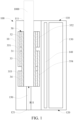
- An embodiment of the present application provides an aerosol generation device 100 that heats but not burns an aerosol generation product 1000, for example, a cigarette, to volatilize or release at least one component of the aerosol generation product 1000 to form an aerosol for inhalation, for example as shown in FIG. 1 .
- a tobacco-contained material that releases volatile compounds from base bodys when being heated is preferably used as the aerosol generation product 1000.
- a non-tobacco material that can be suitable for electrical heating smoke generation after being heated may be used.
- a solid substrate is preferably used as the aerosol generation product 1000, which may include powder, particles, shreds, strips, or flakes of one or more of a vanilla leaf, a tobacco leaf, homogenized tobacco, or expanded tobacco.
- a solid substrate may include additional tobacco or non-tobacco volatile flavor compounds, so as to be released when the base body is heated.
- the aerosol generation product 1000 is received in an aerosol generation device 100, it is advantageous that a portion of the aerosol generation product is exposed outside the aerosol generation device 100, such as a filter tip, for inhalation by a user.
- FIG. 1 A configuration of an aerosol generation device according to an embodiment of the present application may be shown in FIG. 1 .
- the overall shape of the device is roughly configured into a flat cylinder shape, and an external member of the aerosol generation device 100 includes: a housing 10, having a hollow structure inside, to form an assembling space for a component with a necessary function, such as an electronic device and a heating device.
- the housing 10 has a near end 110 and a far end 120 which are opposite to each other in a lengthwise direction.
- the near end 110 is provided with an opening 111.
- the aerosol generation product 1000 may be received in the housing 10 through the opening 111 to be heated or may be removed from the housing 10.
- the far end 120 is provided with an air inlet hole 121.
- the air inlet hole 121 is used for allowing external air to enter the housing 10 in a vaping process
- the aerosol generation device 100 further includes: a chamber, which is used for accommodating or receiving the aerosol generation product 1000. During use, the aerosol generation product 1000 may be removably received in the chamber through the opening 111. In some embodiments, a length of the aerosol generation product 1000 that is surrounded and heated by a heater 30 is greater than 30 mm.
- the aerosol generation device 100 further includes: an air channel 150, which is located between the chamber and the air inlet 121. Therefore, during use, the air channel 150 provides a channel path from the air inlet 121 to the chamber/the aerosol generation product 1000, as shown by the arrow R11 in FIG. 1 .
- the aerosol generation device 100 further includes:
- the aerosol generation device 100 further includes: a heater 30, which at least partially surrounds and defines the chamber.
- the heater 30 at least partially surrounds or encloses the aerosol generation product 1000, and performs heating from an outer circumference of the aerosol generation product 1000.
- the aerosol generation product 1000 is at least partially accommodated and maintained in the heater 30.
- the heater 30 is constructed into a basically elongated tubular shape, and includes:
- the infrared transmitting layer 32 and/or the infrared transmitting layer 33 and/or the infrared transmitting layer 34 are sequentially spaced apart.
- the infrared transmitting layer 32 and/or the infrared transmitting layer 33 and/or the infrared transmitting layer 34 are basically in ring shapes around the base body 31.
- the infrared transmitting layer 32 and/or the infrared transmitting layer 33 and/or the infrared transmitting layer 34 are closed in a circumferential direction.
- the base body 31 has a wall thickness of approximately 0.05 mm to 1 mm; the base body 31 has an inner diameter of approximately 5.0 mm to 8.0 mm; and the base body 31 has a length of approximately 30 mm to 60 mm.
- the infrared transmitting layer 32 and/or the infrared transmitting layer 33 and/or the infrared transmitting layer 34 are formed on an inner surface of the base body 31.
- the infrared transmitting layer 32 and/or the infrared transmitting layer 33 and/or the infrared transmitting layer 34 are coatings or thin layers formed on the base body 31 by deposition, spraying, or the like.
- the infrared transmitting layer 32 and/or the infrared transmitting layer 33 and/or the infrared transmitting layer 34 are thin films wrapped on or combined with the base body 31.
- the infrared transmitting layer 32 and/or the infrared transmitting layer 33 and/or the infrared transmitting layer 34 are electro-induced infrared transmitting layers.
- the infrared transmitting layer 32 and/or the infrared transmitting layer 33 and/or the infrared transmitting layer 34 may be driven by the voltage to transmit infrared ray.
- the infrared transmitting layer 32 and/or the infrared transmitting layer 33 and/or the infrared transmitting layer 34 may be coatings prepared from a ceramic material such as zirconium, an Fe-Mn-Cu material, a tungsten material, a transition metal, and their oxides.
- the infrared transmitting layer 32 and/or the infrared transmitting layer 33 and/or the infrared transmitting layer 34 are composed of an oxide of at least one metal element such as Mg, Al, Ti, Zr, Mn, Fe, Co, Ni, Cu, Cr, and Zn. These metal oxides may transmit far-infrared ray with a heating effect when heated to an appropriate temperature.
- a thickness of the infrared transmitting layer 32 and/or the infrared transmitting layer 33 and/or the infrared transmitting layer 34 may be preferably 30 ⁇ m to 50 ⁇ m.
- a mode of formation on the surface of the tubular base body 31 may be achieved by spraying the oxides of the above metal elements onto the outer surface of the tubular base body 31 through atmospheric plasma spraying and then curing the outer surface.
- the infrared transmitting layer 32, the infrared transmitting layer 33, and the infrared transmitting layer 34 have substantially the same lengths.
- the lengths of the infrared transmitting layer 32, the infrared transmitting layer 33, and the infrared transmitting layer 34 are all 8 mm to 12 mm.
- the lengths of the infrared transmitting layer 32 and/or the infrared transmitting layer 33 and/or the infrared transmitting layer 34 are 9.5 mm.
- the length of any one of the infrared transmitting layer 32 and/or the infrared transmitting layer 33 and/or the infrared transmitting layer 34 is different from the lengths of the other two infrared transmitting layers.
- each of the infrared transmitting layer 32, the infrared transmitting layer33, and the infrared transmitting layer 34 has a length different from the lengths of the other two infrared transmitting layers.
- extension lengths of the infrared transmitting layer 32, the infrared transmitting layer 33, and the infrared transmitting layer 34 gradually change in an axial direction of the heater 30.
- the extension lengths of the infrared transmitting layer 32, the infrared transmitting layer33, and the infrared transmitting layer 34 gradually or sequentially increase.
- the extension lengths of the infrared transmitting layer 32, the infrared transmitting layer33, and the infrared transmitting layer 34 gradually or sequentially decrease.
- the length of the infrared transmitting layer 33 is less than the length of any one of the infrared transmitting layer 32 and the infrared transmitting layer 34. Alternatively, in still some embodiments, the length of the infrared transmitting layer 33 is greater than the length of any one of the infrared transmitting layer 32 and the infrared transmitting layer 34.
- heater 30 may further include three infrared transmitting layers, namely, the infrared transmitting layer 32, the infrared transmitting layer 33, and the infrared transmitting layer 34.
- the heater 30 further includes more infrared transmitting layers, for example, four, five, six, or more infrared transmitting layers sequentially spaced apart in an axial direction of the base body 31.
- FIG. 2 to FIG. 4 show a schematic structural diagram of a heater 30 according to an embodiment.
- the heater 30 includes:
- the infrared transmitting layer 32, the infrared transmitting layer 33, and the infrared transmitting layer 34 are formed on the base body 31 and are sequentially arranged in an axial direction of the base body 31. Certainly, the infrared transmitting layer 32, the infrared transmitting layer 33, and the infrared transmitting layer 34 are spaced apart.
- the infrared transmitting layer 32 is arranged near the first end 311; the infrared transmitting layer 34 is arranged near the second end 312; and the infrared transmitting layer 33 is located between the infrared transmitting layer 32 and the infrared transmitting layer 34.
- the exposed section 313, the exposed section 314, and the exposed section 315 have substantially the same sizes.
- the exposed section 313, the exposed section 314, and the exposed section 315 have lengths of approximately 0.5 mm to 3 mm.
- the length of the exposed section 316 in the axial direction of the base body 31 is greater than the length of the exposed section 313 and/or the length of the exposed section 314 and/or the length of the exposed section 315.
- the length of the exposed section 316 in the axial direction of the base body 31 is between 3 mm and 5 mm.
- temperature measurement identification sections are arranged on the infrared transmitting layer 32, the infrared transmitting layer 33, and the infrared transmitting layer 34, to indicate adhesion of temperature sensors.
- a temperature measurement identification section 321 is arranged on the infrared transmitting layer 32, and is a sprayed identifiable color, or a hollowed hole formed in the infrared transmitting layer 32, or an identifiable graph or pattern, or the like.
- a temperature sensor is bonded to the temperature measurement identification section 321 in a mounted manner, a welded manner, or the like, to accurately sense a temperature of the infrared transmitting layer 32.
- the infrared transmitting layer 33 and the infrared transmitting layer 34 further have temperature measurement identification sections.
- the infrared transmitting layer 32, the infrared transmitting layer 33, and the infrared transmitting layer 34 are all prepared from the same material, so that they have the same infrared radiation wavelength or infrared radiation efficiency during heating of different sections of the aerosol generation product 1000.
- one of the infrared transmitting layer 32, the infrared transmitting layer 33, and the infrared transmitting layer 34 is prepared from a material that is different from materials of the other two infrared transmitting layers, and an infrared transmitting spectrum of one of the infrared transmitting layer 32, the infrared transmitting layer 33, and the infrared transmitting layer 34 and infrared transmitting spectra of the other two infrared transmitting layers have different WLPs (a peak wavelength which is a wavelength corresponding to a maximum radiation power) in its infrared transmitting spectrum from the other two, which can respectively adapt to optimal absorption wavelength ranges of different organic components in the aerosol generation product 1000.
- WLPs a peak wavelength which is a wavelength corresponding to a maximum radiation power
- the infrared transmitting layer 32, the infrared transmitting layer 33, and the infrared transmitting layer 34 are all prepared using different materials, and any two of the infrared transmitting layer 32, the infrared transmitting layer 33, and the infrared transmitting layer 34 have different infrared transmission spectra and/or different WLPs.
- the heater 30 further includes: an electrode coating 351, which has a slender or elongated shape.
- the electrode coating 351 extends from an end portion of the infrared transmitting layer 32 close to the first end 311 to an end portion of the infrared transmitting layer 33 facing away from the infrared transmitting layer 32.
- one portion of the electrode coating 351 is electrically connected to the infrared transmitting layer 32, and the other portion of the electrode coating 351 is further electrically connected to the infrared transmitting layer 33.
- the electrode coating 351 extends from the infrared transmitting layer 32 to the infrared transmitting layer 33.
- an extension length of the electrode coating 351 spans or basically spans the infrared transmitting layer 32 and infrared transmitting layer 33.
- a length of the electrode coating 351 is basically equal to a sum of the lengths of the infrared transmitting layer 32, the exposed section 314, and the infrared transmitting layer 33.
- the heater 30 further includes: an electrode coating 352, which extends in a longitudinal direction of the heater 30. Furthermore, the electrode coating 352 is arranged in a radial direction of the base body 31 or the heater 30 in a manner of facing away from the electrode coating 351. The electrode coating 352 is basically opposite to the electrode coating 351 in the radial direction of the base body 31 or the heater 30. A length of the electrode coating 352 in the axial direction of the heater 30 only covers the infrared transmitting layer 32. The electrode coating 352 is conductively connected to the infrared transmitting layer 32.
- the heater 30 further includes: an electrode coating 353, which includes a portion 3531 and a portion 3532, where the portion 3531 extends in the longitudinal direction of the heater 30, and the portion 3532 extends in the circumferential direction of the heater 30.
- the portion 3532 is closer to the second end 312 than the portion 3531.
- the portion 3531 spans the infrared transmitting layer 34 and is conductively connected to the infrared transmitting layer 34.
- the portion 3532 is located in the exposed section 316, so as to connect the electrode coating 353 to the circuit board 140.
- the heater 30 further includes: an electrode coating 354, which includes a portion 3541 and a portion 3542.
- the portion 3541 extends in the longitudinal direction of the heater 30 the portion 3542 extends in the circumferential direction of the heater 30.
- the portion 3542 is closer to the second end 312 than the portion 3541.
- the portion 3541 spans the infrared transmitting layer 33 and the infrared transmitting layer 34, and is partially conductively connected to the infrared transmitting layer 33 and partially conductively connected to the infrared transmitting layer 34.
- the electrode coating 354 extends from the infrared transmitting layer 33 to the infrared transmitting layer 34.
- an extension length of the electrode coating 354 spans or basically spans the infrared transmitting layer 33 and infrared transmitting layer 34.
- a length of the portion 3541 of the electrode coating 354 is basically equal to a sum of the lengths of the infrared transmitting layer 33, the exposed section 315, and the infrared transmitting layer 34.
- the portion 3542 of the electrode coating 354 is located in the exposed section 316, to connect the electrode coating 354 to the circuit board 140.
- the above electrode coating 351 and/or the electrode coating 352 and/or the electrode coating 353 and/or the electrode coating 354 uses a low-resistivity metal or alloy, such as silver, gold, palladium, platinum, copper, nickel, molybdenum, tungsten, niobium, or an alloy thereof.
- the above electrode coating 351 and/or the electrode coating 352 and/or the electrode coating 353 and/or the electrode coating 354 is formed by spraying, printing, or the like.
- the electrode coating 351 and/or the electrode coating 352 and/or the electrode coating353 and/or the electrode coating 354 are basically in lengthwise shapes.
- the electrode coating 351 and/or the electrode coating 352 and/or the portion 3531 of the electrode coating 353 and/or the portion 3541 of the electrode coating 354 has a width of approximately 2 mm to 4 mm.
- the heater 30 further includes: a conductive element 361, which has a length or a shape that is basically the same as the length or the shape of the electrode coating 351.
- the conductive element 361 is turned on by resisting against or abutting against the electrode coating 351.
- the conductive element 361 is connected to the circuit board 140 through a welded conductive wire 3611, so that the electrode coating 351 is connected to the circuit board 140.
- the heater 30 further includes: a conductive element 362, which has a length or a shape that is basically the same as the length or the shape of the electrode coating 352.
- the conductive element 362 is turned on by resisting against or abutting against the electrode coating 352.
- the conductive element 362 is connected to the circuit board 140 through a welded conductive wire 3621, so that the electrode coating 352 is connected to the circuit board 140.
- the conductive element 361 and/or the conductive element 362 is a relatively thin sheet, and a material is low-resistivity gold, silver, copper, or an alloy thereof.
- the heater 30 further includes: a conductive element 363, which is turned on by abutting against and resisting against the portion 3532 of the electrode coating 353; and a conductive element 364, which is turned on by abutting against and resisting against the portion 3542 of the electrode coating 354.
- the electrode coating 353 and the electrode coating 354 are respectively connected to the circuit board 140.
- the applicant provides the shapes and structures of the conductive element 363 and the conductive element 364, assembling, fixing, and elasticities of the conductive element 363 and the conductive element 364, and other details in Chinese Patent Application No. CN215958354U , which is incorporated by reference in its entirety.
- each of the electrode coating 351 and/or the electrode coating 352 and/or the electrode coating 353 and/or the electrode coating 354 is directly connected to the circuit board 140 through a welding wire.
- the heater 30 further includes: a first temperature sensor, which abuts against the infrared transmitting layer 32 to sense a temperature of the infrared transmitting layer 32; a second temperature sensor, which abuts against the infrared transmitting layer 33 to sense a temperature of the infrared transmitting layer 33; and a third temperature sensor, which abuts against the infrared transmitting layer 34 to sense a temperature of the infrared transmitting layer 34.
- the heater 30 further includes: a thermoplastic clinging member, which encloses the first temperature sensor and/or the second temperature sensor and/or the third temperature sensor outside the heater 30, to cling the first temperature sensor and/or the second temperature sensor and/or the third temperature sensor to the outsides of the infrared transmitting layers.
- a thermoplastic clinging member which encloses the first temperature sensor and/or the second temperature sensor and/or the third temperature sensor outside the heater 30, to cling the first temperature sensor and/or the second temperature sensor and/or the third temperature sensor to the outsides of the infrared transmitting layers.
- the thermoplastic clinging member includes at least one of a heat-resistant synthetic resin, teflon, and silicon. In still some changed embodiments, the thermoplastic clinging member includes a heat shrinkable tube or a high-temperature-resistant tape.
- thermoplastic clinging member is further used for fastening or maintaining one or more of the conductive element 361, the conductive element 362, the conductive element 363, and the conductive element 364.
- the heater 30 further includes: a thermal insulation element, which is used for surrounding or enclosing the infrared transmitting layer 32 and/or the infrared transmitting layer 33 and/or the infrared transmitting layer 34, to provide thermal insulation on the outer sides of the infrared transmitting layer 32 and/or the infrared transmitting layer 33 and/or the infrared transmitting layer 34.
- the thermal insulation element is, for example, a rolled-up aerogel blanket, a porous material, or a vacuum tube.
- the thermal insulation element of the heater 30 is a tube having an inner thermal insulation cavity.
- a thermal insulation cavity is provided between an inner surface and an outer surface of the tubular thermal insulation element.
- a pressure of the thermal insulation cavity is less than an external pressure.
- the thermal insulation element is a vacuum thermal insulation tube having a vacuum degree.
- a thermal insulation cavity is provided between an inner surface and an outer surface of the tubular thermal insulation element, and the thermal insulation cavity is filled with thermal insulation gas, such as argon. At the same pressure and temperature, a heat conduction coefficient of argon is approximately one third less than that of air, thereby effectively providing thermal insulation.
- the circuit board 140 can selectively establish conduction between two or more of the electrode coating 351/the conductive element 361, the electrode coating 352/the conductive element 362, the electrode coating 353/the conductive element 363, and the electrode coating 354/the conductive element 364, to selectively cause one or more of the infrared transmitting layer 32, the infrared transmitting layer 33, and the infrared transmitting layer 34 of the heater 30 to work.
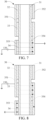
- the electrode coating 351/the conductive element 361 is connected to a positive electrode of the battery cell 130, and the electrode coating 352/the conductive element 362 is connected to a negative electrode of the battery cell 130, a current in the circumferential direction can be formed on the infrared transmitting layer 32, so that the infrared transmitting layer 32 is caused to work, as shown in FIG. 5 .
- the heater 30 transmits the infrared ray through the infrared transmitting layer 32 to heat a section of the aerosol generation product 1000 surrounded by the infrared transmitting layer 32.
- the electrode coating 351/the conductive element 361 is connected to the positive electrode of the battery cell 130, and the electrode coating 354/the conductive element 364 is connected to the negative electrode of the battery cell 130, a current in the circumferential direction can be formed on the infrared transmitting layer 33, so that the infrared transmitting layer 33 is caused to work, as shown in FIG. 6 .
- the heater 30 transmits the infrared ray through the infrared transmitting layer 33 to heat a section of the aerosol generation product 1000 surrounded by the infrared transmitting layer 33.
- the electrode coating 353/the conductive element 363 is connected to the positive electrode of the battery cell 130, and the electrode coating 354/the conductive element 364 is connected to the negative electrode of the battery cell 130, a current in the circumferential direction can be formed on the infrared transmitting layer 34, so that the infrared transmitting layer 34 is caused to work, as shown in FIG. 7 .
- the heater 30 transmits the infrared ray through the infrared transmitting layer 34 to heat a section of the aerosol generation product 1000 surrounded by the infrared transmitting layer 34.
- the conductive coating 354 is used as a conductive intermediate, i.e. an empty electrode, for serial connection between the infrared transmitting layer 33 and the infrared transmitting layer 34, and currents in the circumferential direction can be simultaneously formed on the infrared transmitting layer 33 and the infrared transmitting layer 34, so that the infrared transmitting layer 33 and the infrared transmitting layer 34 are caused to work simultaneously, as shown in FIG. 8 . In this case, the infrared transmitting layer 32 does not work.
- the infrared transmitting layer 33 and the infrared transmitting layer 34 simultaneously transmit infrared rays to simultaneously heat a section of the aerosol generation product 1000 surrounded by the infrared transmitting layer 33 and a section of the aerosol generation product 1000 surrounded by the infrared transmitting layer 34.
- the electrode coating 352/the conductive element 362 when the electrode coating 352/the conductive element 362 is connected to the positive electrode of the battery cell 130, and at the same time, the electrode coating 354/the conductive element 364 is connected to the negative electrode of the battery cell 130, the electrode coating 351 serves as a serial connection intermediate between the infrared transmitting layer 32 and the infrared transmitting layer 33. Currents can be simultaneously formed on the infrared transmitting layer 32 and the infrared transmitting layer 33 in the circumferential direction, so that the infrared transmitting layer 32 and the infrared transmitting layer 33 are caused to work simultaneously, as shown in FIG. 9 . In this case, the infrared transmitting layer 34 does not work.
- the infrared transmitting layer 32 and the infrared transmitting layer 33 simultaneously transmit infrared rays to simultaneously heat a section of the aerosol generation product 1000 surrounded by the infrared transmitting layer 32 and a section of the aerosol generation product 1000 surrounded by the infrared transmitting layer 33.
- the electrode coating 352/the conductive element 362 when the electrode coating 352/the conductive element 362 is connected to the positive electrode of the battery cell 130 and the electrode coating 353/the conductive element 363 is connected to the negative electrode of the battery cell 130, the electrode coating 351 serves as a serial connection intermediate between the infrared transmitting layer 32 and the infrared transmitting layer 33, and the electrode coating 354 serves as a serial connection intermediate between the infrared transmitting layer 33 and the infrared transmitting layer 34.
- the infrared transmitting layer 32, the infrared transmitting layer 33, and the infrared transmitting layer 34 can be caused to work simultaneously, as shown in FIG. 10 .
- the heater 30 simultaneously heats a section of the aerosol generation product 1000 surrounded by the infrared transmitting layer 32, a section of the aerosol generation product 1000 surrounded by the infrared transmitting layer 33, and a section of the aerosol generation product 1000 surrounded by the infrared transmitting layer 34. Namely, in this case, the aerosol generation product 1000 is entirely heated.
- a wire/a conductive element 39 is used to connect the conductive coating 351/the conductive element 361 to the conductive coating 354/the conductive element 364, so that the conductive coating 351 and the conductive coating 354 form an integrally conductive short-circuit state.
- the electrode coating 352/the conductive element 362 is then connected to the positive electrode of the battery cell 130, and the electrode coating 353/the conductive element 363 is then connected to the negative electrode of the battery cell 130.
- the conductive coating 351 and the conductive coating 354 form the short-circuit state by using the wire or the conductive element 39, it can further selectively connect the conductive coating 351/the conductive element 361 to the positive electrode of the battery cell 130 and connect the conductive coating 352/the conductive element 362 to the negative electrode of the battery cell 130.
- it can further connect the electrode coating 353/the conductive element 363 to the positive electrode of the battery cell 130 and connect the electrode coating 354/the conductive element 364 to the negative electrode of the battery cell 130, so that only the infrared transmitting layer 34 works, and the infrared transmitting layer 32 and the infrared transmitting layer 33 do not work.
- any one, two, or three of the infrared transmitting layer 32, the infrared transmitting layer 33, and the infrared transmitting layer 34 work in series.
- an electrode connection control mode is further provided, in which the infrared transmitting layer 32, the infrared transmitting layer 33, and the infrared transmitting layer 34 work simultaneously, but one of the infrared transmitting layer 32, the infrared transmitting layer 33, and the infrared transmitting layer 34 has a higher power.
- the conductive coating 352/the conductive element 362 are connected to the conductive coating 353/the conductive element 353 through the wire or the conductive element 39, so that the conductive coatings/the conductive elements are directly turned on or in a short-circuit state.
- the conductive coating 351/the conductive element 361 is connected to the positive electrode of the battery cell 130, and the conductive coating 352 and/or the conductive coating 353 is connected to the negative electrode, to provide a voltage.
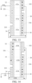
- a current i11 that directly flows from the conductive coating 351 to the conductive coating 352 through the infrared transmitting layer 32, and a current i12 that flows from the conductive coating 351 to the conductive coating 353 through the infrared transmitting layer 33 and the infrared transmitting layer 34 that are connected in series are generated.
- the infrared transmitting layer 32 and the serially connected infrared transmitting layer 33 and infrared transmitting layer 34 form two circuit paths connected in parallel to each other.
- the infrared transmitting layer 32, the infrared transmitting layer 33, and the infrared transmitting layer 34 work simultaneously.
- a resistance of the infrared transmitting layer 32 is less than an equivalent resistance of the infrared transmitting layer 33 and the infrared transmitting layer 34 that are connected in series.
- the resistance of the infrared transmitting layer 32, the resistance of the infrared transmitting layer 33, and the resistance of the infrared transmitting layer 34 are the same and represented by R
- the current i11 flowing through the infrared transmitting layer 32 is twice a current flowing through the infrared transmitting layer 33 and the infrared transmitting layer 34 that are connected in series.
- Power P2 is 1/4 of power P1.
- the section of the aerosol generation product 1000 surrounded by the infrared transmitting layer 32 is heated faster or at a higher temperature than the section surrounded by the infrared transmitting layer 33 and/or the infrared transmitting layer 34.
- the infrared transmitting layer 32 is in a relatively high power density state
- the infrared transmitting layer 33 and/or the infrared transmitting layer 34 is in a relatively low power density state.
- the conductive coating 351/the conductive element 361 is connected to the positive electrode, and the conductive coating 354/the conductive element 364 is connected to the negative electrode, thus providing a voltage.
- a current i11a flowing from the conductive coating 351/the conductive element 361 through the infrared transmitting layer 33 to the conductive coating 354/the conductive element 364 is formed, and a current i12a flowing from the conductive coating 351/the conductive element 361 through the infrared transmitting layer 32 and the infrared transmitting layer 34 that are connected in series to the conductive coating 354/the conductive element 364 is formed, making the power of the infrared transmitting layer 33 four times of the power of the infrared transmitting layer 32 and/or the power of the infrared transmitting layer 34.
- the section of the aerosol generation product 1000 surrounded by the infrared transmitting layer 33 is heated faster or at a
- the conductive coating 353/the conductive element 363 is connected to the positive electrode, and the conductive coating 354/the conductive element 364 is connected to the negative electrode, thus providing a voltage.
- a current i11b flowing from the conductive coating 353/the conductive element 363 through the infrared transmitting layer 34 to the conductive coating 354/the conductive element 364 is formed, and a current i12b flowing from the conductive coating 353/the conductive element 363 through the infrared transmitting layer 32 and the infrared transmitting layer 33 that are connected in series to the conductive coating 354/the conductive element 364 is formed, making the power of the infrared transmitting layer 34 four times of the power of the infrared transmitting layer 32 and/or the power of the infrared transmitting layer 33.
- the section of the aerosol generation product 1000 surrounded by the infrared transmitting layer 34 is heated faster or at a
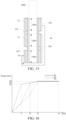
- FIG. 15 shows a schematic diagram of heating different sections of an aerosol generation product 1000 by a heater 30 according to an embodiment.
- the aerosol generation product 1000 includes a section 1100 surrounded and heated by an infrared transmitting layer 32, a section 1200 surrounded and heated by an infrared transmitting layer 33, and a section 1300 surrounded and heated by an infrared transmitting layer 34.
- the section 1100, section 1200, and section 1300 of the aerosol generation product 1000 are respectively located in different heating sections of the heater 30.
- the section 1100 is located in a heating section defined around the infrared transmitting layer 32; the section 1200 is located in a heating section defined around the infrared transmitting layer 33; and the section 1300 is located in a heating section defined around the infrared transmitting layer 34.
- the heater 30 can operate in various situations: only any one or two of the section 1100, the section 1200, and the section 1300 of the aerosol generation product 1000 are heated, or the section 1100, the section 1200, and the section 1300 of the aerosol generation product 1000 are simultaneously heated.
- any one or two of the section 1100, the section 1200, and the section 1300 may be heated faster or at a higher temperature.
- FIG. 16 shows a schematic diagram of a temperature curve of controlling a heater 30 to heat a section 1100, a section 1200, and a section 1300 of an aerosol generation product 1000 according to an embodiment.
- a curve S1 is a temperature curve indicating that the section 1100 is heated by an infrared transmitting layer 32
- a curve S2 is a temperature curve indicating that the section 1200 is heated by an infrared transmitting layer 33
- a curve S3 is a temperature curve indicating that the section 1300 is heated by an infrared transmitting layer 34.
- a heating process includes: Within a first time period (0 to t1), the battery cell 130 supplies power to the heater 30 in the manner shown in FIG.
- the section 1100 is heated faster than the section 1200 and/or the section 1300.
- the section 1100 is heated to a first target temperature which is, for example, temperature T1, and a heating temperature or a current temperature of the section 1200 and/or a heating temperature or a current temperature of the section 1300 is less than the first target temperature.
- the battery cell 130 supplies power to the heater 30 in the manner shown in FIG. 13 , so that the section 1200 is heated faster than the section 1100 and/or the section 1300.
- the section 1200 is heated to a second target temperature, which is, for example, temperature T2, and a heating temperature or a current temperature of the section 1300 is less than the second target temperature.
- the battery cell 130 supplies power to the heater 30 in the manner shown in FIG. 14 , so that the section 1300 is heated faster than the section 1100 and/or the section 1200.
- the section 1300 is heated to a third target temperature, which is, for example, temperature T3.
- the section 1100, the section 1200, and the section 1300 can be heat to an extent that their temperatures are basically close or tend to be close.
- the battery cell 130 supplies power to the heater 30 in the manner shown in FIG. 10 , so that when the section 1100, the section 1200, and the section 1300 are heated basically according to the close powers or temperatures till t4 or until vaping ends.
- the first target temperature T1, the second target temperature T2, and the third target temperature T3 may be the same.
- temperature T1, temperature T2, and temperature T3 may all be set to be approximately 200°C to 300°C.
- the first target temperature, the second target temperature, and the third target temperature are different.
- the first target temperature, the second target temperature, and the third target temperature sequentially or gradually increase or gradually decrease.
- the first target temperature T1, the second target temperature T2, and the third target temperature T3 may gradually increase.
- the first target temperature T1 may be set to 220°C to 250°C; the second target temperature T2 may be set to 240°C to 270°C; and the third target temperature T3 may be set to 260°C to 350°C.
- the temperatures of the section 1100, the section 1200, and the section 1300 are basically maintained to be the third target temperature.
- a length of the first time period is approximately 10 s to 150 s.
- a length of the second time period is approximately 20 s to 40 s.
- a length of the third time period is approximately 40 s to 120 s.
- a length of the fourth time period is approximately 60 s to 150 s.
- the length of the first time period is approximately 130 s.
- the length of the second time period is approximately 25 s.
- the length of the third time period is approximately 100 s.
- the length of the fourth time period is approximately 120 s.
- the length of the fourth time period is greater than the length of the first time period and/or the length of the second time period and/or the length of the third time period. In some embodiments, the length of the first time period is greater than the length of the second time period and/or the length of the third time period.
- the heating processes of the first time period, the second time period, and the third time period are included, and the process of the fourth time period is not included.
- the heating processes of the first time period and the fourth time period are included, and the heating processes of the second time period and the third time period are not included.
- a method for controlling an aerosol generation device to heat a section 1100, a section 1200, and a section 1300 of an aerosol generation product 1000 including: Within a first time period, an infrared transmitting layer 32 of a heater 30 heats the section 1100 at power P10; an infrared transmitting layer 33 heats the section 1200 at power P20; an infrared transmitting layer 34 heats the section 1300 at power P30; power P10 is greater than power P20, and/or power P10 is greater than power P30, and/or power P20 is basically equal to power P30.
- the infrared transmitting layer 32 of the heater 30 heats the section 1100 at power P40; the infrared transmitting layer 33 heats the section 1200 at power P50; and the infrared transmitting layer 34 heats the section 1300 at power P60; and/or, power P50 is greater than power P40, and/or power P50 is greater than power P60, and/or power P50 is basically equal to power P10, and power P40 is basically equal to power P60; and/or, power P40, power P60, power P20, and power P30 are basically the same; and/or, power P40 and/or power P60 is less than power P10.
- the infrared transmitting layer 32 of the heater 30 heats the section 1100 at power P70; the infrared transmitting layer 33 heats the section 1200 at power P80; and the infrared transmitting layer 34 heats the section 1300 at power P90; and/or, power P90 is greater than power P70, and/or power P90 is greater than power P80, and/or power P90 is basically equal to power P10 or power P50; and/or, power P70 is basically equal to power P80.
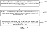
- a method for controlling an aerosol generation device to heat a section 1100, a section 1200, and a section 1300 of an aerosol generation product 1000 is further provided, referring to FIG. 17 , including:
- first time period, the second time period, and the third time period are continuous.
- first time period, the second time period, and the third time period are discontinuous, or an interval exists between the first time period and the second time period, or an interval exists between the second time period and the third time period.
- a method for controlling an aerosol generation device to heat a section 1100, a section 1200, and a section 1300 of an aerosol generation product 1000 including:
- a method for controlling an aerosol generation device to heat a section 1100, a section 1200, and a section 1300 of an aerosol generation product 1000 including:
- the above heater 30 includes: a first resistive heating element, a second resistive heating element, and a third resistive heating element which are sequentially arranged in a longitudinal direction.
- the first resistive heating element is arranged to surround and heat the section 1100.
- the second resistive heating element is arranged to surround and heat the section 1200.
- the third resistive heating element is arranged to surround and heat the section 1300.
- the first resistive heating element and/or the second resistive heating element and/or the third resistive heating element is a pin, a needle, a sheet, or the like that is inserted into different sections of the aerosol generation product 1000 for heating.
- the above heater 30 includes: a first inductive heating element, a second inductive heating element, and a third inductive heating element which are sequentially arranged in the longitudinal direction.
- the first inductive heating element is arranged to surround and heat the section 1100.
- the second inductive heating element is arranged to surround and heat the section 1200.
- the third inductive heating element is arranged to surround and heat the section 1300.
- the first inductive heating element and/or the second inductive heating element and/or the third inductive heating element is a pin, a needle, a sheet, or the like that is inserted into different sections of the aerosol generation product 1000 for heating.
Landscapes
- Resistance Heating (AREA)
- Secondary Cells (AREA)
Abstract
Description
- This application claims priority to
Chinese Patent Application No. 202210970297.9, entitled "AEROSOL GENERATION DEVICE, HEATER FOR AEROSOL GENERATION DEVICE, AND CONTROL METHOD" filed with China National Intellectual Property Administration on August 12, 2022 - Embodiments of the present application relate to the field of heat-not-burn aerosol generation technologies, and in particular, to an aerosol generation device, a heater for an aerosol generation device, and a control method.
- For tobacco products (such as cigarettes and cigars), tobacco is burnt during use to produce tobacco smoke. Attempts are made to replace these tobacco-burning products by making products that release compounds without burning.
- An example of such products is a heating device, which releases compounds by heating rather than burning materials. For example, the material may be tobacco or other non-tobacco products. These non-tobacco products may or may not include nicotine. A known heating device includes a plurality of tubular heaters which are spaced apart in a longitudinal manner and surround tobacco or different sections of other non-tobacco products, and then the plurality of tubular heaters that are spaced apart are independent started to respectively heat tobacco or different sections of other non-tobacco products.
- An embodiment of the present application provides an aerosol generation device, configured to heat an aerosol generation product to generate an aerosol, and including:
- a heater, which is used for heating the aerosol generation product received in the chamber, where a first heating section, a second heating section and a third heating section, which are sequentially arranged, are at least defined on the heater;
- a battery cell, which is used for providing power to the heater; and
- a circuit, which is configured to control the power provided to the heater by the battery cell, to: heat the first heating section faster or at a higher power than heating the second heating section and/or the third heating section within a first time period, heat the second heating section faster or at a higher power than heating the first heating section and/or the third heating section within a second time period, and heat the third heating section faster or at a higher power than heating the first heating section and/or the second heating section within a third time period.
- In some implementations, the first heating section, the second heating section, and the third heating section are sequentially spaced apart.
- In some implementations, the first heating section, the second heating section, and the third heating section are simultaneously heated within the first time period and/or the second time period and/or the third time period.
- In some implementations, the circuit is further configured to control the power provided to the heater by the battery cell, to: at least heat the first heating section within the first time period, at least heat the first heating section and the second heating section within the second time period, and simultaneously heat the first heating section, the second heating section, and the third heating section within the third time period.
- In some implementations, the circuit is further configured to control the power provided to the heater by the battery cell, to: heat, within the first time period, the first heating section to a first target temperature and cause the second heating section and the third heating section to have temperatures less than the first target temperature; heat, within the second time period, the second heating section to a second target temperature and cause the third heating section to have a temperature less than the second target temperature in the second time period; and heat, within the third time period, the third heating section o a third target temperature and cause the first heating section and the second heating section to have temperatures not less than the third target temperature.
- In some implementations, the aerosol generation device includes:
- an opening, where during use, the aerosol generation product is at least partially received in a housing through the opening or is removed from the housing through the opening; and
- the first heating section is closer to the opening than the second heating section and/or the third heating section.
- In some implementations, a length of the first heating section and/or the second heating section and/or the third heating section is from 8 mm to 12 mm;
and/or, the first heating section, the second heating section, and the third heating section have basically the same lengths. - In some implementations, the heater only includes three heating sections.
- In some implementations, the aerosol generation device further includes:
a temperature sensor, which is used for sensing a temperature of the heater. - In some implementations, the heater further includes:
an identification section, which is used for providing an identification when the temperature sensor is connected or bonded to the heater. - In some implementations, the aerosol generation device further includes:
a thermoplastic clinging member, which is used for clinging or fastening the temperature sensor to the heater. - In some implementations, the aerosol generation device further includes:
a thermal insulation element, which is used for providing thermal insulation outside the heater. - In some implementations, the heater includes:
- a first heating element, which at least partially defines the first heating section;
- a second heating element, which at least partially defines the second heating section; and
- a third heating element, which at least partially defines the third heating section.
- In some implementations, the first heating element is at least one of an infrared heating element or a resistive heating element;
- and/or the second heating element is at least one of an infrared heating element or a resistive heating element;
- and/or the third heating element is at least one of an infrared heating element or a resistive heating element.
- In some implementations, within the first time period, the first heating element is connected in parallel with the second heating element and the third heating element connected in series with the second heating element;
- and/or, within the second time period, the second heating element is connected in parallel with the first heating element and the third heating element connected in series with the first heating element;
- and/or, within the third time period, the third heating element is connected in parallel with the first heating element and the second heating element connected in series with the first heating element.
- In some implementations, the circuit is configured to be able to selectively connect any two or three of the first heating element, the second heating element, and the third heating element in series.
- In some implementations, the heater includes: a first electrode element, a second electrode element, a third electrode element, and a fourth electrode element;
- at least a portion of the first heating element is electrically connected between the first electrode element and the second electrode element, so that during use, a current can be guided at the first heating element by the first electrode element and the second electrode element;
- at least a portion of the second heating element is electrically connected between the first electrode element and the fourth electrode element, so that during use, a current can be guided at the second heating element by the first electrode element and the fourth electrode element; and
- at least a portion of the third heating element is electrically connected between the third electrode element and the fourth electrode element, so that during use, a current can be guided at the third heating element by the third electrode element and the fourth electrode element.
- In some implementations, the first electrode element and the second electrode element are oppositely arranged in a radial direction of the heater;
- and/or, the third electrode element and the fourth electrode element are oppositely arranged in the radial direction of the heater;
- and/or, the first electrode element and the third electrode element are spaced apart in a lengthwise direction of the heater;
- and/or, the second electrode element and the fourth electrode element are spaced apart in the lengthwise direction of the heater.
- In some implementations, an extension length of the first electrode element is greater than an extension length of the second electrode element;
and/or, an extension length of the third electrode element is less than an extension length of the fourth electrode element. - In some implementations, at least a portion of the first electrode element extends from the first heating element to the second heating element;
and/or, at least a portion of the fourth electrode element extends from the second heating element to the third heating element. - In some implementations, the second electrode element and the third electrode element are connected and conducted through a wire or a conductive element;
and/or the first electrode element and the fourth electrode element are connected and conducted through a wire or a conductive element. - In some implementations, the heater includes:
a base body; and a first infrared transmitting layer, a second infrared transmitting layer, and a third infrared transmitting layer which are formed on or combined with the base body; at least a portion of the first infrared transmitting layer defines the first heating section; at least a portion of the second infrared transmitting layer defines the second heating section; and at least a portion of the third infrared transmitting layer defines the third heating section. - In some implementations, the first infrared transmitting layer includes a coating or a thin film formed on or combined with the base body;
- and/or, the second infrared transmitting layer includes a coating or a thin film formed on or combined with the base body;
- and/or, the third infrared transmitting layer includes a coating or a thin film formed on or combined with the base body.
- Another embodiment of the present application further provides an aerosol generation device, configured to heat an aerosol generation product to generate an aerosol, and the aerosol generation product includes a first section, a second section, and a third section which are sequentially arranged in a lengthwise direction; the aerosol generation device includes:
- a heater, which is used for heating the aerosol generation product received in a chamber,
- a battery cell, which is used for providing power to the heater; and
- a circuit, configured to control the power provided to the heater by the battery cell, to: cause the heater to simultaneously heat the first section, the second section, and the third section, where a heating power of one of the first section, the second section, and the third section is different from heating powers of the other two sections.
- Another embodiment of the present application further provides an aerosol generation device, configured to heat an aerosol generation product to generate an aerosol, and the aerosol generation product includes a first section, a second section, and a third section which are sequentially arranged in a lengthwise direction; the aerosol generation device further includes:
- a heater, which is used for heating the aerosol generation product received in a chamber,
- a battery cell, which is used for providing power to the heater; and
- a circuit, configured to control the power provided to the heater by the battery cell, to: heat, within a first time period, the first section faster or at a higher power than heating the second section and/or the third section; heat, within a second time period, the second section faster or at a higher power than heating the first section and/or the third section; and heat, within a third time period, the third section faster or at a higher power than heating the first section and/or the second section.
- Another embodiment of the present application further provides an aerosol generation device, configured to heat an aerosol generation product to generate an aerosol, and including:
- a heater, which is used for heating the aerosol generation product received in a chamber, where a first heating section, a second heating section and a third heating section, which are sequentially arranged, are at least defined on the heater;
- a battery cell, which is used for providing power to the heater; and
- the circuit is further configured to control the power provided to the heater by the battery cell, to: at least heat the first heating section within a first time period, at least heat the first heating section and the second heating section within a second time period, and simultaneously heat the first heating section, the second heating section, and the third heating section within a third time period.
- Another embodiment of the present application further provides an aerosol generation device, configured to heat an aerosol generation product to generate an aerosol, and including:
- a heater, which is used for heating the aerosol generation product received in a chamber, where a first heating section, a second heating section and a third heating section, which are sequentially arranged, are at least defined on the heater;
- a battery cell, which is used for providing power to the heater; and
- a circuit, configured to control the power provided to the heater by the battery cell, to: at least heat the first heating section within a first time period, at least heat the second heating section within a second time period, at least heat the third heating section within a third time period, and simultaneously heat the first heating section, the second heating section, and the third heating section within a fourth time period.
- Another embodiment of the present application further provides an aerosol generation device, configured to heat an aerosol generation product to generate an aerosol, and including:
- a heater, which is used for heating the aerosol generation product received in a chamber, where a first heating section, a second heating section and a third heating section, which are sequentially arranged, are at least defined on the heater;
- a battery cell, which is used for providing power to the heater; and
- a circuit, configured to control the power provided to the heater by the battery cell, to: within a first time period, heat the first heating section at a first power and heat the second heating section and the third heating section at basically the same second powers; within a second time period, heat the second heating section at a third power and heat the first heating section and the third heating section at basically the same fourth powers; and within a third time period, heat the third heating section at a fifth power and heat the first heating section and the second heating section at basically the same sixth powers.
- Another embodiment of the present application further provides an aerosol generation device, configured to heat an aerosol generation product to generate an aerosol, and including:
- a heater, which is used for heating the aerosol generation product received in a chamber, where a first heating section, a second heating section and a third heating section, which are sequentially arranged, are at least defined on the heater;
- a battery cell, which is used for providing power to the heater; and
- the circuit, configured to control the power provided to the heater by the battery cell, to: within a first time period, heat the first heating section to a first target temperature and cause the second heating section and the third heating section to have temperatures less than the first target temperature; within the second time period, heat the second heating section to a second target temperature and cause the third heating section to have a temperature less than the second target temperature in the second time period; and within the third time period, heat the third heating section to a third target temperature and cause the first heating section and the second heating section to have temperatures not less than the third target temperature.
- Another embodiment of the present application further provides a heater for an aerosol generation device, including:
- a first end and a second end which face away from each other in a longitudinal direction;
- a first heating element, a second heating element, and a third heating element which are spaced apart in the longitudinal direction, where the first heating element is close to the first end; the third heating element is close to the second end; the second heating element is located between the first heating element and the third heating element;
- and a first electrode element, a second electrode element, a third electrode element, and a fourth electrode element, where at least a portion of the first heating element is electrically connected between the first electrode element and the second electrode element, so that during use, a current is guided at the first heating element by the first electrode element and the second electrode element;
- at least a portion of the second heating element is electrically connected between the first electrode element and the fourth electrode element, so that during use, a current can be guided at the second heating element by the first electrode element and the fourth electrode element; and
- at least a portion of the third heating element is electrically connected between the third electrode element and the fourth electrode element, so that during use, a current can be guided at the third heating element by the third electrode element and the fourth electrode element.
- Another embodiment of the present application further provides a control method for an aerosol generation device. The aerosol generation device is configured to heat an aerosol generation product to generate an aerosol, and the aerosol generation device further includes: a heater, which is used for heating the aerosol generation product received in a chamber, where a first heating section, a second heating section and a third heating section, which are sequentially arranged, are at least defined on the heater; and
- a battery cell, which is used for providing power to the heater; and
- the method includes:
- providing power to the heater;
- within a first time period, heating the first heating section faster or at a higher power than heating the second heating section and/or the third heating section;
- within a second time period, heating the first heating section and/or the third heating section faster or at a higher power than heating the second heating section; and
- within a third time period, heating the first heating section and/or the second heating section faster or at a higher power than heating the third heating section.
- In some other embodiments, the method includes:
controlling the power provided to the heater by the battery cell, to: heat the first heating section faster or at a higher power than heating the second heating section and/or the third heating section within a first time period, heat the second heating section faster or at a higher power than heating the first heating section and/or the third heating section within a second time period, and heat the third heating section faster or at a higher power than heating the first heating section and/or the second heating section within a third time period. - Another embodiment of the present application further provides a control method for an aerosol generation device. The aerosol generation device is configured to heat an aerosol generation product to generate an aerosol, and the aerosol generation device includes: a heater, which is used for heating the aerosol generation product received in a chamber, where a first heating section, a second heating section and a third heating section, which are sequentially arranged, are at least defined on the heater; and
- a battery cell, which is used for providing power to the heater; and
- the method includes:
- providing power to the heater;
- at least heating the first heating section within a first time period;
- at least heating the first heating section and the second heating section within a second time period; and
- simultaneously heating the first heating section, the second heating section, and the third heating section within a third time period.
- In some other embodiments, the method includes:
controlling the power provided to the heater by the battery cell, to: at least heat the first heating section within a first time period, at least heat the first heating section and the second heating section within a second time period, and simultaneously heat the first heating section, the second heating section, and the third heating section within a third time period. - Another embodiment of the present application further provides a control method for an aerosol generation device. The aerosol generation device is configured to heat an aerosol generation product to generate an aerosol, and the aerosol generation device includes: a heater, which is used for heating the aerosol generation product received in a chamber, where a first heating section, a second heating section and a third heating section, which are sequentially arranged, are at least defined on the heater; and
- a battery cell, which is used for providing power to the heater; and
- the method includes:
- providing power to the heater;
- at least heating the first heating section within a first time period;
- at least heating the second heating section within a second time period;
- at least heating the third heating section within a third time period; and
- simultaneously heating the first heating section, the second heating section, and the third heating section within a fourth time period.
- In some other embodiments, the method includes:
controlling the power provided to the heater by the battery cell, to: at least heat the first heating section within a first time period, at least heat the second heating section within a second time period, at least heat the third heating section within a third time period, and simultaneously heat the first heating section, the second heating section, and the third heating section within a fourth time period. - Another embodiment of the present application further provides a control method for an aerosol generation device. The aerosol generation device is configured to heat an aerosol generation product to generate an aerosol, and the aerosol generation device includes: a heater, which is used for heating the aerosol generation product received in a chamber, where a first heating section, a second heating section and a third heating section, which are sequentially arranged, are at least defined on the heater; and
- a battery cell, which is used for providing power to the heater; and
- the method includes:
- providing power to the heater;
- within a first time period, heating the first heating section at a first power and heating the second heating section and the third heating section at basically the same second powers;
- within a second time period, heating the second heating section at a third power and heating the first heating section and the third heating section at basically the same fourth powers; and
- within a third time period, heating the third heating section at a fifth power and heating the first heating section and the second heating section at basically the same sixth powers.
- In some other embodiments, the method includes:
controlling the power provided to the heater by the battery cell, to: within a first time period, heat the first heating section at a first power and heat the second heating section and the third heating section at basically the same second powers; within a second time period, heat the second heating section at a third power and heat the first heating section and the third heating section at basically the same fourth powers; and within a third time period, heat the third heating section at a fifth power and heat the first heating section and the second heating section at basically the same sixth powers. - Another embodiment of the present application further provides a control method for an aerosol generation device. The aerosol generation device is configured to heat an aerosol generation product to generate an aerosol, and the aerosol generation device includes: a heater, which is used for heating the aerosol generation product received in a chamber, where a first heating section, a second heating section and a third heating section, which are sequentially arranged, are at least defined on the heater; and
- a battery cell, which is used for providing power to the heater; and
- the method includes:
- providing power to the heater;
- within a first time period, heating the first heating section to a first target temperature, where the first target temperature is greater than a current temperature of the second heating section and a current temperature of the third heating section;
- within a second time period, heating the second heating section to a second target temperature, where the second target temperature is greater than a current temperature of the third heating section; and
- within a third time period, heating the third heating section to a third target temperature, where the third target temperature is greater than a current temperature of the first heating section and a current temperature of the second heating section.
- In some other embodiments, the method includes:
controlling the power provided to the heater by the battery cell, to: within a first time period, heat the first heating section to a first target temperature and cause the second heating section and the third heating section to have temperatures less than the first target temperature; within the second time period, heat the second heating section to a second target temperature and cause the third heating section to have a temperature less than the second target temperature in the second time period; and within the third time period, heat the third heating section to a third target temperature and cause the first heating section and the second heating section to have temperatures not less than the third target temperature. - Another embodiment of the present application further provides a control method for an aerosol generation device. The aerosol generation device is configured to heat an aerosol generation product to generate an aerosol, and the aerosol generation product includes a first section, a second section, and a third section which are sequentially arranged in a lengthwise direction;
- the aerosol generation device includes: a heater, which is used for heating the aerosol generation product received in a chamber, a battery cell, which is used for providing power to the heater; and
- the method includes:
providing power to the heater, to simultaneously heat the first section, the second section, and the third section, where a heating power of one of the first section, the second section, and the third section is different from heating powers of the other two sections. - In some other embodiments, the method includes:
controlling the power provided to the heater by the battery cell, to: cause the heater to simultaneously heat the first section, the second section, and the third section, where a heating power of one of the first section, the second section, and the third section is different from heating powers of the other two sections. - Another embodiment of the present application further provides a control method for an aerosol generation device. The aerosol generation device is configured to heat an aerosol generation product to generate an aerosol, and the aerosol generation product includes a first section, a second section, and a third section which are sequentially arranged in a lengthwise direction;
- the aerosol generation device includes: a heater, which is used for heating the aerosol generation product received in a chamber; and a battery cell, which is used for providing power to the heater; and
- the method includes:
- providing power to the heater;
- within a first time period, heating the second section and/or the third section faster or at a higher power than heating the first section;
- within a second time period, heating the first section and/or the third section faster or at a higher power than heating the second section; and
- within a third time period, heating the first section and/or the second section faster or at a higher power than heating the third section.
- In some other embodiments, the method includes:
controlling the power provided to the heater by the battery cell, to: heat, within a first time period, the first section faster or at a higher power than heating the second section and/or the third section; heat, within a second time period, the second section faster or at a higher power than heating the first section and/or the third section; and heat, within a third time period, the third section faster or at a higher power than heating the first section and/or the second section. - The above aerosol generation device is advantageous for faster heating required sections in different stages.
- One or more embodiments are exemplarily described with reference to the corresponding figures in the accompanying drawings, and the descriptions are not to be construed as limiting the embodiments. Elements in the accompanying drawings that have same reference numerals are represented as similar elements, and unless otherwise particularly stated, the figures in the accompanying drawings are not drawn to scale.
-
FIG. 1 is a schematic structural diagram of an aerosol generation device according to an embodiment; -
FIG. 2 is a schematic structural diagram of a heater in a viewing angle according to an embodiment; -
FIG. 3 is a schematic exploded view of the heater inFIG. 2 in a viewing angle; -
FIG. 4 is a schematic exploded view of the heater inFIG. 2 in another viewing angle; -
FIG. 5 is a schematic diagram of guiding a current on a heater in an embodiment; -
FIG. 6 is a schematic diagram of guiding a current on a heater in another embodiment; -
FIG. 7 is a schematic diagram of guiding a current on a heater in another embodiment; -
FIG. 8 is a schematic diagram of guiding a current on a heater in another embodiment; -
FIG. 9 is a schematic diagram of guiding a current on a heater in another embodiment; -
FIG. 10 is a schematic diagram of guiding a current on a heater in another embodiment; -
FIG. 11 is a schematic diagram of guiding a current on a heater in another embodiment; -
FIG. 12 is a schematic diagram of guiding a current on a heater in another embodiment; -
FIG. 13 is a schematic diagram of guiding a current on a heater in another embodiment; -
FIG. 14 is a schematic diagram of guiding a current on a heater in another embodiment; -
FIG. 15 is a schematic diagram of heating an aerosol generation product according to another embodiment; -
FIG. 16 is a schematic diagram of a heating curve of different sections of an aerosol generation product according to an embodiment; and -
FIG. 17 is a schematic diagram of a control method of an aerosol generation device according to an embodiment. - For ease of understanding of the present application, the present application is described below in more detail with reference to accompanying drawings and specific implementations.
- An embodiment of the present application provides an
aerosol generation device 100 that heats but not burns anaerosol generation product 1000, for example, a cigarette, to volatilize or release at least one component of theaerosol generation product 1000 to form an aerosol for inhalation, for example as shown inFIG. 1 . - Further, in an optional implementation, a tobacco-contained material that releases volatile compounds from base bodys when being heated is preferably used as the
aerosol generation product 1000. Alternatively, a non-tobacco material that can be suitable for electrical heating smoke generation after being heated may be used. A solid substrate is preferably used as theaerosol generation product 1000, which may include powder, particles, shreds, strips, or flakes of one or more of a vanilla leaf, a tobacco leaf, homogenized tobacco, or expanded tobacco. Alternatively, a solid substrate may include additional tobacco or non-tobacco volatile flavor compounds, so as to be released when the base body is heated. - In addition, as shown in
FIG. 1 , after theaerosol generation product 1000 is received in anaerosol generation device 100, it is advantageous that a portion of the aerosol generation product is exposed outside theaerosol generation device 100, such as a filter tip, for inhalation by a user. - A configuration of an aerosol generation device according to an embodiment of the present application may be shown in
FIG. 1 . The overall shape of the device is roughly configured into a flat cylinder shape, and an external member of theaerosol generation device 100 includes:
ahousing 10, having a hollow structure inside, to form an assembling space for a component with a necessary function, such as an electronic device and a heating device. Thehousing 10 has anear end 110 and afar end 120 which are opposite to each other in a lengthwise direction. - The
near end 110 is provided with anopening 111. Theaerosol generation product 1000 may be received in thehousing 10 through theopening 111 to be heated or may be removed from thehousing 10. - The
far end 120 is provided with anair inlet hole 121. Theair inlet hole 121 is used for allowing external air to enter thehousing 10 in a vaping process - Further, as shown in
FIG. 1 , theaerosol generation device 100 further includes:
a chamber, which is used for accommodating or receiving theaerosol generation product 1000. During use, theaerosol generation product 1000 may be removably received in the chamber through theopening 111. In some embodiments, a length of theaerosol generation product 1000 that is surrounded and heated by aheater 30 is greater than 30 mm. - In addition, as shown in
FIG. 1 , theaerosol generation device 100 further includes:
anair channel 150, which is located between the chamber and theair inlet 121. Therefore, during use, theair channel 150 provides a channel path from theair inlet 121 to the chamber/theaerosol generation product 1000, as shown by the arrow R11 inFIG. 1 . - Further, as shown in
FIG. 1 , theaerosol generation device 100 further includes: - a
battery cell 130 for supplying power, where preferably, thebattery cell 130 is a rechargeable direct-current battery cell 130 and may be connected to an external power supply for charging; and - a
circuit board 140, such as a Printed Circuit Board (PCB), which is provided with a circuit or a Microcontroller Unit (MCU) controller. The circuit may be an integrated circuit. - Further, as shown in
FIG. 1 , theaerosol generation device 100 further includes:
aheater 30, which at least partially surrounds and defines the chamber. When theaerosol generation product 1000 is received in thehousing 10, theheater 30 at least partially surrounds or encloses theaerosol generation product 1000, and performs heating from an outer circumference of theaerosol generation product 1000. Moreover, when received in thehousing 10, theaerosol generation product 1000 is at least partially accommodated and maintained in theheater 30. - Further, referring to
FIG. 2 , theheater 30 is constructed into a basically elongated tubular shape, and includes: - a
tubular base body 31, where a material of thebase body 31 may be an infrared-transmittable material, such as quartz, glass, and ceramic; during use, thebase body 31 is at least partially used for accommodating and maintaining theaerosol generation product 1000; - and an
infrared transmitting layer 32, aninfrared transmitting layer 33, and aninfrared transmitting layer 34 which are formed or arranged on thebase body 31. In this embodiment, theinfrared transmitting layer 32 and/or theinfrared transmitting layer 33 and/or theinfrared transmitting layer 34 are formed on an outer surface of thebase body 31 by deposition, spraying, wrapping, or the like. - The
infrared transmitting layer 32 and/or theinfrared transmitting layer 33 and/or theinfrared transmitting layer 34 are sequentially spaced apart. In addition, theinfrared transmitting layer 32 and/or theinfrared transmitting layer 33 and/or theinfrared transmitting layer 34 are basically in ring shapes around thebase body 31. In addition, theinfrared transmitting layer 32 and/or theinfrared transmitting layer 33 and/or theinfrared transmitting layer 34 are closed in a circumferential direction. - In some specific implementations, the
base body 31 has a wall thickness of approximately 0.05 mm to 1 mm; thebase body 31 has an inner diameter of approximately 5.0 mm to 8.0 mm; and thebase body 31 has a length of approximately 30 mm to 60 mm. - Alternatively, in still some embodiments, the
infrared transmitting layer 32 and/or theinfrared transmitting layer 33 and/or theinfrared transmitting layer 34 are formed on an inner surface of thebase body 31. - In some embodiments, the
infrared transmitting layer 32 and/or theinfrared transmitting layer 33 and/or theinfrared transmitting layer 34 are coatings or thin layers formed on thebase body 31 by deposition, spraying, or the like. Alternatively, in still some embodiments, theinfrared transmitting layer 32 and/or theinfrared transmitting layer 33 and/or theinfrared transmitting layer 34 are thin films wrapped on or combined with thebase body 31. - In this embodiment, the
infrared transmitting layer 32 and/or theinfrared transmitting layer 33 and/or theinfrared transmitting layer 34 are electro-induced infrared transmitting layers. By directly supplying a direct-current voltage to theinfrared transmitting layer 32 and/or theinfrared transmitting layer 33 and/or theinfrared transmitting layer 34, theinfrared transmitting layer 32 and/or theinfrared transmitting layer 33 and/or theinfrared transmitting layer 34 may be driven by the voltage to transmit infrared ray. - In some implementations, the
infrared transmitting layer 32 and/or theinfrared transmitting layer 33 and/or theinfrared transmitting layer 34 may be coatings prepared from a ceramic material such as zirconium, an Fe-Mn-Cu material, a tungsten material, a transition metal, and their oxides. - In some implementations, the
infrared transmitting layer 32 and/or theinfrared transmitting layer 33 and/or theinfrared transmitting layer 34 are composed of an oxide of at least one metal element such as Mg, Al, Ti, Zr, Mn, Fe, Co, Ni, Cu, Cr, and Zn. These metal oxides may transmit far-infrared ray with a heating effect when heated to an appropriate temperature. A thickness of theinfrared transmitting layer 32 and/or theinfrared transmitting layer 33 and/or theinfrared transmitting layer 34 may be preferably 30 µm to 50 µm. A mode of formation on the surface of thetubular base body 31 may be achieved by spraying the oxides of the above metal elements onto the outer surface of thetubular base body 31 through atmospheric plasma spraying and then curing the outer surface. - In some embodiments, the
infrared transmitting layer 32, theinfrared transmitting layer 33, and theinfrared transmitting layer 34 have substantially the same lengths. For example, in a specific embodiment, the lengths of theinfrared transmitting layer 32, theinfrared transmitting layer 33, and theinfrared transmitting layer 34 are all 8 mm to 12 mm. For another example, in a specific embodiment, the lengths of theinfrared transmitting layer 32 and/or theinfrared transmitting layer 33 and/or theinfrared transmitting layer 34 are 9.5 mm. - Alternatively, in still some embodiments, the length of any one of the
infrared transmitting layer 32 and/or theinfrared transmitting layer 33 and/or theinfrared transmitting layer 34 is different from the lengths of the other two infrared transmitting layers. Alternatively, in still some changed embodiments, each of theinfrared transmitting layer 32, the infrared transmitting layer33, and theinfrared transmitting layer 34 has a length different from the lengths of the other two infrared transmitting layers. - Alternatively, in still some embodiments, extension lengths of the
infrared transmitting layer 32, theinfrared transmitting layer 33, and theinfrared transmitting layer 34 gradually change in an axial direction of theheater 30. For example, in some specific embodiments, the extension lengths of theinfrared transmitting layer 32, the infrared transmitting layer33, and theinfrared transmitting layer 34 gradually or sequentially increase. Alternatively, the extension lengths of theinfrared transmitting layer 32, the infrared transmitting layer33, and theinfrared transmitting layer 34 gradually or sequentially decrease. - Alternatively, in still some embodiments, the length of the
infrared transmitting layer 33 is less than the length of any one of theinfrared transmitting layer 32 and theinfrared transmitting layer 34. Alternatively, in still some embodiments, the length of theinfrared transmitting layer 33 is greater than the length of any one of theinfrared transmitting layer 32 and theinfrared transmitting layer 34. - Alternatively, in still some embodiments,
heater 30 may further include three infrared transmitting layers, namely, theinfrared transmitting layer 32, theinfrared transmitting layer 33, and theinfrared transmitting layer 34. Alternatively, in still some embodiments, theheater 30 further includes more infrared transmitting layers, for example, four, five, six, or more infrared transmitting layers sequentially spaced apart in an axial direction of thebase body 31. - Further,
FIG. 2 to FIG. 4 show a schematic structural diagram of aheater 30 according to an embodiment. In this embodiment, theheater 30 includes: - a
first end 311 and asecond end 312 which face away from each other in an axial direction; and - an infrared-
transmittable base body 31, which is constructed into a tubular shape. In an implementation, two ends of thebase body 31 in a lengthwise direction respectively define thefirst end 311 and thesecond end 312 of theheater 30. Furthermore, aninner chamber 310 of thebase body 31 at least partially defines a chamber for receiving theaerosol generation product 1000. - In addition, the
infrared transmitting layer 32, theinfrared transmitting layer 33, and theinfrared transmitting layer 34 are formed on thebase body 31 and are sequentially arranged in an axial direction of thebase body 31. Certainly, theinfrared transmitting layer 32, theinfrared transmitting layer 33, and theinfrared transmitting layer 34 are spaced apart. - Further as shown in
FIG. 2 to FIG. 4 , theinfrared transmitting layer 32 is arranged near thefirst end 311; theinfrared transmitting layer 34 is arranged near thesecond end 312; and theinfrared transmitting layer 33 is located between theinfrared transmitting layer 32 and theinfrared transmitting layer 34. - In addition, the following are further defined on a surface of the base body 31:
- an exposed
section 313, located between thefirst end 311 and theinfrared transmitting layer 32; - an exposed
section 314, located betweeninfrared transmitting layer 32 and theinfrared transmitting layer 33 and separating theinfrared transmitting layer 32 from theinfrared transmitting layer 33; - an exposed
section 315, located betweeninfrared transmitting layer 33 and theinfrared transmitting layer 34 and separating theinfrared transmitting layer 33 from theinfrared transmitting layer 34; and - an exposed
section 316, located between theinfrared transmitting layer 34 and thesecond end 312. - Furthermore, in some embodiments, in the axial direction of the
base body 31, the exposedsection 313, the exposedsection 314, and the exposedsection 315 have substantially the same sizes. For example, in some specific embodiments, the exposedsection 313, the exposedsection 314, and the exposedsection 315 have lengths of approximately 0.5 mm to 3 mm. - In addition, in some embodiments, the length of the exposed
section 316 in the axial direction of thebase body 31 is greater than the length of the exposedsection 313 and/or the length of the exposedsection 314 and/or the length of the exposedsection 315. For example, in some specific embodiments, the length of the exposedsection 316 in the axial direction of thebase body 31 is between 3 mm and 5 mm. - In some embodiments, temperature measurement identification sections are arranged on the
infrared transmitting layer 32, theinfrared transmitting layer 33, and theinfrared transmitting layer 34, to indicate adhesion of temperature sensors. For example, inFIG. 2 to FIG. 4 , a temperaturemeasurement identification section 321 is arranged on theinfrared transmitting layer 32, and is a sprayed identifiable color, or a hollowed hole formed in theinfrared transmitting layer 32, or an identifiable graph or pattern, or the like. During preparation, a temperature sensor is bonded to the temperaturemeasurement identification section 321 in a mounted manner, a welded manner, or the like, to accurately sense a temperature of theinfrared transmitting layer 32. Similarly, theinfrared transmitting layer 33 and theinfrared transmitting layer 34 further have temperature measurement identification sections. - In some embodiments, the
infrared transmitting layer 32, theinfrared transmitting layer 33, and theinfrared transmitting layer 34 are all prepared from the same material, so that they have the same infrared radiation wavelength or infrared radiation efficiency during heating of different sections of theaerosol generation product 1000. - Alternatively, in still some changed embodiments, one of the
infrared transmitting layer 32, theinfrared transmitting layer 33, and theinfrared transmitting layer 34 is prepared from a material that is different from materials of the other two infrared transmitting layers, and an infrared transmitting spectrum of one of theinfrared transmitting layer 32, theinfrared transmitting layer 33, and theinfrared transmitting layer 34 and infrared transmitting spectra of the other two infrared transmitting layers have different WLPs (a peak wavelength which is a wavelength corresponding to a maximum radiation power) in its infrared transmitting spectrum from the other two, which can respectively adapt to optimal absorption wavelength ranges of different organic components in theaerosol generation product 1000. Alternatively, in still some embodiments, theinfrared transmitting layer 32, theinfrared transmitting layer 33, and theinfrared transmitting layer 34 are all prepared using different materials, and any two of theinfrared transmitting layer 32, theinfrared transmitting layer 33, and theinfrared transmitting layer 34 have different infrared transmission spectra and/or different WLPs. - In addition, further as shown in
FIG. 2 to FIG. 4 , theheater 30 further includes:
anelectrode coating 351, which has a slender or elongated shape. Theelectrode coating 351 extends from an end portion of theinfrared transmitting layer 32 close to thefirst end 311 to an end portion of theinfrared transmitting layer 33 facing away from theinfrared transmitting layer 32. Thus, one portion of theelectrode coating 351 is electrically connected to theinfrared transmitting layer 32, and the other portion of theelectrode coating 351 is further electrically connected to theinfrared transmitting layer 33. Alternatively, theelectrode coating 351 extends from theinfrared transmitting layer 32 to theinfrared transmitting layer 33. Alternatively, an extension length of theelectrode coating 351 spans or basically spans theinfrared transmitting layer 32 andinfrared transmitting layer 33. Alternatively, a length of theelectrode coating 351 is basically equal to a sum of the lengths of theinfrared transmitting layer 32, the exposedsection 314, and theinfrared transmitting layer 33. - In addition, the
heater 30 further includes:
anelectrode coating 352, which extends in a longitudinal direction of theheater 30. Furthermore, theelectrode coating 352 is arranged in a radial direction of thebase body 31 or theheater 30 in a manner of facing away from theelectrode coating 351. Theelectrode coating 352 is basically opposite to theelectrode coating 351 in the radial direction of thebase body 31 or theheater 30. A length of theelectrode coating 352 in the axial direction of theheater 30 only covers theinfrared transmitting layer 32. Theelectrode coating 352 is conductively connected to theinfrared transmitting layer 32. - In addition, the
heater 30 further includes:
anelectrode coating 353, which includes aportion 3531 and aportion 3532, where theportion 3531 extends in the longitudinal direction of theheater 30, and theportion 3532 extends in the circumferential direction of theheater 30. Theportion 3532 is closer to thesecond end 312 than theportion 3531. In addition, theportion 3531 spans theinfrared transmitting layer 34 and is conductively connected to theinfrared transmitting layer 34. In addition, theportion 3532 is located in the exposedsection 316, so as to connect theelectrode coating 353 to thecircuit board 140. - In addition, the
heater 30 further includes:
anelectrode coating 354, which includes aportion 3541 and aportion 3542. Theportion 3541 extends in the longitudinal direction of theheater 30 theportion 3542 extends in the circumferential direction of theheater 30. Theportion 3542 is closer to thesecond end 312 than theportion 3541. In addition, theportion 3541 spans theinfrared transmitting layer 33 and theinfrared transmitting layer 34, and is partially conductively connected to theinfrared transmitting layer 33 and partially conductively connected to theinfrared transmitting layer 34. Alternatively, theelectrode coating 354 extends from theinfrared transmitting layer 33 to theinfrared transmitting layer 34. Alternatively, an extension length of theelectrode coating 354 spans or basically spans theinfrared transmitting layer 33 andinfrared transmitting layer 34. Alternatively, a length of theportion 3541 of theelectrode coating 354 is basically equal to a sum of the lengths of theinfrared transmitting layer 33, the exposedsection 315, and theinfrared transmitting layer 34. In addition, theportion 3542 of theelectrode coating 354 is located in the exposedsection 316, to connect theelectrode coating 354 to thecircuit board 140. - In addition, in some embodiments, the
above electrode coating 351 and/or theelectrode coating 352 and/or theelectrode coating 353 and/or theelectrode coating 354 uses a low-resistivity metal or alloy, such as silver, gold, palladium, platinum, copper, nickel, molybdenum, tungsten, niobium, or an alloy thereof. Theabove electrode coating 351 and/or theelectrode coating 352 and/or theelectrode coating 353 and/or theelectrode coating 354 is formed by spraying, printing, or the like. - In addition, in some embodiments, the
electrode coating 351 and/or theelectrode coating 352 and/or the electrode coating353 and/or theelectrode coating 354 are basically in lengthwise shapes. In addition, theelectrode coating 351 and/or theelectrode coating 352 and/or theportion 3531 of theelectrode coating 353 and/or theportion 3541 of theelectrode coating 354 has a width of approximately 2 mm to 4 mm. - In addition, further as shown in
FIG. 2 to FIG. 4 , theheater 30 further includes:
aconductive element 361, which has a length or a shape that is basically the same as the length or the shape of theelectrode coating 351. During assembling, theconductive element 361 is turned on by resisting against or abutting against theelectrode coating 351. Theconductive element 361 is connected to thecircuit board 140 through a weldedconductive wire 3611, so that theelectrode coating 351 is connected to thecircuit board 140. - In addition, further as shown in
FIG. 2 to FIG. 4 , theheater 30 further includes:
aconductive element 362, which has a length or a shape that is basically the same as the length or the shape of theelectrode coating 352. During assembling, theconductive element 362 is turned on by resisting against or abutting against theelectrode coating 352. Theconductive element 362 is connected to thecircuit board 140 through a weldedconductive wire 3621, so that theelectrode coating 352 is connected to thecircuit board 140. - The
conductive element 361 and/or theconductive element 362 is a relatively thin sheet, and a material is low-resistivity gold, silver, copper, or an alloy thereof. - In addition, further as shown in
FIG. 2 to FIG. 4 , theheater 30 further includes:
aconductive element 363, which is turned on by abutting against and resisting against theportion 3532 of theelectrode coating 353; and aconductive element 364, which is turned on by abutting against and resisting against theportion 3542 of theelectrode coating 354. Afterwards, after theconductive element 363 and theconductive element 364 are connected to thecircuit board 140 through wires, theelectrode coating 353 and theelectrode coating 354 are respectively connected to thecircuit board 140. The applicant provides the shapes and structures of theconductive element 363 and theconductive element 364, assembling, fixing, and elasticities of theconductive element 363 and theconductive element 364, and other details in Chinese Patent Application No.CN215958354U , which is incorporated by reference in its entirety. - Alternatively, in some other embodiments, each of the
electrode coating 351 and/or theelectrode coating 352 and/or theelectrode coating 353 and/or theelectrode coating 354 is directly connected to thecircuit board 140 through a welding wire. - Alternatively, in still some embodiments, an implementation for supplying power to the
infrared transmitting layer 32, theinfrared transmitting layer 33, and theinfrared transmitting layer 34 is performed only through theconductive element 361, theconductive element 362, theconductive element 363, and theconductive element 364. - Alternatively, in still some changed embodiments, the
heater 30 further includes:
a first temperature sensor, which abuts against theinfrared transmitting layer 32 to sense a temperature of theinfrared transmitting layer 32; a second temperature sensor, which abuts against theinfrared transmitting layer 33 to sense a temperature of theinfrared transmitting layer 33; and a third temperature sensor, which abuts against theinfrared transmitting layer 34 to sense a temperature of theinfrared transmitting layer 34. - Alternatively, in still some changed embodiments, the
heater 30 further includes:
a thermoplastic clinging member, which encloses the first temperature sensor and/or the second temperature sensor and/or the third temperature sensor outside theheater 30, to cling the first temperature sensor and/or the second temperature sensor and/or the third temperature sensor to the outsides of the infrared transmitting layers. - In some embodiments, the thermoplastic clinging member includes at least one of a heat-resistant synthetic resin, teflon, and silicon. In still some changed embodiments, the thermoplastic clinging member includes a heat shrinkable tube or a high-temperature-resistant tape.
- In addition, in some embodiments, a thermoplastic clinging member is further used for fastening or maintaining one or more of the
conductive element 361, theconductive element 362, theconductive element 363, and theconductive element 364. - Alternatively, in still some changed embodiments, the
heater 30 further includes:
a thermal insulation element, which is used for surrounding or enclosing theinfrared transmitting layer 32 and/or theinfrared transmitting layer 33 and/or theinfrared transmitting layer 34, to provide thermal insulation on the outer sides of theinfrared transmitting layer 32 and/or theinfrared transmitting layer 33 and/or theinfrared transmitting layer 34. The thermal insulation element is, for example, a rolled-up aerogel blanket, a porous material, or a vacuum tube. - Alternatively, in some other changed embodiments, the thermal insulation element of the
heater 30 is a tube having an inner thermal insulation cavity. A thermal insulation cavity is provided between an inner surface and an outer surface of the tubular thermal insulation element. A pressure of the thermal insulation cavity is less than an external pressure. Namely, the thermal insulation element is a vacuum thermal insulation tube having a vacuum degree. Alternatively, in still some changed embodiments, a thermal insulation cavity is provided between an inner surface and an outer surface of the tubular thermal insulation element, and the thermal insulation cavity is filled with thermal insulation gas, such as argon. At the same pressure and temperature, a heat conduction coefficient of argon is approximately one third less than that of air, thereby effectively providing thermal insulation. - In some embodiments, the
circuit board 140 can selectively establish conduction between two or more of theelectrode coating 351/theconductive element 361, theelectrode coating 352/theconductive element 362, theelectrode coating 353/theconductive element 363, and theelectrode coating 354/theconductive element 364, to selectively cause one or more of theinfrared transmitting layer 32, theinfrared transmitting layer 33, and theinfrared transmitting layer 34 of theheater 30 to work. For example:
In a specific embodiment, when theelectrode coating 351/theconductive element 361 is connected to a positive electrode of thebattery cell 130, and theelectrode coating 352/theconductive element 362 is connected to a negative electrode of thebattery cell 130, a current in the circumferential direction can be formed on theinfrared transmitting layer 32, so that theinfrared transmitting layer 32 is caused to work, as shown inFIG. 5 . In this case, theheater 30 transmits the infrared ray through theinfrared transmitting layer 32 to heat a section of theaerosol generation product 1000 surrounded by theinfrared transmitting layer 32. - Moreover, when the
electrode coating 351/theconductive element 361 is connected to the positive electrode of thebattery cell 130, and theelectrode coating 354/theconductive element 364 is connected to the negative electrode of thebattery cell 130, a current in the circumferential direction can be formed on theinfrared transmitting layer 33, so that theinfrared transmitting layer 33 is caused to work, as shown inFIG. 6 . In this case, theheater 30 transmits the infrared ray through theinfrared transmitting layer 33 to heat a section of theaerosol generation product 1000 surrounded by theinfrared transmitting layer 33. - Moreover, when the
electrode coating 353/theconductive element 363 is connected to the positive electrode of thebattery cell 130, and theelectrode coating 354/theconductive element 364 is connected to the negative electrode of thebattery cell 130, a current in the circumferential direction can be formed on theinfrared transmitting layer 34, so that theinfrared transmitting layer 34 is caused to work, as shown inFIG. 7 . In this case, theheater 30 transmits the infrared ray through theinfrared transmitting layer 34 to heat a section of theaerosol generation product 1000 surrounded by theinfrared transmitting layer 34. - Moreover, when the
electrode coating 351/theconductive element 361 is connected to the positive electrode of thebattery cell 130, and theelectrode coating 353/theconductive element 363 is connected to the negative electrode of thebattery cell 130, theconductive coating 354 is used as a conductive intermediate, i.e. an empty electrode, for serial connection between theinfrared transmitting layer 33 and theinfrared transmitting layer 34, and currents in the circumferential direction can be simultaneously formed on theinfrared transmitting layer 33 and theinfrared transmitting layer 34, so that theinfrared transmitting layer 33 and theinfrared transmitting layer 34 are caused to work simultaneously, as shown inFIG. 8 . In this case, theinfrared transmitting layer 32 does not work. In this case, in theheater 30, theinfrared transmitting layer 33 and theinfrared transmitting layer 34 simultaneously transmit infrared rays to simultaneously heat a section of theaerosol generation product 1000 surrounded by theinfrared transmitting layer 33 and a section of theaerosol generation product 1000 surrounded by theinfrared transmitting layer 34. - Moreover, when the
electrode coating 352/theconductive element 362 is connected to the positive electrode of thebattery cell 130, and at the same time, theelectrode coating 354/theconductive element 364 is connected to the negative electrode of thebattery cell 130, theelectrode coating 351 serves as a serial connection intermediate between theinfrared transmitting layer 32 and theinfrared transmitting layer 33. Currents can be simultaneously formed on theinfrared transmitting layer 32 and theinfrared transmitting layer 33 in the circumferential direction, so that theinfrared transmitting layer 32 and theinfrared transmitting layer 33 are caused to work simultaneously, as shown inFIG. 9 . In this case, theinfrared transmitting layer 34 does not work. In this case, in theheater 30, theinfrared transmitting layer 32 and theinfrared transmitting layer 33 simultaneously transmit infrared rays to simultaneously heat a section of theaerosol generation product 1000 surrounded by theinfrared transmitting layer 32 and a section of theaerosol generation product 1000 surrounded by theinfrared transmitting layer 33. - Moreover, when the
electrode coating 352/theconductive element 362 is connected to the positive electrode of thebattery cell 130 and theelectrode coating 353/theconductive element 363 is connected to the negative electrode of thebattery cell 130, theelectrode coating 351 serves as a serial connection intermediate between theinfrared transmitting layer 32 and theinfrared transmitting layer 33, and theelectrode coating 354 serves as a serial connection intermediate between theinfrared transmitting layer 33 and theinfrared transmitting layer 34. In this case, theinfrared transmitting layer 32, theinfrared transmitting layer 33, and theinfrared transmitting layer 34 can be caused to work simultaneously, as shown inFIG. 10 . In this case, theheater 30 simultaneously heats a section of theaerosol generation product 1000 surrounded by theinfrared transmitting layer 32, a section of theaerosol generation product 1000 surrounded by theinfrared transmitting layer 33, and a section of theaerosol generation product 1000 surrounded by theinfrared transmitting layer 34. Namely, in this case, theaerosol generation product 1000 is entirely heated. - In addition, in some embodiments, for example, as shown in
FIG. 11 , in theheater 30, a wire/aconductive element 39 is used to connect theconductive coating 351/theconductive element 361 to theconductive coating 354/theconductive element 364, so that theconductive coating 351 and theconductive coating 354 form an integrally conductive short-circuit state. In this case, theelectrode coating 352/theconductive element 362 is then connected to the positive electrode of thebattery cell 130, and theelectrode coating 353/theconductive element 363 is then connected to the negative electrode of thebattery cell 130. Because of the short circuit between theconductive coating 351 and theconductive coating 354, current does not flow through theinfrared transmitting layer 33, thereby forming a state in which theinfrared transmitting layer 32 and theinfrared transmitting layer 34 work and theinfrared transmitting layer 33 does not work. - Alternatively, when the
conductive coating 351 and theconductive coating 354 form the short-circuit state by using the wire or theconductive element 39, it can further selectively connect theconductive coating 351/theconductive element 361 to the positive electrode of thebattery cell 130 and connect theconductive coating 352/theconductive element 362 to the negative electrode of thebattery cell 130. In this case, a state in which theinfrared transmitting layer 32 works only, and theinfrared transmitting layer 33 and theinfrared transmitting layer 34 do not work. Alternatively, in this case, it can further connect theelectrode coating 353/theconductive element 363 to the positive electrode of thebattery cell 130 and connect theelectrode coating 354/theconductive element 364 to the negative electrode of thebattery cell 130, so that only theinfrared transmitting layer 34 works, and theinfrared transmitting layer 32 and theinfrared transmitting layer 33 do not work. - In the foregoing implementations, by selectively connecting the positive electrode and the negative electrode between different electrode coatings or conductive elements respectively to input a voltage, any one, two, or three of the
infrared transmitting layer 32, theinfrared transmitting layer 33, and theinfrared transmitting layer 34 work in series. - In still another embodiment of the present application, an electrode connection control mode is further provided, in which the
infrared transmitting layer 32, theinfrared transmitting layer 33, and theinfrared transmitting layer 34 work simultaneously, but one of theinfrared transmitting layer 32, theinfrared transmitting layer 33, and theinfrared transmitting layer 34 has a higher power. - For example, in an embodiment shown in
FIG. 12 , theconductive coating 352/theconductive element 362 are connected to theconductive coating 353/theconductive element 353 through the wire or theconductive element 39, so that the conductive coatings/the conductive elements are directly turned on or in a short-circuit state. In this case, theconductive coating 351/theconductive element 361 is connected to the positive electrode of thebattery cell 130, and theconductive coating 352 and/or theconductive coating 353 is connected to the negative electrode, to provide a voltage. In this case, in this state, a current i11 that directly flows from theconductive coating 351 to theconductive coating 352 through theinfrared transmitting layer 32, and a current i12 that flows from theconductive coating 351 to theconductive coating 353 through theinfrared transmitting layer 33 and theinfrared transmitting layer 34 that are connected in series are generated. On a power supply path, theinfrared transmitting layer 32 and the serially connectedinfrared transmitting layer 33 andinfrared transmitting layer 34 form two circuit paths connected in parallel to each other. - In the implementation of
FIG. 12 , theinfrared transmitting layer 32, theinfrared transmitting layer 33, and theinfrared transmitting layer 34 work simultaneously. However, a resistance of theinfrared transmitting layer 32 is less than an equivalent resistance of theinfrared transmitting layer 33 and theinfrared transmitting layer 34 that are connected in series. For example, when the resistance of theinfrared transmitting layer 32, the resistance of theinfrared transmitting layer 33, and the resistance of theinfrared transmitting layer 34 are the same and represented by R, the current i11 flowing through theinfrared transmitting layer 32 is twice a current flowing through theinfrared transmitting layer 33 and theinfrared transmitting layer 34 that are connected in series. The power of theinfrared transmitting layer 32 isP1 = i112 × R. The power of theinfrared transmitting layer 33 and/or theinfrared transmitting layer 34 is P2 = i122 × R. Power P2 is 1/4 of power P1. In this case, the section of theaerosol generation product 1000 surrounded by theinfrared transmitting layer 32 is heated faster or at a higher temperature than the section surrounded by theinfrared transmitting layer 33 and/or theinfrared transmitting layer 34. In the implementation ofFIG. 12 , theinfrared transmitting layer 32 is in a relatively high power density state, and theinfrared transmitting layer 33 and/or theinfrared transmitting layer 34 is in a relatively low power density state. - Alternatively, for another example, in an embodiment shown in
FIG. 13 , theconductive coating 351/theconductive element 361 is connected to the positive electrode, and theconductive coating 354/theconductive element 364 is connected to the negative electrode, thus providing a voltage. In this case, a current i11a flowing from theconductive coating 351/theconductive element 361 through theinfrared transmitting layer 33 to theconductive coating 354/theconductive element 364 is formed, and a current i12a flowing from theconductive coating 351/theconductive element 361 through theinfrared transmitting layer 32 and theinfrared transmitting layer 34 that are connected in series to theconductive coating 354/theconductive element 364 is formed, making the power of theinfrared transmitting layer 33 four times of the power of theinfrared transmitting layer 32 and/or the power of theinfrared transmitting layer 34. In this case, the section of theaerosol generation product 1000 surrounded by theinfrared transmitting layer 33 is heated faster or at a higher temperature than the section surrounded by theinfrared transmitting layer 32 and/or theinfrared transmitting layer 34. - Alternatively, for another example, in an embodiment shown in
FIG. 14 , theconductive coating 353/theconductive element 363 is connected to the positive electrode, and theconductive coating 354/theconductive element 364 is connected to the negative electrode, thus providing a voltage. In this case, a current i11b flowing from theconductive coating 353/theconductive element 363 through theinfrared transmitting layer 34 to theconductive coating 354/theconductive element 364 is formed, and a current i12b flowing from theconductive coating 353/theconductive element 363 through theinfrared transmitting layer 32 and theinfrared transmitting layer 33 that are connected in series to theconductive coating 354/theconductive element 364 is formed, making the power of theinfrared transmitting layer 34 four times of the power of theinfrared transmitting layer 32 and/or the power of theinfrared transmitting layer 33. In this case, the section of theaerosol generation product 1000 surrounded by theinfrared transmitting layer 34 is heated faster or at a higher temperature than the section surrounded by theinfrared transmitting layer 32 and/or theinfrared transmitting layer 33. - Further,
FIG. 15 shows a schematic diagram of heating different sections of anaerosol generation product 1000 by aheater 30 according to an embodiment. In this embodiment shown inFIG. 15 , theaerosol generation product 1000 includes asection 1100 surrounded and heated by aninfrared transmitting layer 32, asection 1200 surrounded and heated by aninfrared transmitting layer 33, and asection 1300 surrounded and heated by aninfrared transmitting layer 34. In this embodiment, thesection 1100,section 1200, andsection 1300 of theaerosol generation product 1000 are respectively located in different heating sections of theheater 30. For example, thesection 1100 is located in a heating section defined around theinfrared transmitting layer 32; thesection 1200 is located in a heating section defined around theinfrared transmitting layer 33; and thesection 1300 is located in a heating section defined around theinfrared transmitting layer 34. During implementation, by selectively connecting theheater 30 to abattery cell 130, theheater 30 can operate in various situations: only any one or two of thesection 1100, thesection 1200, and thesection 1300 of theaerosol generation product 1000 are heated, or thesection 1100, thesection 1200, and thesection 1300 of theaerosol generation product 1000 are simultaneously heated. - In addition, in this embodiment, by selectively connecting the
heater 30 to thebattery cell 130 in a different manner different, when thesection 1100, thesection 1200, and thesection 1300 of theaerosol generation product 1000 are simultaneously heated, any one or two of thesection 1100, thesection 1200, and thesection 1300 may be heated faster or at a higher temperature. - Alternatively, in a specific embodiment, for example,
FIG. 16 shows a schematic diagram of a temperature curve of controlling aheater 30 to heat asection 1100, asection 1200, and asection 1300 of anaerosol generation product 1000 according to an embodiment. Where a curve S1 is a temperature curve indicating that thesection 1100 is heated by aninfrared transmitting layer 32; a curve S2 is a temperature curve indicating that thesection 1200 is heated by aninfrared transmitting layer 33; and a curve S3 is a temperature curve indicating that thesection 1300 is heated by aninfrared transmitting layer 34. A heating process includes:
Within a first time period (0 to t1), thebattery cell 130 supplies power to theheater 30 in the manner shown inFIG. 12 , so that thesection 1100 is heated faster than thesection 1200 and/or thesection 1300. Moreover, within the first time period, thesection 1100 is heated to a first target temperature which is, for example, temperature T1, and a heating temperature or a current temperature of thesection 1200 and/or a heating temperature or a current temperature of thesection 1300 is less than the first target temperature. - With a second time period (t1 to t2), the
battery cell 130 supplies power to theheater 30 in the manner shown inFIG. 13 , so that thesection 1200 is heated faster than thesection 1100 and/or thesection 1300. Within the second time period, thesection 1200 is heated to a second target temperature, which is, for example, temperature T2, and a heating temperature or a current temperature of thesection 1300 is less than the second target temperature. - Within a third time period (t2 to t3), the
battery cell 130 supplies power to theheater 30 in the manner shown inFIG. 14 , so that thesection 1300 is heated faster than thesection 1100 and/or thesection 1200. Within the third time period, thesection 1300 is heated to a third target temperature, which is, for example, temperature T3. In addition, within the third time period, thesection 1100, thesection 1200, and thesection 1300 can be heat to an extent that their temperatures are basically close or tend to be close. - Within a fourth time period (t3 to t4 or at the end), the
battery cell 130 supplies power to theheater 30 in the manner shown inFIG. 10 , so that when thesection 1100, thesection 1200, and thesection 1300 are heated basically according to the close powers or temperatures till t4 or until vaping ends. - In some embodiments, the first target temperature T1, the second target temperature T2, and the third target temperature T3 may be the same. For example, temperature T1, temperature T2, and temperature T3 may all be set to be approximately 200°C to 300°C. Alternatively, in still some embodiments, the first target temperature, the second target temperature, and the third target temperature are different. For example, in some embodiments, the first target temperature, the second target temperature, and the third target temperature sequentially or gradually increase or gradually decrease. For example, in an embodiment, the first target temperature T1, the second target temperature T2, and the third target temperature T3 may gradually increase. For example, in a specific embodiment, the first target temperature T1 may be set to 220°C to 250°C; the second target temperature T2 may be set to 240°C to 270°C; and the third target temperature T3 may be set to 260°C to 350°C. In addition, in the foregoing embodiment, within the fourth time period, the temperatures of the
section 1100, thesection 1200, and thesection 1300 are basically maintained to be the third target temperature. - In some embodiments, a length of the first time period is approximately 10 s to 150 s. A length of the second time period is approximately 20 s to 40 s. A length of the third time period is approximately 40 s to 120 s. A length of the fourth time period is approximately 60 s to 150 s. In a specific embodiment, the length of the first time period is approximately 130 s. The length of the second time period is approximately 25 s. The length of the third time period is approximately 100 s. The length of the fourth time period is approximately 120 s.
- In some embodiments, the length of the fourth time period is greater than the length of the first time period and/or the length of the second time period and/or the length of the third time period. In some embodiments, the length of the first time period is greater than the length of the second time period and/or the length of the third time period.
- Alternatively, in still some changed embodiments, there may be one or more of the first time period, the second time period, the third time period, and the fourth time period in the heating of the
aerosol generation product 1000. For example, only the heating processes of the first time period, the second time period, and the third time period are included, and the process of the fourth time period is not included. Alternatively, only the heating processes of the first time period and the fourth time period are included, and the heating processes of the second time period and the third time period are not included. - Alternatively, in still another embodiment, a method for controlling an aerosol generation device to heat a
section 1100, asection 1200, and asection 1300 of anaerosol generation product 1000 is further provided, including:
Within a first time period, aninfrared transmitting layer 32 of aheater 30 heats thesection 1100 at power P10; aninfrared transmitting layer 33 heats thesection 1200 at power P20; aninfrared transmitting layer 34 heats thesection 1300 at power P30; power P10 is greater than power P20, and/or power P10 is greater than power P30, and/or power P20 is basically equal to power P30. - Within a second time period, the
infrared transmitting layer 32 of theheater 30 heats thesection 1100 at power P40; theinfrared transmitting layer 33 heats thesection 1200 at power P50; and theinfrared transmitting layer 34 heats thesection 1300 at power P60; and/or, power P50 is greater than power P40, and/or power P50 is greater than power P60, and/or power P50 is basically equal to power P10, and power P40 is basically equal to power P60; and/or, power P40, power P60, power P20, and power P30 are basically the same; and/or, power P40 and/or power P60 is less than power P10. - Within a third time period, the
infrared transmitting layer 32 of theheater 30 heats thesection 1100 at power P70; theinfrared transmitting layer 33 heats thesection 1200 at power P80; and theinfrared transmitting layer 34 heats thesection 1300 at power P90; and/or, power P90 is greater than power P70, and/or power P90 is greater than power P80, and/or power P90 is basically equal to power P10 or power P50; and/or, power P70 is basically equal to power P80. - Alternatively, in still another embodiment, a method for controlling an aerosol generation device to heat a
section 1100, asection 1200, and asection 1300 of anaerosol generation product 1000 is further provided, referring toFIG. 17 , including: - S100, within a first time period, the
section 1100 is heated faster or at a higher temperature or at a higher power than thesection 1200 and/or thesection 1300. - S200, within a second time period, the
section 1200 is heated faster or at a higher temperature or at a higher power than thesection 1100 and/or thesection 1300; and - S300, within a third time period, the
section 1300 is heated faster or at a higher temperature or at a higher power than thesection 1100 and/or thesection 1200. - In addition, in some embodiments, the first time period, the second time period, and the third time period are continuous. Alternatively, in still some embodiments, the first time period, the second time period, and the third time period are discontinuous, or an interval exists between the first time period and the second time period, or an interval exists between the second time period and the third time period.
- Alternatively, in still another embodiment, a method for controlling an aerosol generation device to heat a
section 1100, asection 1200, and asection 1300 of anaerosol generation product 1000 is further provided, including: - within a first time period, the
section 1100 is at least heated; thesection 1200 and thesection 1300 can be selectively heated or not heated; - within a second time period, the
section 1200 is at least heated; thesection 1100 and thesection 1300 can be selectively heated or not heated; - within a third time period, the
section 1300 is at least heated; thesection 1100 and thesection 1200 can be selectively heated or not heated; and - within a fourth time period, the
section 1100, thesection 1200, and thesection 1300 are simultaneously heated. - Alternatively, in still another embodiment, a method for controlling an aerosol generation device to heat a
section 1100, asection 1200, and asection 1300 of anaerosol generation product 1000 is further provided, including: - within a first time period, the
section 1100 is at least heated; thesection 1200 and thesection 1300 can be selectively heated or not heated; and - within a second time period, the
section 1100 and thesection 1200 are at least heated; thesection 1300 can be selectively heated or not heated; and - within a third time period, the
section 1100, thesection 1200, and thesection 1300 are simultaneously heated. - Alternatively, in still some changed embodiments, the
above heater 30 includes:
a first resistive heating element, a second resistive heating element, and a third resistive heating element which are sequentially arranged in a longitudinal direction. Where:
The first resistive heating element is arranged to surround and heat thesection 1100. - The second resistive heating element is arranged to surround and heat the
section 1200. - The third resistive heating element is arranged to surround and heat the
section 1300. - Alternatively, in still some embodiments, the first resistive heating element and/or the second resistive heating element and/or the third resistive heating element is a pin, a needle, a sheet, or the like that is inserted into different sections of the
aerosol generation product 1000 for heating. - Alternatively, in still some changed embodiments, the
above heater 30 includes:
a first inductive heating element, a second inductive heating element, and a third inductive heating element which are sequentially arranged in the longitudinal direction. Where:
The first inductive heating element is arranged to surround and heat thesection 1100. - The second inductive heating element is arranged to surround and heat the
section 1200. - The third inductive heating element is arranged to surround and heat the
section 1300. - Alternatively, in still some embodiments, the first inductive heating element and/or the second inductive heating element and/or the third inductive heating element is a pin, a needle, a sheet, or the like that is inserted into different sections of the
aerosol generation product 1000 for heating. - It should be noted that, the specification and the accompanying drawings of the present application illustrate preferred embodiments of the present application, but the present application is not limited to the embodiments described in this specification. Further, a person of ordinary skill in the art can make improvements or transformations according to the above description, and all these improvements and transformations should fall within the scope of protection of the claims attached to the present application.
Claims (37)
- An aerosol generation device, configured to heat an aerosol generation product to generate an aerosol, and comprising:a heater, which is used for heating the aerosol generation product, wherein a first heating section, a second heating section and a third heating section, which are sequentially arranged, are at least defined on the heater in a longitudinal direction;a battery cell, which is used for providing power to the heater; anda circuit, which is configured to control the power provided to the heater by the battery cell, to: heat the first heating section faster or at a higher power than heating the second heating section and/or the third heating section within a first time period, heat the second heating section faster or at a higher power than heating the first heating section and/or the third heating section within a second time period, and heat the third heating section faster or at a higher power than heating the first heating section and/or the second heating section within a third time period.
- The aerosol generation device according to claim 1, wherein the first heating section, the second heating section, and the third heating section are sequentially spaced apart.
- The aerosol generation device according to claim 1 or 2, wherein the first heating section, the second heating section, and the third heating section are simultaneously heated within the first time period and/or the second time period and/or the third time period.
- The aerosol generation device according to claim 1 or 2, wherein the circuit is further configured to control the power provided to the heater by the battery cell, to: at least heat the first heating section within the first time period, at least heat the first heating section and the second heating section within the second time period, and simultaneously heat the first heating section, the second heating section, and the third heating section within the third time period.
- The aerosol generation device according to claim 1 or 2, wherein the circuit is further configured to control the power provided to the heater by the battery cell, to: heat, within the first time period, the first heating section to a first target temperature and cause the second heating section and the third heating section to have temperatures less than the first target temperature; heat, within the second time period, the second heating section to a second target temperature and cause the third heating section to have a temperature less than the second target temperature in the second time period; and heat, within the third time period, the third heating section to a third target temperature and cause the first heating section and the second heating section to have temperatures not less than the third target temperature.
- The aerosol generation device according to claim 1 or 2, comprising:an opening, wherein during use, the aerosol generation product is at least partially received in a housing through the opening or is removed from the housing through the opening; andthe first heating section is closer to the opening than the second heating section and/or the third heating section.
- The aerosol generation device according to claim 1 or 2, wherein a length of the first heating section and/or the second heating section and/or the third heating section is from 8 mm to 12 mm;
and/or, the first heating section, the second heating section, and the third heating section have basically the same lengths. - The aerosol generation device according to claim 1 or 2, wherein the heater only comprises three heating sections.
- The aerosol generation device according to claim 1 or 2, further comprising:
a temperature sensor, which is used for sensing a temperature of the heater. - The aerosol generation device according to claim 9, wherein the heater further comprises:
an identification section, which is used for providing an identification when the temperature sensor is connected or bonded to the heater. - The aerosol generation device according to claim 9, further comprising:
a thermoplastic clinging member, which is used for clinging or fastening the temperature sensor to the heater. - The aerosol generation device according to claim 1 or 2, further comprising:
a thermal insulation element, which is used for providing thermal insulation outside the heater. - The aerosol generation device according to claim 1 or 2, wherein the heater comprises the following elements sequentially arranged in a longitudinal direction:a first heating element, which at least partially defines the first heating section;a second heating element, which at least partially defines the second heating section; anda third heating element, which at least partially defines the third heating section.
- The aerosol generation device according to claim 13, wherein the first heating element is at least one of an infrared heating element or a resistive heating element;and/or the second heating element is at least one of an infrared heating element or a resistive heating element;and/or the third heating element is at least one of an infrared heating element or a resistive heating element.
- The aerosol generation device according to claim 13, wherein within the first time period, the first heating element is connected in parallel with the second heating element and the third heating element connected in series with the second heating element;and/or, within the second time period, the second heating element is connected in parallel with the first heating element and the third heating element connected in series with the first heating element;and/or, within the third time period, the third heating element is connected in parallel with the first heating element and the second heating element connected in series with the first heating element;
- The aerosol generation device according to claim 13, wherein the circuit is configured to be able to selectively connect any two or three of the first heating element, the second heating element, and the third heating element in series.
- The aerosol generation device according to claim 13, wherein the heater comprises: a first electrode element, a second electrode element, a third electrode element, and a fourth electrode element;at least a portion of the first heating element is electrically connected between the first electrode element and the second electrode element, so that during use, a current is guided at the first heating element by the first electrode element and the second electrode element;at least a portion of the second heating element is electrically connected between the first electrode element and the fourth electrode element, so that during use, a current is guided at the second heating element by the first electrode element and the fourth electrode element; andat least a portion of the third heating element is electrically connected between the third electrode element and the fourth electrode element, so that during use, a current is guided at the third heating element by the third electrode element and the fourth electrode element.
- The aerosol generation device according to claim 17, wherein the first electrode element and the second electrode element are oppositely arranged in a radial direction of the heater;and/or, the third electrode element and the fourth electrode element are oppositely arranged in the radial direction of the heater;and/or, the first electrode element and the third electrode element are spaced apart in a lengthwise direction of the heater;and/or, the second electrode element and the fourth electrode element are spaced apart in the lengthwise direction of the heater.
- The aerosol generation device according to claim 17, wherein an extension length of the first electrode element is greater than an extension length of the second electrode element;
and/or, an extension length of the third electrode element is less than an extension length of the fourth electrode element. - The aerosol generation device according to claim 17, wherein at least a portion of the first electrode element extends from the first heating element to the second heating element;
and/or, at least a portion of the fourth electrode element extends from the second heating element to the third heating element. - The aerosol generation device according to claim 17, wherein the second electrode element and the third electrode element are connected and conducted through a wire or a conductive element;
and/or the first electrode element and the fourth electrode element are connected and conducted through a wire or a conductive element. - The aerosol generation device according to claim 1 or 2, wherein the heater comprises:
a base body; and a first infrared transmitting layer, a second infrared transmitting layer, and a third infrared transmitting layer which are formed on or combined with the base body; at least a portion of the first infrared transmitting layer defines the first heating section; at least a portion of the second infrared transmitting layer defines the second heating section; and at least a portion of the third infrared transmitting layer defines the third heating section. - The aerosol generation device according to claim 22, wherein the first infrared transmitting layer comprises a coating or a thin film formed on or combined with the base body;and/or, the second infrared transmitting layer comprises a coating or a thin film formed on or combined with the base body;and/or, the third infrared transmitting layer comprises a coating or a thin film formed on or combined with the base body.
- An aerosol generation device, configured to heat an aerosol generation product to generate an aerosol, wherein the aerosol generation product comprises a first section, a second section, and a third section which are sequentially arranged in a lengthwise direction, wherein the aerosol generation device comprises:a heater, which is used for heating the aerosol generation product,a battery cell, which is used for providing power to the heater; anda circuit, configured to control the power provided to the heater by the battery cell, to: cause the heater to simultaneously heat the first section, the second section, and the third section, wherein a heating power of one of the first section, the second section, and the third section is different from heating powers of the other two sections.
- An aerosol generation device, configured to heat an aerosol generation product to generate an aerosol, wherein the aerosol generation product comprises a first section, a second section, and a third section which are sequentially arranged in a lengthwise direction, wherein the aerosol generation device comprises:a heater, which is used for heating the aerosol generation product;a battery cell, which is used for providing power to the heater; anda circuit, configured to control the power provided to the heater by the battery cell, to: heat, within a first time period, the first section faster or at a higher power than heating the second section and/or the third section; heat, within a second time period, the second section faster or at a higher power than heating the first section and/or the third section; and heat, within a third time period, the third section faster or at a higher power than heating the first section and/or the second section.
- An aerosol generation device, configured to heat an aerosol generation product to generate an aerosol, and comprising:a heater, which is used for heating the aerosol generation product; wherein a first heating section, a second heating section and a third heating section, which are sequentially arranged, are at least defined on the heater in a longitudinal direction;a battery cell, which is used for providing power to the heater; andthe circuit is further configured to control the power provided to the heater by the battery cell, to: at least heat the first heating section within a first time period, at least heat the first heating section and the second heating section within a second time period, and simultaneously heat the first heating section, the second heating section, and the third heating section within a third time period.
- An aerosol generation device, configured to heat an aerosol generation product to generate an aerosol, and comprising:a heater, which is used for heating the aerosol generation product; wherein a first heating section, a second heating section and a third heating section, which are sequentially arranged, are at least defined on the heater in a longitudinal direction;a battery cell, which is used for providing power to the heater; anda circuit, configured to control the power provided to the heater by the battery cell, to: at least heat the first heating section within a first time period, at least heat the second heating section within a second time period, at least heat the third heating section within a third time period, and simultaneously heat the first heating section, the second heating section, and the third heating section within a fourth time period.
- An aerosol generation device, configured to heat an aerosol generation product to generate an aerosol, and comprisinga heater, which is used for heating the aerosol generation product; wherein a first heating section, a second heating section and a third heating section, which are sequentially arranged, are at least defined on the heater in a longitudinal direction;a battery cell, which is used for providing power to the heater; anda circuit, configured to control the power provided to the heater by the battery cell, to: within a first time period, heat the first heating section at a first power and heat the second heating section and the third heating section at basically the same second powers; within a second time period, heat the second heating section at a third power and heat the first heating section and the third heating section at basically the same fourth powers; and within a third time period, heat the third heating section at a fifth power and heat the first heating section and the second heating section at basically the same sixth powers.
- An aerosol generation device, configured to heat an aerosol generation product to generate an aerosol, and comprising:a heater, which is used for heating the aerosol generation product; wherein a first heating section, a second heating section and a third heating section, which are sequentially arranged, are at least defined on the heater in a longitudinal direction;a battery cell, which is used for providing power to the heater; andthe circuit, configured to control the power provided to the heater by the battery cell, to: within a first time period, heat the first heating section to a first target temperature and cause the second heating section and the third heating section to have temperatures less than the first target temperature; within the second time period, heat the second heating section to a second target temperature and cause the third heating section to have a temperature less than the second target temperature in the second time period; and within the third time period, heat the third heating section to a third target temperature and cause the first heating section and the second heating section to have temperatures not less than the third target temperature.
- A heater for an aerosol generation device, comprising:a first end and a second end which face away from each other in a longitudinal direction;a first heating element, a second heating element, and a third heating element which are spaced apart in the longitudinal direction, wherein the first heating element is close to the first end; the third heating element is close to the second end; the second heating element is located between the first heating element and the third heating element;and a first electrode element, a second electrode element, a third electrode element, and a fourth electrode element, wherein at least a portion of the first heating element is electrically connected between the first electrode element and the second electrode element, so that during use, a current is guided at the first heating element by the first electrode element and the second electrode element;at least a portion of the second heating element is electrically connected between the first electrode element and the fourth electrode element, so that during use, a current is guided at the second heating element by the first electrode element and the fourth electrode element; andat least a portion of the third heating element is electrically connected between the third electrode element and the fourth electrode element, so that during use, a current is guided at the third heating element by the third electrode element and the fourth electrode element.
- A control method of an aerosol generation device, wherein the aerosol generation device is configured to heat an aerosol generation product to generate an aerosol; the aerosol generation device comprises: a heater, which is used for heating the aerosol generation product, wherein a first heating section, a second heating section and a third heating section, which are sequentially arranged, are at least defined on the heater in a longitudinal direction; anda battery cell, which is used for providing power to the heater,wherein the method comprises:providing power to the heater;within a first time period, heating the first heating section faster or at a higher power than heating the second heating section and/or the third heating section;within a second time period, heating the first heating section and/or the third heating section faster or at a higher power than heating the second heating section; andwithin a third time period, heating the first heating section and/or the second heating section faster or at a higher power than heating the third heating section.
- A control method of an aerosol generation device, wherein the aerosol generation device is configured to heat an aerosol generation product to generate an aerosol; the aerosol generation device comprises: a heater, which is used for heating the aerosol generation product, wherein a first heating section, a second heating section and a third heating section, which are sequentially arranged, are at least defined on the heater in a longitudinal direction; anda battery cell, which is used for providing power to the heater,wherein the method comprises:providing power to the heater;at least heating the first heating section within a first time period;at least heating the first heating section and the second heating section within a second time period; andsimultaneously heating the first heating section, the second heating section, and the third heating section within a third time period.
- A control method of an aerosol generation device, wherein the aerosol generation device is configured to heat an aerosol generation product to generate an aerosol; the aerosol generation device comprises: a heater, which is used for heating the aerosol generation product, wherein a first heating section, a second heating section and a third heating section, which are sequentially arranged, are at least defined on the heater in a longitudinal direction; anda battery cell, which is used for providing power to the heater,wherein the method comprises:providing power to the heater;at least heating the first heating section within a first time period;at least heating the second heating section within a second time period;at least heating the third heating section within a third time period; andsimultaneously heating the first heating section, the second heating section, and the third heating section within a fourth time period.
- A control method of an aerosol generation device, wherein the aerosol generation device is configured to heat an aerosol generation product to generate an aerosol; the aerosol generation device comprises: a heater, which is used for heating the aerosol generation product, wherein a first heating section, a second heating section and a third heating section, which are sequentially arranged, are at least defined on the heater in a longitudinal direction; anda battery cell, which is used for providing power to the heater,wherein the method comprises:providing power to the heater;within a first time period, heating the first heating section at a first power and heating the second heating section and the third heating section at basically the same second powers;within a second time period, heating the second heating section at a third power and heating the first heating section and the third heating section at basically the same fourth powers; andwithin a third time period, heating the third heating section at a fifth power, the first heating section and the second heating section at basically the same sixth powers.
- A control method of an aerosol generation device, wherein the aerosol generation device is configured to heat an aerosol generation product to generate an aerosol; the aerosol generation device comprises: a heater, which is used for heating the aerosol generation product, wherein a first heating section, a second heating section and a third heating section, which are sequentially arranged, are at least defined on the heater in a longitudinal direction; anda battery cell, which is used for providing power to the heater,wherein the method comprises:providing power to the heater;within a first time period, heating the first heating section to a first target temperature, wherein the first target temperature is greater than a current temperature of the second heating section and a current temperature of the third heating section;within a second time period, heating the second heating section to a second target temperature, wherein the second target temperature is greater than a current temperature of the third heating section; andwithin a third time period, heating the third heating section to a third target temperature, wherein the third target temperature tends to be close to a current temperature of the first heating section and a current temperature of the second heating section.
- A control method of an aerosol generation device, wherein the aerosol generation device is configured to heat an aerosol generation product to generate an aerosol; the aerosol generation product comprises a first section, a second section, and a third section which are sequentially arranged in a lengthwise direction;the aerosol generation device comprises: a heater, which is used for heating the aerosol generation product; a battery cell, which is used for providing power to the heater,wherein the method comprises:
providing power to the heater, to simultaneously heat the first section, the second section, and the third section, wherein a heating power of one of the first section, the second section, and the third section is different from heating powers of the other two sections. - A control method of an aerosol generation device, wherein the aerosol generation device is configured to heat an aerosol generation product to generate an aerosol; the aerosol generation product comprises a first section, a second section, and a third section which are sequentially arranged in a lengthwise direction;the aerosol generation device comprises: a heater, which is used for heating the aerosol generation product; and a battery cell, which is used for providing power to the heater,wherein the method comprises:providing power to the heater;within a first time period, heating the second section and/or the third section faster or at a higher power than heating the first section;within a second time period, heating the first section and/or the third section faster or at a higher power than heating the second section; andwithin a third time period, heating the first section and/or the second section faster or at a higher power than heating the third section.
Applications Claiming Priority (2)
| Application Number | Priority Date | Filing Date | Title |
|---|---|---|---|
| CN202210970297.9A CN117617570A (en) | 2022-08-12 | 2022-08-12 | Aerosol generating device, heater for aerosol generating device and control method |
| PCT/CN2023/111793 WO2024032625A1 (en) | 2022-08-12 | 2023-08-08 | Aerosol generation device, heater for aerosol generation device, and control method |
Publications (2)
| Publication Number | Publication Date |
|---|---|
| EP4541209A1 true EP4541209A1 (en) | 2025-04-23 |
| EP4541209A4 EP4541209A4 (en) | 2025-11-26 |
Family
ID=89850987
Family Applications (1)
| Application Number | Title | Priority Date | Filing Date |
|---|---|---|---|
| EP23851846.8A Pending EP4541209A4 (en) | 2022-08-12 | 2023-08-08 | Aerosol generation device, heater for aerosol generation device and control method |
Country Status (6)
| Country | Link |
|---|---|
| US (1) | US20260020615A1 (en) |
| EP (1) | EP4541209A4 (en) |
| JP (1) | JP2025526136A (en) |
| KR (1) | KR20250047393A (en) |
| CN (1) | CN117617570A (en) |
| WO (1) | WO2024032625A1 (en) |
Families Citing this family (4)
| Publication number | Priority date | Publication date | Assignee | Title |
|---|---|---|---|---|
| CN120678266A (en) * | 2024-03-22 | 2025-09-23 | 深圳麦时科技有限公司 | Heat-not-burn device and heating control method thereof |
| CN120938163A (en) * | 2024-05-14 | 2025-11-14 | 深圳市合元科技有限公司 | Aerosol generating device and heater for aerosol generating device |
| CN121264722A (en) * | 2024-07-05 | 2026-01-06 | 深圳市合元科技有限公司 | Aerosol generating device and control method thereof |
| KR20260014771A (en) * | 2024-07-24 | 2026-02-02 | 주식회사 케이티앤지 | Device for generating aerosol |
Family Cites Families (25)
| Publication number | Priority date | Publication date | Assignee | Title |
|---|---|---|---|---|
| US10004259B2 (en) * | 2012-06-28 | 2018-06-26 | Rai Strategic Holdings, Inc. | Reservoir and heater system for controllable delivery of multiple aerosolizable materials in an electronic smoking article |
| US20170119050A1 (en) * | 2015-10-30 | 2017-05-04 | British American Tobacco (Investments) Limited | Article for Use with Apparatus for Heating Smokable Material |
| JP6930804B2 (en) * | 2016-06-29 | 2021-09-01 | ニコベンチャーズ トレーディング リミテッド | Goods for use with equipment for heating smoking materials |
| US11793239B2 (en) * | 2017-08-09 | 2023-10-24 | Philip Morris Products S.A. | Aerosol generating system with multiple susceptors |
| CN108391856A (en) * | 2018-04-13 | 2018-08-14 | 深圳瀚星翔科技有限公司 | A kind of electronics heating control system, electronic heating apparatus and its method for heating and controlling |
| GB201809786D0 (en) * | 2018-06-14 | 2018-08-01 | Nicoventures Trading Ltd | Induction heating system and heater |
| CN108851244B (en) * | 2018-07-24 | 2024-07-12 | 深圳麦克韦尔科技有限公司 | Baking smoking set and vacuum heat-insulating heating assembly |
| GB201812507D0 (en) * | 2018-07-31 | 2018-09-12 | Nicoventures Holdings Ltd | aerosol generation |
| GB201907702D0 (en) * | 2019-05-30 | 2019-07-17 | Nicoventures Trading Ltd | Aerosol generation |
| GB201909343D0 (en) * | 2019-06-28 | 2019-08-14 | Nicoventures Trading Ltd | Aerosol provision device |
| PL3760065T3 (en) * | 2019-07-04 | 2022-01-03 | Philip Morris Products S.A. | Aerosol-generating device comprising an inductive heating arrangement comprising first and second lc circuits having different resonance frequencies |
| GB201917474D0 (en) * | 2019-11-29 | 2020-01-15 | Nicoventures Trading Ltd | Electronic aerosol provision system |
| CN211794320U (en) * | 2019-12-06 | 2020-10-30 | 深圳市余看智能科技有限公司 | Heating device and heater for smoking products |
| GB202000722D0 (en) * | 2020-01-17 | 2020-03-04 | Nicoventures Trading Ltd | Aerosol-generating device |
| US12484610B2 (en) * | 2020-04-16 | 2025-12-02 | R.J. Reynolds Tobacco Company | Aerosol delivery device including a segregated substrate |
| US20230189898A1 (en) * | 2020-05-15 | 2023-06-22 | Jt International Sa | Aerosol Generation Device, Aerosol Generation System, Control Method |
| JP7527397B2 (en) * | 2020-06-13 | 2024-08-02 | ニコベンチャーズ トレーディング リミテッド | Aerosol generating device |
| CN114098166A (en) * | 2020-09-01 | 2022-03-01 | 深圳市合元科技有限公司 | Aerosol generating device and infrared heater |
| CN112471601B (en) * | 2020-11-27 | 2025-04-18 | 上海烟草集团有限责任公司 | Multi-stage temperature control method, multi-stage heating device and computer readable storage medium |
| CN114631647A (en) * | 2020-12-16 | 2022-06-17 | 比亚迪股份有限公司 | Electronic cigarette and heating method thereof, storage medium, electronic device |
| CN215347055U (en) * | 2021-03-15 | 2021-12-31 | 深圳市合元科技有限公司 | Aerosol generating device |
| CN215958354U (en) | 2021-05-12 | 2022-03-08 | 深圳市合元科技有限公司 | Heater and smoking set comprising same |
| CN114009846B (en) * | 2021-11-16 | 2024-05-28 | 北京温致科技有限公司 | Power supply device and aerosol generating device |
| CN114009849B (en) * | 2021-12-02 | 2024-08-27 | 北京温致科技有限公司 | Computer program product, aerosol-generating device and heating control method thereof |
| CN218999525U (en) * | 2022-08-12 | 2023-05-12 | 深圳市合元科技有限公司 | Gas mist generating device and heater for gas mist generating device |
-
2022
- 2022-08-12 CN CN202210970297.9A patent/CN117617570A/en active Pending
-
2023
- 2023-08-08 WO PCT/CN2023/111793 patent/WO2024032625A1/en not_active Ceased
- 2023-08-08 KR KR1020257008224A patent/KR20250047393A/en active Pending
- 2023-08-08 US US18/995,531 patent/US20260020615A1/en active Pending
- 2023-08-08 EP EP23851846.8A patent/EP4541209A4/en active Pending
- 2023-08-08 JP JP2025507881A patent/JP2025526136A/en active Pending
Also Published As
| Publication number | Publication date |
|---|---|
| US20260020615A1 (en) | 2026-01-22 |
| EP4541209A4 (en) | 2025-11-26 |
| KR20250047393A (en) | 2025-04-03 |
| CN117617570A (en) | 2024-03-01 |
| WO2024032625A1 (en) | 2024-02-15 |
| JP2025526136A (en) | 2025-08-07 |
Similar Documents
| Publication | Publication Date | Title |
|---|---|---|
| US20260020615A1 (en) | Aerosol generation device, heater for aerosol generation device, and control method | |
| JP7787941B2 (en) | Electrically heated smoking system with improved heater | |
| US12458073B2 (en) | Vapor generation device and infrared emitter | |
| EP4209137A1 (en) | Aerosol generation apparatus and infrared heater | |
| CN218999525U (en) | Gas mist generating device and heater for gas mist generating device | |
| CN220109139U (en) | Gas mist generating device and heater for gas mist generating device | |
| CN218354633U (en) | Gas mist generating device and heater for gas mist generating device | |
| CN116616507A (en) | Aerosol generating device and heater for aerosol generating device | |
| EP4544936A1 (en) | Aerosol generating device, heater for aerosol generating device, and control method | |
| CN220875944U (en) | Aerosol generating device and heater for aerosol generating device | |
| RU2857629C2 (en) | Aerosol-generating device | |
| US20250064125A1 (en) | Aerosol generating device and resistive heater for aerosol generating device | |
| EP4691290A1 (en) | Vapor generating device, and heater for vapor generating device | |
| EP4678040A1 (en) | Aerosol generating device, and heater and control method for aerosol generating device | |
| CN222941805U (en) | Aerosol generating device and heater for aerosol generating device | |
| EP4678035A1 (en) | Aerosol generating device and heater for aerosol generating device | |
| EP4678038A1 (en) | Aerosol generating apparatus, and heater for aerosol generating apparatus | |
| CN118805973A (en) | Aerosol generating device, heater for aerosol generating device and control method | |
| JP2025536811A (en) | Aerosol generator, heater for aerosol generator, and manufacturing method |
Legal Events
| Date | Code | Title | Description |
|---|---|---|---|
| STAA | Information on the status of an ep patent application or granted ep patent |
Free format text: STATUS: THE INTERNATIONAL PUBLICATION HAS BEEN MADE |
|
| PUAI | Public reference made under article 153(3) epc to a published international application that has entered the european phase |
Free format text: ORIGINAL CODE: 0009012 |
|
| STAA | Information on the status of an ep patent application or granted ep patent |
Free format text: STATUS: REQUEST FOR EXAMINATION WAS MADE |
|
| 17P | Request for examination filed |
Effective date: 20250114 |
|
| AK | Designated contracting states |
Kind code of ref document: A1 Designated state(s): AL AT BE BG CH CY CZ DE DK EE ES FI FR GB GR HR HU IE IS IT LI LT LU LV MC ME MK MT NL NO PL PT RO RS SE SI SK SM TR |
|
| DAV | Request for validation of the european patent (deleted) | ||
| DAX | Request for extension of the european patent (deleted) | ||
| A4 | Supplementary search report drawn up and despatched |
Effective date: 20251024 |
|
| RIC1 | Information provided on ipc code assigned before grant |
Ipc: A24F 40/50 20200101AFI20251020BHEP Ipc: A24F 40/46 20200101ALI20251020BHEP Ipc: A24F 40/57 20200101ALI20251020BHEP |