EP4541208A1 - Aerosol generating apparatus and heater for aerosol generating apparatus - Google Patents
Aerosol generating apparatus and heater for aerosol generating apparatus Download PDFInfo
- Publication number
- EP4541208A1 EP4541208A1 EP23854239.3A EP23854239A EP4541208A1 EP 4541208 A1 EP4541208 A1 EP 4541208A1 EP 23854239 A EP23854239 A EP 23854239A EP 4541208 A1 EP4541208 A1 EP 4541208A1
- Authority
- EP
- European Patent Office
- Prior art keywords
- aerosol generating
- heating member
- flange
- generating apparatus
- heating
- Prior art date
- Legal status (The legal status is an assumption and is not a legal conclusion. Google has not performed a legal analysis and makes no representation as to the accuracy of the status listed.)
- Pending
Links
Images



Classifications
-
- A—HUMAN NECESSITIES
- A24—TOBACCO; CIGARS; CIGARETTES; SIMULATED SMOKING DEVICES; SMOKERS' REQUISITES
- A24F—SMOKERS' REQUISITES; MATCH BOXES; SIMULATED SMOKING DEVICES
- A24F40/00—Electrically operated smoking devices; Component parts thereof; Manufacture thereof; Maintenance or testing thereof; Charging means specially adapted therefor
- A24F40/40—Constructional details, e.g. connection of cartridges and battery parts
-
- H—ELECTRICITY
- H05—ELECTRIC TECHNIQUES NOT OTHERWISE PROVIDED FOR
- H05B—ELECTRIC HEATING; ELECTRIC LIGHT SOURCES NOT OTHERWISE PROVIDED FOR; CIRCUIT ARRANGEMENTS FOR ELECTRIC LIGHT SOURCES, IN GENERAL
- H05B3/00—Ohmic-resistance heating
- H05B3/10—Heating elements characterised by the composition or nature of the materials or by the arrangement of the conductor
- H05B3/16—Heating elements characterised by the composition or nature of the materials or by the arrangement of the conductor the conductor being mounted on an insulating base
-
- A—HUMAN NECESSITIES
- A24—TOBACCO; CIGARS; CIGARETTES; SIMULATED SMOKING DEVICES; SMOKERS' REQUISITES
- A24F—SMOKERS' REQUISITES; MATCH BOXES; SIMULATED SMOKING DEVICES
- A24F40/00—Electrically operated smoking devices; Component parts thereof; Manufacture thereof; Maintenance or testing thereof; Charging means specially adapted therefor
- A24F40/40—Constructional details, e.g. connection of cartridges and battery parts
- A24F40/46—Shape or structure of electric heating means
-
- A—HUMAN NECESSITIES
- A24—TOBACCO; CIGARS; CIGARETTES; SIMULATED SMOKING DEVICES; SMOKERS' REQUISITES
- A24F—SMOKERS' REQUISITES; MATCH BOXES; SIMULATED SMOKING DEVICES
- A24F40/00—Electrically operated smoking devices; Component parts thereof; Manufacture thereof; Maintenance or testing thereof; Charging means specially adapted therefor
- A24F40/50—Control or monitoring
-
- A—HUMAN NECESSITIES
- A24—TOBACCO; CIGARS; CIGARETTES; SIMULATED SMOKING DEVICES; SMOKERS' REQUISITES
- A24F—SMOKERS' REQUISITES; MATCH BOXES; SIMULATED SMOKING DEVICES
- A24F40/00—Electrically operated smoking devices; Component parts thereof; Manufacture thereof; Maintenance or testing thereof; Charging means specially adapted therefor
- A24F40/50—Control or monitoring
- A24F40/51—Arrangement of sensors
-
- A—HUMAN NECESSITIES
- A24—TOBACCO; CIGARS; CIGARETTES; SIMULATED SMOKING DEVICES; SMOKERS' REQUISITES
- A24F—SMOKERS' REQUISITES; MATCH BOXES; SIMULATED SMOKING DEVICES
- A24F40/00—Electrically operated smoking devices; Component parts thereof; Manufacture thereof; Maintenance or testing thereof; Charging means specially adapted therefor
- A24F40/50—Control or monitoring
- A24F40/57—Temperature control
-
- H—ELECTRICITY
- H05—ELECTRIC TECHNIQUES NOT OTHERWISE PROVIDED FOR
- H05B—ELECTRIC HEATING; ELECTRIC LIGHT SOURCES NOT OTHERWISE PROVIDED FOR; CIRCUIT ARRANGEMENTS FOR ELECTRIC LIGHT SOURCES, IN GENERAL
- H05B3/00—Ohmic-resistance heating
- H05B3/40—Heating elements having the shape of rods or tubes
- H05B3/42—Heating elements having the shape of rods or tubes non-flexible
-
- A—HUMAN NECESSITIES
- A24—TOBACCO; CIGARS; CIGARETTES; SIMULATED SMOKING DEVICES; SMOKERS' REQUISITES
- A24F—SMOKERS' REQUISITES; MATCH BOXES; SIMULATED SMOKING DEVICES
- A24F40/00—Electrically operated smoking devices; Component parts thereof; Manufacture thereof; Maintenance or testing thereof; Charging means specially adapted therefor
- A24F40/20—Devices using solid inhalable precursors
-
- A—HUMAN NECESSITIES
- A24—TOBACCO; CIGARS; CIGARETTES; SIMULATED SMOKING DEVICES; SMOKERS' REQUISITES
- A24F—SMOKERS' REQUISITES; MATCH BOXES; SIMULATED SMOKING DEVICES
- A24F40/00—Electrically operated smoking devices; Component parts thereof; Manufacture thereof; Maintenance or testing thereof; Charging means specially adapted therefor
- A24F40/70—Manufacture
-
- H—ELECTRICITY
- H05—ELECTRIC TECHNIQUES NOT OTHERWISE PROVIDED FOR
- H05B—ELECTRIC HEATING; ELECTRIC LIGHT SOURCES NOT OTHERWISE PROVIDED FOR; CIRCUIT ARRANGEMENTS FOR ELECTRIC LIGHT SOURCES, IN GENERAL
- H05B2203/00—Aspects relating to Ohmic resistive heating covered by group H05B3/00
- H05B2203/002—Heaters using a particular layout for the resistive material or resistive elements
- H05B2203/007—Heaters using a particular layout for the resistive material or resistive elements using multiple electrically connected resistive elements or resistive zones
-
- H—ELECTRICITY
- H05—ELECTRIC TECHNIQUES NOT OTHERWISE PROVIDED FOR
- H05B—ELECTRIC HEATING; ELECTRIC LIGHT SOURCES NOT OTHERWISE PROVIDED FOR; CIRCUIT ARRANGEMENTS FOR ELECTRIC LIGHT SOURCES, IN GENERAL
- H05B2203/00—Aspects relating to Ohmic resistive heating covered by group H05B3/00
- H05B2203/013—Heaters using resistive films or coatings
-
- H—ELECTRICITY
- H05—ELECTRIC TECHNIQUES NOT OTHERWISE PROVIDED FOR
- H05B—ELECTRIC HEATING; ELECTRIC LIGHT SOURCES NOT OTHERWISE PROVIDED FOR; CIRCUIT ARRANGEMENTS FOR ELECTRIC LIGHT SOURCES, IN GENERAL
- H05B2203/00—Aspects relating to Ohmic resistive heating covered by group H05B3/00
- H05B2203/016—Heaters using particular connecting means
-
- H—ELECTRICITY
- H05—ELECTRIC TECHNIQUES NOT OTHERWISE PROVIDED FOR
- H05B—ELECTRIC HEATING; ELECTRIC LIGHT SOURCES NOT OTHERWISE PROVIDED FOR; CIRCUIT ARRANGEMENTS FOR ELECTRIC LIGHT SOURCES, IN GENERAL
- H05B2203/00—Aspects relating to Ohmic resistive heating covered by group H05B3/00
- H05B2203/02—Heaters using heating elements having a positive temperature coefficient
Definitions
- tobacco is burned to produce tobacco smoke. Attempts are made to replace these tobacco-burning products by making products that release compounds without burning.
- the material may be tobacco or other non-tobacco products. These non-tobacco products may or may not include nicotine.
- a pin-shaped or needle-shaped resistance heater is inserted into tobacco or other non-tobacco products for heating.
- An embodiment of this application provides an aerosol generating apparatus configured to heat an aerosol generating product to generate an aerosol, including:
- the outer surface of the first section is black; and/or the outer surface of the second section is white.
- the outer surface of the first section is opaque.
- the heater includes: a surface coating that coats or is formed on the first section and avoids the second section, and therefore the surface coating defines different colors of the outer surface of the first section and the outer surface of the second section.
- the surface coating includes silicon dioxide and zirconia.
- a length of the first section is greater than a length of the second section.
- the outer surface of the second section is rougher than the outer surface of the first section, such that the outer surface of the second section has greater friction to prevent the flange from moving relative to the second section.
- the aerosol generating apparatus further includes:
- the flange includes a first surface close to or facing the free front end; and the first surface has the same color as the outer surface of the first section.
- the flange includes a first surface close to or facing the free front end; and the first surface is substantially flush with a joint between the first section and the second section.
- the first surface has the same color as the outer surface of the first section.
- the first surface is black.
- the first surface is asymmetrical in at least one of the length direction or a width direction.
- the first surface has an asymmetry of rotating by 180° around a central axis of the heating member.
- the first surface is approximately D-shaped.
- the flange further includes:
- the flange includes an outer side surface surrounding the flange in a circumferential direction, where the outer side surface includes at least one flat plane and at least one curved cambered surface.
- the flange includes an outer side surface surrounding the flange in a circumferential direction of the flange; and the outer side surface is asymmetrical with respect to a central axis of the heating member.
- the curved cambered surface is a circular arc surface; and the heating member is arranged substantially coaxially with a virtual cylinder defined by the curved cambered surface.
- the heater further includes: a coating material at least partially covering a joint gap between the flange and the heating member on the first surface, to prevent residues or an aerosol condensate from the aerosol generating product from entering the joint gap along an outer surface of the heating member.
- the heater further includes: a bonding material at least partially entering or penetrating into a joint gap between the flange and the heating member from the first surface, to securely bond the flange to the heating member.
- the bonding material includes at least one of glaze, glass or a ceramic.
- the flange includes the flange includes a first surface close to or facing the free front end and a second surface facing away from the first surface; and a joint gap between the flange and the heating member is invisible through the first surface; and the joint gap between the flange and the heating member is visible through the second surface.
- a thermal conductivity of the flange is less than 5 W/(m•K).
- the flange includes a ceramic.
- the flange includes zirconia.
- the flange extends in the length direction of the heater by a dimension of 1-4 mm.
- a distance between the flange and the tail end is 2-5 mm.
- a distance between the flange and the tail end is greater than the dimension by which the flange extends in the length direction of the heater.
- a cavity axially extending to the tail end is provided in the heating member.
- an inner diameter of the cavity is greater than 1/2 of an outer diameter of the heating member.
- an inner diameter of the cavity is 0.8-1.5 mm.
- the heating member is configured to be tubular, and the cavity is defined by a tubular hollow; and the heating member has a tube wall thickness of 0.2-0.5 mm.
- the heating member is configured to be heated from room temperature to 350°C within 10 s under supply power of 10-15 W.
- the heating member is formed by winding a sheet.
- the heating member is formed by winding the sheet clockwise.
- the heating member has more than one winding layer formed by winding the sheet.
- the sheet includes:
- the substrate includes a ceramic.
- the substrate includes zirconia.
- the substrate is a thin film formed by casting a ceramic slurry including a ceramic raw material and an organic solvent.
- the sheet has a thickness of 0.05-0.2 mm.
- the heating member includes a non-integral number of winding layers.
- the heating member includes 3.5 winding layers.
- the heating member includes:
- the resistance heating track avoids the second section.
- the flange includes:
- a diameter of a virtual cylinder defined by the second side surface is greater than a width dimension of the flange.
- a minimum distance between a central axis of the heating member and the first side surface is less than a distance between the central axis of the heating member and the second side surface; and/or a maximum distance between the central axis of the heating member and the first side surface is greater than the distance between the central axis of the heating member and the second side surface.
- a radian of the second side surface is substantially equal to ⁇ .
- the flange includes an outer side surface surrounding the flange in a circumferential direction of the flange, and the outer side surface has or includes only a non-closed annular circular arc surface.
- the heating member includes: a substrate and a resistance heating track combined on the substrate.
- the resistance heating track includes: a plurality of track segments circuitously extending in a length direction and a circumferential direction of the heating member.
- the resistance heating track includes only a plurality of straightly extending track segments; and/or the resistance heating track has no arc-shaped curved track segment.
- the resistance heating track is defined with: an electrical connection region close to the tail end, to conduct a current on the resistance heating track.
- a track width of the resistance heating track in the electrical connection region is greater than that in other parts.
- the resistance heating track includes at least one track segment extending in a circumferential direction of the heating member
- the heater further includes: a conductive pin electrically connected to the heating member, to conduct a current on the heating member.
- the conductive pin has a diameter of 0.2-0.5 mm.
- the conductive pin has a length of 20-30 mm.
- the conductive pin includes: copper and a nickel layer coating the copper.
- a position at which the conductive pin is electrically connected to the heating member is located in the first section.
- the heating member is defined with an electrical connection region for electrical connection with the conductive pin; and the electrical connection region is closer to the free front end than the flange.
- a distance between the electrical connection region and the flange is greater than 1 mm.
- the conductive pin is not exposed on an outer surface of the first section.
- the heater further includes: a covering layer covering at least the conductive pin outside the heating member to fasten the conductive pin to the heating member.
- the covering layer is formed by cooling and solidifying a molten precursor outside the heating member.
- the covering layer includes glass, glaze or tin.
- the covering layer is partially surrounded by the flange and partially exposed outside the flange.
- the heating member is defined with an electrical connection region for electrical connection with the conductive pin; and a covering layer formed by cooling and solidifying a molten precursor in the electrical connection region, and at least partially covering the electrical connection region.
- a wire groove is provided in an inner side wall of the flange around the heating member; and the conductive pin is at least partially accommodated and held in the wire groove.
- the heating member is configured to be tubular; and the heater further includes: an end member close to and defining the free front end; and the end member at least partially extends into the heating member.
- an outer diameter of at least part of the end member is configured to gradually decrease in a direction close to the free front end.
- Another embodiment of this application further provides an aerosol generating apparatus configured to heat an aerosol generating product to generate an aerosol, including:
- Another embodiment of this application further provides an aerosol generating apparatus configured to heat an aerosol generating product to generate an aerosol, including:
- Another embodiment of this application further provides an aerosol generating apparatus configured to heat an aerosol generating product to generate an aerosol, including:
- Another embodiment of this application further provides an aerosol generating apparatus configured to heat an aerosol generating product to generate an aerosol, including:
- the heating member includes 3.5 winding layers.
- Another embodiment of this application further provides an aerosol generating apparatus configured to heat an aerosol generating product to generate an aerosol, including:
- Another embodiment of this application further provides an aerosol generating apparatus configured to heat an aerosol generating product to generate an aerosol, including:
- Another embodiment of this application further provides an aerosol generating apparatus configured to heat an aerosol generating product to generate an aerosol, including: a heating member for being inserted into the aerosol generating product for heating, where the heating member includes:
- Another embodiment of this application further provides an aerosol generating apparatus configured to heat an aerosol generating product to generate an aerosol, including:
- Another embodiment of this application further provides an aerosol generating apparatus configured to heat an aerosol generating product to generate an aerosol, including: a heating member for being inserted into the aerosol generating product for heating, where the heating member has a cavity extending in a length direction; and an inner diameter of the cavity is greater than 1/2 of an outer diameter of the heating member, such that the heating member can be heated from room temperature to 350°C within 10 s under supply power of 10-15 W.
- Another embodiment of this application further provides an aerosol generating apparatus configured to heat an aerosol generating product to generate an aerosol, including:
- Another embodiment of this application further provides an aerosol generating apparatus configured to heat an aerosol generating product to generate an aerosol, including:
- Another embodiment of this application further provides an aerosol generating apparatus configured to heat an aerosol generating product to generate an aerosol, including:
- Another embodiment of this application further provides an aerosol generating apparatus configured to heat an aerosol generating product to generate an aerosol, including:
- Another embodiment of this application further provides an aerosol generating apparatus configured to heat an aerosol generating product to generate an aerosol, including:
- Another embodiment of this application further provides a heater for an aerosol generating apparatus, including a free front end and a tail end facing away from each other in a length direction, and
- Another embodiment of this application further provides a heater for an aerosol generating apparatus, including a free front end and a tail end facing away from each other in a length direction, and
- Another embodiment of this application further provides a heater for an aerosol generating apparatus, including a free front end and a tail end facing away from each other in a length direction, and
- Another embodiment of this application further provides a heater for an aerosol generating apparatus, including a free front end and a tail end facing away from each other in a length direction, and
- Another embodiment of this application further provides a heater for an aerosol generating apparatus, including a free front end and a tail end facing away from each other in a length direction, and
- Another embodiment of this application further provides a heater for an aerosol generating apparatus, including a free front end and a tail end facing away from each other in a length direction, and a heating member at least partially extending in front of a free front end and a tail end, to be inserted into the aerosol generating product for heating, where the heating member includes:
- Another embodiment of this application further provides a heater for an aerosol generating apparatus, including a free front end and a tail end facing away from each other in a length direction, and
- Different color sections are formed on the heating member of the aerosol generating apparatus, such that identification and positioning by a color sensor or device in automatic assembly or preparation are facilitated.
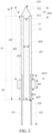
- An embodiment of this application provides an aerosol generating apparatus, with a structure shown in FIG. 1 , including:
- a direct current supply voltage provided by the battery cell 10 ranges from about 2.5 V to about 9.0 V, and an amperage of a direct current that can be provided by the battery cell 10 ranges from about 2.5 A to about 20 A.
- the heater 30 is generally in the shape of a pin, a needle, a rod, a bar, a column, a sheet or a plate, which is advantageous for insertion into the aerosol generating product 1000; and in addition, the heater 30 may have a length of approximately 12-25 millimeters and an outer diameter of approximately 2-4 millimeters.
- the aerosol generating product 1000 is preferably made of a tobacco containing material that releases volatile compounds from a matrix when heated, or may be made of a non-tobacco material that can be suitable for electric heating smoke formation after being heated.
- the aerosol generating product 1000 is preferably made of a solid matrix, which may include one or more of a powder, particles, fragments, strips, or sheets of one or more of vanilla leaves, tobacco leaves, homogeneous tobacco, and expanded tobacco; or the solid matrix may contain additional tobacco or non-tobacco volatile aroma compounds to be released when the matrix is heated.
- the heater 30 may generally include a resistance heating element, and an auxiliary base material for assisting the resistance heating element in fixation, preparation, and the like.
- the resistance heating element is in the shape or form of a spiral coil.
- the resistance heating element is in the form of a conductive track combined on the substrate.
- the resistance heating element is in the shape of a sheet.
- FIG. 2 and FIG. 3 each are a schematic diagram of a heater 30 according to an embodiment.
- the heater 30 according to this embodiment includes a free front end 310 and a tail end 320 facing away from each other in a length direction, where the free front end 310 has a tapered tip for insertion into the aerosol generating product 1000.
- the heater 30 includes:
- the end member 32 includes: a portion 321 and a portion 322 that are sequentially arranged in a length direction, where an outer diameter or a cross-sectional area of the portion 321 is configured in a tapered shape gradually decreasing towards the free front end 310, and the portion 322 is in a columnar shape; and during assembly, the portion 322 extends into the cavity 37 of the heating member 31 from the end of the heating member 31 close to the free front end 310; and the portion 321 abuts against the end of the heating member 31 close to the free front end 310.
- the cavity 37 is closed or blocked by the end member 32 at a position close to the free front end 310.
- the cavity 37 is open at the tail end 320 and is defined with an opening.
- the portion 321 has a maximum outer diameter at a position facing away from the free front end 310 or adjacent to portion 322; the maximum outer diameter of the portion 321 is basically the same as an outer diameter of heating member 31; an outer diameter of the portion 322 is the same as an inner diameter of the cavity 37; and then a step is defined between the portion 321 and the portion 322 to abut against the end of the heating member 31 close to the free front end 310.
- the portion 321 of the end member 32 is exposed outside the heating member 31, while the portion 322 extends into the heating member 31.
- the heater 30 further includes: a flange 33 at least partially surrounding or combined with the heating member 31; and moreover, the flange 33 is closer to the tail end 320 than to the free front end 310.
- the aerosol generating apparatus 100 enables the heater 30 to be stably assembled in the aerosol generating apparatus 100 by clamping or holding the flange 33.
- the heating member 31 penetrates or passes through the flange 33.
- a length d11 by which the heater 30 extends is approximately 12-25 mm; and in a specific embodiment, the length d11 by which the heater 30 extends is 19 mm.
- a distance d12 between the flange 33 and the free front end 310 is approximately 10-16 mm; and in a specific embodiment, the distance d12 between the flange 33 and the free front end 310 is 14 mm.
- a length d13 by which the heating member 31 extends is approximately 14-18 mm; and in a specific embodiment, the length d13 by which the heating member 31 extends is approximately 16 mm. The length d13 by which the heating member 31 is greater than 80% of the length d11 by which the heater 30 extends.
- a wall thickness of the tubular heating member 31 is approximately 0.2-0.5 mm. In a specific embodiment, the wall thickness of the tubular heating member 31 is 0.4 mm.
- a distance d14 between the flange 33 and the tail end 320 is approximately 2-5 mm; and in a specific embodiment, the distance d14 between the flange 33 and the tail end 320 is 3 mm.
- a dimension d15 by which the flange 33 extends in a length direction of the heater 30 is approximately 1-4 mm; and in a specific embodiment, the dimension d15 by which the flange 33 extends is 1.95 mm. The dimension d15 by which the flange 33 extends is less than the distance d14.
- a dimension d16 by which the end member 32 extends in the length direction of the heater 30 is approximately 3-6 mm; and in a specific embodiment, the dimension d16 by which the end member 32 extends is 4 mm.
- a length of the portion 321 of the end member 32 is greater than a length of the portion 322.
- the length of the portion 321 is approximately 2-4 mm, and the length of the portion 322 is approximately 1-2 mm.
- a length d17 by which the cavity 37 extends is approximately 12-16 mm; and in a specific embodiment, the length d17 by which the cavity 37 extends is 15 mm.
- An inner diameter d18 of the cavity 37 is approximately 0.8-1.5 mm; and in a specific embodiment, the inner diameter d18 of the cavity 37 is 1.3 mm. In some embodiments, the inner diameter d18 of the cavity 37 is greater than 1/2 of the outer diameter of heating member 31. This is beneficial to limiting the volume and heat capacity of the heating member 31 and improving heating efficiency during use.
- the heating member 31 can be heated from room temperature to 350°C within 10 s under supply power of 10-15 W.
- the flange 33 includes zirconia.
- the flange 33 is molded from the above moldable material, such as the PEEK or the ceramic, around the heating member 31.
- a thermal conductivity of the flange 33 is less than 5 W/(m•K), which is beneficial to reducing more heat transfer from the heating member 31 to the flange 33. In some other embodiments, the thermal conductivity of the flange 33 is less than 3 W/(m•K); and in some other embodiments, the thermal conductivity of the flange 33 is approximately 2 W/(m•K).
- the end member 32 is made of a metal, or an alloy, or a ceramic, or the like. In some embodiments, the end member 32 includes a ceramic, such as a zirconia ceramic.
- the flange 33 has a surface 3310 and a surface 3320 that face away from each other in a circumferential direction, and an outer side surface 3330 extending between the surface 3310 and the surface 3320.
- the outer side surface 3330 surrounds the flange 33 in the circumferential direction. It can be understood that the surface 3310 and the surface 3320 are a first surface and a second surface.
- the surface 3310 and the surface 3320 have different colors, which is beneficial to identifying an orientation in preparation and assembly.
- the surface 3310 has a color different from that of the surface 3320 and/or that of the outer side surface 3330.
- a color difference of the surface 3310 is sufficient to be recognized by a color sensor or by human eyes.
- the surface 3310 is black.
- the surface 3320 and/or the outer side surface 3330 is white.
- the surface 3310 is exposed to the chamber. After assembly, the surface 3310 is flush with an inner bottom wall of the chamber facing away from the opening 40.
- the heating member 31 includes a section 41 and a section 42 sequentially arranged in the length direction.
- the section 41 is mainly a portion for insertion into the aerosol generating product 1000 for heating, and the section 42 is mainly a portion used for mounting and fixing.
- the section 41 is close to the free front end 310 and the section 42 is close to the tail end 320.
- a length of the first section 41 is greater than a length of the second section 42.
- the section 41 may have a length of approximately 8-12 mm, and the section 42 may have a length of 4-6 mm. It can be understood that the section 41 and the section 42 are a first section and a second section.
- an outer surface of the section 41 of the heating member 31 has a color different from that of the section 42, to provide a positioning indication for combining the flange 33 with the heating member 31.
- a surface of the section 41 is black; and a surface of the section 42 is white.
- the flange 33 surrounds and is combined on the section 42. After assembly, the surface 3310 of the flange 33 is flush with a joint between the section 41 and the section 42 and the like. After assembly, the section 42 extends at least partially out of the flange 33.
- the outer surface of the section 42 is rougher than the outer surface of the section 41, so that when the flange 33 surrounds and is combined on the section 42, the section 42 has relatively larger surface friction than the section 41, which is beneficial to preventing the flange 33 from moving relative to the section 42 and/or the heating member 31 in an axial direction.
- the heater 30 further includes: a bonding material or a coating material covering or closing the gap 3340 at the surface 3310, or the bonding material further at least partially penetrates into the gap 3340, to tightly bond the flange 33 to the heating member 31.
- the gap 3340 is covered or closed by the bonding material or the coating material, to prevent residues or an aerosol condensate from the aerosol generating product 1000 from flowing or penetrating along the surface of the section 41 into the gap 3340 and/or between the flange 33 and the section 42.
- the bonding material or the coating material includes, for example, glaze, glass, a ceramic, and the like.
- the outer surface of the section 41 of the heating member 31, the surface 3310 of the flange 33, and an outer surface of the end member 32 form colors different from those of other parts, to facilitate identification and positioning by a color sensor or device in automatic assembly or preparation.
- the outer surface of the section 41 of the heating member 31, the surface 3310 of the flange 33, and the outer surface of the end member 32 are configured in black.
- the color of the outer surface of the section 41 is opaque. For example, black surface coatings are formed by spraying or surface treatment, and the like to make their outer surfaces black.
- the surface coating includes silicon dioxide and zirconia.
- the heater 30 further includes: a conductive pin 351 and a conductive pin 352 for supplying power to the heating member 31 or for conducting a current on the heating member 31.
- the conductive pin 351 and/or the conductive pin 352 has the same length.
- a length d19 by which the conductive pin 351 and/or the conductive pin 352 extends is approximately 20-30 mm.
- the conductive pin 351 and/or the conductive pin 352 has a diameter of 0.2-0.5 mm.
- the conductive pin 351 and/or the conductive pin 352 has a diameter of 0.35 mm.
- the conductive pin 351 and/or the conductive pin 352 is made of a metal or an alloy with low resistivity.
- the conductive pin 351 and/or the conductive pin 352 includes gold, silver, copper or an alloy thereof.
- the conductive pin 351 and/or the conductive pin 352 is a copper wire with a surface electroplated or sprayed or coated with a nickel layer.
- the conductive pin 351 and/or the conductive pin 352 passes through the flange 33.
- the conductive pin 351 and/or the conductive pin 352 is connected to the section 41 of the heating member 31.
- a position at which the conductive pin 351 and/or the conductive pin 352 is connected to the heating member 31 is closer to the free front end 310 than the flange 33.
- a distance d151 between the flange 33 and the position at which the conductive pin 351 and/or the conductive pin 352 is connected to the heating member 31 is greater than 1 mm.
- the distance d151 is between 1 mm and 3 mm.
- the conductive pin 351 and/or the conductive pin 352 is not exposed or is exposed outside the heating member 31 and/or the section 41; and the conductive pin 351 and/or the conductive pin 352 extends to the outside of the tail end 320 from the position at which the conductive pin and/or the conductive pin is connected to the heating member 31, and then is connected to the circuit 20.
- the heating member 31 is formed by winding a sheet 31a.
- the heating member 31 includes at least two winding layers.
- FIG. 4 is a schematic diagram of a sheet 31a after a heating member 31 is unfolded in a circumferential direction in an embodiment.
- the sheet 31a wound to form the heating member 31 includes:
- the windable substrate 3110a is a thin film formed, by a casting process in a casting device, from a ceramic slurry formed by mixing a ceramic powder with an organic solvent.
- the windable substrate 3110a has a thickness of approximately 0.05-0.2 mm.
- the substrate 3110a formed by casting the ceramic slurry includes zirconia.
- the organic solvent is usually an organic solvent in the field of ceramic preparation, and usually includes one or more of anhydrous alcohol, toluene, xylene, tetrahydrofuran, tripropylene glycol monomethyl ether, and trichloroethane.
- the unfolded sheet 31a has a first side 311 and a second side 312 facing away from each other; and the windable substrate 3110a has a region 3111a, a region 3112a, a region 3113a and a region 3114a that are sequentially provided between the first side 311 and the second side 312.
- a distance between the first side 311 and the second side 312 can be correspondingly increased or decreased by a quantity of winding layers required in preparation.
- the heating member 31 includes 2-5 winding layers.
- the heating member 31 has 3.5 winding layers.
- circumferential winding is performed, and one winding layer is formed each time winding is performed by 360°.
- the width of the region 3111a is basically equal to a dimension required for 0.5 winding, and each of widths of the region 3112a and/or the region 3113a and/or the region 3114a is basically equal to a dimension required for one winding.
- the heating member 31 with 3.5 winding layers can be obtained after the first side 311 is attached to the outside of a rod-shaped jig clockwise for winding.
- the sheet 31a is wound and then sintered, so that winding layers formed by winding the sheet 31a formed by casting the ceramic slurry are bonded and solidified, and the tubular heating member 31 can be obtained.
- the resistance heating track 3120a is outward.
- the resistance heating track 3120a is arranged away from the rod-shaped jig.
- a surface of the sheet 31a without the resistance heating track 3120a is attached to the rod-shaped jig for winding.
- the resistance heating track 3120a is made of a metal material, a metal alloy, graphite, carbon, a conductive ceramic or another composite material of a ceramic material and a metal material, with appropriate impedance.
- An appropriate metal or alloy material includes at least one of nickel, cobalt, zirconium, titanium, a nickel alloy, a cobalt alloy, a zirconium alloy, a titanium alloy, a nickel chromium alloy, a nickel iron alloy, an iron chromium alloy, an iron chromium aluminum alloy, an iron manganese aluminum-based alloy, or stainless steel, and the like.
- the resistance heating track 3120a is not located at a center of the sheet 31a, or the resistance heating track 3120a is deviated from the center or a geometric center of the sheet 31a.
- the resistance heating track 3120a has an extension length d32 between the first side 311 and the second side 312; and the resistance heating track 3120a has a distance d31 from the first side 311 and a distance d33 from the second side 312.
- the distance d33 is greater than the distance d31, so that the resistance heating track 3120a is closer to the first side 311 and relatively farther away from the second side 312.
- the distance d33 between the resistance heating track 3120a and the second side 312 is greater than a dimension required for one winding of the sheet.
- a region defined by the distance d33 is blank, and then at least one complete winding layer can be formed at a wound outermost layer in the region defined by the distance d33 after winding, to coat or cover the resistance heating track 3120a at a surface layer, so as to prevent the wound resistance heating track 3120a from being exposed on the outermost surface.
- the resistance heating track 3120a is arranged in a central region between the first side 311 and the second side 312. That is, the distance d31 between the resistance heating track 3120a and the first side 311 and the distance d33 between the resistance heating track and the second side 312 are the same or close.
- the distance d33 is less than the dimension required for one winding, so that part of the resistance heating track 3120a may be exposed after winding, and the resistance heating track 3120a exposed on the outer surface may be coated or covered by a coating material.
- the sheet 31a has a region 3115a, a region 3116a, a region 3117a, and a region 3118a that are sequentially provided in the longitudinal direction.
- the region 3115a is mainly a heating region in which the resistance heating track 3120a is formed;
- the region 3117a is a flange 33 mounting region surrounded and combined by the flange 33 after winding;
- the region 3116a is a spacing region that isolates the flange 33 from the resistance heating track 3120a;
- the region 3118a is an exposed region in which the section 42 defining the heating member 31 is exposed outside the flange 33.
- a dimension d34 by which the resistance heating track 3120a extends in a longitudinal direction of the sheet 31a is approximately 8-14 mm; and in a specific embodiment, the dimension d34 by which the resistance heating track 3120a extends in the longitudinal direction of the sheet 31a is 12 mm.
- a length by which the region 3115a extends is slightly greater than the length by which the resistance heating track 3120a extends, for example, greater than 1-2 mm.
- a distance between the resistance heating track 3120a and the upper end of the sheet 31a is 1-2 mm.
- the resistance heating track 3120a meanders or circuitously extends in the region 3115a; and a track width of the resistance heating track 3120a is approximately 0.5-5 mm, such as 2 mm.
- the resistance heating track 3120a includes: a track segment 3123a and a track segment 3129a that extend in the longitudinal direction of the sheet 31a, where the track segment 3123a is close to the first side 311, and the track segment 3129a is close to the second side 312.
- the track segment 3123a has a portion 3121a with an increased width at an end close to the lower end/tail end 320
- the track segment 3129a has a portion 3122a with an increased width at an end close to the lower end/tail end 320
- the portion 3121a with an increased width and/or the portion 3122a with an increased width each define an electrical connection position or region for supplying power to the resistance heating track 3120a.
- one of the conductive pin 351 and the conductive pin 352 is connected to the portion 3121a with an increased width to form electric conduction, and the other is connected to the portion 3122a with an increased width to form electric conduction, so as to supply power to the resistance heating track 3120a in use.
- a length d35 by which the portion 3121a with an increased width and/or the portion 3122a with an increased width extends is approximately 3-6 mm; and each width dimension d36 of the portion 3121a with an increased width and/or the portion 3122a with an increased width is approximately 2-5 mm.
- the resistance heating track 3120a further includes: a plurality of track segments circuitously or crookedly extending between the track segment 3123a and the track segment 3129a, such as a track segment 3124a, a track segment 3125a, a track segment 3126a, a track segment 3127a, and a track segment 3128a.
- the track segment 3126a is closest to the portion 3121a with an increased width and the portion 3122a with an increased width in a longitudinal direction; and there is a distance d42 between the track segment 3126a and the portion 3121a with an increased width and/or the portion 3122a with an increased width in the longitudinal direction.
- the resistance heating track 3120a has no portion directly located between the portion 3121a with an increased width and the portion 3122a with an increased width in the circumferential direction.
- a resistance heating track 3120c has more track segments, and then a plurality of repeatedly presented units, such as a unit 3124c, a unit 3125c, and a unit 3126c, which include a plurality of circuitous and crooked track segments, are formed between the track segment 3123c and the track segment 3129c.
- the plurality of repeatedly presented units 3124c, 3125c and 3126c may be generally U-shaped.
- the resistance heating track 3120a/3120c has a resistance value of approximately 1-1.2 ⁇ .
- each track segment of the resistance heating track 3120a basically straightly extends.
- the resistance heating track 3120a has no arc-shaped curved portion.
- the resistance heating track 3120a has no arc-shaped curved portion and has only track segments extending in a longitudinal direction and perpendicular to the longitudinal direction.
- the resistance heating track 3120a has no track segment extending obliquely.
- the track segments of the resistance heating track 3120a are sequentially connected in series between the portion 3121a with an increased width and/or the portion 3122a with an increased width.
- the sheet 31a has only one resistance heating track 3120a that crookedly or circuitously extends between the portion 3121a with an increased width and the portion 3122a with an increased width.
- the sheet 31a does not include a plurality of resistance heating tracks 3120a connected in parallel between the portion 3121a with an increased width and the portion 3122a with an increased width.
- FIG. 6 is a schematic cross-sectional view of a heater 30 from a perspective.
- the flange 33 has a non-centrosymmetric cross-sectional shape.
- the flange 33 has an approximately D-shaped cross-sectional shape.
- the outer side surface 3330 surrounding the flange 33 in the circumferential direction includes: a surface 331, a surface 332, a surface 333, and a surface 334 that are sequentially provided in the circumferential direction.
- the surface 331, the surface 332, and the surface 334 are flat surfaces, and the surface 333 is an arc-shaped curved surface.
- a radian of the surface 333 in the circumferential direction is ⁇ , that is, the surface 333 is in the shape of a semicircular arc. It should be noted that, in some other embodiments, a quantity of flat surfaces and a quantity of cambered surfaces are not limited, and only at least one flat surface and at least one cambered surface are needed.
- the radian of the cambered surface is not limited. That is, the outer side surface 3330 includes at least one flat plane and at least one curved circular arc surface.
- the surface 332 and the surface 334 face away from each other in a length direction of the flange 33; and the surface 331 and the surface 333 face away from each other in a width direction of the flange 33.
- the surface 332 and the surface 334 are parallel.
- the surface 332 and the surface 331 are perpendicular to each other, and then an angle 335 is defined at a joint between the surface 332 and the surface 331; and the surface 334 and the surface 331 are perpendicular to each other, and then an angle 336 is defined at a joint between the surface 334 and the surface 331.
- the angle 335 and the angle 336 are right angles.
- a dimension d21 by which the surface 331 straightly extends in the circumferential direction is 4-6 mm; and a length dimension of the flange 33 is 4-6 mm.
- the dimension d21 by which the surface 331 extends in the circumferential direction is 4.9 mm.
- a distance between two ends of the semicircular arc surface 333 or a diameter of a virtual cylinder R2 defined by the semicircular arc surface 333 is equal to the length dimension d1 of the flange 33, that is, 4-6 mm.
- the length by which the semicircular arc surface 333 extends d1 ⁇ ⁇ / 2.
- a width dimension d22 of the flange 33 is 3.5-5.5 mm; and for example, in a specific embodiment, the width dimension d22 of the flange 33 is 4.5 mm.
- a dimension d23 by which each of the surface 332 and the surface 334 extends in the circumferential direction of the flange 33 is 2.05 mm.
- the dimension d23 is less than 1/2 of the width dimension d22 of the flange 33.
- the virtual cylinder R2 defined by the semicircular arc surface 333 has the same central axis O as the tubular heating member 31. Therefore, a distance d24 between the central axis O and any position on the semicircular arc surface 333 is the same, that is, a radius of the virtual cylinder R2. Specifically, the distance d24 is 1/2 of d21.
- a minimum distance between the central axis O of the tubular heating member 31 or the central axis O of the virtual cylinder R2 defined by the semicircular arc surface 333 and the surface 331 is d23, which is less than the distance d24 between the central axis O and any position on the surface 333.
- a maximum distance between the central axis O of the tubular heating member 31 and the surface 331 is a distance along a connection line between the central axis O and the angle 335, and is greater than the distance d24 between the central axis O and any position on the surface 333. It can be understood that the surface 331 and the surface 333 are a first side surface and a second side surface of the flange 33.
- the heating member 31 has 3.5 winding layers formed by winding a sheet 31a, or in more varied embodiments, the heating member 31 may have 1.5, 2.5 or 4.5 or a different number of winding layers formed by winding the sheet 31a.
- a virtual line L1 that connects an innermost end 311 to an outermost end 312 of the heating member 31 with 3.5 winding layers passes through the central axis O.
- the virtual line L1 that connects the innermost end 311 to the outermost end 312 of the heating member 31 formed by winding the sheet 31a clockwise R1 basically passes through a vertex of the angle 335, or the virtual line L1 that connects the innermost end 311 to the outermost end 312 passes through a vertex of the angle 336. This is beneficial to accurately positioning the heating member 31 with 1.5, 2.5, 3.5 or 4.5 winding layers to the flange 33.
- the heating member 31 formed by winding the sheet 31a includes a non-integer number of winding layers.
- the outer side surface 3330 surrounding the flange 33 in the circumferential direction has non-centrosymmetry.
- the outer side surface 3330 is configured to have an asymmetry of rotating by 180° around a central axis and/or the central axis O of the heating member 31.
- the surface 3310 of the flange 33 also has an asymmetric shape.
- the surface 3310 of the flange 33 is asymmetrical in at least one of the length direction or the width direction.
- a wire groove is provided in an inner side surface of the flange 33 around the heating member 31, and includes, for example, a wire groove 3511 and a wire groove 3521.
- the wire groove 3511 and the wire groove 3521 are invisible from the surface 3310 and/or an upper end side of the flange 33.
- the wire groove 3511 and the wire groove 3521 are visible from the surface 3320 and/or a lower end side of the flange.
- the wire groove 3511 and the wire groove 3521 face away from in a radial direction of the heating member 31, that is, they are located on two sides of the heating member 31 in the radial direction, respectively.
- the portion 3121a with an increased width and the portion 3122a with an increased width, which are used for electrical connection of the resistance heating track 3120a also face away from each other in the radial direction of the heating member 31 after winding, and are also located on two the sides of the heating member 31 in the radial direction, respectively.
- FIG. 8 is a schematic diagram of a sheet 31b according to another embodiment before winding, which includes:
- the resistance heating track 3120b has a portion 3121b with an increased width and a portion 3122b with an increased width at a position close to the lower end/tail end 320, to define an electrical connection region for supplying power to the resistance heating track 3120b.
- the heater 30 further includes:
- the covering layer 381 and/or the covering layer 382 includes glass, glaze, or a metal such as tin, or the like.
- the covering layer 381 and/or the covering layer 382 is exposed on the surface of the heating member 31.
- the flange 33 after being combined with the heating member 31, the flange 33 avoids the covering layer 381 and/or the covering layer 382, or the flange 33 is closer to the tail end 30 than the covering layer 381 and/or the covering layer 382.
- the covering layer 381 and/or the covering layer 382 is partially surrounded by the flange 33 and partially exposed outside the flange 33.
- the flange 33 surrounds and is combined in a region 3116b defined by the distance d42.
- the resistance heating track 3120b has a relatively small width.
- the width of the resistance heating track 3120b is approximately close to the width of one winding of the sheet 31b.
- a distance d33 between the resistance heating track 3120b and the second side 312 is less than the width of 0.5 winding, so that the resistance heating track 3120b after winding is at least partially exposed on the outer surface of the wound heating member 31.
- the resistance heating track 3120b is closer to the outer surface of the tubular heating member 31 than to an inner surface of the tubular heating member 31.
Landscapes
- Resistance Heating (AREA)
- Nozzles (AREA)
Abstract
Description
- This application claims priority to
Chinese Patent Application No. 202210995304.0, filed with the China National Intellectual Property Administration on August 18, 2022 - Embodiments of this application relate to the field of heat-not-burn aerosol generation technologies, and in particular, to an aerosol generating apparatus and a heater for the aerosol generating apparatus.
- During use of tobacco products (such as cigarettes and cigars), tobacco is burned to produce tobacco smoke. Attempts are made to replace these tobacco-burning products by making products that release compounds without burning.
- An example of such products is a heating apparatus, which releases compounds by heating rather than burning materials. For example, the material may be tobacco or other non-tobacco products. These non-tobacco products may or may not include nicotine. In a known heating apparatus, a pin-shaped or needle-shaped resistance heater is inserted into tobacco or other non-tobacco products for heating.
- An embodiment of this application provides an aerosol generating apparatus configured to heat an aerosol generating product to generate an aerosol, including:
- a heater for being inserted into the aerosol generating product for heating, where the heater includes a free front end and a tail end facing away from each other in a length direction, and
- a heating member at least partially extending between the free front end and the tail end, where the heating member includes a first section close to the free front end and a second section close to the tail end; a color of an outer surface of the first section is different from that of an outer surface of the second section; and
- a flange at least partially surrounding or combined with the second section, where the aerosol generating apparatus holds the heater by means of the flange.
- In some embodiments, a color difference between the color of the outer surface of the first section and the color of the outer surface of the second section are configured to be recognizable by a color sensor or human eyes.
- In some embodiments, the outer surface of the first section is black; and/or the outer surface of the second section is white.
- In some embodiments, the outer surface of the first section is opaque.
- In some embodiments, the heater includes:
a surface coating that coats or is formed on the first section and avoids the second section, and therefore the surface coating defines different colors of the outer surface of the first section and the outer surface of the second section. - In some embodiments, the surface coating includes silicon dioxide and zirconia.
- In some embodiments, a length of the first section is greater than a length of the second section.
- In some embodiments, the length of the first section is 8-12 mm;
and/or the length of the second section is 4-6 mm. - In some embodiments, the outer surface of the second section is rougher than the outer surface of the first section, such that the outer surface of the second section has greater friction to prevent the flange from moving relative to the second section.
- In some embodiments, the aerosol generating apparatus further includes:
- a chamber having an opening and an inner bottom wall facing away from the opening, where during use, at least part of the aerosol generating product can be removably received in the chamber through the opening; and
- the flange includes a first surface close to or facing the free front end; and the first surface is substantially flush with the inner bottom wall.
- In some embodiments, the aerosol generating apparatus further includes:
- a chamber having an opening, where during use, at least part of the aerosol generating product can be removably received in the chamber through the opening; and
- the flange includes a first surface close to or facing the free front end, and the first surface is exposed to the chamber.
- In some embodiments, the flange includes a first surface close to or facing the free front end; and the first surface has the same color as the outer surface of the first section.
- In some embodiments, the flange includes a first surface close to or facing the free front end; and the first surface is substantially flush with a joint between the first section and the second section.
- In some embodiments, the first surface has the same color as the outer surface of the first section.
- In some embodiments, the first surface is black.
- In some embodiments, the first surface is asymmetrical in at least one of the length direction or a width direction.
- In some embodiments, the first surface has an asymmetry of rotating by 180° around a central axis of the heating member.
- In some embodiments, the first surface is approximately D-shaped.
- In some embodiments, the flange further includes:
- a second surface facing away from the first surface; and
- an outer side surface surrounding the flange in a circumferential direction of the flange, where
- the second surface and/or the outer side surface has a color different from that of the first surface.
- In some embodiments, the flange includes an outer side surface surrounding the flange in a circumferential direction, where
the outer side surface includes at least one flat plane and at least one curved cambered surface. - In some embodiments, the flange includes an outer side surface surrounding the flange in a circumferential direction of the flange; and
the outer side surface is asymmetrical with respect to a central axis of the heating member. - In some embodiments, the curved cambered surface is a circular arc surface; and the heating member is arranged substantially coaxially with a virtual cylinder defined by the curved cambered surface.
- In some embodiments, the heater further includes:
a coating material at least partially covering a joint gap between the flange and the heating member on the first surface, to prevent residues or an aerosol condensate from the aerosol generating product from entering the joint gap along an outer surface of the heating member. - In some embodiments, the heater further includes:
a bonding material at least partially entering or penetrating into a joint gap between the flange and the heating member from the first surface, to securely bond the flange to the heating member. - In some embodiments, the bonding material includes at least one of glaze, glass or a ceramic.
- In some embodiments, the flange includes the flange includes a first surface close to or facing the free front end and a second surface facing away from the first surface; and
a joint gap between the flange and the heating member is invisible through the first surface; and the joint gap between the flange and the heating member is visible through the second surface. - In some embodiments, a thermal conductivity of the flange is less than 5 W/(m•K).
- In some embodiments, the flange includes a ceramic.
- In some embodiments, the flange includes zirconia.
- In some embodiments, the flange extends in the length direction of the heater by a dimension of 1-4 mm.
- In some embodiments, a distance between the flange and the tail end is 2-5 mm.
- In some embodiments, a distance between the flange and the tail end is greater than the dimension by which the flange extends in the length direction of the heater.
- In some embodiments, a cavity axially extending to the tail end is provided in the heating member.
- In some embodiments, an inner diameter of the cavity is greater than 1/2 of an outer diameter of the heating member.
- In some embodiments, an inner diameter of the cavity is 0.8-1.5 mm.
- In some embodiments, the heating member is configured to be tubular, and the cavity is defined by a tubular hollow; and
the heating member has a tube wall thickness of 0.2-0.5 mm. - In some embodiments, the heating member is configured to be heated from room temperature to 350°C within 10 s under supply power of 10-15 W.
- In some embodiments, the heating member is formed by winding a sheet.
- In some embodiments, the heating member is formed by winding the sheet clockwise.
- In some embodiments, the heating member has more than one winding layer formed by winding the sheet.
- In some embodiments, the sheet includes:
- a windable substrate; and
- a resistance heating track formed on the substrate.
- In some embodiments, the substrate includes a ceramic.
- In some embodiments, the substrate includes zirconia.
- In some embodiments, the substrate is a thin film formed by casting a ceramic slurry including a ceramic raw material and an organic solvent.
- In some embodiments, the sheet has a thickness of 0.05-0.2 mm.
- In some embodiments, the heating member includes a non-integral number of winding layers.
- In some embodiments, the heating member includes 3.5 winding layers.
- In some embodiments, the heating member includes:
- a substrate defined with an inner surface and an outer surface facing away from each other in a radial direction; and
- a resistance heating track located between the inner surface and the outer surface and closer to the outer surface.
- In some embodiments, the resistance heating track avoids the second section.
- In some embodiments, a virtual line that connects a starting point to an ending point of winding of the sheet for the heating member is substantially in a radial direction of the heating member.
- In some embodiments, the flange includes an outer side surface surrounding the flange in a circumferential direction of the flange, and the outer side surface is defined with at least one angle; and
a virtual line that connects a starting point to an ending point of winding of the sheet for the heating member substantially passes through a vertex of the angle. - In some embodiments, the flange includes:
- a first side end and a second side end facing away from each other in a width direction, and a third side end and a fourth side end facing away from each other in a length direction; and
- a first side surface located at the first side end and extending from the third side end to the fourth side end and a second side surface located at the second side end and extending from the third side end to the fourth side end, where the first side surface is a flat plane, and the second side surface is a curved circular arc surface.
- In some embodiments, a diameter of a virtual cylinder defined by the second side surface is greater than a width dimension of the flange.
- In some embodiments, a minimum distance between a central axis of the heating member and the first side surface is less than a distance between the central axis of the heating member and the second side surface;
and/or a maximum distance between the central axis of the heating member and the first side surface is greater than the distance between the central axis of the heating member and the second side surface. - In some embodiments, a radian of the second side surface is substantially equal to π.
- In some embodiments, the flange includes an outer side surface surrounding the flange in a circumferential direction of the flange, and the outer side surface has or includes only a non-closed annular circular arc surface.
- In some embodiments, the heating member includes:
a substrate and a resistance heating track combined on the substrate. - In some embodiments, the resistance heating track includes:
a plurality of track segments circuitously extending in a length direction and a circumferential direction of the heating member. - In some embodiments, the resistance heating track includes only a plurality of straightly extending track segments;
and/or the resistance heating track has no arc-shaped curved track segment. - In some embodiments, the resistance heating track is defined with:
an electrical connection region close to the tail end, to conduct a current on the resistance heating track. - In some embodiments, a track width of the resistance heating track in the electrical connection region is greater than that in other parts.
- In some embodiments, the resistance heating track includes at least one track segment extending in a circumferential direction of the heating member; and
- a spacing region defined between the electrical connection region and a closest track segment in a longitudinal direction of the heating member, where
- the flange is at least partially combined in the spacing region.
- In some embodiments, the heater further includes:
a conductive pin electrically connected to the heating member, to conduct a current on the heating member. - In some embodiments, the conductive pin has a diameter of 0.2-0.5 mm.
- In some embodiments, the conductive pin has a length of 20-30 mm.
- In some embodiments, the conductive pin includes:
copper and a nickel layer coating the copper. - In some embodiments, a position at which the conductive pin is electrically connected to the heating member is located in the first section.
- In some embodiments, the heating member is defined with an electrical connection region for electrical connection with the conductive pin; and
the electrical connection region is closer to the free front end than the flange. - In some embodiments, a distance between the electrical connection region and the flange is greater than 1 mm.
- In some embodiments, the conductive pin is not exposed on an outer surface of the first section.
- In some embodiments, the heater further includes:
a covering layer covering at least the conductive pin outside the heating member to fasten the conductive pin to the heating member. - In some embodiments, the covering layer is formed by cooling and solidifying a molten precursor outside the heating member.
- In some embodiments, the covering layer includes glass, glaze or tin.
- In some embodiments, the covering layer is partially surrounded by the flange and partially exposed outside the flange.
- In some embodiments, the heating member is defined with an electrical connection region for electrical connection with the conductive pin; and
a covering layer formed by cooling and solidifying a molten precursor in the electrical connection region, and at least partially covering the electrical connection region. - In some embodiments, a wire groove is provided in an inner side wall of the flange around the heating member; and
the conductive pin is at least partially accommodated and held in the wire groove. - In some embodiments, the heating member is configured to be tubular; and
the heater further includes:
an end member close to and defining the free front end; and the end member at least partially extends into the heating member. - In some embodiments, an outer diameter of at least part of the end member is configured to gradually decrease in a direction close to the free front end.
- Another embodiment of this application further provides an aerosol generating apparatus configured to heat an aerosol generating product to generate an aerosol, including:
- a heater for being inserted into the aerosol generating product for heating, where the heater includes a free front end and a tail end facing away from each other in a length direction, and
- a heating member at least partially extending between the free front end and the tail end, where the heating member includes a first section close to the free front end and a second section close to the tail end; and
- a flange at least partially surrounding or combined with the second section, where the aerosol generating apparatus holds the heater by means of a base or the flange; and
- an outer surface of the second section is rougher than an outer surface of the first section, such that the outer surface of the second section has greater friction to prevent the flange from moving relative to the second section.
- Another embodiment of this application further provides an aerosol generating apparatus configured to heat an aerosol generating product to generate an aerosol, including:
- a heater for being inserted into the aerosol generating product for heating, where the heater includes a free front end and a tail end facing away from each other in a length direction, and
- a heating member at least partially extending between the free front end and the tail end; and
- a flange at least partially surrounding or combined with the heating member, where the aerosol generating apparatus holds the heater by means of the flange;
- the flange includes a first surface close to or facing the free front end, a second surface facing away from the first surface, and an outer side surface surrounding the flange in a circumferential direction of the flange; and
- the first surface has a color different from those of the second surface and/or the outer side surface.
- Another embodiment of this application further provides an aerosol generating apparatus configured to heat an aerosol generating product to generate an aerosol, including:
- a chamber having an opening and an inner bottom wall facing away from the opening, where during use, at least part of the aerosol generating product can be removably received in the chamber through the opening;
- a heating member at least partially extending in the chamber, to be inserted into the aerosol generating product for heating; and
- a flange at least partially surrounding or combined with the heating member, where the aerosol generating apparatus holds the heater by means of the flange; and the flange includes a first surface close to or facing the free front end, and the first surface is substantially flush with the inner bottom wall.
- Another embodiment of this application further provides an aerosol generating apparatus configured to heat an aerosol generating product to generate an aerosol, including:
- a heating member for being inserted into the aerosol generating product for heating; and
- a flange at least partially surrounding or combined with the heating member, where the aerosol generating apparatus holds the heater by means of the flange;
- the flange includes an outer side surface surrounding the flange in a circumferential direction; the outer side surface includes at least one flat plane and at least one curved circular arc surface; and
- the heating member is arranged substantially coaxially with a virtual cylinder defined by the curved circular arc surface.
- Another embodiment of this application further provides an aerosol generating apparatus configured to heat an aerosol generating product to generate an aerosol, including:
- a heating member for being inserted into the aerosol generating product for heating, where
- the heating member includes a non-integral number of winding layers formed by winding a sheet.
- In some embodiments, the heating member includes 3.5 winding layers.
- Another embodiment of this application further provides an aerosol generating apparatus configured to heat an aerosol generating product to generate an aerosol, including:
- a heating member for being inserted into the aerosol generating product for heating, where the heating member is formed by winding a sheet; and
- a flange at least partially surrounding or combined with the heating member, where the aerosol generating apparatus holds the heater by means of the flange; the flange includes an outer side surface surrounding the flange in a circumferential direction of the flange, and the outer side surface is defined with at least one angle; and
- a virtual line that connects a starting point to an ending point of winding of the sheet for the heating member substantially passes through a vertex of the angle.
- Another embodiment of this application further provides an aerosol generating apparatus configured to heat an aerosol generating product to generate an aerosol, including:
- a heating member for being inserted into the aerosol generating product for heating, where
- a flange at least partially surrounding or combined with the heating member, where the aerosol generating apparatus holds the heater by means of the flange; and the flange includes:
- a first side end and a second side end facing away from each other in a width direction, and a third side end and a fourth side end facing away from each other in a length direction; and a first side surface located at the first side end and extending from the third side end to the fourth side end and a second side surface located at the second side end and extending from the third side end to the fourth side end, where the first side surface is a flat plane, and the second side surface is a curved circular arc surface; and
- a minimum distance between a central axis of the heating member and the first side surface is less than a distance between the central axis of the heating member and the second side surface; and/or a maximum distance between the central axis of the heating member and the first side surface is greater than the distance between the central axis of the heating member and the second side surface.
- Another embodiment of this application further provides an aerosol generating apparatus configured to heat an aerosol generating product to generate an aerosol, including:
a heating member for being inserted into the aerosol generating product for heating, where the heating member includes: - a substrate defined with an inner surface and an outer surface facing away from each other in a radial direction of the heating member; and
- a resistance heating track located between the inner surface and the outer surface and closer to the outer surface.
- Another embodiment of this application further provides an aerosol generating apparatus configured to heat an aerosol generating product to generate an aerosol, including:
- a heater for being inserted into the aerosol generating product for heating, where the heater includes a free front end and a tail end facing away from each other in a length direction, and
- a heating member at least partially extending between the free front end and the tail end;
- a flange at least partially surrounding or combined with the heating member, where the aerosol generating apparatus holds the heater by means of the flange; the flange includes a first surface close to or facing the free front end; and
- a coating material at least partially covering a joint gap between the flange and the heating member on the first surface, to prevent residues or an aerosol condensate from the aerosol generating product from entering the joint gap along an outer surface of the heating member.
- Another embodiment of this application further provides an aerosol generating apparatus configured to heat an aerosol generating product to generate an aerosol, including:
a heating member for being inserted into the aerosol generating product for heating, where the heating member has a cavity extending in a length direction; and an inner diameter of the cavity is greater than 1/2 of an outer diameter of the heating member, such that the heating member can be heated from room temperature to 350°C within 10 s under supply power of 10-15 W. - Another embodiment of this application further provides an aerosol generating apparatus configured to heat an aerosol generating product to generate an aerosol, including:
- a heater for being inserted into the aerosol generating product for heating, where the heater includes a free front end and a tail end facing away from each other in a length direction, and
- a heating member at least partially extending between the free front end and the tail end, where the heating member is defined with an electrical connection region;
- a conductive pin connected to the electrical connection region, to conduct a current on the heating member; and
- a flange at least partially surrounding or combined with the heating member, where the aerosol generating apparatus holds the heater by means of the flange; and
- the electrical connection region is closer to the free front end than the flange.
- Another embodiment of this application further provides an aerosol generating apparatus configured to heat an aerosol generating product to generate an aerosol, including:
- a heater for being inserted into the aerosol generating product for heating, where the heater includes a free front end and a tail end facing away from each other in a length direction, and
- a heating member at least partially extending between the free front end and the tail end, where the heating member is defined with an electrical connection region;
- a conductive pin connected to the electrical connection region, to conduct a current on the heating member; and
- a covering layer that is formed by cooling and solidifying a molten precursor in the electrical connection region, and covers at least the conductive pin to fasten the conductive pin to the heating member.
- Another embodiment of this application further provides an aerosol generating apparatus configured to heat an aerosol generating product to generate an aerosol, including:
- a heating member at least partially extending in front of a free front end and a tail end, to be inserted into the aerosol generating product for heating; and
- a flange at least partially surrounding or combined with the heating member, where the aerosol generating apparatus holds the heater by means of the flange;
- the heating member includes:
- a substrate and a resistance heating track combined on the substrate; and
- the resistance heating track includes:
- an electrical connection region close to the tail end, to conduct a current on the resistance heating track;
- at least one track segment extending in a circumferential direction of the heating member; and
- a spacing region defined between the electrical connection region and a closest track segment in a longitudinal direction of the heating member, where the flange is at least partially combined in the spacing region.
- Another embodiment of this application further provides an aerosol generating apparatus configured to heat an aerosol generating product to generate an aerosol, including:
- a heating member for being inserted into the aerosol generating product for heating, where the heating member is formed by winding a sheet; the sheet includes a thin film formed by casting a ceramic slurry of a ceramic raw material and an organic solvent, and a resistance heating track formed on the thin film; and
- a flange at least partially surrounding or combined with the heating member, where the aerosol generating apparatus holds the heater by means of the flange; and the flange has an asymmetry of rotating by 180° around a central axis of the heating member.
- Another embodiment of this application further provides an aerosol generating apparatus configured to heat an aerosol generating product to generate an aerosol, including:
- a heater for being inserted into the aerosol generating product for heating, where the heater includes a free front end and a tail end facing away from each other in a length direction, and
- a heating member at least partially extending between the free front end and the tail end;
- a flange at least partially surrounding or combined with the heating member, where the aerosol generating apparatus holds the heater by means of the flange; the flange includes a first surface close to or facing the free front end; and
- a bonding material at least partially entering or penetrating into a joint gap between the flange and the heating member from the first surface, to securely bond the flange to the heating member.
- Another embodiment of this application further provides a heater for an aerosol generating apparatus, including a free front end and a tail end facing away from each other in a length direction, and
- a heating member at least partially extending between the free front end and the tail end, to be inserted into an aerosol generating product for heating, where the heating member includes a first section close to the free front end and a second section close to the tail end; a color of an outer surface of the first section is different from that of an outer surface of the second section; and
- a flange at least partially surrounding or combined with the second section.
- Another embodiment of this application further provides a heater for an aerosol generating apparatus, including a free front end and a tail end facing away from each other in a length direction, and
- a heating member at least partially extending between the free front end and the tail end, to be inserted into an aerosol generating product for heating, where the heating member includes a first section close to the free front end and a second section close to the tail end; and
- a flange at least partially surrounding or combined with the second section, where
- an outer surface of the second section is rougher than an outer surface of the first section, such that the outer surface of the second section has greater friction to prevent the flange from moving relative to the second section.
- Another embodiment of this application further provides a heater for an aerosol generating apparatus, including a free front end and a tail end facing away from each other in a length direction, and
- a heating member at least partially extending between the free front end and the tail end, to be inserted into an aerosol generating product for heating; and
- a flange at least partially surrounding or combined with the heating member, where the flange includes an outer side surface surrounding the flange in a circumferential direction; the outer side surface includes at least one flat plane and at least one curved circular arc surface; and
- the heating member is arranged substantially coaxially with a virtual cylinder defined by the curved circular arc surface.
- Another embodiment of this application further provides a heater for an aerosol generating apparatus, including a free front end and a tail end facing away from each other in a length direction, and
- a heating member at least partially extending in front of a free front end and a tail end, to be inserted into the aerosol generating product for heating; and
- a flange at least partially surrounding or combined with the heating member, where
- the heating member includes:
- a substrate and a resistance heating track combined on the substrate; and
- the resistance heating track includes:
- an electrical connection region close to the tail end, to conduct a current on the resistance heating track;
- at least one track segment extending in a circumferential direction of the heating member; and
- a spacing region defined between the electrical connection region and a closest track segment in a longitudinal direction of the heating member, where the flange is at least partially combined in the spacing region.
- Another embodiment of this application further provides a heater for an aerosol generating apparatus, including a free front end and a tail end facing away from each other in a length direction, and
- a heating member at least partially extending in front of a free front end and a tail end, to be inserted into the aerosol generating product for heating, where the heating member is formed by winding a sheet; the sheet includes a thin film formed by casting a ceramic slurry of a ceramic raw material and an organic solvent, and a resistance heating track formed on the thin film; and
- a flange at least partially surrounding or combined with the heating member, where the flange has an asymmetry of rotating by 180° around a central axis of the heating member.
- Another embodiment of this application further provides a heater for an aerosol generating apparatus, including a free front end and a tail end facing away from each other in a length direction, and
a heating member at least partially extending in front of a free front end and a tail end, to be inserted into the aerosol generating product for heating, where the heating member includes: - a substrate defined with an inner surface and an outer surface facing away from each other in a radial direction of the heating member; and
- a resistance heating track located between the inner surface and the outer surface and closer to the outer surface.
- Another embodiment of this application further provides a heater for an aerosol generating apparatus, including a free front end and a tail end facing away from each other in a length direction, and
- a heating member at least partially extending in front of a free front end and a tail end, to be inserted into the aerosol generating product for heating, where the heating member is defined with an electrical connection region;
- a conductive pin connected to the electrical connection region, to conduct a current on the heating member; and
- a covering layer that is formed by cooling and solidifying a molten precursor in the electrical connection region, and covers at least the conductive pin to fasten the conductive pin to the heating member.
- Different color sections are formed on the heating member of the aerosol generating apparatus, such that identification and positioning by a color sensor or device in automatic assembly or preparation are facilitated.
- One or more embodiments are exemplarily described by corresponding accompanying drawings. These exemplary descriptions do not constitute a limitation on the embodiments, and elements with the same reference numerical signs in the accompanying drawings represent similar elements. Unless otherwise specified, the accompanying drawings do not constitute a limitation on scale.
-
FIG. 1 is a schematic diagram of an aerosol generating apparatus according to an embodiment; -
FIG. 2 is a schematic diagram of a structure of a heater inFIG. 1 from a perspective; -
FIG. 3 is a schematic sectional view of the heater inFIG. 2 from a perspective; -
FIG. 4 is a schematic diagram of unfolding of a sheet inFIG. 3 before winding; -
FIG. 5 is a schematic diagram of unfolding of a sheet according to another embodiment before winding; -
FIG. 6 is a schematic cross-sectional view of a heater from a perspective; -
FIG. 7 is a schematic diagram of a conductive track in another varied embodiment; and -
FIG. 8 is a schematic diagram of unfolding of a sheet according to another varied embodiment before winding. - To facilitate the understanding of this application, this application is described in more detail below with reference to accompanying drawings and specific implementations.
- An embodiment of this application provides an aerosol generating apparatus, with a structure shown in
FIG. 1 , including: - a chamber having an
opening 40, where during use, anaerosol generating product 1000 can be removably received in the chamber through theopening 40 of the chamber; - a
heater 30, which at least partially extends in the chamber, and is inserted into theaerosol generating product 1000 for heating when theaerosol generating product 1000 is received in the chamber, so that theaerosol generating product 1000 releases various volatile compounds, where these volatile compounds are formed only by heating treatment; - a
battery cell 10 for supplying power; and - a
circuit 20 for conducting a current between thebattery cell 10 and theheater 30. - In a preferred embodiment, a direct current supply voltage provided by the
battery cell 10 ranges from about 2.5 V to about 9.0 V, and an amperage of a direct current that can be provided by thebattery cell 10 ranges from about 2.5 A to about 20 A. - In a preferred embodiment, the
heater 30 is generally in the shape of a pin, a needle, a rod, a bar, a column, a sheet or a plate, which is advantageous for insertion into theaerosol generating product 1000; and in addition, theheater 30 may have a length of approximately 12-25 millimeters and an outer diameter of approximately 2-4 millimeters. - Further, in an optional implementation, the
aerosol generating product 1000 is preferably made of a tobacco containing material that releases volatile compounds from a matrix when heated, or may be made of a non-tobacco material that can be suitable for electric heating smoke formation after being heated. Theaerosol generating product 1000 is preferably made of a solid matrix, which may include one or more of a powder, particles, fragments, strips, or sheets of one or more of vanilla leaves, tobacco leaves, homogeneous tobacco, and expanded tobacco; or the solid matrix may contain additional tobacco or non-tobacco volatile aroma compounds to be released when the matrix is heated. - During the implementation, the
heater 30 may generally include a resistance heating element, and an auxiliary base material for assisting the resistance heating element in fixation, preparation, and the like. For example, in some implementations, the resistance heating element is in the shape or form of a spiral coil. Alternatively, in some other implementations, the resistance heating element is in the form of a conductive track combined on the substrate. Alternatively, in some other implementations, the resistance heating element is in the shape of a sheet. - Further,
FIG. 2 andFIG. 3 each are a schematic diagram of aheater 30 according to an embodiment. Theheater 30 according to this embodiment includes a freefront end 310 and atail end 320 facing away from each other in a length direction, where the freefront end 310 has a tapered tip for insertion into theaerosol generating product 1000. Specifically, theheater 30 includes: - a
heating member 31 configured in a tubular shape extending between the freefront end 310 and thetail end 320, where theheating member 31 is close to and defines thetail end 320; and thetubular heating member 31 has acavity 37 that runs through theheating member 31 in an axial direction; - and an
end member 32 close to and defining the freefront end 310, where theend member 32 at least partially extends into thecavity 37 of theheating member 31 from an end of theheating member 31 close to the freefront end 310. - Specifically, the
end member 32 includes: aportion 321 and aportion 322 that are sequentially arranged in a length direction, where an outer diameter or a cross-sectional area of theportion 321 is configured in a tapered shape gradually decreasing towards the freefront end 310, and theportion 322 is in a columnar shape; and
during assembly, theportion 322 extends into thecavity 37 of theheating member 31 from the end of theheating member 31 close to the freefront end 310; and theportion 321 abuts against the end of theheating member 31 close to the freefront end 310. - After assembly, the
cavity 37 is closed or blocked by theend member 32 at a position close to the freefront end 310. Thecavity 37 is open at thetail end 320 and is defined with an opening. - The
portion 321 has a maximum outer diameter at a position facing away from the freefront end 310 or adjacent toportion 322; the maximum outer diameter of theportion 321 is basically the same as an outer diameter ofheating member 31; an outer diameter of theportion 322 is the same as an inner diameter of thecavity 37; and then a step is defined between theportion 321 and theportion 322 to abut against the end of theheating member 31 close to the freefront end 310. - After assembly, the
portion 321 of theend member 32 is exposed outside theheating member 31, while theportion 322 extends into theheating member 31. - The
heater 30 further includes:
aflange 33 at least partially surrounding or combined with theheating member 31; and moreover, theflange 33 is closer to thetail end 320 than to the freefront end 310. During mounting, the aerosol generating apparatus 100 enables theheater 30 to be stably assembled in the aerosol generating apparatus 100 by clamping or holding theflange 33. In the embodiment, theheating member 31 penetrates or passes through theflange 33. - Further referring to
FIG. 3 , a length d11 by which theheater 30 extends is approximately 12-25 mm; and in a specific embodiment, the length d11 by which theheater 30 extends is 19 mm. - A distance d12 between the
flange 33 and the freefront end 310 is approximately 10-16 mm; and in a specific embodiment, the distance d12 between theflange 33 and the freefront end 310 is 14 mm. - A length d13 by which the
heating member 31 extends is approximately 14-18 mm; and in a specific embodiment, the length d13 by which theheating member 31 extends is approximately 16 mm. The length d13 by which theheating member 31 is greater than 80% of the length d11 by which theheater 30 extends. A wall thickness of thetubular heating member 31 is approximately 0.2-0.5 mm. In a specific embodiment, the wall thickness of thetubular heating member 31 is 0.4 mm. - A distance d14 between the
flange 33 and thetail end 320 is approximately 2-5 mm; and in a specific embodiment, the distance d14 between theflange 33 and thetail end 320 is 3 mm. - A dimension d15 by which the
flange 33 extends in a length direction of theheater 30 is approximately 1-4 mm; and in a specific embodiment, the dimension d15 by which theflange 33 extends is 1.95 mm. The dimension d15 by which theflange 33 extends is less than the distance d14. - A dimension d16 by which the
end member 32 extends in the length direction of theheater 30 is approximately 3-6 mm; and in a specific embodiment, the dimension d16 by which theend member 32 extends is 4 mm. A length of theportion 321 of theend member 32 is greater than a length of theportion 322. The length of theportion 321 is approximately 2-4 mm, and the length of theportion 322 is approximately 1-2 mm. - After assembly, the
portion 322 extends into theheating member 31. A length d17 by which thecavity 37 extends is approximately 12-16 mm; and in a specific embodiment, the length d17 by which thecavity 37 extends is 15 mm. - An inner diameter d18 of the
cavity 37 is approximately 0.8-1.5 mm; and in a specific embodiment, the inner diameter d18 of thecavity 37 is 1.3 mm. In some embodiments, the inner diameter d18 of thecavity 37 is greater than 1/2 of the outer diameter ofheating member 31. This is beneficial to limiting the volume and heat capacity of theheating member 31 and improving heating efficiency during use. - By limiting the volume and heat capacity of the
heating member 31, theheating member 31 can be heated from room temperature to 350°C within 10 s under supply power of 10-15 W. - In some embodiments, the
flange 33 is made of an organic polymer such as PEEK, or a ceramic such as an alumina ceramic and a zirconia ceramic, or the like. - In some embodiments, the
flange 33 includes zirconia. - In some embodiments, the
flange 33 is molded from the above moldable material, such as the PEEK or the ceramic, around theheating member 31. - A thermal conductivity of the
flange 33 is less than 5 W/(m•K), which is beneficial to reducing more heat transfer from theheating member 31 to theflange 33. In some other embodiments, the thermal conductivity of theflange 33 is less than 3 W/(m•K); and in some other embodiments, the thermal conductivity of theflange 33 is approximately 2 W/(m•K). - In some embodiments, the
end member 32 is made of a metal, or an alloy, or a ceramic, or the like. In some embodiments, theend member 32 includes a ceramic, such as a zirconia ceramic. - Further referring to
FIG. 2 , theflange 33 has asurface 3310 and asurface 3320 that face away from each other in a circumferential direction, and anouter side surface 3330 extending between thesurface 3310 and thesurface 3320. In the embodiment, theouter side surface 3330 surrounds theflange 33 in the circumferential direction. It can be understood that thesurface 3310 and thesurface 3320 are a first surface and a second surface. - In the embodiment, the
surface 3310 and thesurface 3320 have different colors, which is beneficial to identifying an orientation in preparation and assembly. Alternatively, in some embodiments, thesurface 3310 has a color different from that of thesurface 3320 and/or that of theouter side surface 3330. For example, in some embodiments, a color difference of thesurface 3310 is sufficient to be recognized by a color sensor or by human eyes. - In some embodiments, the
surface 3310 is black. Thesurface 3320 and/or theouter side surface 3330 is white. - After assembly, the
surface 3310 is exposed to the chamber. After assembly, thesurface 3310 is flush with an inner bottom wall of the chamber facing away from theopening 40. - Further referring to
FIG. 3 , theheating member 31 includes asection 41 and asection 42 sequentially arranged in the length direction. Thesection 41 is mainly a portion for insertion into theaerosol generating product 1000 for heating, and thesection 42 is mainly a portion used for mounting and fixing. In some embodiments, thesection 41 is close to the freefront end 310 and thesection 42 is close to thetail end 320. A length of thefirst section 41 is greater than a length of thesecond section 42. For example, thesection 41 may have a length of approximately 8-12 mm, and thesection 42 may have a length of 4-6 mm. It can be understood that thesection 41 and thesection 42 are a first section and a second section. - Further, in some embodiments, an outer surface of the
section 41 of theheating member 31 has a color different from that of thesection 42, to provide a positioning indication for combining theflange 33 with theheating member 31. Specifically, for example, in some embodiments, a surface of thesection 41 is black; and a surface of thesection 42 is white. Theflange 33 surrounds and is combined on thesection 42. After assembly, thesurface 3310 of theflange 33 is flush with a joint between thesection 41 and thesection 42 and the like. After assembly, thesection 42 extends at least partially out of theflange 33. - In some other embodiments, the outer surface of the
section 42 is rougher than the outer surface of thesection 41, so that when theflange 33 surrounds and is combined on thesection 42, thesection 42 has relatively larger surface friction than thesection 41, which is beneficial to preventing theflange 33 from moving relative to thesection 42 and/or theheating member 31 in an axial direction. - Further referring to
FIG. 2 , in some other implementations, there is agap 3340 between thesurface 3310 of theflange 33 and theheating member 31; and theheater 30 further includes:
a bonding material or a coating material covering or closing thegap 3340 at thesurface 3310, or the bonding material further at least partially penetrates into thegap 3340, to tightly bond theflange 33 to theheating member 31. Thegap 3340 is covered or closed by the bonding material or the coating material, to prevent residues or an aerosol condensate from theaerosol generating product 1000 from flowing or penetrating along the surface of thesection 41 into thegap 3340 and/or between theflange 33 and thesection 42. The bonding material or the coating material includes, for example, glaze, glass, a ceramic, and the like. - Alternatively, in some embodiments, the outer surface of the
section 41 of theheating member 31, thesurface 3310 of theflange 33, and an outer surface of theend member 32 form colors different from those of other parts, to facilitate identification and positioning by a color sensor or device in automatic assembly or preparation. For example, in some embodiments, the outer surface of thesection 41 of theheating member 31, thesurface 3310 of theflange 33, and the outer surface of theend member 32 are configured in black. The color of the outer surface of thesection 41 is opaque. For example, black surface coatings are formed by spraying or surface treatment, and the like to make their outer surfaces black. - In some embodiments, the surface coating includes silicon dioxide and zirconia.
- Further referring to
FIG. 2 andFIG. 3 , theheater 30 further includes: aconductive pin 351 and aconductive pin 352 for supplying power to theheating member 31 or for conducting a current on theheating member 31. - During the implementation, the
conductive pin 351 and/or theconductive pin 352 has the same length. For example, a length d19 by which theconductive pin 351 and/or theconductive pin 352 extends is approximately 20-30 mm. In some embodiments, theconductive pin 351 and/or theconductive pin 352 has a diameter of 0.2-0.5 mm. For example, theconductive pin 351 and/or theconductive pin 352 has a diameter of 0.35 mm. - The
conductive pin 351 and/or theconductive pin 352 is made of a metal or an alloy with low resistivity. For example, theconductive pin 351 and/or theconductive pin 352 includes gold, silver, copper or an alloy thereof. Alternatively, in some other implementations, theconductive pin 351 and/or theconductive pin 352 is a copper wire with a surface electroplated or sprayed or coated with a nickel layer. - During assembly, the
conductive pin 351 and/or theconductive pin 352 passes through theflange 33. Theconductive pin 351 and/or theconductive pin 352 is connected to thesection 41 of theheating member 31. - In some embodiments, a position at which the
conductive pin 351 and/or theconductive pin 352 is connected to theheating member 31 is closer to the freefront end 310 than theflange 33. For example, as shown inFIG. 3 , a distance d151 between theflange 33 and the position at which theconductive pin 351 and/or theconductive pin 352 is connected to theheating member 31 is greater than 1 mm. For example, in some embodiments, the distance d151 is between 1 mm and 3 mm. - In some embodiments, the
conductive pin 351 and/or theconductive pin 352 is not exposed or is exposed outside theheating member 31 and/or thesection 41; and theconductive pin 351 and/or theconductive pin 352 extends to the outside of thetail end 320 from the position at which the conductive pin and/or the conductive pin is connected to theheating member 31, and then is connected to thecircuit 20. - In some embodiments, the
heating member 31 is formed by winding asheet 31a. Theheating member 31 includes at least two winding layers. - Further, for example,
FIG. 4 is a schematic diagram of asheet 31a after aheating member 31 is unfolded in a circumferential direction in an embodiment. Thesheet 31a wound to form theheating member 31 includes: - a windable sheet-
like substrate 3110a, which is roughly configured in a square or rectangular shape; and - a
resistance heating track 3120a formed on a surface of thewindable substrate 3110a by printing, spraying, or other means. - In some embodiments, the
windable substrate 3110a is a thin film formed, by a casting process in a casting device, from a ceramic slurry formed by mixing a ceramic powder with an organic solvent. Thewindable substrate 3110a has a thickness of approximately 0.05-0.2 mm. In some examples, thesubstrate 3110a formed by casting the ceramic slurry includes zirconia. The organic solvent is usually an organic solvent in the field of ceramic preparation, and usually includes one or more of anhydrous alcohol, toluene, xylene, tetrahydrofuran, tripropylene glycol monomethyl ether, and trichloroethane. - For example, the unfolded
sheet 31a has afirst side 311 and asecond side 312 facing away from each other; and thewindable substrate 3110a has aregion 3111a, aregion 3112a, aregion 3113a and aregion 3114a that are sequentially provided between thefirst side 311 and thesecond side 312. A distance between thefirst side 311 and thesecond side 312 can be correspondingly increased or decreased by a quantity of winding layers required in preparation. - In some embodiments, the
heating member 31 includes 2-5 winding layers. For example, in the embodiments shown inFIG. 4 andFIG. 6 , theheating member 31 has 3.5 winding layers. During the implementation, starting from thefirst side 311 of thesheet 31, circumferential winding is performed, and one winding layer is formed each time winding is performed by 360°. - The width of the
region 3111a is basically equal to a dimension required for 0.5 winding, and each of widths of theregion 3112a and/or theregion 3113a and/or theregion 3114a is basically equal to a dimension required for one winding. As shown by an arrow R1 inFIG. 4 , theheating member 31 with 3.5 winding layers can be obtained after thefirst side 311 is attached to the outside of a rod-shaped jig clockwise for winding. - In some embodiments, the
sheet 31a is wound and then sintered, so that winding layers formed by winding thesheet 31a formed by casting the ceramic slurry are bonded and solidified, and thetubular heating member 31 can be obtained. - In some examples, during winding of the
sheet 31a, theresistance heating track 3120a is outward. Alternatively, when thesheet 31a is wound around the rod-shaped jig, theresistance heating track 3120a is arranged away from the rod-shaped jig. During the implementation, a surface of thesheet 31a without theresistance heating track 3120a is attached to the rod-shaped jig for winding. - In some embodiments, the
resistance heating track 3120a is made of a metal material, a metal alloy, graphite, carbon, a conductive ceramic or another composite material of a ceramic material and a metal material, with appropriate impedance. An appropriate metal or alloy material includes at least one of nickel, cobalt, zirconium, titanium, a nickel alloy, a cobalt alloy, a zirconium alloy, a titanium alloy, a nickel chromium alloy, a nickel iron alloy, an iron chromium alloy, an iron chromium aluminum alloy, an iron manganese aluminum-based alloy, or stainless steel, and the like. - In some embodiments, the
resistance heating track 3120a is not located at a center of thesheet 31a, or theresistance heating track 3120a is deviated from the center or a geometric center of thesheet 31a. - For example, in the embodiment shown in
FIG. 4 , theresistance heating track 3120a has an extension length d32 between thefirst side 311 and thesecond side 312; and theresistance heating track 3120a has a distance d31 from thefirst side 311 and a distance d33 from thesecond side 312. - In the embodiment of
FIG. 4 , the distance d33 is greater than the distance d31, so that theresistance heating track 3120a is closer to thefirst side 311 and relatively farther away from thesecond side 312. In some embodiments shown inFIG. 4 , the distance d33 between theresistance heating track 3120a and thesecond side 312 is greater than a dimension required for one winding of the sheet. A region defined by the distance d33 is blank, and then at least one complete winding layer can be formed at a wound outermost layer in the region defined by the distance d33 after winding, to coat or cover theresistance heating track 3120a at a surface layer, so as to prevent the woundresistance heating track 3120a from being exposed on the outermost surface. - Alternatively, in some other varied embodiment, for example, as shown in
FIG. 5 , theresistance heating track 3120a is arranged in a central region between thefirst side 311 and thesecond side 312. That is, the distance d31 between theresistance heating track 3120a and thefirst side 311 and the distance d33 between the resistance heating track and thesecond side 312 are the same or close. In the embodiment, the distance d33 is less than the dimension required for one winding, so that part of theresistance heating track 3120a may be exposed after winding, and theresistance heating track 3120a exposed on the outer surface may be coated or covered by a coating material. - Further referring to
FIG. 4 , thesheet 31a has an upper end and a lower end facing away from each other in a longitudinal direction; and after preparation, thetail end 320 of theheater 30 is defined and formed by the lower end. The dimension of thesheet 31a in the longitudinal direction is the length d13 by which theheating member 31 extends, which is approximately 14-18 mm, such as 16 mm. - Further referring to
FIG. 4 , thesheet 31a has aregion 3115a, aregion 3116a, aregion 3117a, and aregion 3118a that are sequentially provided in the longitudinal direction. During the implementation, theregion 3115a is mainly a heating region in which theresistance heating track 3120a is formed; theregion 3117a is aflange 33 mounting region surrounded and combined by theflange 33 after winding; theregion 3116a is a spacing region that isolates theflange 33 from theresistance heating track 3120a; and theregion 3118a is an exposed region in which thesection 42 defining theheating member 31 is exposed outside theflange 33. - In the embodiment, a length by which the
region 3117a extends the length d15 by which theflange 33 extends; a length by which theregion 3116a extends is the distance d151 between the position at which theconductive pin 351 and/or theconductive pin 352 is connected to theheating member 31; and a length by which theregion 3118a extends is the distance d14 between theflange 33 and thetail end 320. - As shown in
FIG. 4 , a dimension d34 by which theresistance heating track 3120a extends in a longitudinal direction of thesheet 31a is approximately 8-14 mm; and in a specific embodiment, the dimension d34 by which theresistance heating track 3120a extends in the longitudinal direction of thesheet 31a is 12 mm. A length by which theregion 3115a extends is slightly greater than the length by which theresistance heating track 3120a extends, for example, greater than 1-2 mm. During preparation, a distance between theresistance heating track 3120a and the upper end of thesheet 31a is 1-2 mm. - Further referring to
FIG. 4 , theresistance heating track 3120a meanders or circuitously extends in theregion 3115a; and a track width of theresistance heating track 3120a is approximately 0.5-5 mm, such as 2 mm. - Further referring to
FIG. 4 , theresistance heating track 3120a includes:
atrack segment 3123a and atrack segment 3129a that extend in the longitudinal direction of thesheet 31a, where thetrack segment 3123a is close to thefirst side 311, and thetrack segment 3129a is close to thesecond side 312. - The
track segment 3123a has aportion 3121a with an increased width at an end close to the lower end/tail end 320, and thetrack segment 3129a has aportion 3122a with an increased width at an end close to the lower end/tail end 320. During the implementation, theportion 3121a with an increased width and/or theportion 3122a with an increased width each define an electrical connection position or region for supplying power to theresistance heating track 3120a. During the implementation, one of theconductive pin 351 and theconductive pin 352 is connected to theportion 3121a with an increased width to form electric conduction, and the other is connected to theportion 3122a with an increased width to form electric conduction, so as to supply power to theresistance heating track 3120a in use. - During the implementation, a length d35 by which the
portion 3121a with an increased width and/or theportion 3122a with an increased width extends is approximately 3-6 mm; and each width dimension d36 of theportion 3121a with an increased width and/or theportion 3122a with an increased width is approximately 2-5 mm. - Further referring to
FIG. 4 , theresistance heating track 3120a further includes:
a plurality of track segments circuitously or crookedly extending between thetrack segment 3123a and thetrack segment 3129a, such as atrack segment 3124a, atrack segment 3125a, atrack segment 3126a, atrack segment 3127a, and atrack segment 3128a. - Further, the
track segment 3126a is closest to theportion 3121a with an increased width and theportion 3122a with an increased width in a longitudinal direction; and there is a distance d42 between thetrack segment 3126a and theportion 3121a with an increased width and/or theportion 3122a with an increased width in the longitudinal direction. - During the implementation, the
resistance heating track 3120a has no portion directly located between theportion 3121a with an increased width and theportion 3122a with an increased width in the circumferential direction. - Alternatively, in more varied embodiments, for example, as shown in
FIG. 7 , aresistance heating track 3120c has more track segments, and then a plurality of repeatedly presented units, such as aunit 3124c, aunit 3125c, and aunit 3126c, which include a plurality of circuitous and crooked track segments, are formed between thetrack segment 3123c and thetrack segment 3129c. The plurality of repeatedly presentedunits - In the embodiment, the
resistance heating track 3120a/3120c has a resistance value of approximately 1-1.2 Ω. - In the embodiment, each track segment of the
resistance heating track 3120a basically straightly extends. Theresistance heating track 3120a has no arc-shaped curved portion. Theresistance heating track 3120a has no arc-shaped curved portion and has only track segments extending in a longitudinal direction and perpendicular to the longitudinal direction. Alternatively, theresistance heating track 3120a has no track segment extending obliquely. - The track segments of the
resistance heating track 3120a are sequentially connected in series between theportion 3121a with an increased width and/or theportion 3122a with an increased width. - The
sheet 31a has only oneresistance heating track 3120a that crookedly or circuitously extends between theportion 3121a with an increased width and theportion 3122a with an increased width. Alternatively, thesheet 31a does not include a plurality ofresistance heating tracks 3120a connected in parallel between theportion 3121a with an increased width and theportion 3122a with an increased width. - Further,
FIG. 6 is a schematic cross-sectional view of aheater 30 from a perspective. According to the embodiments shown inFIG. 2 andFIG. 6 , theflange 33 has a non-centrosymmetric cross-sectional shape. In the embodiments, theflange 33 has an approximately D-shaped cross-sectional shape. - Further, as shown in
FIG. 2 andFIG. 6 , theouter side surface 3330 surrounding theflange 33 in the circumferential direction includes: asurface 331, asurface 332, asurface 333, and asurface 334 that are sequentially provided in the circumferential direction. Thesurface 331, thesurface 332, and thesurface 334 are flat surfaces, and thesurface 333 is an arc-shaped curved surface. A radian of thesurface 333 in the circumferential direction is π, that is, thesurface 333 is in the shape of a semicircular arc. It should be noted that, in some other embodiments, a quantity of flat surfaces and a quantity of cambered surfaces are not limited, and only at least one flat surface and at least one cambered surface are needed. The radian of the cambered surface is not limited. That is, theouter side surface 3330 includes at least one flat plane and at least one curved circular arc surface. - Further, as shown in
FIG. 2 andFIG. 6 , thesurface 332 and thesurface 334 face away from each other in a length direction of theflange 33; and thesurface 331 and thesurface 333 face away from each other in a width direction of theflange 33. Thesurface 332 and thesurface 334 are parallel. - The
surface 332 and thesurface 331 are perpendicular to each other, and then anangle 335 is defined at a joint between thesurface 332 and thesurface 331; and thesurface 334 and thesurface 331 are perpendicular to each other, and then anangle 336 is defined at a joint between thesurface 334 and thesurface 331. Theangle 335 and theangle 336 are right angles. - Further, as shown in
FIG. 6 , a dimension d21 by which thesurface 331 straightly extends in the circumferential direction is 4-6 mm; and a length dimension of theflange 33 is 4-6 mm. For example, in a specific embodiment, the dimension d21 by which thesurface 331 extends in the circumferential direction is 4.9 mm. - A distance between two ends of the
semicircular arc surface 333 or a diameter of a virtual cylinder R2 defined by thesemicircular arc surface 333 is equal to the length dimension d1 of theflange 33, that is, 4-6 mm. The length by which thesemicircular arc surface 333 extends = d1 × π / 2. - A width dimension d22 of the
flange 33 is 3.5-5.5 mm; and for example, in a specific embodiment, the width dimension d22 of theflange 33 is 4.5 mm. - A dimension d23 by which each of the
surface 332 and thesurface 334 extends in the circumferential direction of theflange 33 is 2.05 mm. The dimension d23 is less than 1/2 of the width dimension d22 of theflange 33. - The virtual cylinder R2 defined by the
semicircular arc surface 333 has the same central axis O as thetubular heating member 31. Therefore, a distance d24 between the central axis O and any position on thesemicircular arc surface 333 is the same, that is, a radius of the virtual cylinder R2. Specifically, the distance d24 is 1/2 of d21. An outer diameter of thetubular heating member 31 is d26, and a distance d25 between the outer surface of thetubular heating member 31 and any position on the virtual cylinder R2 defined by thesemicircular arc surface 333 is the same, that is, the distance d25 = (d21 - d26) / 2. - A minimum distance between the central axis O of the
tubular heating member 31 or the central axis O of the virtual cylinder R2 defined by thesemicircular arc surface 333 and thesurface 331 is d23, which is less than the distance d24 between the central axis O and any position on thesurface 333. A maximum distance between the central axis O of thetubular heating member 31 and thesurface 331 is a distance along a connection line between the central axis O and theangle 335, and is greater than the distance d24 between the central axis O and any position on thesurface 333. It can be understood that thesurface 331 and thesurface 333 are a first side surface and a second side surface of theflange 33. - Further referring to
FIG. 6 , theheating member 31 has 3.5 winding layers formed by winding asheet 31a, or in more varied embodiments, theheating member 31 may have 1.5, 2.5 or 4.5 or a different number of winding layers formed by winding thesheet 31a. A virtual line L1 that connects aninnermost end 311 to anoutermost end 312 of theheating member 31 with 3.5 winding layers passes through the central axis O. - Further, as shown in
FIG. 6 , the virtual line L1 that connects theinnermost end 311 to theoutermost end 312 of theheating member 31 formed by winding thesheet 31a clockwise R1 basically passes through a vertex of theangle 335, or the virtual line L1 that connects theinnermost end 311 to theoutermost end 312 passes through a vertex of theangle 336. This is beneficial to accurately positioning theheating member 31 with 1.5, 2.5, 3.5 or 4.5 winding layers to theflange 33. - In the embodiment, the
heating member 31 formed by winding thesheet 31a includes a non-integer number of winding layers. - Further, as shown in
FIG. 2 andFIG. 6 , theouter side surface 3330 surrounding theflange 33 in the circumferential direction has non-centrosymmetry. Theouter side surface 3330 is configured to have an asymmetry of rotating by 180° around a central axis and/or the central axis O of theheating member 31. Alternatively, thesurface 3310 of theflange 33 also has an asymmetric shape. Thesurface 3310 of theflange 33 is asymmetrical in at least one of the length direction or the width direction. - Further, as shown in
FIG. 6 , a wire groove is provided in an inner side surface of theflange 33 around theheating member 31, and includes, for example, awire groove 3511 and awire groove 3521. After assembly, theconductive pin 351 at least partially passes through thewire groove 3511 to the outside of thetail end 320; and theconductive pin 352 at least partially passes through thewire groove 3521 to the outside of thetail end 320. - In some embodiments, the
wire groove 3511 and thewire groove 3521 are invisible from thesurface 3310 and/or an upper end side of theflange 33. Thewire groove 3511 and thewire groove 3521 are visible from thesurface 3320 and/or a lower end side of the flange. - The
wire groove 3511 and thewire groove 3521 face away from in a radial direction of theheating member 31, that is, they are located on two sides of theheating member 31 in the radial direction, respectively. Correspondingly, theportion 3121a with an increased width and theportion 3122a with an increased width, which are used for electrical connection of theresistance heating track 3120a, also face away from each other in the radial direction of theheating member 31 after winding, and are also located on two the sides of theheating member 31 in the radial direction, respectively. - Alternatively,
FIG. 8 is a schematic diagram of asheet 31b according to another embodiment before winding, which includes: - a windable sheet-
like substrate 3110b, which is, for example, a thin film formed by casting a ceramic slurry, and is roughly configured in a square or rectangular shape, where the sheet-like substrate 3110b has a dimension capable of winding 3.5 winding layers; and - a
resistance heating track 3120b formed on a surface of thewindable substrate 3110b by printing, spraying, or other means. - In this embodiment, the
resistance heating track 3120b has a relatively larger extension length in the longitudinal direction of thesheet 31b. - The
resistance heating track 3120b has a portion 3121b with an increased width and aportion 3122b with an increased width at a position close to the lower end/tail end 320, to define an electrical connection region for supplying power to theresistance heating track 3120b. - After winding, the
conductive pin 351 is connected to the portion 3121b with an increased width; and theconductive pin 352 is connected to theportion 3122b with an increased width. In the embodiment, theheater 30 further includes: - a
covering layer 381, which is formed by cooling and solidifying a molten precursor outside the portion 3121b with an increased width, and covers and coats theconductive pin 351 and the portion 3121b with an increased width, to securely connect theconductive pin 351 to the portion 3121b with an increased width; - and a
covering layer 382, which is formed by cooling and solidifying a molten precursor outside theportion 3122b with an increased width, and covers and coats theconductive pin 352 and theportion 3122b with an increased width, to securely connect theconductive pin 352 to theportion 3122b with an increased width. - The
covering layer 381 and/or thecovering layer 382 includes glass, glaze, or a metal such as tin, or the like. - The
covering layer 381 and/or thecovering layer 382 is exposed on the surface of theheating member 31. - In some embodiments, after being combined with the
heating member 31, theflange 33 avoids thecovering layer 381 and/or thecovering layer 382, or theflange 33 is closer to thetail end 30 than thecovering layer 381 and/or thecovering layer 382. - Alternatively, in some implementations, after the
flange 33 is combined with theheating member 31, thecovering layer 381 and/or thecovering layer 382 is partially surrounded by theflange 33 and partially exposed outside theflange 33. - Alternatively, in some other varied embodiments, for example, as shown in
FIG. 8 , among circuitously and crookedly extending track segments of theresistance heating track 3120b, there is atrack segment 3126b that is closest to the portion 3121b with an increased width and theportion 3122b with an increased width in a longitudinal direction. Certainly, there is a distance d42 between thetrack segment 3126b and the portion 3121b with an increased width and/or theportion 3122b with an increased width in the longitudinal direction. In this varied embodiment, theflange 33 surrounds and is combined in aregion 3116b defined by the distance d42. - In the embodiment shown in
FIG. 8 , theresistance heating track 3120b has a relatively small width. For example, inFIG. 8 , the width of theresistance heating track 3120b is approximately close to the width of one winding of thesheet 31b. A distance d33 between theresistance heating track 3120b and thesecond side 312 is less than the width of 0.5 winding, so that theresistance heating track 3120b after winding is at least partially exposed on the outer surface of thewound heating member 31. Alternatively, theresistance heating track 3120b is closer to the outer surface of thetubular heating member 31 than to an inner surface of thetubular heating member 31. - It should be noted that, the specification and the accompanying drawings of this application illustrate preferred embodiments of this application, but this application is not limited to the embodiments described in this specification. Further, a person of ordinary skill in the art may make improvements or modifications according to the foregoing description, and all the improvements and modifications shall fall within the protection scope of the appended claims of this application.
Claims (100)
- An aerosol generating apparatus configured to heat an aerosol generating product to generate an aerosol, comprising:a heater for being inserted into the aerosol generating product for heating, wherein the heater comprises a free front end and a tail end facing away from each other in a length direction, anda heating member at least partially extending between the free front end and the tail end, wherein the heating member comprises a first section close to the free front end and a second section close to the tail end; a color of an outer surface of the first section is different from that of an outer surface of the second section; anda flange at least partially surrounding or combined with the second section, wherein the aerosol generating apparatus holds the heater by means of the flange.
- The aerosol generating apparatus according to claim 1, wherein a color difference between the color of the outer surface of the first section and the color of the outer surface of the second section are configured to be recognizable by a color sensor or human eyes.
- The aerosol generating apparatus according to claim 1 or 2, wherein the outer surface of the first section is black; and/or the outer surface of the second section is white.
- The aerosol generating apparatus according to claim 1 or 2, wherein the outer surface of the first section is opaque.
- The aerosol generating apparatus according to claim 1 or 2, wherein the heater comprises:
a surface coating that coats or is formed on the first section and avoids the second section, and therefore the surface coating defines different colors of the outer surface of the first section and the outer surface of the second section. - The aerosol generating apparatus according to claim 5, wherein the surface coating comprises silicon dioxide and zirconia.
- The aerosol generating apparatus according to claim 1 or 2, wherein a length of the first section is greater than a length of the second section.
- The aerosol generating apparatus according to claim 7, wherein the length of the first section is 8-12 mm;
and/or the length of the second section is 4-6 mm. - The aerosol generating apparatus according to claim 1 or 2, wherein the outer surface of the second section is rougher than the outer surface of the first section, such that the outer surface of the second section has greater friction to prevent the flange from moving relative to the second section.
- The aerosol generating apparatus according to claim 1 or 2, further comprising:a chamber having an opening and an inner bottom wall facing away from the opening, wherein during use, at least part of the aerosol generating product is capable of being removably received in the chamber through the opening; andthe flange comprises a first surface close to or facing the free front end; and the first surface is substantially flush with the inner bottom wall.
- The aerosol generating apparatus according to claim 1 or 2, further comprising:a chamber having an opening, wherein during use, at least part of the aerosol generating product is capable of being removably received in the chamber through the opening; andthe flange comprises a first surface close to or facing the free front end, and the first surface is exposed to the chamber.
- The aerosol generating apparatus according to claim 1 or 2, wherein the flange comprises a first surface close to or facing the free front end; and the first surface has the same color as the outer surface of the first section.
- The aerosol generating apparatus according to claim 1 or 2, wherein the flange comprises a first surface close to or facing the free front end; and the first surface is substantially flush with a joint between the first section and the second section.
- The aerosol generating apparatus according to claim 13, wherein the first surface has the same color as the outer surface of the first section.
- The aerosol generating apparatus according to claim 13, wherein the first surface is black.
- The aerosol generating apparatus according to claim 13, wherein the first surface is asymmetrical in at least one of the length direction or a width direction.
- The aerosol generating apparatus according to claim 13, wherein the first surface has an asymmetry of rotating by 180° around a central axis of the heating member.
- The aerosol generating apparatus according to claim 13, wherein the first surface is approximately D-shaped.
- The aerosol generating apparatus according to claim 13, wherein the flange further comprises:a second surface facing away from the first surface; andan outer side surface surrounding the flange in a circumferential direction of the flange, andthe second surface and/or the outer side surface has a color different from that of the first surface.
- The aerosol generating apparatus according to claim 1 or 2, wherein the flange comprises an outer side surface surrounding the flange in a circumferential direction, and
the outer side surface comprises at least one flat plane and at least one curved cambered surface. - The aerosol generating apparatus according to claim 1 or 2, wherein the flange comprises an outer side surface surrounding the flange in a circumferential direction, and
the outer side surface is asymmetrical with respect to a central axis of the heating member. - The aerosol generating apparatus according to claim 20, wherein the curved cambered surface is a circular arc surface; and the heating member is arranged substantially coaxially with a virtual cylinder defined by the curved cambered surface.
- The aerosol generating apparatus according to claim 13, wherein the heater further comprises:
a coating material at least partially covering a joint gap between the flange and the heating member on the first surface, to prevent residues or an aerosol condensate from the aerosol generating product from entering the joint gap along an outer surface of the heating member. - The aerosol generating apparatus according to claim 13, wherein the heater further comprises:
a bonding material at least partially entering or penetrating into a joint gap between the flange and the heating member from the first surface, to securely bond the flange to the heating member. - The aerosol generating apparatus according to claim 24, wherein the bonding material comprises at least one of glaze, glass or a ceramic.
- The aerosol generating apparatus according to claim 1 or 2, wherein the flange comprises the flange comprises a first surface close to or facing the free front end and a second surface facing away from the first surface; and
a joint gap between the flange and the heating member is invisible through the first surface; and the joint gap between the flange and the heating member is visible through the second surface. - The aerosol generating apparatus according to claim 1 or 2, wherein a thermal conductivity of the flange is less than 5 W/(m•K).
- The aerosol generating apparatus according to claim 1 or 2, wherein the flange comprises a ceramic.
- The aerosol generating apparatus according to claim 28, wherein the flange comprises zirconia.
- The aerosol generating apparatus according to claim 1 or 2, wherein the flange extends in the length direction of the heater by a dimension of 1-4 mm.
- The aerosol generating apparatus according to claim 1 or 2, wherein a distance between the flange and the tail end is 2-5 mm.
- The aerosol generating apparatus according to claim 1 or 2, wherein a distance between the flange and the tail end is greater than the dimension by which the flange extends in the length direction of the heater.
- The aerosol generating apparatus according to claim 1 or 2, wherein a cavity extending to the tail end is provided in the heating member.
- The aerosol generating apparatus according to claim 33, wherein an inner diameter of the cavity is greater than 1/2 of an outer diameter of the heating member.
- The aerosol generating apparatus according to claim 33, wherein an inner diameter of the cavity is 0.8-1.5 mm.
- The aerosol generating apparatus according to claim 33, wherein the heating member is configured to be tubular, and the cavity is defined by a tubular hollow; and
the heating member has a tube wall thickness of 0.2-0.5 mm. - The aerosol generating apparatus according to claim 33, wherein the heating member is configured to be heated from room temperature to 350°C within 10 s under supply power of 10-15 W.
- The aerosol generating apparatus according to claim 1 or 2, wherein the heating member is formed by winding a sheet.
- The aerosol generating apparatus according to claim 38, wherein the heating member is formed by winding the sheet clockwise.
- The aerosol generating apparatus according to claim 38, wherein the heating member has more than one winding layer formed by winding the sheet.
- The aerosol generating apparatus according to claim 38, wherein the sheet comprises:a windable substrate; anda resistance heating track formed on the substrate.
- The aerosol generating apparatus according to claim 41, wherein the substrate comprises a ceramic.
- The aerosol generating apparatus according to claim 42, wherein the substrate comprises zirconia.
- The aerosol generating apparatus according to claim 41, wherein the substrate is a thin film formed by casting a ceramic slurry comprising a ceramic raw material and an organic solvent.
- The aerosol generating apparatus according to claim 38, wherein the sheet has 0.05-0.2 mm.
- The aerosol generating apparatus according to claim 38, wherein the heating member comprises a non-integral number of winding layers.
- The aerosol generating apparatus according to claim 46, wherein the heating member comprises 3.5 winding layers.
- The aerosol generating apparatus according to claim 38, wherein the heating member comprises:a substrate defined with an inner surface and an outer surface facing away from each other in a radial direction; anda resistance heating track located between the inner surface and the outer surface and closer to the outer surface.
- The aerosol generating apparatus according to claim 48, wherein the resistance heating track avoids the second section.
- The aerosol generating apparatus according to claim 38, wherein a virtual line that connects a starting point to an ending point of winding of the sheet for the heating member is substantially in a radial direction of the heating member.
- The aerosol generating apparatus according to claim 38, wherein the flange comprises an outer side surface surrounding the flange in a circumferential direction of the flange, and the outer side surface is defined with at least one angle; and
a virtual line that connects a starting point to an ending point of winding of the sheet for the heating member substantially passes through a vertex of the angle. - The aerosol generating apparatus according to claim 1 or 2, wherein the flange comprises:a first side end and a second side end facing away from each other in a width direction, and a third side end and a fourth side end facing away from each other in a length direction; anda first side surface located at the first side end and extending from the third side end to the fourth side end and a second side surface located at the second side end and extending from the third side end to the fourth side end, wherein the first side surface is a flat plane, and the second side surface is a curved circular arc surface.
- The aerosol generating apparatus according to claim 52, wherein a diameter of a virtual cylinder defined by the second side surface is greater than a width dimension of the flange.
- The aerosol generating apparatus according to claim 52, wherein a minimum distance between a central axis of the heating member and the first side surface is less than a distance between the central axis of the heating member and the second side surface;
and/or a maximum distance between the central axis of the heating member and the first side surface is greater than the distance between the central axis of the heating member and the second side surface. - The aerosol generating apparatus according to claim 52, wherein a radian of the second side surface is substantially equal to π.
- The aerosol generating apparatus according to claim 1 or 2, wherein the flange comprises an outer side surface surrounding the flange in a circumferential direction of the flange, and the outer side surface has or comprises only a non-closed annular circular arc surface.
- The aerosol generating apparatus according to claim 1 or 2, wherein the heating member comprises:
a substrate and a resistance heating track combined on the substrate. - The aerosol generating apparatus according to claim 57, wherein the resistance heating track comprises:
a plurality of track segments circuitously extending in a length direction and a circumferential direction of the heating member. - The aerosol generating apparatus according to claim 57, wherein the resistance heating track comprises only a plurality of straightly extending track segments;
and/or the resistance heating track has no arc-shaped curved track segment. - The aerosol generating apparatus according to claim 57, wherein the resistance heating track is defined with:
an electrical connection region close to the tail end, to conduct a current on the resistance heating track. - The aerosol generating apparatus according to claim 60, wherein a track width of the resistance heating track in the electrical connection region is greater than that in other parts.
- The aerosol generating apparatus according to claim 60, wherein the resistance heating track comprises at least one track segment extending in a circumferential direction of the heating member; anda spacing region defined between the electrical connection region and a closest track segment in a longitudinal direction of the heating member, whereinthe flange is at least partially combined in the spacing region.
- The aerosol generating apparatus according to claim 1 or 2, wherein the heater further comprises:
a conductive pin electrically connected to the heating member, to conduct a current on the heating member. - The aerosol generating apparatus according to claim 63, wherein the conductive pin has a diameter of 0.2-0.5 mm.
- The aerosol generating apparatus according to claim 63, wherein the conductive pin has a length of 20-30 mm.
- The aerosol generating apparatus according to claim 63, wherein the conductive pin comprises:
copper and a nickel layer coating the copper. - The aerosol generating apparatus according to claim 63, wherein a position at which the conductive pin is electrically connected to the heating member is located in the first section.
- The aerosol generating apparatus according to claim 63, wherein the heating member is defined with an electrical connection region for electrical connection with the conductive pin; and
the electrical connection region is closer to the free front end than the flange. - The aerosol generating apparatus according to claim 63, wherein a distance between the electrical connection region and the flange is greater than 1 mm.
- The aerosol generating apparatus according to claim 63, wherein the conductive pin is not exposed on an outer surface of the first section.
- The aerosol generating apparatus according to claim 63, wherein the heater further comprises:
a covering layer covering at least the conductive pin outside the heating member to fasten the conductive pin to the heating member. - The aerosol generating apparatus according to claim 71, wherein the covering layer is formed by cooling and solidifying a molten precursor outside the heating member.
- The aerosol generating apparatus according to claim 72, wherein the covering layer comprises glass, glaze or tin.
- The aerosol generating apparatus according to claim 71, wherein the covering layer is partially surrounded by the flange and partially exposed outside the flange.
- The aerosol generating apparatus according to claim 63, wherein the heating member is defined with an electrical connection region for electrical connection with the conductive pin; and
a covering layer formed by cooling and solidifying a molten precursor in the electrical connection region, and at least partially covering the electrical connection region. - The aerosol generating apparatus according to claim 63, wherein a wire groove is provided in an inner side wall of the flange around the heating member; and
the conductive pin is at least partially accommodated and held in the wire groove. - The aerosol generating apparatus according to claim 1 or 2, wherein the heating member is configured to be tubular; and
the heater further comprises:
an end member close to and defining the free front end; and the end member at least partially extends into the heating member. - The aerosol generating apparatus according to claim 77, wherein an outer diameter of at least part of the end member is configured to gradually decrease in a direction close to the free front end.
- An aerosol generating apparatus configured to heat an aerosol generating product to generate an aerosol, comprising:a heater for being inserted into the aerosol generating product for heating, wherein the heater comprises a free front end and a tail end facing away from each other in a length direction, anda heating member at least partially extending between the free front end and the tail end, wherein the heating member comprises a first section close to the free front end and a second section close to the tail end; anda flange at least partially surrounding or combined with the second section, wherein the aerosol generating apparatus holds the heater by means of a base or the flange; andan outer surface of the second section is rougher than an outer surface of the first section, such that the outer surface of the second section has greater friction to prevent the flange from moving relative to the second section.
- An aerosol generating apparatus configured to heat an aerosol generating product to generate an aerosol, comprising:a heater for being inserted into the aerosol generating product for heating, wherein the heater comprises a free front end and a tail end facing away from each other in a length direction, anda heating member at least partially extending between the free front end and the tail end; anda flange at least partially surrounding or combined with the heating member, wherein the aerosol generating apparatus holds the heater by means of the flange;the flange comprises a first surface close to or facing the free front end, a second surface facing away from the first surface, and an outer side surface surrounding the flange in a circumferential direction of the flange; andthe first surface has a color different from those of the second surface and/or the outer side surface.
- An aerosol generating apparatus configured to heat an aerosol generating product to generate an aerosol, comprising:a chamber having an opening and an inner bottom wall facing away from the opening, wherein during use, at least part of the aerosol generating product is capable of being removably received in the chamber through the opening;a heating member at least partially extending in the chamber, to be inserted into the aerosol generating product for heating; anda flange at least partially surrounding or combined with the heating member, wherein the aerosol generating apparatus holds the heater by means of the flange; and the flange comprises a first surface close to or facing the free front end, and the first surface is substantially flush with the inner bottom wall.
- An aerosol generating apparatus configured to heat an aerosol generating product to generate an aerosol, comprising:a heating member for being inserted into the aerosol generating product for heating; anda flange at least partially surrounding or combined with the heating member, wherein the aerosol generating apparatus holds the heater by means of the flange;the flange comprises an outer side surface surrounding the flange in a circumferential direction; and the outer side surface comprises at least one flat plane and at least one curved circular arc surface; andthe heating member is arranged substantially coaxially with a virtual cylinder defined by the curved circular arc surface.
- An aerosol generating apparatus configured to heat an aerosol generating product to generate an aerosol, comprising:a heating member for being inserted into the aerosol generating product for heating, whereinthe heating member comprises a non-integral number of winding layers formed by winding a sheet.
- The aerosol generating apparatus according to claim 83, wherein the heating member comprises 3.5 winding layers.
- An aerosol generating apparatus configured to heat an aerosol generating product to generate an aerosol, comprising:a heating member for being inserted into the aerosol generating product for heating, wherein the heating member is formed by winding a sheet; anda flange at least partially surrounding or combined with the heating member, wherein the aerosol generating apparatus holds the heater by means of the flange; the flange comprises an outer side surface surrounding the flange in a circumferential direction of the flange, and the outer side surface is defined with at least one angle; anda virtual line that connects a starting point to an ending point of winding of the sheet for the heating member substantially passes through a vertex of the angle.
- An aerosol generating apparatus configured to heat an aerosol generating product to generate an aerosol, comprising:a heating member for being inserted into the aerosol generating product for heating; anda flange at least partially surrounding or combined with the heating member, wherein the aerosol generating apparatus holds the heater by means of the flange; and the flange comprises:a first side end and a second side end facing away from each other in a width direction, and a third side end and a fourth side end facing away from each other in a length direction; and a first side surface located at the first side end and extending from the third side end to the fourth side end and a second side surface located at the second side end and extending from the third side end to the fourth side end, wherein the first side surface is a flat plane, and the second side surface is a curved circular arc surface; anda minimum distance between a central axis of the heating member and the first side surface is less than a distance between the central axis of the heating member and the second side surface; and/or a maximum distance between the central axis of the heating member and the first side surface is greater than the distance between the central axis of the heating member and the second side surface.
- An aerosol generating apparatus configured to heat an aerosol generating product to generate an aerosol, comprising:
a heating member for being inserted into the aerosol generating product for heating, wherein the heating member comprises:a substrate defined with an inner surface and an outer surface facing away from each other in a radial direction of the heating member; anda resistance heating track located between the inner surface and the outer surface and closer to the outer surface. - An aerosol generating apparatus configured to heat an aerosol generating product to generate an aerosol, comprising:a heater for being inserted into the aerosol generating product for heating, wherein the heater comprises a free front end and a tail end facing away from each other in a length direction, anda heating member at least partially extending between the free front end and the tail end;a flange at least partially surrounding or combined with the heating member, wherein the aerosol generating apparatus holds the heater by means of the flange; the flange comprises a first surface close to or facing the free front end; anda coating material at least partially covering a joint gap between the flange and the heating member on the first surface, to prevent residues or an aerosol condensate from the aerosol generating product from entering the joint gap along an outer surface of the heating member.
- An aerosol generating apparatus configured to heat an aerosol generating product to generate an aerosol, comprising:
a heating member for being inserted into the aerosol generating product for heating, wherein the heating member has a cavity extending in a length direction; and an inner diameter of the cavity is greater than 1/2 of an outer diameter of the heating member, such that the heating member is heatable from room temperature to 350°C within 10 s under supply power of 10-15 W. - An aerosol generating apparatus configured to heat an aerosol generating product to generate an aerosol, comprising:a heater for being inserted into the aerosol generating product for heating, wherein the heater comprises a free front end and a tail end facing away from each other in a length direction, anda heating member at least partially extending between the free front end and the tail end, wherein the heating member is defined with an electrical connection region;a conductive pin connected to the electrical connection region, to conduct a current on the heating member; anda flange at least partially surrounding or combined with the heating member, wherein the aerosol generating apparatus holds the heater by means of the flange; andthe electrical connection region is closer to the free front end than the flange.
- An aerosol generating apparatus configured to heat an aerosol generating product to generate an aerosol, comprising:a heater for being inserted into the aerosol generating product for heating, wherein the heater comprises a free front end and a tail end facing away from each other in a length direction, anda heating member at least partially extending between the free front end and the tail end, wherein the heating member is defined with an electrical connection region;a conductive pin connected to the electrical connection region, to conduct a current on the heating member; anda covering layer that is formed by cooling and solidifying a molten precursor in the electrical connection region, and covers at least the conductive pin to fasten the conductive pin to the heating member.
- An aerosol generating apparatus configured to heat an aerosol generating product to generate an aerosol, comprising:a heating member at least partially extending in front of a free front end and a tail end, to be inserted into the aerosol generating product for heating; anda flange at least partially surrounding or combined with the heating member, wherein the aerosol generating apparatus holds the heater by means of the flange;the heating member comprises:a substrate and a resistance heating track combined on the substrate; andthe resistance heating track comprises:an electrical connection region close to the tail end, to conduct a current on the resistance heating track;at least one track segment extending in a circumferential direction of the heating member; anda spacing region defined between the electrical connection region and a closest track segment in a longitudinal direction of the heating member, wherein the flange is at least partially combined in the spacing region.
- An aerosol generating apparatus configured to heat an aerosol generating product to generate an aerosol, comprising:a heating member for being inserted into the aerosol generating product for heating, wherein the heating member is formed by winding a sheet; the sheet comprises a thin film formed by casting a ceramic slurry of a ceramic raw material and an organic solvent, and a resistance heating track formed on the thin film; anda flange at least partially surrounding or combined with the heating member, wherein the aerosol generating apparatus holds the heater by means of the flange; and the flange has an asymmetry of rotating by 180° around a central axis of the heating member.
- An aerosol generating apparatus configured to heat an aerosol generating product to generate an aerosol, comprising:a heater for being inserted into the aerosol generating product for heating, wherein the heater comprises a free front end and a tail end facing away from each other in a length direction, anda heating member at least partially extending between the free front end and the tail end;a flange at least partially surrounding or combined with the heating member, wherein the aerosol generating apparatus holds the heater by means of the flange; and the flange comprises a first surface close to or facing the free front end; anda bonding material at least partially entering or penetrating into a joint gap between the flange and the heating member from the first surface, to securely bond the flange to the heating member.
- A heater for an aerosol generating apparatus, comprising a free front end and a tail end facing away from each other in a length direction, anda heating member at least partially extending between the free front end and the tail end, to be inserted into an aerosol generating product for heating, wherein the heating member comprises a first section close to the free front end and a second section close to the tail end; a color of an outer surface of the first section is different from that of an outer surface of the second section; anda flange at least partially surrounding or combined with the second section.
- A heater for an aerosol generating apparatus, comprising a free front end and a tail end facing away from each other in a length direction, anda heating member at least partially extending between the free front end and the tail end, to be inserted into an aerosol generating product for heating, wherein the heating member comprises a first section close to the free front end and a second section close to the tail end; anda flange at least partially surrounding or combined with the second section, whereinan outer surface of the second section is rougher than an outer surface of the first section, such that the outer surface of the second section has greater friction to prevent the flange from moving relative to the second section.
- A heater for an aerosol generating apparatus, comprising a free front end and a tail end facing away from each other in a length direction, anda heating member at least partially extending between the free front end and the tail end, to be inserted into an aerosol generating product for heating; anda flange at least partially surrounding or combined with the heating member, wherein the flange comprises an outer side surface surrounding the flange in a circumferential direction; the outer side surface comprises at least one flat plane and at least one curved circular arc surface; andthe heating member is arranged substantially coaxially with a virtual cylinder defined by the curved circular arc surface.
- A heater for an aerosol generating apparatus, comprising a free front end and a tail end facing away from each other in a length direction, anda heating member at least partially extending in front of a free front end and a tail end, to be inserted into the aerosol generating product for heating; anda flange at least partially surrounding or combined with the heating member, whereinthe heating member comprises:a substrate and a resistance heating track combined on the substrate; andthe resistance heating track comprises:an electrical connection region close to the tail end, to conduct a current on the resistance heating track;at least one track segment extending in a circumferential direction of the heating member; anda spacing region defined between the electrical connection region and a closest track segment in a longitudinal direction of the heating member, wherein the flange is at least partially combined in the spacing region.
- A heater for an aerosol generating apparatus, comprising a free front end and a tail end facing away from each other in a length direction, anda heating member at least partially extending in front of a free front end and a tail end, to be inserted into the aerosol generating product for heating, wherein the heating member is formed by winding a sheet; the sheet comprises a thin film formed by casting a ceramic slurry of a ceramic raw material and an organic solvent, and a resistance heating track formed on the thin film; anda flange at least partially surrounding or combined with the heating member, wherein the flange has an asymmetry of rotating by 180° around a central axis of the heating member.
- A heater for an aerosol generating apparatus, comprising a free front end and a tail end facing away from each other in a length direction, anda heating member at least partially extending in front of a free front end and a tail end, to be inserted into the aerosol generating product for heating, wherein the heating member is defined with an electrical connection region;a conductive pin connected to the electrical connection region, to conduct a current on the heating member; anda covering layer that is formed by cooling and solidifying a molten precursor in the electrical connection region, and covers at least the conductive pin to fasten the conductive pin to the heating member.
Applications Claiming Priority (2)
| Application Number | Priority Date | Filing Date | Title |
|---|---|---|---|
| CN202210995304.0A CN117617576A (en) | 2022-08-18 | 2022-08-18 | Aerosol generating device and heater for aerosol generating device |
| PCT/CN2023/110608 WO2024037335A1 (en) | 2022-08-18 | 2023-08-01 | Aerosol generating apparatus and heater for aerosol generating apparatus |
Publications (2)
| Publication Number | Publication Date |
|---|---|
| EP4541208A1 true EP4541208A1 (en) | 2025-04-23 |
| EP4541208A4 EP4541208A4 (en) | 2025-11-19 |
Family
ID=89940623
Family Applications (1)
| Application Number | Title | Priority Date | Filing Date |
|---|---|---|---|
| EP23854239.3A Pending EP4541208A4 (en) | 2022-08-18 | 2023-08-01 | Aerosol generator and heater for aerosol generator |
Country Status (4)
| Country | Link |
|---|---|
| US (1) | US20260059615A1 (en) |
| EP (1) | EP4541208A4 (en) |
| CN (1) | CN117617576A (en) |
| WO (1) | WO2024037335A1 (en) |
Families Citing this family (1)
| Publication number | Priority date | Publication date | Assignee | Title |
|---|---|---|---|---|
| CN120938163A (en) * | 2024-05-14 | 2025-11-14 | 深圳市合元科技有限公司 | Aerosol generating device and heater for aerosol generating device |
Family Cites Families (7)
| Publication number | Priority date | Publication date | Assignee | Title |
|---|---|---|---|---|
| JP2006040452A (en) * | 2004-07-28 | 2006-02-09 | Sharp Corp | Optical component for optical pickup, optical pickup device and manufacturing method thereof |
| KR20190049391A (en) * | 2017-10-30 | 2019-05-09 | 주식회사 케이티앤지 | Aerosol generating apparatus having heater |
| CN113576048B (en) * | 2020-04-30 | 2026-05-05 | 深圳市合元科技有限公司 | Sensors for aerosol generating devices, aerosol generating devices |
| CN215347064U (en) * | 2021-06-21 | 2021-12-31 | 深圳市合元科技有限公司 | Aerosol-generating device and susceptor for aerosol-generating device |
| CN215684868U (en) * | 2021-08-23 | 2022-02-01 | 深圳市合元科技有限公司 | Gas mist generating device and heater for gas mist generating device |
| CN216983603U (en) * | 2022-01-24 | 2022-07-19 | 深圳市合元科技有限公司 | Aerosol generator |
| CN219182801U (en) * | 2022-08-18 | 2023-06-16 | 深圳市合元科技有限公司 | Aerosol generating device and heater for aerosol generating device |
-
2022
- 2022-08-18 CN CN202210995304.0A patent/CN117617576A/en active Pending
-
2023
- 2023-08-01 US US19/104,686 patent/US20260059615A1/en active Pending
- 2023-08-01 WO PCT/CN2023/110608 patent/WO2024037335A1/en not_active Ceased
- 2023-08-01 EP EP23854239.3A patent/EP4541208A4/en active Pending
Also Published As
| Publication number | Publication date |
|---|---|
| US20260059615A1 (en) | 2026-02-26 |
| EP4541208A4 (en) | 2025-11-19 |
| CN117617576A (en) | 2024-03-01 |
| WO2024037335A1 (en) | 2024-02-22 |
Similar Documents
| Publication | Publication Date | Title |
|---|---|---|
| ES2794974T3 (en) | Electrically heated smoking system with enhanced heater | |
| KR102500897B1 (en) | Heater and wick assembly for aerosol-generating systems | |
| JP7254909B2 (en) | Heating element for systems delivering inhalable aerosols | |
| US20260059615A1 (en) | Aerosol generating apparatus and heater for aerosol generating apparatus | |
| CN114246371B (en) | Heating components and aerosol forming devices | |
| WO2022062354A1 (en) | Heating assembly and aerosol-forming device | |
| CN219182801U (en) | Aerosol generating device and heater for aerosol generating device | |
| CN113576048B (en) | Sensors for aerosol generating devices, aerosol generating devices | |
| WO2023138442A1 (en) | Aerosol generating apparatus | |
| US20250064125A1 (en) | Aerosol generating device and resistive heater for aerosol generating device | |
| CN219108736U (en) | Resistance heater for aerosol generating device and aerosol generating device | |
| CN216983604U (en) | Gas mist generating device and heater for gas mist generating device | |
| CN220458602U (en) | Aerosol generating device and heater for aerosol generating device | |
| WO2026081910A1 (en) | Heating assembly, preparation method for heating assembly, and aerosol generation device | |
| JP3563566B2 (en) | Small electric furnace | |
| CN114246372A (en) | Heater unit and aerosol forming device | |
| CN115606855A (en) | Heater for aerosol generating device and aerosol generating device | |
| WO2022062341A1 (en) | Heating assembly and aerosol forming device | |
| CN220545828U (en) | Gas mist generating device and heater for gas mist generating device | |
| EP4470397A1 (en) | Aerosol generating apparatus and heater for aerosol generating apparatus | |
| WO2025073255A1 (en) | Aerosol-generating device | |
| CN224192965U (en) | Heating assembly and aerosol generating device | |
| EP4691290A1 (en) | Vapor generating device, and heater for vapor generating device | |
| CN223515773U (en) | Heating module and aerosol generating device | |
| US20240041113A1 (en) | Aerosol-generating device and heating assembly thereof |
Legal Events
| Date | Code | Title | Description |
|---|---|---|---|
| STAA | Information on the status of an ep patent application or granted ep patent |
Free format text: STATUS: THE INTERNATIONAL PUBLICATION HAS BEEN MADE |
|
| PUAI | Public reference made under article 153(3) epc to a published international application that has entered the european phase |
Free format text: ORIGINAL CODE: 0009012 |
|
| STAA | Information on the status of an ep patent application or granted ep patent |
Free format text: STATUS: REQUEST FOR EXAMINATION WAS MADE |
|
| 17P | Request for examination filed |
Effective date: 20250115 |
|
| AK | Designated contracting states |
Kind code of ref document: A1 Designated state(s): AL AT BE BG CH CY CZ DE DK EE ES FI FR GB GR HR HU IE IS IT LI LT LU LV MC ME MK MT NL NO PL PT RO RS SE SI SK SM TR |
|
| A4 | Supplementary search report drawn up and despatched |
Effective date: 20251017 |
|
| RIC1 | Information provided on ipc code assigned before grant |
Ipc: A24F 40/40 20200101AFI20251013BHEP Ipc: A24F 40/46 20200101ALI20251013BHEP Ipc: A24F 40/50 20200101ALI20251013BHEP Ipc: A24F 40/51 20200101ALI20251013BHEP Ipc: A24F 40/20 20200101ALI20251013BHEP Ipc: A24F 40/57 20200101ALI20251013BHEP |
|
| DAV | Request for validation of the european patent (deleted) | ||
| DAX | Request for extension of the european patent (deleted) |