EP4541207A1 - Atomization assembly, atomizer, and electronic atomization device - Google Patents
Atomization assembly, atomizer, and electronic atomization device Download PDFInfo
- Publication number
- EP4541207A1 EP4541207A1 EP22946256.9A EP22946256A EP4541207A1 EP 4541207 A1 EP4541207 A1 EP 4541207A1 EP 22946256 A EP22946256 A EP 22946256A EP 4541207 A1 EP4541207 A1 EP 4541207A1
- Authority
- EP
- European Patent Office
- Prior art keywords
- atomization
- base
- liquid storage
- liquid
- space
- Prior art date
- Legal status (The legal status is an assumption and is not a legal conclusion. Google has not performed a legal analysis and makes no representation as to the accuracy of the status listed.)
- Pending
Links
Images



Classifications
-
- A—HUMAN NECESSITIES
- A24—TOBACCO; CIGARS; CIGARETTES; SIMULATED SMOKING DEVICES; SMOKERS' REQUISITES
- A24F—SMOKERS' REQUISITES; MATCH BOXES; SIMULATED SMOKING DEVICES
- A24F40/00—Electrically operated smoking devices; Component parts thereof; Manufacture thereof; Maintenance or testing thereof; Charging means specially adapted therefor
- A24F40/40—Constructional details, e.g. connection of cartridges and battery parts
- A24F40/48—Fluid transfer means, e.g. pumps
- A24F40/485—Valves; Apertures
-
- A—HUMAN NECESSITIES
- A24—TOBACCO; CIGARS; CIGARETTES; SIMULATED SMOKING DEVICES; SMOKERS' REQUISITES
- A24F—SMOKERS' REQUISITES; MATCH BOXES; SIMULATED SMOKING DEVICES
- A24F40/00—Electrically operated smoking devices; Component parts thereof; Manufacture thereof; Maintenance or testing thereof; Charging means specially adapted therefor
- A24F40/10—Devices using liquid inhalable precursors
Definitions
- This application relates to the field of electronic atomization, and in particular, to an atomization assembly, an atomizer, and an electronic atomization device.
- An electronic atomization device is configured to: form aerosols by heating and atomizing an atomizable matrix, and then transport the aerosols to a user end through an airflow channel.
- the existing electronic atomization device generally tends to have high capacity and a large number of puffs, which means that the atomizable matrix has higher capacity and a larger atomization amount.
- the temperature of the aerosols gradually decreases, which can easily lead to the problem of an increase in the aerosol condensation in the aerial fog channel. This can easily cause aerosol condensate to be accumulated and inhaled into the mouth of the user, as well as the problem of liquid leakage caused by the aerosol condensate flowing out of the electronic atomization device through the aerial fog channel or another outlet.
- This application provides an atomization assembly, an atomizer, and an electronic atomization device, and aims to solve the problem of liquid leakage easily caused by an electronic atomization device with high capacity or a large atomization amount.
- an atomization assembly includes: an atomization base and a liquid storage structure; the atomization base is provided with an atomization space, a condensation slot, and a liquid storage space; the condensation slot is arranged at an outer periphery of the atomization base; the atomization space and the liquid storage space are separated by a partition wall on the atomization base; the liquid storage structure is arranged in the liquid storage space to store liquid collected in the condensation slot; and the liquid storage space is communicated to the atomization space through the condensation slot.
- the liquid storage structure includes a liquid storage element, and the liquid storage element is accommodated in the liquid storage space; or the liquid storage structure includes a capillary micro groove; and the capillary micro groove is provided on a wall of the liquid storage space and is communicated to the condensation slot.
- the atomization space is arranged at one end of the atomization base; the condensation slot is arranged on an outer peripheral surface of the atomization base; the condensation slot is respectively communicated to the atomization space and the liquid storage space in a circumferential direction of the atomization base; or the liquid storage space is arranged at one end of the atomization base; and the condensation slot is arranged around the liquid storage space and the atomization space.
- the liquid storage space is formed by cooperation between the partition wall and an inner side of a side wall of the atomization base; at least one through hole is provided in the side wall of the atomization base; and the at least one through hole is communicated to the liquid storage space and the condensation slot.
- the at least one through hole is a capillary hole.
- At least two condensation slots are provided on an outer side of the side wall of the atomization base; the at least one through hole is provided in a spacing wall between two adjacent condensation slots of the at least two condensation slots; and the at least one through hole communicates the two adjacent condensation slots.
- At least one flowing opening is further provided on the side wall of the atomization base; the at least one flowing opening is communicated to the atomization space and the condensation slot; an aerial fog outlet is provided in an other end of the atomization base; the atomization base is provided with an aerial fog flow channel; the aerial fog flow channel is communicated to the at least one flowing opening and the aerial fog outlet; the aerial fog flow channel is provided with a flow guiding portion; and the flow guiding portion is configured to guide a condensed atomizable matrix to an atomization core arranged in the atomization space.
- the flow guiding portion includes a plurality of flow guiding columns spaced apart from one another; the end portions of the flow guiding columns extend to the atomization space; and a flow guiding gap formed by the end portions of two adjacent flow guiding columns faces the side wall of the atomization core.
- a first liquid inlet hole and a positioning slot are arranged at an other end of the atomization base; the positioning slot is communicated to the first liquid inlet hole; the atomization assembly includes a seal member; a liquid collection slot is provided on the seal member; a second liquid inlet hole is provided at a bottom of the liquid collection slot; and the seal member is covered at an end portion of the atomization base so as to make the second liquid inlet hole be communicated to the positioning slot.
- the atomization assembly further includes a base; a liquid accumulation structure is arranged on the base; the base is connected to the atomization base so as to cover one end of the liquid storage space with the liquid accumulation structure.
- the base is provided with an accommodating slot; the liquid accumulation structure includes a liquid accumulation element; and the liquid accumulation element is arranged in the accommodating slot; or the liquid accumulation structure includes a liquid accumulation slot.
- an atomizer is provided.
- the atomizer includes any one of the above atomization assemblies.
- an electronic atomization device includes a main unit and the above atomizer.
- the main unit is detachably connected to the atomizer and configured to supply power to the atomizer; or the electronic atomization device includes a battery cell, a shell, and any one of the above atomization assemblies; the base is connected to the atomization base; and the battery cell is assembled on the base and configured to supply power to the atomization core on the atomization base.
- the condensation slot at the outer periphery of the atomization base is communicated to the atomization space and the liquid storage space, so that aerosol condensate formed outside the atomization space is absorbed in the condensation slot and can enter the liquid storage space through the condensation slot.
- the condense stored in the liquid storage structure will not be sucked into the mouth of a user.
- the arrangement of the liquid storage structure in the liquid storage space high collection ability is achieved on liquid, which can avoid the leakage of the stored liquid to other outlets and effectively prevent liquid leakage of the electronic atomization device with high capacity or a large atomization amount.
- first”, “second”, and “third” in this application are merely intended for a purpose of description, and shall not be understood as indicating or implying an indication or implication of relative importance or implicitly indicating the number of indicated technical features. Therefore, features defining “first”, “second”, and “third” can explicitly or implicitly include at least one of the features.
- “plurality” means at least two, such as two and three unless it is specifically defined otherwise. All directional indications (such as up, down, left, right, front, back%) involved in the embodiments of this application are only used to explain the relative positional relationship, motion states, and the like between various components in specific postures (as shown in the accompanying drawings).
- the term “include”, “has”, and any variant thereof are intended to cover a non-exclusive inclusion.
- a process, method, system, product, or device that includes a series of steps or units is not limited to the listed steps or units; and instead, further optionally includes a step or unit that is not listed, or further optionally includes another step or unit that is intrinsic to the process, method, product, or device.
- an electronic atomization device configured to heat and atomize an atomizable matrix when powered on, to generate aerosols for use by a user.
- the electronic atomization device is applicable to different fields, such as medical treatment, beauty treatment, or recreational smoking, etc.
- the atomizable matrix can be an oily matter composed of glycerol, propylene glycol, essence, flavor and the like, or liquid formed by dispersing some drugs in a solvent.
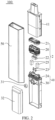
- FIG. 1 is a schematic diagram of an overall structure of an electronic atomization device according to an embodiment of this application
- FIG. 2 is a schematic diagram of an exploded structure of an electronic atomization device according to an embodiment of this application
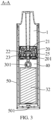
- FIG. 3 is a cross-sectional view of direction A-A of FIG. 1 .
- the electronic atomization device 100 includes a battery cell 32, a holder 40, and an atomization assembly 2.
- the battery cell 32 is assembled on the holder 40 and is configured to supply power to the atomization assembly 2, so that the atomization assembly 2 heats and atomizes an atomizable matrix.
- the electronic atomization device 100 further includes a liquid storage cavity housing 11 and a shell 50.
- a portion of the liquid storage cavity housing 11 is fixed in the shell 50 and cooperates with the atomization assembly 2 to form a liquid storage cavity 1, so as to accommodate the atomizable matrix through the liquid storage cavity 1.
- the atomization assembly 2 is arranged in the liquid storage cavity housing 11. Meanwhile, the battery cell 32 and the holder 40 are received together in the shell 50. It can be understood that after the assembling is completed, the product is non-removable and can be discarded immediately after use, making it a disposable product. Compared with a recyclable product, this product can simplify the assembled structure to an extent, which is conducive to mass production. Moreover, the product is easy to use and can effectively reduce the harm caused by the residues to a human body.
- the holder 40 includes a base body 24 and a mounting frame 30 arranged on one side of the base body 24.
- the base body 24 is connected to the liquid storage cavity housing 11 or the atomization assembly 2, is covered at an open end of the liquid storage cavity housing 11, and further cooperates with the liquid storage cavity housing 11 to fix the atomization assembly 2 in the liquid storage cavity housing 11.
- a mounting cavity is arranged in one end of the holder 40 facing away from the atomization assembly 2, namely, the mounting cavity is arranged in one end of the mounting frame 30 away from the base body 24.
- the battery cell 32 is at least partially assembled in the mounting cavity of the mounting frame 30 to fix the battery cell 32, thereby avoiding the problem of short circuit, open circuit, and the like between the battery cell 32 and the atomization assembly or another connector due to offset.
- the mounting cavity is an annular frame.
- the specific shape of the annular frame can be set according to the appearance of the battery cell 32.
- an air inlet gap is formed between the battery cell 32 and the inner wall of the shell 50. When a user inhales, an airflow can enter an air inlet channel 302 of the holder 40 along the air inlet gap, and then enter the atomization assembly 2 through the air inlet channel 302.
- the electronic atomization device further includes an airflow sensor 31.
- the airflow sensor 31 is arranged on the mounting frame 30.
- the airflow sensor 31 is configured to turn on the electronic atomization device 100 after sensing a change in the airflow or an air pressure, to turn on an atomization path, thereby turning on the electronic atomization device 100.
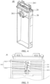
- FIG. 4 is a schematic structural diagram of one side of a holder according to an embodiment of this application
- FIG. 5 is a schematic structural diagram of the other side of a holder according to an embodiment of this application.
- the holder 40 includes a base body 24 and a mounting frame 30 arranged on one side of the base body 24.
- an accommodating cavity 301 for accommodating an airflow sensor 31 is arranged on one side of the mounting frame 30.
- the accommodating cavity 301 can be specifically a groove, and its shape and size can be matched according to the shape and size of the airflow sensor 31, without a limitation.
- the airflow sensor 31 can be specifically an airflow sensor, an air pressure sensor, a microphone, or another sensor that can sense a change in the airflow.
- the microphone is preferably used as the airflow sensor 31.
- an air inlet channel 302 is arranged at one end close to the base body 24.
- the air inlet channel 302 is communicated to an air inlet hole 241 on the base body 24, so that the airflow can smoothly enter the atomization assembly 2 through the air inlet channel 302 from the air inlet hole 241, to ensure an unblocked airflow.
- the mounting frame 30 is further provided with a detection air hole 303 that communicates the air inlet channel 302 with the accommodating cavity 301.
- the detection air hole 303 is specifically a through hole, so that when the airflow passes through the air inlet channel 302, the airflow sensor 31 in the accommodating cavity 301, facing away from the air inlet channel 302, on the mounting frame 30 can sense the change in the airflow through the detection air hole 303.
- the aperture size of the detection air hole 303 can be set in a matched manner according to the sensitivity of the airflow sensor 31, without a specific limitation.
- the mounting frame 30 of the holder 40 is arranged on one side of the base body 24; the airflow sensor 31 is arranged in the accommodating cavity 301 of the mounting frame 30; and the base body 24 and the mounting frame 30 are integrated. Therefore, the base body 24, the mounting frame 30, and the accommodating cavity 301 are connected without additional connectors, which simplifies the overall structure and manufacturing process of the electronic atomization device 100 and facilitates carrying and use.
- the air inlet channel 302 is arranged on the other side of the mounting frame 30 to communicate the air inlet hole 241 in the base body 24, and the air inlet channel 302 is communicated to the accommodating cavity 301 through the detection air hole 303, so that the airflow sensor 31 in the accommodating cavity 301 can sense the change in the airflow in the air inlet channel 302 through the detection air hole 303, thereby achieving electrical turning on and turning off of the electronic atomization device 100.
- a cut-off portion 3021 is further arranged in the air inlet channel 302.
- the detection air hole 303 is located on one side of the cut-off portion 3021 facing the air inlet hole 241. This can reduce the air inlet area of the airflow at the position of the cut-off portion 3021 in the air inlet channel 302, so that a negative pressure is easily generated in a cavity between the cut-off portion 3021 in the air inlet channel 302 and the air inlet hole 241 during inhalation. This makes it easier for the airflow sensor 31 to sense the negative pressure through the detection air hole 303 and be switched on, thereby achieving electrical turning on and turning off of the electronic atomization device 100.
- an air pressure difference in the cavity between the cut-off portion 3021 and the air inlet hole 241 changes greatly, so that the air pressure is more easily sensed by the airflow sensor 31, which effectively improves the sensitivity of the electronic atomization device 100. Even if the sensitivity of the airflow sensor 31 itself is low, the airflow sensor can reliably sense an inhalation action of a user, thereby effectively improving the reliability of the electronic atomization device 100.
- FIG. 6 is a cross-sectional view of direction B-B of FIG. 1 .
- the air inlet channel 302 on the mounting frame 30 is an air inlet groove.
- the inner wall of the shell 50 covers the air inlet groove and forms a cavity with the air inlet channel 302, so that the airflow can enter the atomization assembly 2 along the air inlet channel 302.
- a distance between the cut-off portion 3021 in the air inlet groove and the inner wall of the shell 50 ranges from 1.0 mm to 1.5 mm, which can be selected according to an actual need, to adjust the air inlet area at the position of the cut-off portion 3021 in the air inlet channel 302, thereby adjusting the sensitivity of the electronic atomization device 100 for sensing the airflow and the inhalation resistance during inhalation, so as to achieve the best effect during use of the electronic atomization device.
- the electronic atomization device 100 may further include a cover element (not shown).
- the cover element is attached to the air inlet groove, and a distance between the cut-off portion 3021 and the cover element ranges from 1.0 mm to 1.5 mm. It is easily understood that the cover element here serves as the shell, and the distance between the cut-off portion 3021 and the cover element can be adjusted by adjusting the distance between the cover element and the holder 40 or the thickness of the cover element, to adjust the air inlet area in the air inlet channel 302, so that the sensitivity of the electronic atomization device 100 is best.
- the air inlet channel 302 includes a first groove section 3022 and a second groove section 3023, namely, the air inlet groove includes the first groove section 3022 and the second groove section 3023, and the depth of the second groove section 3023 is greater than that of the first groove section 3022, so that the air inlet channel 302 is communicated to the air inlet hole 241.
- the cut-off portion 3021 is arranged in the first groove section 3022; the air inlet hole 241 on the base body 24 is communicated to the second groove section 3023, and the air inlet hole 241 faces the side wall of the connection between the second groove section 3023 and the first groove section 3022.
- the first groove section 3022, the second groove section 3023, and the air inlet hole 241 are communicated in sequence in an airflow direction, so that the airflow can flow to the air inlet hole 241 along the first groove section 3022 and the second groove section 3023 and smoothly enter the atomization space 25 in the atomization base 20.
- a plurality of transverse capillary grooves located on the two sides of the air inlet channel, are provided in the side wall of the mounting frame 30, and can be configured to absorb the aerosol condensate flowing to this position under an abnormal condition, ensuring that the electronic atomization device 100 does not leak liquid.
- FIG. 7 is a schematic structural diagram of a holder in a viewing angle according to an embodiment of the present disclosure.
- a recessed portion 304 is further arranged on one side, close to the shell 50, of the bottom of the mounting frame 30 of the holder 40.
- a gap is formed by spacing the recessed portion 304 is apart from an inhalation hole 501 of the shell 50, and the gap is communicated to the air inlet gap between the shell 50 and the battery cell 32, so that external air can enter through the gap during inhalation and enter the air inlet channel 302 on the mounting frame 30 along the air inlet gap between the battery cell 32 and the shell 50, thereby avoiding the following problem: the holder 40 blocks the inhalation hole 501 in the shell 50, so that the external air cannot enter the air inlet channel 302, and as a result, the electronic atomization device 100 cannot be turned on, and the aerosols cannot be inhaled by a user along with the airflow because of the blocked airflow.
- the shape and size of the recessed portion 304 can be set according to an actual need. Meanwhile, no specific limitation is made on the distance between the recessed portion 304 and the inhalation hole 501. Namely, no specific limitation is made on the size of the gap, as long as the external air can smoothly enter the air inlet channel during the inhalation by a user.
- one end of the holder 40 directly or indirectly presses against an atomization core 22 on the atomization base 20, so that the atomization core 22 is stably fixed on the atomization base 20, which can avoid the problem such as liquid leakage or circuit breakage caused by the looseness of the atomization core 22.
- the holder 40 is covered at one end of the atomization space 201, the aerosols formed in the atomization space 201 can enter a user with the inhalation of the airflow, thereby avoiding air leakage of the electronic atomization device 100 and preventing the problem of liquid leakage caused by the fact that the aerosol condensate stored in the liquid storage space 203 flows to another place, thus improving the assembling reliability of the electronic atomization device 100.
- the battery cell 32 is mounted at the other end of the holder 40 facing away from the atomization assembly 2 and is electrically connected to the atomization core 22, so that the battery cell 32 can supply power to the atomization core 22, thereby heating and atomizing the atomizable matrix.
- the battery cell 32 is mounted, the atomization core 22 is fixed, and the atomization space 201 and the liquid storage space 203 are sealed, so that the electronic atomization device 100 has a simplified assembled structure, is easy to assemble, and is conducive to production.
- the atomization assembly 2 is specifically configured to heat and atomize the atomizable matrix. Its specific structure and function are the same or similar to those in the following embodiments, and will not be described in detail here. Refer to the detailed description below for more information.
- FIG. 8 is a schematic diagram of an exploded structure of an electronic atomization device according to another embodiment of this application.
- the electronic atomization device 100 includes a main unit and an atomizer.
- the main unit is detachably connected to the atomizer and the main unit is configured to supply power to the atomizer.
- the main unit includes a mounting frame 30, an airflow sensor 31, and a battery cell 32.
- an accommodating cavity 301 is arranged on one side of the mounting frame 30 to accommodate the airflow sensor 31.
- the battery cell 32 is assembled on the mounting frame 30 and is electrically connected to the airflow sensor 31 and an electrode 23.
- the mounting frame 30 is the mounting frame 30 involved in the above embodiment and can achieve the same or similar technical effects. Refer to the above text for its specific structure and function, which will not be elaborated here.
- the atomizer includes a liquid storage tank 60 and an atomization assembly 2.
- the liquid storage tank 60 is configured to receive an atomizable matrix.
- the atomization assembly 2 is arranged in the liquid storage tank 60 and is communicated to the liquid storage tank 60, so that the atomizable matrix can flow to an atomization core 22 of the atomization assembly 2 for being heated and atomized.
- FIG. 9 is a schematic diagram of an exploded structure of an atomization assembly according to an embodiment of this application.
- the atomization assembly 2 includes a seal member 21, an atomization base 20, an atomization core 22, an electrode 23, a base 27, a liquid storage structure 25, and a liquid accumulation structure 26.
- the electrode 23 includes two electrodes 23 with opposite polarities. One end of each of the two electrodes 23 is electrically connected to the atomization core 22, and the other end is electrically connected to the positive and negative electrodes of the main unit to supply power to the atomization core 22 when powered on.
- the atomization core 22 is arranged in the atomization space 201 of the atomization base 20, and the seal member 21 covers the end portion of the atomization base 20.
- the base 27 is connected to the bottom of the atomization base 20, and the base 27 is configured to directly or indirectly press against the atomization core 22 in the atomization base 20, and covers one end of the atomization space 201 and one end of the liquid storage space 203, so that the atomization core 22 is stably fixed on the atomization base 20, which can avoid the problem such as liquid leakage or circuit breakage caused by the looseness of the atomization core 22.
- each electrode 23 is of a cylindrical thimble structure.
- the base 27 covers one end of the atomization base 20 to form the atomization space 203, and the atomization core 22 can be clamped in the atomization space 203 by the base 27 and/or the atomization base 20, and is pressed by one end of the base 27 close to the atomization space 203, so that the atomization core 22 is stably fixed in the atomization space 203.
- the base 27 is covered at one end of the atomization space 201 and one end of the liquid storage space 203, the aerosols can enter a user with the inhalation of the airflow, thereby avoiding air leakage of the electronic atomization device 100 and preventing the problem of liquid leakage caused by the fact that the aerosol condensate stored in the liquid storage space 203 flows to another place.
- a base body 24 on the holder 40 has the structure and function that are the same or similar to the base 27 in this embodiment, and can achieve the same technical effects.
- the base body 24 is also similar to the structure and function of the base 27 involved in the following embodiment, and can achieve the same technical effects. It can be understood that the base body 24 in the above embodiment is equivalent to the base 27 involved in other embodiments of this application.
- the main unit includes a mounting frame 30, an airflow sensor 31, and a battery cell 32.
- an accommodating cavity 301 is arranged on one side of the mounting frame 30 to accommodate the airflow sensor 31.
- the battery cell 32 is assembled on the mounting frame 30 and is electrically connected to the airflow sensor 31 and an electrode 23.
- the mounting frame 30 is the mounting frame 30 involved above and can achieve the same or similar technical effects. Refer to the above text for its specific structure and function, which will not be elaborated here.
- FIG. 10 is a cross-sectional view of an atomization assembly according to an embodiment of this application; and FIG. 11 is a schematic structural diagram of an atomization base according to an embodiment of this application.
- an atomization assembly 2 is provided.
- the atomization assembly 2 includes an atomization base 20 and a liquid storage structure 25.
- the atomization base 20 is provided with an atomization space 201, a condensation slot 202, and a liquid storage space 203.
- the condensation slot 202 is arranged on the outer peripheral surface of the atomization base; and the condensation slot 202 is respectively communicated to the atomization space 201 and the liquid storage space 203 in a circumferential direction of the atomization base 20.
- the condensation slot 202 is specifically configured to absorb aerosol condensate formed outside the atomization space 201.
- the condensation slot 202 is communicated to the liquid storage space 203, so that the aerosol condensate absorbed in the condensation slot 202 can enter the liquid storage space 203 for being stored, thereby separating condensation and storage, and avoiding the problem of blockage and liquid leakage caused by a large amount of condensate accumulated in the condensation slot due to a large atomization amount.
- the liquid storage space 203 is arranged at one end of the atomization base 20 in its radial direction
- the condensation slot 202 is arranged around the liquid storage space 203 and the atomization space 201 in the circumferential direction of the atomization base 20 on the outer peripheral surface of the atomization base 20, to increase the capacity of the condensation slot 202 and enlarge the area in contact with the aerosols, thereby maximizing the absorption of the aerosol condensate and enhancing the liquid leakage prevention effect of the electronic atomization device 100.
- the condensation slot 202 is respectively communicated to the atomization space 201 and the liquid storage space 203 in the circumferential direction of the atomization base 20, namely, one end of the condensation slot 202 is communicated to the atomization space 201 and the other end is communicated to the liquid storage space 203.
- the condensation slot 202 extends in the circumferential direction of the atomization base 20 and surrounds a portion of the atomization space 201 and a portion of the liquid storage space 203. In this way, a region is reserved on the outer peripheral surface of the atomization base 20 for the design of other structures.
- a partition wall 231 is provided between the atomization space 201 and the liquid storage space 203, so that the atomization space 201 and the liquid storage space 203 are separated by the partition wall 231, and the liquid storage space 203 and the atomization space 201 are two independent and isolated spaces. Even if the inhalation force on the atomization space 201 is increased, the aerosol condensate stored in the liquid storage space 203 will not be inhaled into the mouth of a user.
- the liquid storage structure 25 is arranged in the liquid storage space 203.
- the liquid storage structure 25 is specifically configured to store the liquid collected by the condensation slot 202, and has high collection ability for the liquid, which can avoid the stored liquid from leaking to other outlets. It can further prevent liquid leakage of an electronic atomization device with high capacity or a large atomization amount, and prevent the problem of secondary liquid leakage caused by the fact that the aerosol condensate flows from the liquid storage space 203 to another place.
- the aerosols are formed in the atomization space 201 of the atomization base 20. Therefore, after leaving the atomization space 201 along with the airflow, the aerosols and water vapor in the atomization space 201 may be in contact with the atomization base 20 or an airflow corner and possibly congealed into condensate.
- a condensation slot 202 is provided on the outer peripheral surface of the atomization base 20, and the condensation slot 202 is communicated to the atomization space 201, so that the condensate is further absorbed into the condensation slot 202. Meanwhile, the condensation slot 202 is communicated to the liquid storage space 203, the condensate can enter the liquid storage space 203 through the condensation slot 202 and be stored.
- a liquid storage structure 25 is arranged in the liquid storage space 203, so that the condensate and water vapor can be gathered in the liquid storage structure 25.
- the liquid storage space 203 is isolated from the atomization space 201, even if the inhalation force on the atomization space 201 is increased, the condensate stored in the liquid storage structure 25 will not be inhaled into the mouth of a user.
- the liquid storage structure 25 in the liquid storage space 203 has high collection ability on the liquid, which can avoid the leakage of the stored liquid to other outlets and effectively prevent liquid leakage of the electronic atomization device with high capacity or a large atomization amount.
- the liquid storage structure 25 is a liquid storage element and is accommodated in the liquid storage space 203.
- a material of the liquid storage element may be specifically fibers, foam, sponge, foam ceramic, soft rubber, silica gel resin, or another material having good liquid absorption and not easily corroded by an atomizable matrix, to absorb the aerosol condensate collected in the condensation slot 202, maintain the stability of its liquid absorption performance, and avoid secondary leakage of the aerosol condensate.
- the liquid storage structure 25 is a capillary micro groove(s); and the capillary micro groove(s) is provided on a wall of the liquid storage space 203 and is communicated to the condensation slot 202.
- the capillary micro groove(s) is provided in the inner side wall of the liquid storage space 203.
- the direction, width, and depth of the capillary micro groove(s) can be set according to an actual need.
- the capillary micro groove(s) can be curved, straight, horizontal, vertical, or in other angular directions, as long as the capillary micro groove(s) can absorb the aerosol condensate collected in the condensation slot 202 through the capillary effect and store the aerosol condensate in the liquid storage space 203. No specific limitation is made here.
- the liquid storage structure 25 may further include a liquid storage element and a capillary micro groove(s). At least a portion of the capillary micro groove(s) is communicated to the liquid storage element, so that after the capillary micro groove(s) absorbs excess aerosol condensate, the excess aerosol condensate flows to the liquid storage element for being stored under the capillary action. This further avoids the problem of liquid leakage or inhalation of the aerosol condensate to a user end because the aerosol condensate is blocked in the condensation slot 202.
- the atomization base 20 has two liquid storage spaces 203.
- the two liquid storage spaces 203 are arranged at the two opposite ends of the atomization base 20 in a radial direction of the atomization base 20.
- the atomization space 201 is located between the two liquid storage spaces 203.
- the atomization space 201 is isolated from the two liquid storage spaces 203 by two partition walls 231.
- Liquid storage structures 25 are arranged in the two liquid storage spaces 203. Namely, an internal space of the atomization base 20 is separated into three independent spaces by the two partition walls 231 that are spaced apart from each other.
- the middle space is the atomization space 201, and the spaces at the two ends are the liquid storage spaces 203, thereby separating the atomization space 201 from the liquid storage spaces 203.
- the structure of the atomization base 20 is more symmetrical, and the force on all parts is balanced.
- the aerosol condensate can be absorbed and stored to a large extent, which prevents liquid leakage of the electronic atomization device 100.
- the liquid storage space 203 may alternatively be arranged on the outer side of the side wall of the atomization base 20.
- the liquid storage space 203 is defined between the outer side wall of the atomization base 20 and the side wall of a liquid storage tank 60.
- a partition wall 231 is arranged on the inner wall of the atomization base 20. The partition wall 231 separates the atomization space 201 from the liquid storage space 203, so that the aerosol condensate stored in the liquid storage structure 25 is separated from the atomization space 201 and will not be inhaled to a user end.
- FIG. 12 is a diagram of a direction of aerosol condensate according to an embodiment of this application.
- at least one through hole 204 is provided in the side wall of the atomization base 20.
- the through hole 204 communicates the liquid storage space 203 to the condensation slot 202, and the through hole 204 is a capillary hole.
- formed aerosols are cooled and condensed, thereby forming aerosol condensate.
- the aerosol condensate is absorbed by the condensation slot 202 communicated to the atomization space 201, flows to the through hole 204 under the capillary action, and then flows through the through hole 204 to the liquid storage space 203 under the capillary action again for being absorbed by the liquid storage structure 25 and stored in the liquid storage structure 25.
- At least two condensation slots 202 are provided on the side wall of the atomization base 20; the through hole 204 is provided in a spacing wall between two adjacent condensation slots 202; and the through hole 204 communicates the two adjacent condensation slots 202.
- the plurality of condensation slots 202 can simultaneously absorb the aerosol condensate, and the through hole 204 is provided in the spacing wall between two adjacent condensation slots 202 to communicate the two adjacent condensation slots 202. This allows the aerosol condensate collected in the two condensation slots 202 to enter the liquid storage space 203 through the through hole 204. With the same absorption and storage effects, this setting can further reduce the number of the through hole 204 and save process steps.
- the through hole 204 may alternatively be provided in the condensation slot 202, so that the aerosol condensate collected in the condensation slot 202 enters the liquid storage space 203 through the through hole 204 and is then stored in a condensation structure.
- the number and specific arrangement position of the through hole 204 that communicates the condensation slot 202 to the liquid storage space 203 can be set according to an actual need, as long as the number and the setting position can allow the aerosol condensate temporarily collected in the condensation slot 202 to enter the liquid storage space 203 under the capillary action and be stored in the liquid storage structure 25.
- At least one flowing opening 205 is further provided in the side wall of the atomization base 20; and the flowing opening 205 is communicated to the atomization space 201 and the condensation slot 202.
- An aerial fog outlet 207 is provided in the other end of the atomization base 20; the atomization base 20 is further provided with an aerial fog flow channel; and the aerial fog flow channel is communicated to the flowing opening 205 and the aerial fog outlet 207.
- the aerosols In the process that the aerosols leave the atomization space 201 along with the airflow from the flowing opening 205 and enter the aerial fog flow channel, the aerosols will be condensed due to a temperature drop, thereby forming the aerosol condensate.
- the condensation slot 202 As the condensation slot 202 is communicated to the atomization space 201 and the aerial fog flow channel, the aerosol condensate is attached into the condensation slot 202. Under the capillary action, the aerosol condensate flows along the condensation slot 202 to the through hole 204. Under the surface tension of the liquid and the capillary action, the liquid flows through the through hole 204 to the liquid storage space 203 and is stored in the liquid storage structure 25, thus avoiding the problem of backflow of the aerosol condensate.
- the aerial fog flow channel is further provided with a flow guiding portion 2061 and is configured to guide the condensed atomizable matrix to the atomization core 22 arranged in the atomization space 201. This not only further reduces the possibility that the condensed atomizable matrix is inhaled to a client, but also can achieve secondary atomization on the condensed atomizable matrix and improve the utilization rate of the atomizable matrix.
- the flow guiding portion 2061 includes a plurality of flow guiding columns which are spaced apart from one another; the end portions of the flow guiding columns extend to the atomization space 201; and a flow guiding gap formed by the end portions of two adjacent flow guiding columns faces the side wall of the atomization core 22.
- the aerosol condensate attached to the side wall of the aerial fog flow channel flows along the flow guiding portion 2061 to the end portions of the flow guiding columns, and then flows through the flow guiding gaps at the end portions to the side wall of the atomization core 22, thereby achieving secondary atomization on the aerosol condensate and further reducing the possibility of inhalation to a client and the occurrence rate of liquid leakage.
- the flowing openings 205 and the aerial fog flow channels are arranged in the two sides of the atomization base 20.
- the condensation slots 202 and the flow guiding portions 2061 are arranged on the two sides too, to enlarge a contact area with the aerosol condensate.
- the condensation slots 202 are arranged in the two sides of the aerial fog flow channel to further enlarge the contact area with the aerosol condensate, so that the aerosol condensate will not be inhaled or leak, and will not flow to the outside of the battery cell 32 or the device.
- a first liquid inlet hole 209 is further provided in one end of the atomization base 20 close to the liquid storage tank 60.
- One end of the first liquid inlet hole 209 is communicated to the liquid storage tank 60, and the other end is communicated to the atomization core 22, so that the atomizable matrix in the liquid storage tank 60 flows to the atomization core 22 through the first liquid inlet hole 209, to enable the atomization core 22 to heat and atomize the atomizable matrix.
- the atomization base 20 is provided with two liquid inlet holes 209 respectively located on two opposite sides of the aerial fog outlet 207.
- the atomizable matrix flows through the two first liquid inlet holes 209 to the atomization core 22, to provide sufficient atomizable matrix for the atomization core 22, thereby ensuring a sufficient atomization amount.
- a positioning slot 208 located on one side of each first liquid inlet hole 209 facing away from the aerial fog outlet 207 is further provided in the atomization base 20, and the positioning slot 208 is communicated to the first liquid inlet hole 209, so that the atomizable matrix in the liquid storage tank 60 can further flow through the positioning slot 208 and the first liquid inlet hole 209 to the atomization core 22, thereby heating and atomizing the atomizable matrix.
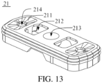
- FIG. 13 is a schematic structural diagram of a seal member 21 according to an embodiment of this application.
- the atomization assembly 2 further includes a seal member 21 covering the end portion of the atomization base 20.
- the seal member 21 is provided with a liquid collection slot 211, a liquid inlet 212, and an aerial fog port 213.
- the aerial fog port 213 is communicated to the aerial fog outlet 207 on the atomization base 20, and the liquid inlet 212 is communicated to the first liquid inlet hole 209.
- a second liquid inlet hole 214 is provided in the bottom of the liquid collection slot 211, and the second liquid inlet hole 214 is communicated to the positioning slot 208 of the atomization base 20.
- the liquid collection slot 211 and the liquid inlet 212 are respectively communicated to the liquid storage tank 60, so that the atomizable matrix in the liquid storage tank 60 can flow into the atomization core 22 in the atomization base 20 from the liquid collection slot 211 and/or the liquid inlet 212.
- the liquid collection slot 211 is of a funnel-shaped structure, so that the remaining atomizable matrix in the liquid storage tank 60 flows through the funnel-shaped liquid collection slot 211 to the second liquid inlet hole 214, and then flows through the positioning slot 208 to the atomization core 22 in the atomization base 20 for being heated and atomized, thereby reducing the remaining atomizable matrix in the liquid storage tank 60.
- the atomization assembly 2 further includes a liquid accumulation structure 26.
- the liquid accumulation structure 26 is configured to receive the aerosol condensate in the liquid storage structure 25.
- the liquid accumulation structure 26 is arranged on the base 27 and is covered at one end of the liquid storage space 203.
- the liquid accumulation structure 26 and the liquid storage structure 25 are arranged radially opposite to each other in a radial direction of the atomization assembly 2.
- the liquid accumulation structure 26 can be communicated to the liquid storage structure 25, to absorb the liquid in the liquid storage structure 25 more easily and timely, so that the liquid storage structure 25 can continue to absorb the liquid collected by the condensation slot 202, to improve the liquid storage capacity of the atomization assembly 2.
- the base 27 is provided with an accommodating slot 242; the liquid accumulation structure 26 is arranged in the accommodating slot 242; the liquid accumulation structure 26 is a liquid accumulation element, similar to the liquid storage element.
- a material of the liquid accumulation element can be fibers, foam, sponge, foam ceramic, soft rubber, silica gel resin and another material that has good absorbency and is not easily corroded by the atomizable matrix, to further receive the aerosol condensate in the liquid storage structure 25.
- the liquid accumulation structure 26 may be a liquid accumulation slot for receiving and storing the aerosol condensate. It is easily understood the shape and size of the liquid accumulation slot can be set according to a specific need, as long as the liquid accumulation slot can store liquid and ensure no liquid leakage.
Landscapes
- Special Spraying Apparatus (AREA)
Abstract
Description
- This application relates to the field of electronic atomization, and in particular, to an atomization assembly, an atomizer, and an electronic atomization device.
- An electronic atomization device is configured to: form aerosols by heating and atomizing an atomizable matrix, and then transport the aerosols to a user end through an airflow channel.
- To meet the needs of a user, the existing electronic atomization device generally tends to have high capacity and a large number of puffs, which means that the atomizable matrix has higher capacity and a larger atomization amount. However, with the increase of the capacity and the atomization amount, after lots of aerosols leave an atomization space and enter an aerial fog channel, the temperature of the aerosols gradually decreases, which can easily lead to the problem of an increase in the aerosol condensation in the aerial fog channel. This can easily cause aerosol condensate to be accumulated and inhaled into the mouth of the user, as well as the problem of liquid leakage caused by the aerosol condensate flowing out of the electronic atomization device through the aerial fog channel or another outlet.
- This application provides an atomization assembly, an atomizer, and an electronic atomization device, and aims to solve the problem of liquid leakage easily caused by an electronic atomization device with high capacity or a large atomization amount.
- To solve the foregoing technical problem, a first technical solution used in this application is as follows: an atomization assembly is provided. The atomization assembly includes: an atomization base and a liquid storage structure; the atomization base is provided with an atomization space, a condensation slot, and a liquid storage space; the condensation slot is arranged at an outer periphery of the atomization base; the atomization space and the liquid storage space are separated by a partition wall on the atomization base; the liquid storage structure is arranged in the liquid storage space to store liquid collected in the condensation slot; and the liquid storage space is communicated to the atomization space through the condensation slot.
- In some embodiments, the liquid storage structure includes a liquid storage element, and the liquid storage element is accommodated in the liquid storage space; or the liquid storage structure includes a capillary micro groove; and the capillary micro groove is provided on a wall of the liquid storage space and is communicated to the condensation slot.
- In some embodiments, the atomization space is arranged at one end of the atomization base; the condensation slot is arranged on an outer peripheral surface of the atomization base; the condensation slot is respectively communicated to the atomization space and the liquid storage space in a circumferential direction of the atomization base; or the liquid storage space is arranged at one end of the atomization base; and the condensation slot is arranged around the liquid storage space and the atomization space.
- In some embodiments, the liquid storage space is formed by cooperation between the partition wall and an inner side of a side wall of the atomization base; at least one through hole is provided in the side wall of the atomization base; and the at least one through hole is communicated to the liquid storage space and the condensation slot.
- In some embodiments, the at least one through hole is a capillary hole.
- In some embodiments, at least two condensation slots are provided on an outer side of the side wall of the atomization base; the at least one through hole is provided in a spacing wall between two adjacent condensation slots of the at least two condensation slots; and the at least one through hole communicates the two adjacent condensation slots.
- In some embodiments, at least one flowing opening is further provided on the side wall of the atomization base; the at least one flowing opening is communicated to the atomization space and the condensation slot; an aerial fog outlet is provided in an other end of the atomization base; the atomization base is provided with an aerial fog flow channel; the aerial fog flow channel is communicated to the at least one flowing opening and the aerial fog outlet; the aerial fog flow channel is provided with a flow guiding portion; and the flow guiding portion is configured to guide a condensed atomizable matrix to an atomization core arranged in the atomization space.
- In some embodiments, the flow guiding portion includes a plurality of flow guiding columns spaced apart from one another; the end portions of the flow guiding columns extend to the atomization space; and a flow guiding gap formed by the end portions of two adjacent flow guiding columns faces the side wall of the atomization core.
- In some embodiments, a first liquid inlet hole and a positioning slot are arranged at an other end of the atomization base; the positioning slot is communicated to the first liquid inlet hole; the atomization assembly includes a seal member; a liquid collection slot is provided on the seal member; a second liquid inlet hole is provided at a bottom of the liquid collection slot; and the seal member is covered at an end portion of the atomization base so as to make the second liquid inlet hole be communicated to the positioning slot.
- In some embodiments, the atomization assembly further includes a base; a liquid accumulation structure is arranged on the base; the base is connected to the atomization base so as to cover one end of the liquid storage space with the liquid accumulation structure.
- In some embodiments, the base is provided with an accommodating slot; the liquid accumulation structure includes a liquid accumulation element; and the liquid accumulation element is arranged in the accommodating slot; or the liquid accumulation structure includes a liquid accumulation slot.
- To solve the foregoing technical problem, a second technical solution used in this application is as follows: an atomizer is provided. The atomizer includes any one of the above atomization assemblies.
- To solve the foregoing technical problems, a third technical solution used in this application is as follows: an electronic atomization device is provided. The electronic atomization device includes a main unit and the above atomizer. The main unit is detachably connected to the atomizer and configured to supply power to the atomizer; or the electronic atomization device includes a battery cell, a shell, and any one of the above atomization assemblies; the base is connected to the atomization base; and the battery cell is assembled on the base and configured to supply power to the atomization core on the atomization base.
- According to the atomization assembly provided in this application, the condensation slot at the outer periphery of the atomization base is communicated to the atomization space and the liquid storage space, so that aerosol condensate formed outside the atomization space is absorbed in the condensation slot and can enter the liquid storage space through the condensation slot. This collects the aerosol condensate in the condensation slot and stores the aerosol condensate in the liquid storage space, thereby separating condensation and storage, and avoiding the problem of blockage and liquid leakage caused by a large amount of condensate accumulated in the condensation slot due to a large atomization amount. Meanwhile, by spacing the liquid storage space on the atomization base from the atomization space by the partition wall, even if the inhalation force on the atomization space is increased, the condense stored in the liquid storage structure will not be sucked into the mouth of a user. Moreover, by the arrangement of the liquid storage structure in the liquid storage space, high collection ability is achieved on liquid, which can avoid the leakage of the stored liquid to other outlets and effectively prevent liquid leakage of the electronic atomization device with high capacity or a large atomization amount.
-
-
FIG. 1 is a schematic diagram of an overall structure of an electronic atomization device according to an embodiment of this application. -
FIG. 2 is a schematic diagram of an exploded structure of an electronic atomization device according to an embodiment of this application. -
FIG. 3 is a cross-sectional view of direction A-A ofFIG. 1 . -
FIG. 4 is a schematic structural diagram of a holder viewed from one side according to an embodiment of this application. -
FIG. 5 is a schematic, partial structural diagram of a holder viewed from the other side according to an embodiment of this application. -
FIG. 6 is a cross-sectional view of direction B-B ofFIG. 1 . -
FIG. 7 is a schematic structural diagram of a holder in a viewing angle according to an embodiment of the present disclosure. -
FIG. 8 is a schematic diagram of an exploded structure of an electronic atomization device according to another embodiment of this application. -
FIG. 9 is a schematic diagram of an exploded structure of an atomization assembly according to an embodiment of this application. -
FIG. 10 is a cross-sectional view of an atomization assembly according to an embodiment of this application. -
FIG. 11 is a schematic structural diagram of an atomization base according to an embodiment of this application. -
FIG. 12 is a diagram of a direction of aerosol condensate according to an embodiment of this application. and -
FIG. 13 is a schematic structural diagram of a seal member according to an embodiment of this application. - The solutions of the embodiments of this application will be described in detail below in conjunction with the accompanying drawings of this specification.
- In the following description, for the purpose of illustration rather than limitation, specific details such as the specific system structure, interface, technology or the like are proposed to thoroughly understand this application.
- The technical solutions in embodiments of this application are clearly and completely described in the following with reference to the accompanying drawings in the embodiments of this application. Apparently, the described embodiments are merely some rather than all of the embodiments of this application. All other embodiments obtained by a person of ordinary skill in the art based on the embodiments of this application without creative efforts shall fall within the protection scope of this application.
- The terms "first", "second", and "third" in this application are merely intended for a purpose of description, and shall not be understood as indicating or implying an indication or implication of relative importance or implicitly indicating the number of indicated technical features. Therefore, features defining "first", "second", and "third" can explicitly or implicitly include at least one of the features. In the description of this application, "plurality" means at least two, such as two and three unless it is specifically defined otherwise. All directional indications (such as up, down, left, right, front, back...) involved in the embodiments of this application are only used to explain the relative positional relationship, motion states, and the like between various components in specific postures (as shown in the accompanying drawings). If the specific postures change, the directional indications also change correspondingly. In addition, the term "include", "has", and any variant thereof are intended to cover a non-exclusive inclusion. For example, a process, method, system, product, or device that includes a series of steps or units is not limited to the listed steps or units; and instead, further optionally includes a step or unit that is not listed, or further optionally includes another step or unit that is intrinsic to the process, method, product, or device.
- The term "embodiment" mentioned in the specification means that particular features, structures, or characteristics described with reference to the embodiment may be included in at least one embodiment of this application. The appearance of this phrase in various places in the specification does not necessarily refer to the same embodiment, nor is it a separate or alternative embodiment that is mutually exclusive with other embodiments. It is explicitly and implicitly understood by those skilled in the art that the embodiments described herein may be combined with other embodiments.
- This application will be explained in detail below in conjunction with the accompanying drawings and embodiments.
- In a specific embodiment of this application, an electronic atomization device is provided. The electronic atomization device is configured to heat and atomize an atomizable matrix when powered on, to generate aerosols for use by a user. The electronic atomization device is applicable to different fields, such as medical treatment, beauty treatment, or recreational smoking, etc. The atomizable matrix can be an oily matter composed of glycerol, propylene glycol, essence, flavor and the like, or liquid formed by dispersing some drugs in a solvent.
- Referring to
FIG. 1 to FIG. 3 ,FIG. 1 is a schematic diagram of an overall structure of an electronic atomization device according to an embodiment of this application;FIG. 2 is a schematic diagram of an exploded structure of an electronic atomization device according to an embodiment of this application; andFIG. 3 is a cross-sectional view of direction A-A ofFIG. 1 . - In this embodiment, the
electronic atomization device 100 includes abattery cell 32, aholder 40, and anatomization assembly 2. Thebattery cell 32 is assembled on theholder 40 and is configured to supply power to theatomization assembly 2, so that theatomization assembly 2 heats and atomizes an atomizable matrix. - Further, the
electronic atomization device 100 further includes a liquidstorage cavity housing 11 and ashell 50. A portion of the liquidstorage cavity housing 11 is fixed in theshell 50 and cooperates with theatomization assembly 2 to form a liquid storage cavity 1, so as to accommodate the atomizable matrix through the liquid storage cavity 1. Theatomization assembly 2 is arranged in the liquidstorage cavity housing 11. Meanwhile, thebattery cell 32 and theholder 40 are received together in theshell 50. It can be understood that after the assembling is completed, the product is non-removable and can be discarded immediately after use, making it a disposable product. Compared with a recyclable product, this product can simplify the assembled structure to an extent, which is conducive to mass production. Moreover, the product is easy to use and can effectively reduce the harm caused by the residues to a human body. - In this embodiment, the
holder 40 includes abase body 24 and a mountingframe 30 arranged on one side of thebase body 24. Thebase body 24 is connected to the liquidstorage cavity housing 11 or theatomization assembly 2, is covered at an open end of the liquidstorage cavity housing 11, and further cooperates with the liquidstorage cavity housing 11 to fix theatomization assembly 2 in the liquidstorage cavity housing 11. Specifically, a mounting cavity is arranged in one end of theholder 40 facing away from theatomization assembly 2, namely, the mounting cavity is arranged in one end of the mountingframe 30 away from thebase body 24. Thebattery cell 32 is at least partially assembled in the mounting cavity of the mountingframe 30 to fix thebattery cell 32, thereby avoiding the problem of short circuit, open circuit, and the like between thebattery cell 32 and the atomization assembly or another connector due to offset. In this embodiment, the mounting cavity is an annular frame. The specific shape of the annular frame can be set according to the appearance of thebattery cell 32. Moreover, an air inlet gap is formed between thebattery cell 32 and the inner wall of theshell 50. When a user inhales, an airflow can enter anair inlet channel 302 of theholder 40 along the air inlet gap, and then enter theatomization assembly 2 through theair inlet channel 302. Specifically, the electronic atomization device further includes anairflow sensor 31. Theairflow sensor 31 is arranged on the mountingframe 30. Theairflow sensor 31 is configured to turn on theelectronic atomization device 100 after sensing a change in the airflow or an air pressure, to turn on an atomization path, thereby turning on theelectronic atomization device 100. - Specifically, referring to
FIG. 4 and FIG. 5, FIG. 4 is a schematic structural diagram of one side of a holder according to an embodiment of this application; andFIG. 5 is a schematic structural diagram of the other side of a holder according to an embodiment of this application. In this embodiment, theholder 40 includes abase body 24 and a mountingframe 30 arranged on one side of thebase body 24. Specifically, anaccommodating cavity 301 for accommodating anairflow sensor 31 is arranged on one side of the mountingframe 30. Theaccommodating cavity 301 can be specifically a groove, and its shape and size can be matched according to the shape and size of theairflow sensor 31, without a limitation. Theairflow sensor 31 can be specifically an airflow sensor, an air pressure sensor, a microphone, or another sensor that can sense a change in the airflow. In this embodiment, the microphone is preferably used as theairflow sensor 31. On the other side of the mountingframe 30, anair inlet channel 302 is arranged at one end close to thebase body 24. Theair inlet channel 302 is communicated to anair inlet hole 241 on thebase body 24, so that the airflow can smoothly enter theatomization assembly 2 through theair inlet channel 302 from theair inlet hole 241, to ensure an unblocked airflow. Further, the mountingframe 30 is further provided with adetection air hole 303 that communicates theair inlet channel 302 with theaccommodating cavity 301. Thedetection air hole 303 is specifically a through hole, so that when the airflow passes through theair inlet channel 302, theairflow sensor 31 in theaccommodating cavity 301, facing away from theair inlet channel 302, on the mountingframe 30 can sense the change in the airflow through thedetection air hole 303. The aperture size of thedetection air hole 303 can be set in a matched manner according to the sensitivity of theairflow sensor 31, without a specific limitation. - According to the
electronic atomization device 100 provided in this embodiment, by the arrangement of theholder 40 and theairflow sensor 31, the mountingframe 30 of theholder 40 is arranged on one side of thebase body 24; theairflow sensor 31 is arranged in theaccommodating cavity 301 of the mountingframe 30; and thebase body 24 and the mountingframe 30 are integrated. Therefore, thebase body 24, the mountingframe 30, and theaccommodating cavity 301 are connected without additional connectors, which simplifies the overall structure and manufacturing process of theelectronic atomization device 100 and facilitates carrying and use. Meanwhile, theair inlet channel 302 is arranged on the other side of the mountingframe 30 to communicate theair inlet hole 241 in thebase body 24, and theair inlet channel 302 is communicated to theaccommodating cavity 301 through thedetection air hole 303, so that theairflow sensor 31 in theaccommodating cavity 301 can sense the change in the airflow in theair inlet channel 302 through thedetection air hole 303, thereby achieving electrical turning on and turning off of theelectronic atomization device 100. - Further, a cut-
off portion 3021 is further arranged in theair inlet channel 302. Thedetection air hole 303 is located on one side of the cut-off portion 3021 facing theair inlet hole 241. This can reduce the air inlet area of the airflow at the position of the cut-off portion 3021 in theair inlet channel 302, so that a negative pressure is easily generated in a cavity between the cut-off portion 3021 in theair inlet channel 302 and theair inlet hole 241 during inhalation. This makes it easier for theairflow sensor 31 to sense the negative pressure through thedetection air hole 303 and be switched on, thereby achieving electrical turning on and turning off of theelectronic atomization device 100. Furthermore, at the beginning of inhalation or at the stop of inhalation, an air pressure difference in the cavity between the cut-off portion 3021 and theair inlet hole 241 changes greatly, so that the air pressure is more easily sensed by theairflow sensor 31, which effectively improves the sensitivity of theelectronic atomization device 100. Even if the sensitivity of theairflow sensor 31 itself is low, the airflow sensor can reliably sense an inhalation action of a user, thereby effectively improving the reliability of theelectronic atomization device 100. - Referring to
FIG. 5 andFIG. 6, FIG. 6 is a cross-sectional view of direction B-B ofFIG. 1 . Specifically, theair inlet channel 302 on the mountingframe 30 is an air inlet groove. When theholder 40 is arranged in theshell 50, the inner wall of theshell 50 covers the air inlet groove and forms a cavity with theair inlet channel 302, so that the airflow can enter theatomization assembly 2 along theair inlet channel 302. A distance between the cut-off portion 3021 in the air inlet groove and the inner wall of theshell 50 ranges from 1.0 mm to 1.5 mm, which can be selected according to an actual need, to adjust the air inlet area at the position of the cut-off portion 3021 in theair inlet channel 302, thereby adjusting the sensitivity of theelectronic atomization device 100 for sensing the airflow and the inhalation resistance during inhalation, so as to achieve the best effect during use of the electronic atomization device. - In another embodiment, the
electronic atomization device 100 may further include a cover element (not shown). The cover element is attached to the air inlet groove, and a distance between the cut-off portion 3021 and the cover element ranges from 1.0 mm to 1.5 mm. It is easily understood that the cover element here serves as the shell, and the distance between the cut-off portion 3021 and the cover element can be adjusted by adjusting the distance between the cover element and theholder 40 or the thickness of the cover element, to adjust the air inlet area in theair inlet channel 302, so that the sensitivity of theelectronic atomization device 100 is best. - Referring to
FIG. 5 again, in this embodiment, theair inlet channel 302 includes afirst groove section 3022 and a second groove section 3023, namely, the air inlet groove includes thefirst groove section 3022 and the second groove section 3023, and the depth of the second groove section 3023 is greater than that of thefirst groove section 3022, so that theair inlet channel 302 is communicated to theair inlet hole 241. Specifically, the cut-off portion 3021 is arranged in thefirst groove section 3022; theair inlet hole 241 on thebase body 24 is communicated to the second groove section 3023, and theair inlet hole 241 faces the side wall of the connection between the second groove section 3023 and thefirst groove section 3022. Therefore, after leaked liquid flows into theair inlet hole 241, the side wall at this position has a catching effect on the leaked liquid, which can prevent the leaked liquid from directly leaking to thedetection air hole 303, causing thedetection air hole 303 to be blocked and affecting theairflow sensor 31 to sense the change in the airflow. Thefirst groove section 3022, the second groove section 3023, and theair inlet hole 241 are communicated in sequence in an airflow direction, so that the airflow can flow to theair inlet hole 241 along thefirst groove section 3022 and the second groove section 3023 and smoothly enter theatomization space 25 in theatomization base 20. - Further, a plurality of transverse capillary grooves, located on the two sides of the air inlet channel, are provided in the side wall of the mounting
frame 30, and can be configured to absorb the aerosol condensate flowing to this position under an abnormal condition, ensuring that theelectronic atomization device 100 does not leak liquid. - Referring to
FIG. 2 andFIG. 7, FIG. 7 is a schematic structural diagram of a holder in a viewing angle according to an embodiment of the present disclosure. In this embodiment, a recessed portion 304 is further arranged on one side, close to theshell 50, of the bottom of the mountingframe 30 of theholder 40. A gap is formed by spacing the recessed portion 304 is apart from aninhalation hole 501 of theshell 50, and the gap is communicated to the air inlet gap between theshell 50 and thebattery cell 32, so that external air can enter through the gap during inhalation and enter theair inlet channel 302 on the mountingframe 30 along the air inlet gap between thebattery cell 32 and theshell 50, thereby avoiding the following problem: theholder 40 blocks theinhalation hole 501 in theshell 50, so that the external air cannot enter theair inlet channel 302, and as a result, theelectronic atomization device 100 cannot be turned on, and the aerosols cannot be inhaled by a user along with the airflow because of the blocked airflow. It can be understood that the shape and size of the recessed portion 304 can be set according to an actual need. Meanwhile, no specific limitation is made on the distance between the recessed portion 304 and theinhalation hole 501. Namely, no specific limitation is made on the size of the gap, as long as the external air can smoothly enter the air inlet channel during the inhalation by a user. - In this embodiment, one end of the
holder 40 directly or indirectly presses against anatomization core 22 on theatomization base 20, so that theatomization core 22 is stably fixed on theatomization base 20, which can avoid the problem such as liquid leakage or circuit breakage caused by the looseness of theatomization core 22. Theholder 40 is covered at one end of theatomization space 201, the aerosols formed in theatomization space 201 can enter a user with the inhalation of the airflow, thereby avoiding air leakage of theelectronic atomization device 100 and preventing the problem of liquid leakage caused by the fact that the aerosol condensate stored in theliquid storage space 203 flows to another place, thus improving the assembling reliability of theelectronic atomization device 100. Moreover, thebattery cell 32 is mounted at the other end of theholder 40 facing away from theatomization assembly 2 and is electrically connected to theatomization core 22, so that thebattery cell 32 can supply power to theatomization core 22, thereby heating and atomizing the atomizable matrix. In addition, through theholder 40, thebattery cell 32 is mounted, theatomization core 22 is fixed, and theatomization space 201 and theliquid storage space 203 are sealed, so that theelectronic atomization device 100 has a simplified assembled structure, is easy to assemble, and is conducive to production. - In this embodiment, the
atomization assembly 2 is specifically configured to heat and atomize the atomizable matrix. Its specific structure and function are the same or similar to those in the following embodiments, and will not be described in detail here. Refer to the detailed description below for more information. - Referring to
FIG. 8, FIG. 8 is a schematic diagram of an exploded structure of an electronic atomization device according to another embodiment of this application. This embodiment provides anelectronic atomization device 100. Theelectronic atomization device 100 includes a main unit and an atomizer. The main unit is detachably connected to the atomizer and the main unit is configured to supply power to the atomizer. Specifically, the main unit includes a mountingframe 30, anairflow sensor 31, and abattery cell 32. Specifically, anaccommodating cavity 301 is arranged on one side of the mountingframe 30 to accommodate theairflow sensor 31. Thebattery cell 32 is assembled on the mountingframe 30 and is electrically connected to theairflow sensor 31 and anelectrode 23. Specifically, the mountingframe 30 is the mountingframe 30 involved in the above embodiment and can achieve the same or similar technical effects. Refer to the above text for its specific structure and function, which will not be elaborated here. - The atomizer includes a
liquid storage tank 60 and anatomization assembly 2. Theliquid storage tank 60 is configured to receive an atomizable matrix. Theatomization assembly 2 is arranged in theliquid storage tank 60 and is communicated to theliquid storage tank 60, so that the atomizable matrix can flow to anatomization core 22 of theatomization assembly 2 for being heated and atomized. - Specifically, referring to
FIG. 9, FIG. 9 is a schematic diagram of an exploded structure of an atomization assembly according to an embodiment of this application. Theatomization assembly 2 includes aseal member 21, anatomization base 20, anatomization core 22, anelectrode 23, abase 27, aliquid storage structure 25, and aliquid accumulation structure 26. Theelectrode 23 includes twoelectrodes 23 with opposite polarities. One end of each of the twoelectrodes 23 is electrically connected to theatomization core 22, and the other end is electrically connected to the positive and negative electrodes of the main unit to supply power to theatomization core 22 when powered on. Theatomization core 22 is arranged in theatomization space 201 of theatomization base 20, and theseal member 21 covers the end portion of theatomization base 20. - The
base 27 is connected to the bottom of theatomization base 20, and thebase 27 is configured to directly or indirectly press against theatomization core 22 in theatomization base 20, and covers one end of theatomization space 201 and one end of theliquid storage space 203, so that theatomization core 22 is stably fixed on theatomization base 20, which can avoid the problem such as liquid leakage or circuit breakage caused by the looseness of theatomization core 22. In this embodiment, eachelectrode 23 is of a cylindrical thimble structure. One end of theelectrode 23 resists against the bottom wall of thebase 27 and the other end resists against theatomization core 22, so that the base 27 can press against theatomization core 22 and theatomization base 20 through theelectrode 23 to fix theatomization core 22 in theatomization space 203. In another embodiment, the base 27 covers one end of theatomization base 20 to form theatomization space 203, and theatomization core 22 can be clamped in theatomization space 203 by thebase 27 and/or theatomization base 20, and is pressed by one end of the base 27 close to theatomization space 203, so that theatomization core 22 is stably fixed in theatomization space 203. - In this embodiment, the
base 27 is covered at one end of theatomization space 201 and one end of theliquid storage space 203, the aerosols can enter a user with the inhalation of the airflow, thereby avoiding air leakage of theelectronic atomization device 100 and preventing the problem of liquid leakage caused by the fact that the aerosol condensate stored in theliquid storage space 203 flows to another place. - It should be noted that in the embodiments described above, as shown in
FIG. 4 , abase body 24 on theholder 40 has the structure and function that are the same or similar to the base 27 in this embodiment, and can achieve the same technical effects. In addition, thebase body 24 is also similar to the structure and function of the base 27 involved in the following embodiment, and can achieve the same technical effects. It can be understood that thebase body 24 in the above embodiment is equivalent to the base 27 involved in other embodiments of this application. - In this embodiment, the main unit includes a mounting
frame 30, anairflow sensor 31, and abattery cell 32. Specifically, anaccommodating cavity 301 is arranged on one side of the mountingframe 30 to accommodate theairflow sensor 31. Thebattery cell 32 is assembled on the mountingframe 30 and is electrically connected to theairflow sensor 31 and anelectrode 23. Specifically, the mountingframe 30 is the mountingframe 30 involved above and can achieve the same or similar technical effects. Refer to the above text for its specific structure and function, which will not be elaborated here. - Referring to
FIG. 10 andFIG. 11 ,FIG. 10 is a cross-sectional view of an atomization assembly according to an embodiment of this application; andFIG. 11 is a schematic structural diagram of an atomization base according to an embodiment of this application. In this embodiment, anatomization assembly 2 is provided. Theatomization assembly 2 includes anatomization base 20 and aliquid storage structure 25. Theatomization base 20 is provided with anatomization space 201, acondensation slot 202, and aliquid storage space 203. Thecondensation slot 202 is arranged on the outer peripheral surface of the atomization base; and thecondensation slot 202 is respectively communicated to theatomization space 201 and theliquid storage space 203 in a circumferential direction of theatomization base 20. Thecondensation slot 202 is specifically configured to absorb aerosol condensate formed outside theatomization space 201. In addition, thecondensation slot 202 is communicated to theliquid storage space 203, so that the aerosol condensate absorbed in thecondensation slot 202 can enter theliquid storage space 203 for being stored, thereby separating condensation and storage, and avoiding the problem of blockage and liquid leakage caused by a large amount of condensate accumulated in the condensation slot due to a large atomization amount. Specifically, theliquid storage space 203 is arranged at one end of theatomization base 20 in its radial direction, and thecondensation slot 202 is arranged around theliquid storage space 203 and theatomization space 201 in the circumferential direction of theatomization base 20 on the outer peripheral surface of theatomization base 20, to increase the capacity of thecondensation slot 202 and enlarge the area in contact with the aerosols, thereby maximizing the absorption of the aerosol condensate and enhancing the liquid leakage prevention effect of theelectronic atomization device 100. - In another embodiment, the
condensation slot 202 is respectively communicated to theatomization space 201 and theliquid storage space 203 in the circumferential direction of theatomization base 20, namely, one end of thecondensation slot 202 is communicated to theatomization space 201 and the other end is communicated to theliquid storage space 203. It can alternatively be understood that thecondensation slot 202 extends in the circumferential direction of theatomization base 20 and surrounds a portion of theatomization space 201 and a portion of theliquid storage space 203. In this way, a region is reserved on the outer peripheral surface of theatomization base 20 for the design of other structures. - In the specific embodiment, a
partition wall 231 is provided between theatomization space 201 and theliquid storage space 203, so that theatomization space 201 and theliquid storage space 203 are separated by thepartition wall 231, and theliquid storage space 203 and theatomization space 201 are two independent and isolated spaces. Even if the inhalation force on theatomization space 201 is increased, the aerosol condensate stored in theliquid storage space 203 will not be inhaled into the mouth of a user. Theliquid storage structure 25 is arranged in theliquid storage space 203. Theliquid storage structure 25 is specifically configured to store the liquid collected by thecondensation slot 202, and has high collection ability for the liquid, which can avoid the stored liquid from leaking to other outlets. It can further prevent liquid leakage of an electronic atomization device with high capacity or a large atomization amount, and prevent the problem of secondary liquid leakage caused by the fact that the aerosol condensate flows from theliquid storage space 203 to another place. - It is easily understood that the aerosols are formed in the
atomization space 201 of theatomization base 20. Therefore, after leaving theatomization space 201 along with the airflow, the aerosols and water vapor in theatomization space 201 may be in contact with theatomization base 20 or an airflow corner and possibly congealed into condensate. In this embodiment, acondensation slot 202 is provided on the outer peripheral surface of theatomization base 20, and thecondensation slot 202 is communicated to theatomization space 201, so that the condensate is further absorbed into thecondensation slot 202. Meanwhile, thecondensation slot 202 is communicated to theliquid storage space 203, the condensate can enter theliquid storage space 203 through thecondensation slot 202 and be stored. Moreover, aliquid storage structure 25 is arranged in theliquid storage space 203, so that the condensate and water vapor can be gathered in theliquid storage structure 25. This condenses the aerosol condensate in thecondensation slot 202 and stores the aerosol condensate in theliquid storage space 203 under the condition of a large atomization amount, thus separating condensation from storage. Moreover, since theliquid storage space 203 is isolated from theatomization space 201, even if the inhalation force on theatomization space 201 is increased, the condensate stored in theliquid storage structure 25 will not be inhaled into the mouth of a user. Furthermore, theliquid storage structure 25 in theliquid storage space 203 has high collection ability on the liquid, which can avoid the leakage of the stored liquid to other outlets and effectively prevent liquid leakage of the electronic atomization device with high capacity or a large atomization amount. - Specifically, in this embodiment, the
liquid storage structure 25 is a liquid storage element and is accommodated in theliquid storage space 203. A material of the liquid storage element may be specifically fibers, foam, sponge, foam ceramic, soft rubber, silica gel resin, or another material having good liquid absorption and not easily corroded by an atomizable matrix, to absorb the aerosol condensate collected in thecondensation slot 202, maintain the stability of its liquid absorption performance, and avoid secondary leakage of the aerosol condensate. - In another embodiment, the
liquid storage structure 25 is a capillary micro groove(s); and the capillary micro groove(s) is provided on a wall of theliquid storage space 203 and is communicated to thecondensation slot 202. Specifically, the capillary micro groove(s) is provided in the inner side wall of theliquid storage space 203. The direction, width, and depth of the capillary micro groove(s) can be set according to an actual need. For example, the capillary micro groove(s) can be curved, straight, horizontal, vertical, or in other angular directions, as long as the capillary micro groove(s) can absorb the aerosol condensate collected in thecondensation slot 202 through the capillary effect and store the aerosol condensate in theliquid storage space 203. No specific limitation is made here. - It is easily understood that in some other embodiments, the
liquid storage structure 25 may further include a liquid storage element and a capillary micro groove(s). At least a portion of the capillary micro groove(s) is communicated to the liquid storage element, so that after the capillary micro groove(s) absorbs excess aerosol condensate, the excess aerosol condensate flows to the liquid storage element for being stored under the capillary action. This further avoids the problem of liquid leakage or inhalation of the aerosol condensate to a user end because the aerosol condensate is blocked in thecondensation slot 202. - Continuing to refer to
FIG. 10 andFIG. 11 , in a specific embodiment, theatomization base 20 has twoliquid storage spaces 203. The twoliquid storage spaces 203 are arranged at the two opposite ends of theatomization base 20 in a radial direction of theatomization base 20. Theatomization space 201 is located between the twoliquid storage spaces 203. Theatomization space 201 is isolated from the twoliquid storage spaces 203 by twopartition walls 231.Liquid storage structures 25 are arranged in the twoliquid storage spaces 203. Namely, an internal space of theatomization base 20 is separated into three independent spaces by the twopartition walls 231 that are spaced apart from each other. The middle space is theatomization space 201, and the spaces at the two ends are theliquid storage spaces 203, thereby separating theatomization space 201 from theliquid storage spaces 203. In this way, the structure of theatomization base 20 is more symmetrical, and the force on all parts is balanced. Furthermore, the aerosol condensate can be absorbed and stored to a large extent, which prevents liquid leakage of theelectronic atomization device 100. - In another embodiment, the
liquid storage space 203 may alternatively be arranged on the outer side of the side wall of theatomization base 20. Theliquid storage space 203 is defined between the outer side wall of theatomization base 20 and the side wall of aliquid storage tank 60. Apartition wall 231 is arranged on the inner wall of theatomization base 20. Thepartition wall 231 separates theatomization space 201 from theliquid storage space 203, so that the aerosol condensate stored in theliquid storage structure 25 is separated from theatomization space 201 and will not be inhaled to a user end. - Referring to
FIG. 12, FIG. 12 is a diagram of a direction of aerosol condensate according to an embodiment of this application. In this embodiment, at least one throughhole 204 is provided in the side wall of theatomization base 20. The throughhole 204 communicates theliquid storage space 203 to thecondensation slot 202, and the throughhole 204 is a capillary hole. In a process of heating and atomizing an atomizable matrix by the electronic atomizer, after leaving theatomization space 201 along with an airflow, formed aerosols are cooled and condensed, thereby forming aerosol condensate. The aerosol condensate is absorbed by thecondensation slot 202 communicated to theatomization space 201, flows to the throughhole 204 under the capillary action, and then flows through the throughhole 204 to theliquid storage space 203 under the capillary action again for being absorbed by theliquid storage structure 25 and stored in theliquid storage structure 25. - Specifically, at least two
condensation slots 202 are provided on the side wall of theatomization base 20; the throughhole 204 is provided in a spacing wall between twoadjacent condensation slots 202; and the throughhole 204 communicates the twoadjacent condensation slots 202. The plurality ofcondensation slots 202 can simultaneously absorb the aerosol condensate, and the throughhole 204 is provided in the spacing wall between twoadjacent condensation slots 202 to communicate the twoadjacent condensation slots 202. This allows the aerosol condensate collected in the twocondensation slots 202 to enter theliquid storage space 203 through the throughhole 204. With the same absorption and storage effects, this setting can further reduce the number of the throughhole 204 and save process steps. - Certainly, in some other embodiments, the through
hole 204 may alternatively be provided in thecondensation slot 202, so that the aerosol condensate collected in thecondensation slot 202 enters theliquid storage space 203 through the throughhole 204 and is then stored in a condensation structure. It can be understood that the number and specific arrangement position of the throughhole 204 that communicates thecondensation slot 202 to theliquid storage space 203 can be set according to an actual need, as long as the number and the setting position can allow the aerosol condensate temporarily collected in thecondensation slot 202 to enter theliquid storage space 203 under the capillary action and be stored in theliquid storage structure 25. - Further, at least one flowing
opening 205 is further provided in the side wall of theatomization base 20; and the flowingopening 205 is communicated to theatomization space 201 and thecondensation slot 202. Anaerial fog outlet 207 is provided in the other end of theatomization base 20; theatomization base 20 is further provided with an aerial fog flow channel; and the aerial fog flow channel is communicated to the flowingopening 205 and theaerial fog outlet 207. Thus, the aerosols leave theatomization space 201 along with the airflow from the flowingopening 205 and enter the aerial fog flow channel, then flows along the aerial fog flow channel to theaerial fog outlet 207, and is inhaled to a user end through theaerial fog outlet 207. In the process that the aerosols leave theatomization space 201 along with the airflow from the flowingopening 205 and enter the aerial fog flow channel, the aerosols will be condensed due to a temperature drop, thereby forming the aerosol condensate. As thecondensation slot 202 is communicated to theatomization space 201 and the aerial fog flow channel, the aerosol condensate is attached into thecondensation slot 202. Under the capillary action, the aerosol condensate flows along thecondensation slot 202 to the throughhole 204. Under the surface tension of the liquid and the capillary action, the liquid flows through the throughhole 204 to theliquid storage space 203 and is stored in theliquid storage structure 25, thus avoiding the problem of backflow of the aerosol condensate. - Further, the aerial fog flow channel is further provided with a
flow guiding portion 2061 and is configured to guide the condensed atomizable matrix to theatomization core 22 arranged in theatomization space 201. This not only further reduces the possibility that the condensed atomizable matrix is inhaled to a client, but also can achieve secondary atomization on the condensed atomizable matrix and improve the utilization rate of the atomizable matrix. - Specifically, the
flow guiding portion 2061 includes a plurality of flow guiding columns which are spaced apart from one another; the end portions of the flow guiding columns extend to theatomization space 201; and a flow guiding gap formed by the end portions of two adjacent flow guiding columns faces the side wall of theatomization core 22. In the process that the aerosols flow along the aerial fog flow channel to theaerial fog outlet 207, the aerosol condensate attached to the side wall of the aerial fog flow channel flows along theflow guiding portion 2061 to the end portions of the flow guiding columns, and then flows through the flow guiding gaps at the end portions to the side wall of theatomization core 22, thereby achieving secondary atomization on the aerosol condensate and further reducing the possibility of inhalation to a client and the occurrence rate of liquid leakage. - In this embodiment, the flowing
openings 205 and the aerial fog flow channels are arranged in the two sides of theatomization base 20. Correspondingly, thecondensation slots 202 and theflow guiding portions 2061 are arranged on the two sides too, to enlarge a contact area with the aerosol condensate. On the side wall of one side of theatomization base 20, thecondensation slots 202 are arranged in the two sides of the aerial fog flow channel to further enlarge the contact area with the aerosol condensate, so that the aerosol condensate will not be inhaled or leak, and will not flow to the outside of thebattery cell 32 or the device. - Further, a first
liquid inlet hole 209 is further provided in one end of theatomization base 20 close to theliquid storage tank 60. One end of the firstliquid inlet hole 209 is communicated to theliquid storage tank 60, and the other end is communicated to theatomization core 22, so that the atomizable matrix in theliquid storage tank 60 flows to theatomization core 22 through the firstliquid inlet hole 209, to enable theatomization core 22 to heat and atomize the atomizable matrix. Specifically, theatomization base 20 is provided with two liquid inlet holes 209 respectively located on two opposite sides of theaerial fog outlet 207. The atomizable matrix flows through the two first liquid inlet holes 209 to theatomization core 22, to provide sufficient atomizable matrix for theatomization core 22, thereby ensuring a sufficient atomization amount. Meanwhile, apositioning slot 208 located on one side of each firstliquid inlet hole 209 facing away from theaerial fog outlet 207 is further provided in theatomization base 20, and thepositioning slot 208 is communicated to the firstliquid inlet hole 209, so that the atomizable matrix in theliquid storage tank 60 can further flow through thepositioning slot 208 and the firstliquid inlet hole 209 to theatomization core 22, thereby heating and atomizing the atomizable matrix. - Referring to
FIG. 13, FIG. 13 is a schematic structural diagram of aseal member 21 according to an embodiment of this application. In a specific embodiment, theatomization assembly 2 further includes aseal member 21 covering the end portion of theatomization base 20. Specifically, theseal member 21 is provided with aliquid collection slot 211, aliquid inlet 212, and anaerial fog port 213. Correspondingly, theaerial fog port 213 is communicated to theaerial fog outlet 207 on theatomization base 20, and theliquid inlet 212 is communicated to the firstliquid inlet hole 209. A secondliquid inlet hole 214 is provided in the bottom of theliquid collection slot 211, and the secondliquid inlet hole 214 is communicated to thepositioning slot 208 of theatomization base 20. Theliquid collection slot 211 and theliquid inlet 212 are respectively communicated to theliquid storage tank 60, so that the atomizable matrix in theliquid storage tank 60 can flow into theatomization core 22 in theatomization base 20 from theliquid collection slot 211 and/or theliquid inlet 212. Specifically, theliquid collection slot 211 is of a funnel-shaped structure, so that the remaining atomizable matrix in theliquid storage tank 60 flows through the funnel-shapedliquid collection slot 211 to the secondliquid inlet hole 214, and then flows through thepositioning slot 208 to theatomization core 22 in theatomization base 20 for being heated and atomized, thereby reducing the remaining atomizable matrix in theliquid storage tank 60. - Further, still referring to
FIG. 11 , in this embodiment, theatomization assembly 2 further includes aliquid accumulation structure 26. Theliquid accumulation structure 26 is configured to receive the aerosol condensate in theliquid storage structure 25. Theliquid accumulation structure 26 is arranged on thebase 27 and is covered at one end of theliquid storage space 203. Correspondingly, theliquid accumulation structure 26 and theliquid storage structure 25 are arranged radially opposite to each other in a radial direction of theatomization assembly 2. Preferably, theliquid accumulation structure 26 can be communicated to theliquid storage structure 25, to absorb the liquid in theliquid storage structure 25 more easily and timely, so that theliquid storage structure 25 can continue to absorb the liquid collected by thecondensation slot 202, to improve the liquid storage capacity of theatomization assembly 2. Specifically, thebase 27 is provided with an accommodating slot 242; theliquid accumulation structure 26 is arranged in the accommodating slot 242; theliquid accumulation structure 26 is a liquid accumulation element, similar to the liquid storage element. A material of the liquid accumulation element can be fibers, foam, sponge, foam ceramic, soft rubber, silica gel resin and another material that has good absorbency and is not easily corroded by the atomizable matrix, to further receive the aerosol condensate in theliquid storage structure 25. In another embodiment, theliquid accumulation structure 26 may be a liquid accumulation slot for receiving and storing the aerosol condensate. It is easily understood the shape and size of the liquid accumulation slot can be set according to a specific need, as long as the liquid accumulation slot can store liquid and ensure no liquid leakage. - The above describes only the implementations of this application and does not limit the scope of protection of the patent of this application. Any equivalent structure or equivalent process transformation made using the specification and contents of accompanying drawings of this application, or directly or indirectly applied to other related technical fields, are equally included in the scope of protection of the patent of this application.
Claims (13)
- An atomization assembly, characterized by comprising:an atomization base, provided with an atomization space, a condensation slot, and a liquid storage space, wherein the condensation slot is arranged at an outer periphery of the atomization base, and the atomization space and the liquid storage space are separated by a partition wall on the atomization base; anda liquid storage structure arranged in the liquid storage space, wherein the liquid storage space is communicated to the atomization space through the condensation slot, and the liquid storage structure is configured to store liquid collected by the condensation slot.
- The atomization assembly of claim 1, wherein the liquid storage structure comprises a liquid storage element, and the liquid storage element is accommodated in the liquid storage space; or
the liquid storage structure comprises a capillary micro groove, and the capillary micro groove is provided on a wall of the liquid storage space and is communicated to the condensation slot. - The atomization assembly of claim 1, wherein the atomization space is arranged at one end of the atomization base, the condensation slot is arranged on an outer peripheral surface of the atomization base, and the condensation slot is respectively communicated to the atomization space and the liquid storage space in a circumferential direction of the atomization base; or
the liquid storage space is arranged at one end of the atomization base, and the condensation slot is arranged around the liquid storage space and the atomization space. - The atomization assembly of claim 3, wherein the liquid storage space is formed by cooperation between the partition wall and an inner side of a side wall of the atomization base; at least one through hole is provided in the side wall of the atomization base; and the at least one through hole is communicated to the liquid storage space and the condensation slot.
- The atomization assembly of claim 4, wherein the at least one through hole is a capillary hole.
- The atomization assembly of claim 4, wherein at least two condensation slots are provided on an outer side of the side wall of the atomization base; the at least one through hole is provided in a spacing wall between two adjacent condensation slots of the at least two condensation slots; and the at least one through hole communicates the two adjacent condensation slots.
- The atomization assembly of claim 4, wherein at least one flowing opening is further provided in the side wall of the atomization base; the at least one flowing opening is communicated to the atomization space and the condensation slot;an aerial fog outlet is provided in an other end of the atomization base; the atomization base is provided with an aerial fog flow channel; the aerial fog flow channel is communicated to the at least one flowing opening and the aerial fog outlet;the aerial fog flow channel is provided with a flow guiding portion; and the flow guiding portion is configured to guide a condensed atomizable matrix to an atomization core arranged in the atomization space.
- The atomization assembly of claim 7, wherein the flow guiding portion comprises a plurality of flow guiding columns spaced apart from one another; end portions of the flow guiding columns extend to the atomization space; and a flow guiding gap formed by the end portions of two adjacent flow guiding columns faces the side wall of the atomization core.
- The atomization assembly of claim 4, wherein a first liquid inlet hole and a positioning slot are arranged at an other end of the atomization base; the positioning slot is communicated to the first liquid inlet hole;
the atomization assembly comprises a seal member; a liquid collection slot is provided on the seal member; a second liquid inlet hole is provided at a bottom of the liquid collection slot; and the seal member is covered at an end portion of the atomization base so as to make the second liquid inlet hole be communicated to the positioning slot. - The atomization assembly of claim 1, further comprising:
a base, wherein a liquid accumulation structure is arranged on the base; the base is connected to the atomization base so as to cover one end of the liquid storage space with the liquid accumulation structure. - The atomization assembly of claim 10, wherein the base is provided with an accommodating slot; the liquid accumulation structure comprises a liquid accumulation element; and the liquid accumulation element is arranged in the accommodating slot; or the liquid accumulation structure comprises a liquid accumulation slot.
- An atomizer, characterized by comprising:
the atomization assembly of claim 1. - An electronic atomization device, characterized by comprising:a main unit; andthe atomizer of claim 12, wherein the main unit is detachably connected to the atomizer and configured to supply power to the atomizer; orby comprising:a battery cell;a shell; andthe atomization assembly of claim 1, wherein the base is connected to the atomization base; and the battery cell is assembled on the base and configured to supply power to the atomization core on the atomization base.
Applications Claiming Priority (1)
| Application Number | Priority Date | Filing Date | Title |
|---|---|---|---|
| PCT/CN2022/099274 WO2023240567A1 (en) | 2022-06-16 | 2022-06-16 | Atomization assembly, atomizer, and electronic atomization device |
Publications (2)
| Publication Number | Publication Date |
|---|---|
| EP4541207A1 true EP4541207A1 (en) | 2025-04-23 |
| EP4541207A4 EP4541207A4 (en) | 2025-07-30 |
Family
ID=89192814
Family Applications (1)
| Application Number | Title | Priority Date | Filing Date |
|---|---|---|---|
| EP22946256.9A Pending EP4541207A4 (en) | 2022-06-16 | 2022-06-16 | Atomization assembly, atomizer, and electronic atomization device |
Country Status (3)
| Country | Link |
|---|---|
| US (1) | US20250107570A1 (en) |
| EP (1) | EP4541207A4 (en) |
| WO (1) | WO2023240567A1 (en) |
Family Cites Families (6)
| Publication number | Priority date | Publication date | Assignee | Title |
|---|---|---|---|---|
| EP3918934B1 (en) * | 2019-03-15 | 2023-10-25 | China Tobacco Hunan Industrial Co., Ltd. | Electronic cigarette atomizing core and atomizer |
| CN110638101B (en) * | 2019-09-30 | 2024-07-05 | 深圳麦克韦尔科技有限公司 | Atomizer and electronic atomization device |
| CN113017152B (en) * | 2021-03-04 | 2025-03-21 | 深圳麦克韦尔科技有限公司 | Atomizer and electronic atomization device thereof |
| CN215347068U (en) * | 2021-05-05 | 2021-12-31 | 深圳市合元科技有限公司 | Nebulizer and aerosol generating device |
| CN113693289B (en) * | 2021-07-16 | 2025-09-19 | 深圳麦克韦尔科技有限公司 | Atomizing assembly and electronic atomizing device |
| CN216293055U (en) * | 2021-10-28 | 2022-04-15 | 比亚迪精密制造有限公司 | Electronic cigarette atomization assembly and electronic cigarette |
-
2022
- 2022-06-16 EP EP22946256.9A patent/EP4541207A4/en active Pending
- 2022-06-16 WO PCT/CN2022/099274 patent/WO2023240567A1/en not_active Ceased
-
2024
- 2024-12-13 US US18/980,640 patent/US20250107570A1/en active Pending
Also Published As
| Publication number | Publication date |
|---|---|
| US20250107570A1 (en) | 2025-04-03 |
| WO2023240567A1 (en) | 2023-12-21 |
| EP4541207A4 (en) | 2025-07-30 |
Similar Documents
| Publication | Publication Date | Title |
|---|---|---|
| EP3432953B1 (en) | Vapour provision device | |
| ES3016751T3 (en) | Aerosol delivering device and aerosol generating device with the same | |
| CN114617306B (en) | Power supply components and electronic atomization devices | |
| EP4039112A1 (en) | Atomizer and electronic atomization device | |
| JP7609490B2 (en) | Atomization core and liquid storage cotton atomization device | |
| EP3461250A2 (en) | Cartridge, battery assembly and electronic cigarette | |
| CN115137098A (en) | Electronic atomization device | |
| CN216135184U (en) | Atomizer and electronic atomization device | |
| CN114557479A (en) | Power supply assembly and aerosol generating device | |
| CN112741370A (en) | Atomizing device and electron cigarette | |
| CN218185257U (en) | Atomization device | |
| CN220384281U (en) | Electronic atomizing device | |
| CN220274953U (en) | aerosol generating device | |
| CN115299640A (en) | Aerosol generating device | |
| US20250107570A1 (en) | Atomization assembly, atomizer, and electronic atomization device | |
| CN218303396U (en) | Electronic atomization device | |
| CN210054630U (en) | Improved electronic cigarette cartridge assembly | |
| CN223403283U (en) | Atomization components and electronic atomization devices | |
| CN214509384U (en) | Atomizing device and electronic cigarette | |
| CN218303441U (en) | Atomization assembly, atomizer and electronic atomization device | |
| CN220694393U (en) | Atomizer and atomizing device | |
| CN217658162U (en) | Atomization assembly and electronic atomization device | |
| CN218073463U (en) | Nebulizers and aerosol generating devices | |
| CN217184820U (en) | Aerosol generating device | |
| CN223830376U (en) | Power supply components and aerosol generation device |
Legal Events
| Date | Code | Title | Description |
|---|---|---|---|
| STAA | Information on the status of an ep patent application or granted ep patent |
Free format text: STATUS: THE INTERNATIONAL PUBLICATION HAS BEEN MADE |
|
| PUAI | Public reference made under article 153(3) epc to a published international application that has entered the european phase |
Free format text: ORIGINAL CODE: 0009012 |
|
| STAA | Information on the status of an ep patent application or granted ep patent |
Free format text: STATUS: REQUEST FOR EXAMINATION WAS MADE |
|
| 17P | Request for examination filed |
Effective date: 20250103 |
|
| AK | Designated contracting states |
Kind code of ref document: A1 Designated state(s): AL AT BE BG CH CY CZ DE DK EE ES FI FR GB GR HR HU IE IS IT LI LT LU LV MC MK MT NL NO PL PT RO RS SE SI SK SM TR |
|
| REG | Reference to a national code |
Ref country code: DE Ref legal event code: R079 Free format text: PREVIOUS MAIN CLASS: A24F0040400000 Ipc: A24F0040485000 |
|
| A4 | Supplementary search report drawn up and despatched |
Effective date: 20250702 |
|
| RIC1 | Information provided on ipc code assigned before grant |
Ipc: A24F 40/485 20200101AFI20250626BHEP Ipc: A24F 40/10 20200101ALN20250626BHEP |
|
| DAV | Request for validation of the european patent (deleted) | ||
| DAX | Request for extension of the european patent (deleted) |