EP4539546A1 - Traveling vehicle system - Google Patents
Traveling vehicle system Download PDFInfo
- Publication number
- EP4539546A1 EP4539546A1 EP23819516.8A EP23819516A EP4539546A1 EP 4539546 A1 EP4539546 A1 EP 4539546A1 EP 23819516 A EP23819516 A EP 23819516A EP 4539546 A1 EP4539546 A1 EP 4539546A1
- Authority
- EP
- European Patent Office
- Prior art keywords
- traveling vehicle
- communicator
- memory storage
- communication
- communication channel
- Prior art date
- Legal status (The legal status is an assumption and is not a legal conclusion. Google has not performed a legal analysis and makes no representation as to the accuracy of the status listed.)
- Pending
Links
Images



Classifications
-
- H—ELECTRICITY
- H04—ELECTRIC COMMUNICATION TECHNIQUE
- H04W—WIRELESS COMMUNICATION NETWORKS
- H04W4/00—Services specially adapted for wireless communication networks; Facilities therefor
- H04W4/30—Services specially adapted for particular environments, situations or purposes
- H04W4/40—Services specially adapted for particular environments, situations or purposes for vehicles, e.g. vehicle-to-pedestrians [V2P]
- H04W4/44—Services specially adapted for particular environments, situations or purposes for vehicles, e.g. vehicle-to-pedestrians [V2P] for communication between vehicles and infrastructures, e.g. vehicle-to-cloud [V2C] or vehicle-to-home [V2H]
-
- G—PHYSICS
- G05—CONTROLLING; REGULATING
- G05D—SYSTEMS FOR CONTROLLING OR REGULATING NON-ELECTRIC VARIABLES
- G05D1/00—Control of position, course, altitude or attitude of land, water, air or space vehicles, e.g. using automatic pilots
- G05D1/20—Control system inputs
- G05D1/22—Command input arrangements
- G05D1/221—Remote-control arrangements
- G05D1/226—Communication links with the remote-control arrangements
-
- H—ELECTRICITY
- H04—ELECTRIC COMMUNICATION TECHNIQUE
- H04W—WIRELESS COMMUNICATION NETWORKS
- H04W4/00—Services specially adapted for wireless communication networks; Facilities therefor
- H04W4/02—Services making use of location information
- H04W4/021—Services related to particular areas, e.g. point of interest [POI] services, venue services or geofences
-
- G—PHYSICS
- G05—CONTROLLING; REGULATING
- G05D—SYSTEMS FOR CONTROLLING OR REGULATING NON-ELECTRIC VARIABLES
- G05D2105/00—Specific applications of the controlled vehicles
- G05D2105/20—Specific applications of the controlled vehicles for transportation
- G05D2105/28—Specific applications of the controlled vehicles for transportation of freight
-
- G—PHYSICS
- G05—CONTROLLING; REGULATING
- G05D—SYSTEMS FOR CONTROLLING OR REGULATING NON-ELECTRIC VARIABLES
- G05D2107/00—Specific environments of the controlled vehicles
- G05D2107/70—Industrial sites, e.g. warehouses or factories
-
- G—PHYSICS
- G05—CONTROLLING; REGULATING
- G05D—SYSTEMS FOR CONTROLLING OR REGULATING NON-ELECTRIC VARIABLES
- G05D2109/00—Types of controlled vehicles
- G05D2109/10—Land vehicles
-
- H—ELECTRICITY
- H04—ELECTRIC COMMUNICATION TECHNIQUE
- H04W—WIRELESS COMMUNICATION NETWORKS
- H04W4/00—Services specially adapted for wireless communication networks; Facilities therefor
- H04W4/02—Services making use of location information
- H04W4/029—Location-based management or tracking services
Definitions
- the present invention relates to a traveling vehicle system.
- Patent Literature 1 discloses a technique for storing channel information indicating, for each block, a wireless channel available for use, and for switching the wireless channel depending on the block corresponding to the current location in which the traveling vehicle is traveling.
- Patent Literature 1 Japanese Patent No. 6895657
- channel information indicating an available wireless channel for each block is preliminarily prepared, and the wireless channel is switched depending on the current location of the traveling vehicle.
- the traveling vehicle selects a communication method that corresponds to the communicator to communicate with.
- a new command must be added to select the communication method that corresponds to the communicator.
- the conventional technique does not disclose a method for selecting (designating) the communication method.
- the present invention thus provides a traveling vehicle system and a traveling vehicle capable of selecting a communication method without involving an additional new command for selecting (designating) a communication method.
- a traveling vehicle system comprises: a traveling vehicle including a first communicator; and a controller that communicates with the first communicator via a second communicator installed in each area in which the traveling vehicle travels and that controls traveling of the traveling vehicle, wherein the first communicator includes a first memory storage that stores, in association with each other, a communication method that can be used between communicators and a communication channel corresponding to the communication method, wherein the traveling vehicle includes a second memory storage that stores, in association with each other, area identification information for identifying each area and the communication channel, wherein the traveling vehicle specifies the communication channel to be used in an area including its current location, using information stored in the second memory storage, and wherein the first communicator specifies the communication method corresponding to the communication channel specified by the traveling vehicle, using information stored in the first memory storage, and communicates with the second communicator, using the communication channel and the communication method that have been specified.
- the traveling vehicle implements communication between communicators that use a communication method corresponding to a communication channel, using information stored in the memory storage. It is thus possible to select a communication method without involving an additional new command for a communication method selection (designation).
- Fig. 1 is a diagram showing a configuration example of a traveling vehicle system according to the embodiment.
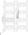
- Fig. 2 is a diagram showing an example of a layout of the traveling vehicle system according to the embodiment.
- the traveling vehicle system 1 includes a controller 100, a second communicator 200, and a traveling vehicle 300.
- the traveling vehicle system 1 is a system installed in a semiconductor device manufacturing factory.
- the traveling vehicle 300 transports containers such as FOUPs (Front-Opening Unified Pod) accommodating semiconductor wafers used for manufacturing semiconductor devices, or reticle pods accommodating processing members such as reticles.
- a plurality of controllers 100, a plurality of second communicators 200, and a plurality of traveling vehicles 300 may be provided in the traveling vehicle system 1.
- the track 10 is provided with a power supply line not shown in the drawings.
- the power supply line is arranged along the track 10.
- an alternating current is supplied to the power supply line.
- the traveling vehicle 300 includes a power receiving coil and receives power in a non-contact manner through electromagnetic induction from the power supply line. When power is supplied non-contactly, the generation of dust and other contaminants due to contact can be suppressed, making it suitable for use in a clean room.
- the track 10 is configured such that an island 20 is partitioned into one or more areas 30 (for example, areas 30a, 30b, 30c, 30d, and so on).
- second communicator 200 When no particular distinction is made between the second communicators 200a and 200b, they will simply be referred to as "second communicator 200". As shown in Fig. 2 , in those cases where the same communication channel is used in different areas 30, it is preferable that the areas 30 be separated by a predetermined distance or more in order to suppress interference.
- the state information includes information related to the current location, destination, driving state, and state of the transported article, along with traveling vehicle identification information identifying the traveling vehicle 300.
- the traveling state is information indicating the current speed of the traveling vehicle 300.
- the state of the transported article is information indicating the presence/absence and type of the article being transported.
- the memory storage 120 is, for example, a non-volatile memory, and stores state information received from the traveling vehicles 300 (each traveling vehicle 300) and map information related to the layout of the traveling vehicle system 1.
- the memory storage 120 also stores, in association with each other, area identification information for identifying each area 30 in the layout of the traveling vehicle system 1 and a communication channel corresponding to the communication method.
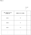
- Fig. 3 is a diagram showing an example of information stored in the controller according to the embodiment. As shown in Fig. 3 , the memory storage 120 stores, in association with each other, area identification information and communication channels. For example, the memory storage 120 stores, in association with each other, area identification information "area A" and a communication channel "30". The information shown in Fig. 3 may be included in the map information.
- the control unit 110 uses the information stored in the memory storage 120 to specify the area identification information of the area 30 in which a traveling vehicle 300 is located from the current location of the traveling vehicle 300, and specifies the communication channel corresponding to the communication method that can be used with the traveling vehicle 300. Then, the control unit 110 notifies the second communicator 200 of the specified communication channel via the wired communication processor 130.
- the second communicator 200 has a wired communication processor 210, a control unit 220, a memory storage 230, and a wireless communication processor 240, and facilitates the exchange of various information between the controller 100 and the traveling vehicle 300.
- the memory storage 230 stores, in association with each other, communication methods that can be used between the communicators (for example, between the first communicator 340 and the second communicator 200 described later) and communication channels corresponding to the communication methods.
- Fig. 4 is a diagram showing an example of information stored in the second communicator according to the embodiment. As shown in Fig. 4 , the memory storage 230 stores, in association with each other, communication channels "1 to 50" and a communication method A (for example, FSK: Frequency Shift Keying).
- communication channels for a communication method B are designated as "51 to 100," and communication channels for a communication method C (for example, high-speed OFDM) are designated as "101 to 120".
- the communication methods include the modulation methods.
- the memory storage 230 stores the communication method and communication channel that can be used by the second communicator 200 itself. Therefore, the memory storage 230 may not always store all of the communication methods and communication channels shown in Fig. 4 .
- These communication methods and communication channels are merely examples, and any communication method and communication channel can be set.
- the communication method may be optical wireless communication or wireless communication such as Wi-Fi.
- the control unit 220 comprehensively controls the second communicator 200 and executes various processes in the second communicator 200. For example, the control unit 220 receives a transport instruction and a communication channel from the controller 100 via the wired communication processor 210. The control unit 220 then specifies the communication method that corresponds to the communication channel, using the information stored in the memory storage 230. Thereafter, the control unit 220 transmits a transport instruction and so forth to the traveling vehicle 300 via the wireless communication processor 240, using the specified communication method. The wireless communication processor 240 performs modulation processing (such as wireless conversion) on data to be transmitted to the traveling vehicle 300 in accordance with the communication method.
- modulation processing such as wireless conversion
- the second communicator 200 may be replaced in some cases in order to improve the performance of the system. Accordingly, the replacement second communicator 200 may use a communication method different from the communication method that can be used by the previous second communicator 200.
- the modem capable of only using the communication method A shown in Fig. 4 may be replaced with a modem capable of using the communication methods B and C in addition to the communication method A.
- the controller 100 updates the information stored in the memory storage 120 regarding the area identification information and communication channel, and the information stored in the memory storage 230 regarding the communication channel and communication method. Then, the controller 100 transmits update information including the area identification information, the communication channel, and the communication method to the traveling vehicle 300 (each traveling vehicle 300).
- the traveling vehicle 300 has a control unit 310, a second memory storage 320, a wired communication processor 330, a first communicator 340, and a transmission/reception antenna 350.
- the first communicator 340 has a wired communication processor 341, a control unit 342, a memory storage 343, and a wireless communication processor 344, and facilitates the exchange of various information between the traveling vehicle 300 and the controller 100.
- the first memory storage 343 stores, in association with each other, communication methods and communication channels (see Fig. 4 ).
- the second memory storage 320 is, for example, a non-volatile memory, and stores various information received from the controller 100 and, as with the memory storage 120, map information related to the layout of the traveling vehicle system 1.
- the second memory storage 320 stores, in association with each other, area identification information and communication channels (see Fig. 3 ).
- the first communicator 340 communicates with the second communicator 200, using a communication method including a modulation method.
- the timing of replacing the first communicator 340 may be any timing, however, the present embodiment describes a case as an example, where (all of) the first communicators 340 are replaced before the second communicator 200 is replaced.
- the first communicators 340 may be replaced as needed without stopping all of the traveling vehicles 300 at the same time.
- Fig. 5 is a flowchart showing an example of the flow of processing performed by the controller upon replacement of the second communicator according to the embodiment.
- Step S101 YES
- the controller 100 updates the area identification information and the communication channel information stored in the memory storage 120 (Step S102).
- the controller 100 also updates the communication method information and the communication channel information stored in the memory storage 230 (Step S103).
- Step S101 NO
- the controller 100 is brought into a state of waiting for replacement of the second communicator 200 to occur. It should be noted that the processes of Step S102 and Step S103 may be executed in either order.
- Fig. 6 is a flowchart showing an example of the flow of processing performed in the traveling vehicle upon replacement of the second communicator according to the embodiment.
- Step S201 YES
- the traveling vehicle 300 updates the area identification information and the communication channel information stored in the second memory storage 320 (Step S202).
- the traveling vehicle 300 also updates the communication method information and the communication channel information stored in the first memory storage 343 (Step S203).
- Step S201: NO the traveling vehicle 300 is brought into a state of waiting to receive updated information. It should be noted that the processes of Step S202 and Step S203 may be executed in either order.
- the traveling vehicle 300 receives update information including the area identification information, communication channel, and communication method from the controller 100 via the first communicator 340, and updates the communication channel corresponding to the area identification information stored in the second memory storage 320.
- the traveling vehicle 300 instructs the first communicator 340 to also update the communication method information and the communication channel information stored in the first memory storage 343. This enables the traveling vehicle 300 to readily make a communication method selection for communicating with the replacement second communicator 200 without involving an additional new command for selecting (designating) the communication method.
- Fig. 7 is a flowchart showing an example of the flow of communication channel specification processing performed by the traveling vehicle according to the embodiment.
- the traveling vehicle 300 specifies the communication channel on the basis of the current location (Step S301). Then, the traveling vehicle 300 notifies the first communicator 340 of the specified communication channel (Step S302). Specifically, the traveling vehicle 300 specifies the communication channel that corresponds to the area identification information of the area 30 including its current location, using the information stored in the second memory storage 320. The traveling vehicle 300 then notifies the first communicator 340 of the specified communication channel in order to communicate with the controller 100 (the second communicator 200) using the communication method that corresponds to the specified communication channel.
- Fig. 8 is a flowchart showing an example of the flow of communication method specification processing performed by the first communicator according to the embodiment.
- the first communicator 340 acquires a communication channel from the traveling vehicle 300 (the control unit 310 of the traveling vehicle 300) (Step S401). Then, the first communicator 340 specifies the communication method that corresponds to the acquired communication channel, and communicates with the second communicator 200 using the specified communication method (Step S402). Specifically, when communicating with the second communicator 200, the first communicator 340 acquires a communication channel from the control unit 310.
- the first communicator 340 uses the information stored in the first memory storage 343 to specify the communication method that corresponds to the acquired communication channel, and, upon performing the modulation processing in accordance with the specified communication method, the first communicator 340 communicates with the second communicator 200.
- the information stored in the second memory storage 320 and the information stored in the first memory storage 343 are used to implement communication between the communicators, using the communication method that corresponds to the communication channel. It is thus possible to select a communication method without involving an additional new command for a communication method selection (designation).
- the traveling vehicle system 1 upon replacement of the second communicator 200, the traveling vehicle 300 receives update information including area identification information, a communication channel, and a communication method from the controller 100, and updates the communication channel information. It is thus possible to implement rapid information update in response to replacement of the second communicator 200 when applying a different communication method to a certain area 30.
- the first communicator 340 communicates with the second communicator 200, using the communication method including a modulation method. It is thus possible to implement communication between communicators, using communication methods corresponding to various modulation methods.
- the second memory storage 320 stores map information including the area identification information and the communication channel. It is thus possible to implement communication channel switching without changing the specifications of an existing system in which information such as communication channels are stored in the map information.
Landscapes
- Engineering & Computer Science (AREA)
- Computer Networks & Wireless Communication (AREA)
- Signal Processing (AREA)
- Aviation & Aerospace Engineering (AREA)
- Radar, Positioning & Navigation (AREA)
- Remote Sensing (AREA)
- Physics & Mathematics (AREA)
- General Physics & Mathematics (AREA)
- Automation & Control Theory (AREA)
- Mobile Radio Communication Systems (AREA)
Abstract
Description
- The present invention relates to a traveling vehicle system.
- Conventionally, a traveling vehicle system is known which includes a plurality of traveling vehicles traveling in partitioned areas and a controller that transmits traveling instructions and other instructions to each vehicle within each area.
Patent Literature 1 discloses a technique for storing channel information indicating, for each block, a wireless channel available for use, and for switching the wireless channel depending on the block corresponding to the current location in which the traveling vehicle is traveling. - [Patent Literature 1]
Japanese Patent No. 6895657 - In the conventional technique, channel information indicating an available wireless channel for each block is preliminarily prepared, and the wireless channel is switched depending on the current location of the traveling vehicle. Regarding such conventional technique, for example, it is assumed that an already installed communicator is replaced with another communicator that uses a different communication method. In such a case, during the replacement work of the communicator, the traveling vehicle selects a communication method that corresponds to the communicator to communicate with. However, a new command must be added to select the communication method that corresponds to the communicator. The conventional technique does not disclose a method for selecting (designating) the communication method.
- The present invention thus provides a traveling vehicle system and a traveling vehicle capable of selecting a communication method without involving an additional new command for selecting (designating) a communication method.
- A traveling vehicle system according to an aspect of the present invention comprises: a traveling vehicle including a first communicator; and a controller that communicates with the first communicator via a second communicator installed in each area in which the traveling vehicle travels and that controls traveling of the traveling vehicle, wherein the first communicator includes a first memory storage that stores, in association with each other, a communication method that can be used between communicators and a communication channel corresponding to the communication method, wherein the traveling vehicle includes a second memory storage that stores, in association with each other, area identification information for identifying each area and the communication channel, wherein the traveling vehicle specifies the communication channel to be used in an area including its current location, using information stored in the second memory storage, and wherein the first communicator specifies the communication method corresponding to the communication channel specified by the traveling vehicle, using information stored in the first memory storage, and communicates with the second communicator, using the communication channel and the communication method that have been specified.
- According to the traveling vehicle system of an aspect of the present invention, the traveling vehicle implements communication between communicators that use a communication method corresponding to a communication channel, using information stored in the memory storage. It is thus possible to select a communication method without involving an additional new command for a communication method selection (designation).
- In the traveling vehicle system of the above aspect, the traveling vehicle may acquire update information including the area identification information, the communication channel, and the communication method from the controller upon replacement of the second communicator, and update information stored in the first memory storage and the second memory storage. According to such an aspect, the information including a new communication channel is accepted from the controller and the communication channel information is updated. It is thus possible to implement rapid information update in response to replacement of the second communicator when applying a different communication method to a certain area. In the traveling vehicle system of the above aspect, the first communicator may communicate with the second communicator using the communication method including a modulation method. According to such an aspect, it is possible to implement communication between communicators using communication methods corresponding to various modulation methods. In the traveling vehicle system of the above aspect, the second memory storage may store map information pertaining to a layout of the traveling vehicle system, the map information including the area identification information and the communication channel, and the traveling vehicle may travel through each area on the basis of the map information. According to such an aspect, it is possible to implement communication channel switching without changing the specifications of an existing system in which information such as communication channels is stored in map information.
-
-
Fig. 1 is a diagram showing a configuration example of a traveling vehicle system according to an embodiment. -
Fig. 2 is a diagram showing an example of a layout of the traveling vehicle system according to the embodiment. -
Fig. 3 is a diagram showing an example of information stored in a controller according to the embodiment. -
Fig. 4 is a diagram showing an example of information stored in a second communicator according to the embodiment. -
Fig. 5 is a flowchart showing an example of the flow of processing performed by a controller upon replacement of the second communicator according to the embodiment. -
Fig. 6 is a flowchart showing an example of the flow of processing performed in a traveling vehicle upon replacement of the second communicator according to the embodiment. -
Fig. 7 is a flowchart showing an example of the flow of communication channel specification processing performed by the traveling vehicle according to the embodiment. -
Fig. 8 is a flowchart showing an example of the flow of communication method specification processing performed by a first communicator according to the embodiment. - Hereunder, an embodiment will be described, with reference to the drawings. However, the present invention should not be considered as limited to the embodiment described below. In the drawings, scale may be changed as necessary to illustrate the embodiment, such as by enlarging, reducing or emphasizing a portion.
-
Fig. 1 is a diagram showing a configuration example of a traveling vehicle system according to the embodiment.Fig. 2 is a diagram showing an example of a layout of the traveling vehicle system according to the embodiment. Thetraveling vehicle system 1 includes acontroller 100, asecond communicator 200, and atraveling vehicle 300. For example, thetraveling vehicle system 1 is a system installed in a semiconductor device manufacturing factory. On the basis of traveling instructions from thecontroller 100, the travelingvehicle 300 transports containers such as FOUPs (Front-Opening Unified Pod) accommodating semiconductor wafers used for manufacturing semiconductor devices, or reticle pods accommodating processing members such as reticles. A plurality ofcontrollers 100, a plurality ofsecond communicators 200, and a plurality oftraveling vehicles 300 may be provided in thetraveling vehicle system 1. - The
traveling vehicle 300 travels along atrack 10. Thetraveling vehicle 300 is, for example, an overhead traveling vehicle. Thetrack 10 is a traveling region, and is, for example, a traveling rail provided on a ceiling of a clean room or the like. The track R is provided adjacent to a processing apparatus not shown in the drawings, a stocker (automated warehouse) not shown in the drawings, or the like. The processing apparatus is, for example, an exposure apparatus, a coater/developer, a film forming apparatus, or an etching apparatus, and performs various processes on a semiconductor wafer in the container transported by thetraveling vehicle 300. The stocker stores, for example, containers transported by thetraveling vehicle 300. Thetraveling vehicle 300 may be a track-guided vehicle or a trackless vehicle. In those cases where thetraveling vehicle 300 is a track-guided vehicle that travels on the ground, thetrack 10 is provided on a floor or the like. - The
track 10 is provided with a power supply line not shown in the drawings. The power supply line is arranged along thetrack 10. For example, an alternating current is supplied to the power supply line. Thetraveling vehicle 300 includes a power receiving coil and receives power in a non-contact manner through electromagnetic induction from the power supply line. When power is supplied non-contactly, the generation of dust and other contaminants due to contact can be suppressed, making it suitable for use in a clean room. In the layout shown inFig. 2 , thetrack 10 is configured such that anisland 20 is partitioned into one or more areas 30 (for example,areas island 20 is a unit managed by onecontroller 100, and asecond communicator 200 is provided in eacharea 30. In other words, depending on the number of areas included in anisland 20, one or more second communicators 200 (for example,second communicators controller 100. Feeder cables 2 (2a, 2b) for wireless communication with thetraveling vehicle 300 are connected to the second communicators (200a, 200b). The layout shown in the figure is merely an example and can be configured in any desired layout. In the following description, when no particular distinction is made between theareas area 30". When no particular distinction is made between thesecond communicators second communicator 200". As shown inFig. 2 , in those cases where the same communication channel is used indifferent areas 30, it is preferable that theareas 30 be separated by a predetermined distance or more in order to suppress interference. - The
controller 100 communicates with thefirst communicator 340 via thesecond communicator 200 serving as a modem installed in each area 30 (for example,area 30a,area 30b,area 30c, orarea 30d) including thetrack 10 on which the travelingvehicle 300 travels, and transmits traveling instructions to the travelingvehicle 300. The travelingvehicle 300 includes thefirst communicator 340 serving as a modem, and travels through eacharea 30 on the basis of transport instructions received from thecontroller 100 via thefirst communicator 340 and thesecond communicator 200. The travelingvehicle 300 transmits its own state information to thecontroller 100 in response to a request from thecontroller 100. For example, the state information includes information related to the current location, destination, driving state, and state of the transported article, along with traveling vehicle identification information identifying the travelingvehicle 300. The traveling state is information indicating the current speed of the travelingvehicle 300. The state of the transported article is information indicating the presence/absence and type of the article being transported. - In the configuration mentioned above, the
controller 100 includes acontrol unit 110, amemory storage 120, and awired communication processor 130. Thecontrol unit 110 comprehensively controls thecontroller 100 and executes various processes in thecontroller 100. For example, thecontrol unit 110 generates a traveling instruction on the basis of the state information received from the travelingvehicle 300. Thecontrol unit 110 then transmits the generated traveling instruction to the travelingvehicle 300 via thesecond communicator 200. The communication between thecontroller 100 and the travelingvehicle 300 is implemented by a communication method corresponding to the current location of the travelingvehicle 300 to communicate with. - The
memory storage 120 is, for example, a non-volatile memory, and stores state information received from the traveling vehicles 300 (each traveling vehicle 300) and map information related to the layout of the travelingvehicle system 1. Thememory storage 120 also stores, in association with each other, area identification information for identifying eacharea 30 in the layout of the travelingvehicle system 1 and a communication channel corresponding to the communication method.Fig. 3 is a diagram showing an example of information stored in the controller according to the embodiment. As shown inFig. 3 , thememory storage 120 stores, in association with each other, area identification information and communication channels. For example, thememory storage 120 stores, in association with each other, area identification information "area A" and a communication channel "30". The information shown inFig. 3 may be included in the map information. Thecontrol unit 110 uses the information stored in thememory storage 120 to specify the area identification information of thearea 30 in which a travelingvehicle 300 is located from the current location of the travelingvehicle 300, and specifies the communication channel corresponding to the communication method that can be used with the travelingvehicle 300. Then, thecontrol unit 110 notifies thesecond communicator 200 of the specified communication channel via the wiredcommunication processor 130. - The
second communicator 200 has a wiredcommunication processor 210, acontrol unit 220, amemory storage 230, and awireless communication processor 240, and facilitates the exchange of various information between thecontroller 100 and the travelingvehicle 300. Thememory storage 230 stores, in association with each other, communication methods that can be used between the communicators (for example, between thefirst communicator 340 and thesecond communicator 200 described later) and communication channels corresponding to the communication methods.Fig. 4 is a diagram showing an example of information stored in the second communicator according to the embodiment. As shown inFig. 4 , thememory storage 230 stores, in association with each other, communication channels "1 to 50" and a communication method A (for example, FSK: Frequency Shift Keying). In addition, inFig. 4 , communication channels for a communication method B (for example, low-speed OFDM: Orthogonal Frequency Division Multiplexing) are designated as "51 to 100," and communication channels for a communication method C (for example, high-speed OFDM) are designated as "101 to 120". Thus, the communication methods include the modulation methods. Thememory storage 230 stores the communication method and communication channel that can be used by thesecond communicator 200 itself. Therefore, thememory storage 230 may not always store all of the communication methods and communication channels shown inFig. 4 . These communication methods and communication channels are merely examples, and any communication method and communication channel can be set. For example, the communication method may be optical wireless communication or wireless communication such as Wi-Fi. - The
control unit 220 comprehensively controls thesecond communicator 200 and executes various processes in thesecond communicator 200. For example, thecontrol unit 220 receives a transport instruction and a communication channel from thecontroller 100 via the wiredcommunication processor 210. Thecontrol unit 220 then specifies the communication method that corresponds to the communication channel, using the information stored in thememory storage 230. Thereafter, thecontrol unit 220 transmits a transport instruction and so forth to the travelingvehicle 300 via thewireless communication processor 240, using the specified communication method. Thewireless communication processor 240 performs modulation processing (such as wireless conversion) on data to be transmitted to the travelingvehicle 300 in accordance with the communication method. - Here, in the traveling
vehicle system 1, thesecond communicator 200 may be replaced in some cases in order to improve the performance of the system. Accordingly, the replacementsecond communicator 200 may use a communication method different from the communication method that can be used by the previoussecond communicator 200. For example, in the travelingvehicle system 1, the modem capable of only using the communication method A shown inFig. 4 may be replaced with a modem capable of using the communication methods B and C in addition to the communication method A. Upon replacing thesecond communicator 200, thecontroller 100 updates the information stored in thememory storage 120 regarding the area identification information and communication channel, and the information stored in thememory storage 230 regarding the communication channel and communication method. Then, thecontroller 100 transmits update information including the area identification information, the communication channel, and the communication method to the traveling vehicle 300 (each traveling vehicle 300). - The traveling
vehicle 300 has acontrol unit 310, asecond memory storage 320, awired communication processor 330, afirst communicator 340, and a transmission/reception antenna 350. Thefirst communicator 340 has a wiredcommunication processor 341, acontrol unit 342, amemory storage 343, and awireless communication processor 344, and facilitates the exchange of various information between the travelingvehicle 300 and thecontroller 100. As with thememory storage 230, thefirst memory storage 343 stores, in association with each other, communication methods and communication channels (seeFig. 4 ). Thesecond memory storage 320 is, for example, a non-volatile memory, and stores various information received from thecontroller 100 and, as with thememory storage 120, map information related to the layout of the travelingvehicle system 1. As with thememory storage 120, thesecond memory storage 320 stores, in association with each other, area identification information and communication channels (seeFig. 3 ). As with thesecond communicator 200, thefirst communicator 340 communicates with thesecond communicator 200, using a communication method including a modulation method. - The
control unit 310 comprehensively controls the travelingvehicle 300 and executes various processes in the travelingvehicle 300. For example, thecontrol unit 310 causes the travelingvehicle 300 to travel through eacharea 30 on the basis of the map information stored in thesecond memory storage 320. Thecontroller 300 acquires update information including area identification information, a communication channel, and a communication method from thecontroller 100 upon replacement of thesecond communicator 200, and updates the information stored in thefirst memory storage 343 and thesecond memory storage 320. As described above, in the travelingvehicle system 1, thesecond communicator 200 may be replaced in some cases. As with thesecond communicator 200, in the travelingvehicle system 1, thefirst communicator 340 is replaced. The timing of replacing thefirst communicator 340 may be any timing, however, the present embodiment describes a case as an example, where (all of) thefirst communicators 340 are replaced before thesecond communicator 200 is replaced. Thefirst communicators 340 may be replaced as needed without stopping all of the travelingvehicles 300 at the same time. - In order to communicate with the
controller 100, thecontrol unit 310 uses the information stored in thesecond memory storage 320 to specify the communication channel to be used in the area including its current location, and notifies thefirst communicator 340 via the wiredcommunication processor 330. Thecontrol unit 342 comprehensively controls thefirst communicator 340 and executes various processes in thefirst communicator 340. For example, thecontrol unit 342 uses the information stored in thefirst memory storage 343 to specify the communication method that corresponds to the communication channel specified by thecontrol unit 310 of the travelingvehicle 300, and communicates with thesecond communicator 200 via the communication channel and communication method specified. Thecontrol unit 342 acquires the communication channel specified by thecontrol unit 310 via the wiredcommunication processor 341. Thewireless communication processor 344 performs modulation processing (such as wireless conversion) on data to be transmitted to thecontroller 100 in accordance with the communication method. The transmission/reception antenna 350 is connected to thefeeder cable 2 and transmits modulated data to thecontroller 100. -
Fig. 5 is a flowchart showing an example of the flow of processing performed by the controller upon replacement of the second communicator according to the embodiment. As shown inFig. 5 , if thesecond communicator 200 has been replaced (Step S101: YES), thecontroller 100 updates the area identification information and the communication channel information stored in the memory storage 120 (Step S102). Thecontroller 100 also updates the communication method information and the communication channel information stored in the memory storage 230 (Step S103). On the other hand, if thesecond communicator 200 has not been replaced (Step S101: NO), thecontroller 100 is brought into a state of waiting for replacement of thesecond communicator 200 to occur. It should be noted that the processes of Step S102 and Step S103 may be executed in either order. - Specifically, the
controller 100, upon replacement of thesecond communicator 200, stops the system of the target area 30 (thearea 30 that includes thesecond communicator 200 to be replaced), and then updates the information on the communication channel (stored in the memory storage 120) corresponding to the communication method that will be available for use in thearea 30 where the system has been stopped. In addition, thecontroller 100 instructs thesecond communicator 200 to also update the communication method information and the communication channel information stored in thememory storage 230. - Then, the
controller 100 transmits update information to the travelingvehicle 300 and restarts the system in the target area 30 (Step S104). Specifically, thecontroller 100 transmits the update information including the area identification information, communication channel information, and communication method information to the travelingvehicle 300 via thesecond communicator 200. Thecontroller 100 then resumes the system for thetarget area 30 where the system has been stopped. As described above, replacement of thesecond communicator 200 is performed on an area-30-by-area-30 (island-20-by-island-20) basis without stopping the entire travelingvehicle system 1. -
Fig. 6 is a flowchart showing an example of the flow of processing performed in the traveling vehicle upon replacement of the second communicator according to the embodiment. As shown inFig. 6 , if update information has been received (Step S201: YES), the travelingvehicle 300 updates the area identification information and the communication channel information stored in the second memory storage 320 (Step S202). The travelingvehicle 300 also updates the communication method information and the communication channel information stored in the first memory storage 343 (Step S203). On the other hand, if updated information has not been received (Step S201: NO), the travelingvehicle 300 is brought into a state of waiting to receive updated information. It should be noted that the processes of Step S202 and Step S203 may be executed in either order. - Specifically, the traveling
vehicle 300 receives update information including the area identification information, communication channel, and communication method from thecontroller 100 via thefirst communicator 340, and updates the communication channel corresponding to the area identification information stored in thesecond memory storage 320. In addition, the travelingvehicle 300 instructs thefirst communicator 340 to also update the communication method information and the communication channel information stored in thefirst memory storage 343. This enables the travelingvehicle 300 to readily make a communication method selection for communicating with the replacementsecond communicator 200 without involving an additional new command for selecting (designating) the communication method. -
Fig. 7 is a flowchart showing an example of the flow of communication channel specification processing performed by the traveling vehicle according to the embodiment. As shown inFig. 7 , the travelingvehicle 300 specifies the communication channel on the basis of the current location (Step S301). Then, the travelingvehicle 300 notifies thefirst communicator 340 of the specified communication channel (Step S302). Specifically, the travelingvehicle 300 specifies the communication channel that corresponds to the area identification information of thearea 30 including its current location, using the information stored in thesecond memory storage 320. The travelingvehicle 300 then notifies thefirst communicator 340 of the specified communication channel in order to communicate with the controller 100 (the second communicator 200) using the communication method that corresponds to the specified communication channel. -
Fig. 8 is a flowchart showing an example of the flow of communication method specification processing performed by the first communicator according to the embodiment. As shown inFig. 8 , thefirst communicator 340 acquires a communication channel from the traveling vehicle 300 (thecontrol unit 310 of the traveling vehicle 300) (Step S401). Then, thefirst communicator 340 specifies the communication method that corresponds to the acquired communication channel, and communicates with thesecond communicator 200 using the specified communication method (Step S402). Specifically, when communicating with thesecond communicator 200, thefirst communicator 340 acquires a communication channel from thecontrol unit 310. Then, thefirst communicator 340 uses the information stored in thefirst memory storage 343 to specify the communication method that corresponds to the acquired communication channel, and, upon performing the modulation processing in accordance with the specified communication method, thefirst communicator 340 communicates with thesecond communicator 200. - As have been described above, according to the traveling
vehicle system 1 of the embodiment, the information stored in thesecond memory storage 320 and the information stored in thefirst memory storage 343 are used to implement communication between the communicators, using the communication method that corresponds to the communication channel. It is thus possible to select a communication method without involving an additional new command for a communication method selection (designation). According to the travelingvehicle system 1, upon replacement of thesecond communicator 200, the travelingvehicle 300 receives update information including area identification information, a communication channel, and a communication method from thecontroller 100, and updates the communication channel information. It is thus possible to implement rapid information update in response to replacement of thesecond communicator 200 when applying a different communication method to acertain area 30. According to the travelingvehicle system 1, thefirst communicator 340 communicates with thesecond communicator 200, using the communication method including a modulation method. It is thus possible to implement communication between communicators, using communication methods corresponding to various modulation methods. According to the travelingvehicle system 1, thesecond memory storage 320 stores map information including the area identification information and the communication channel. It is thus possible to implement communication channel switching without changing the specifications of an existing system in which information such as communication channels are stored in the map information. - The embodiment of the present invention has been described above. However, the technical scope of the invention is not limited to the description of the above embodiment. It is apparent to those skilled in the art that various modifications or improvements can be added to the above embodiment. The technical scope of the present invention also encompasses one or more of such modifications or improvements. One or more of the requirements described in the above embodiment may be omitted in some cases. Furthermore, one or more of the requirements described in the above embodiment may be combined where appropriate. The contents of all documents cited in the detailed description of the present invention are incorporated herein by reference to the extent permitted by law.
- It should be noted that the technical scope of the present invention is not limited to the mode described in the above embodiment. One or more of the requirements described in the above embodiment may be omitted in some cases. One or more of the requirements described in the above embodiment may be combined where appropriate. The contents of
Japanese Patent Application No. 2022-092437 -
- 1:
- Traveling vehicle system
- 100:
- Controller
- 200:
- Second communicator
- 300:
- Traveling vehicle
- 310:
- Control unit
- 320:
- Second memory storage
- 330:
- Wired communication processor
- 340:
- First communicator
- 341:
- Wired communication processor
- 342:
- Control unit
- 343:
- First memory storage
- 344:
- Wireless communication processor
- 350:
- Transmission/reception antenna
Claims (5)
- A traveling vehicle system comprising:a traveling vehicle including a first communicator; anda controller that communicates with the first communicator via a second communicator installed in each area in which the traveling vehicle travels and that controls traveling of the traveling vehicle,wherein the first communicator includes a first memory storage that stores, in association with each other, a communication method that can be used between communicators and a communication channel corresponding to the communication method,wherein the traveling vehicle includes a second memory storage that stores, in association with each other, area identification information for identifying each area and the communication channel,wherein the traveling vehicle specifies the communication channel to be used in an area including its current location, using the information stored in the second memory storage, andwherein the first communicator specifies the communication method corresponding to the communication channel specified by the traveling vehicle, using information stored in the first memory storage, and communicates with the second communicator, using the communication channel and the communication method that have been specified.
- The traveling vehicle system according to claim 1,
wherein the traveling vehicle acquires update information including the area identification information, the communication channel, and the communication method from the controller upon replacement of the second communicator, and updates information stored in the first memory storage and the second memory storage. - The traveling vehicle system according to claim 1 or 2,
wherein the first communicator communicates with the second communicator using the communication method including a modulation method. - The traveling vehicle system according to claim 1 or 2,wherein the second memory storage stores map information pertaining to a layout of the traveling vehicle system, the map information including the area identification information and the communication channel, andwherein the traveling vehicle travels through each area on the basis of the map information.
- The traveling vehicle system according to claim 3,wherein the second memory storage stores map information pertaining to a layout of the traveling vehicle system, the map information including the area identification information and the communication channel, andwherein the traveling vehicle travels through each area on the basis of the map information.
Applications Claiming Priority (2)
| Application Number | Priority Date | Filing Date | Title |
|---|---|---|---|
| JP2022092437 | 2022-06-07 | ||
| PCT/JP2023/016105 WO2023238529A1 (en) | 2022-06-07 | 2023-04-24 | Traveling vehicle system |
Publications (2)
| Publication Number | Publication Date |
|---|---|
| EP4539546A1 true EP4539546A1 (en) | 2025-04-16 |
| EP4539546A4 EP4539546A4 (en) | 2026-01-21 |
Family
ID=89118029
Family Applications (1)
| Application Number | Title | Priority Date | Filing Date |
|---|---|---|---|
| EP23819516.8A Pending EP4539546A4 (en) | 2022-06-07 | 2023-04-24 | TRAVEL VEHICLE SYSTEM |
Country Status (5)
| Country | Link |
|---|---|
| EP (1) | EP4539546A4 (en) |
| JP (1) | JP7722581B2 (en) |
| CN (1) | CN119138017A (en) |
| TW (1) | TW202349976A (en) |
| WO (1) | WO2023238529A1 (en) |
Family Cites Families (5)
| Publication number | Priority date | Publication date | Assignee | Title |
|---|---|---|---|---|
| JP2002199459A (en) * | 2000-12-27 | 2002-07-12 | Matsushita Electric Ind Co Ltd | Communication terminal device, base station device and communication method |
| JP2006262176A (en) * | 2005-03-17 | 2006-09-28 | Tdk Corp | Onboard radio lan device |
| JP6895657B2 (en) * | 2017-01-31 | 2021-06-30 | サイレックス・テクノロジー株式会社 | Unmanned vehicle, driving system, and control method of unmanned vehicle |
| JP7130393B2 (en) * | 2018-03-12 | 2022-09-05 | 矢崎総業株式会社 | vehicle communication system |
| JP6840316B1 (en) | 2020-12-10 | 2021-03-10 | 株式会社アイエムイー | Weighing equipment and packaging production line |
-
2023
- 2023-04-24 JP JP2024526280A patent/JP7722581B2/en active Active
- 2023-04-24 WO PCT/JP2023/016105 patent/WO2023238529A1/en not_active Ceased
- 2023-04-24 EP EP23819516.8A patent/EP4539546A4/en active Pending
- 2023-04-24 CN CN202380037915.7A patent/CN119138017A/en active Pending
- 2023-05-03 TW TW112116412A patent/TW202349976A/en unknown
Also Published As
| Publication number | Publication date |
|---|---|
| CN119138017A (en) | 2024-12-13 |
| TW202349976A (en) | 2023-12-16 |
| JPWO2023238529A1 (en) | 2023-12-14 |
| EP4539546A4 (en) | 2026-01-21 |
| JP7722581B2 (en) | 2025-08-13 |
| WO2023238529A1 (en) | 2023-12-14 |
Similar Documents
| Publication | Publication Date | Title |
|---|---|---|
| US9086697B2 (en) | Processing facility | |
| KR102374029B1 (en) | Control method of conveyance system, conveyance system and management apparatus | |
| US11339008B2 (en) | Transport system, transport controller, and transport vehicle control method | |
| US20230395415A1 (en) | Wafer Transportation | |
| EP3971111A1 (en) | Transport system and transport control method | |
| JP4441931B2 (en) | Conveyor cart system | |
| JP2022112098A (en) | Article conveying facility | |
| JP2006313462A (en) | Conveyor cart system | |
| JP2023066763A (en) | Radio communication system, carriage side communication device and communication method | |
| US12452706B2 (en) | Article transport facility | |
| JP7722581B2 (en) | Vehicle System | |
| US20230322486A1 (en) | Transport vehicle system and method of controlling transport vehicle | |
| JP2006313461A (en) | Conveyor cart system | |
| US20230406644A1 (en) | Article Transport Facility | |
| EP4184274B1 (en) | Traveling vehicle system | |
| JP5353222B2 (en) | Traveling vehicle system | |
| JP2002175116A (en) | Automatic guided vehicle system | |
| JP2024023053A (en) | Conveyance system, conveyance system control method, control program, and recording medium | |
| JP2002189520A (en) | Transport system and transport vehicle control method | |
| CN120987030A (en) | Wafer transfer methods, devices, virtual tracks, electronic devices and storage media | |
| JP2006313767A (en) | Conveyor cart system | |
| JP2010067028A (en) | Transfer control device and transfer system | |
| US10593578B2 (en) | Initialization setting method for RF communication of unmanned transporting device in automated material handling system | |
| KR20240130616A (en) | Control system | |
| JP2001156145A (en) | Transfer instruction allocation method for automatic transfer system |
Legal Events
| Date | Code | Title | Description |
|---|---|---|---|
| STAA | Information on the status of an ep patent application or granted ep patent |
Free format text: STATUS: THE INTERNATIONAL PUBLICATION HAS BEEN MADE |
|
| PUAI | Public reference made under article 153(3) epc to a published international application that has entered the european phase |
Free format text: ORIGINAL CODE: 0009012 |
|
| STAA | Information on the status of an ep patent application or granted ep patent |
Free format text: STATUS: REQUEST FOR EXAMINATION WAS MADE |
|
| 17P | Request for examination filed |
Effective date: 20241112 |
|
| AK | Designated contracting states |
Kind code of ref document: A1 Designated state(s): AL AT BE BG CH CY CZ DE DK EE ES FI FR GB GR HR HU IE IS IT LI LT LU LV MC ME MK MT NL NO PL PT RO RS SE SI SK SM TR |
|
| DAV | Request for validation of the european patent (deleted) | ||
| DAX | Request for extension of the european patent (deleted) | ||
| REG | Reference to a national code |
Ref country code: DE Ref legal event code: R079 Free format text: PREVIOUS MAIN CLASS: H04W0036320000 Ipc: H04W0004440000 |
|
| A4 | Supplementary search report drawn up and despatched |
Effective date: 20251222 |
|
| RIC1 | Information provided on ipc code assigned before grant |
Ipc: H04W 4/44 20180101AFI20251216BHEP Ipc: H04W 4/021 20180101ALI20251216BHEP Ipc: H04W 36/32 20090101ALI20251216BHEP Ipc: G05D 1/226 20240101ALI20251216BHEP Ipc: G05D 105/28 20240101ALI20251216BHEP Ipc: G05D 107/70 20240101ALI20251216BHEP Ipc: G05D 109/10 20240101ALI20251216BHEP |