EP4539506A1 - Electronic apparatus - Google Patents
Electronic apparatus Download PDFInfo
- Publication number
- EP4539506A1 EP4539506A1 EP23838492.9A EP23838492A EP4539506A1 EP 4539506 A1 EP4539506 A1 EP 4539506A1 EP 23838492 A EP23838492 A EP 23838492A EP 4539506 A1 EP4539506 A1 EP 4539506A1
- Authority
- EP
- European Patent Office
- Prior art keywords
- hole
- cavity
- housing
- electronic device
- sound
- Prior art date
- Legal status (The legal status is an assumption and is not a legal conclusion. Google has not performed a legal analysis and makes no representation as to the accuracy of the status listed.)
- Pending
Links
Images








Classifications
-
- G—PHYSICS
- G06—COMPUTING OR CALCULATING; COUNTING
- G06F—ELECTRIC DIGITAL DATA PROCESSING
- G06F1/00—Details not covered by groups G06F3/00 - G06F13/00 and G06F21/00
- G06F1/16—Constructional details or arrangements
- G06F1/1613—Constructional details or arrangements for portable computers
- G06F1/1633—Constructional details or arrangements of portable computers not specific to the type of enclosures covered by groups G06F1/1615 - G06F1/1626
- G06F1/1684—Constructional details or arrangements related to integrated I/O peripherals not covered by groups G06F1/1635 - G06F1/1675
- G06F1/1688—Constructional details or arrangements related to integrated I/O peripherals not covered by groups G06F1/1635 - G06F1/1675 the I/O peripheral being integrated loudspeakers
-
- G—PHYSICS
- G06—COMPUTING OR CALCULATING; COUNTING
- G06F—ELECTRIC DIGITAL DATA PROCESSING
- G06F1/00—Details not covered by groups G06F3/00 - G06F13/00 and G06F21/00
- G06F1/16—Constructional details or arrangements
-
- H—ELECTRICITY
- H04—ELECTRIC COMMUNICATION TECHNIQUE
- H04M—TELEPHONIC COMMUNICATION
- H04M1/00—Substation equipment, e.g. for use by subscribers
- H04M1/02—Constructional features of telephone sets
-
- H—ELECTRICITY
- H04—ELECTRIC COMMUNICATION TECHNIQUE
- H04M—TELEPHONIC COMMUNICATION
- H04M1/00—Substation equipment, e.g. for use by subscribers
- H04M1/02—Constructional features of telephone sets
- H04M1/0202—Portable telephone sets, e.g. cordless phones, mobile phones or bar type handsets
- H04M1/026—Details of the structure or mounting of specific components
-
- H—ELECTRICITY
- H04—ELECTRIC COMMUNICATION TECHNIQUE
- H04M—TELEPHONIC COMMUNICATION
- H04M1/00—Substation equipment, e.g. for use by subscribers
- H04M1/02—Constructional features of telephone sets
- H04M1/03—Constructional features of telephone transmitters or receivers, e.g. telephone hand-sets
-
- H—ELECTRICITY
- H04—ELECTRIC COMMUNICATION TECHNIQUE
- H04M—TELEPHONIC COMMUNICATION
- H04M1/00—Substation equipment, e.g. for use by subscribers
- H04M1/02—Constructional features of telephone sets
- H04M1/03—Constructional features of telephone transmitters or receivers, e.g. telephone hand-sets
- H04M1/035—Improving the acoustic characteristics by means of constructional features of the housing, e.g. ribs, walls, resonating chambers or cavities
-
- H—ELECTRICITY
- H04—ELECTRIC COMMUNICATION TECHNIQUE
- H04M—TELEPHONIC COMMUNICATION
- H04M1/00—Substation equipment, e.g. for use by subscribers
- H04M1/02—Constructional features of telephone sets
- H04M1/18—Telephone sets specially adapted for use in ships, mines, or other places exposed to adverse environment
-
- H—ELECTRICITY
- H04—ELECTRIC COMMUNICATION TECHNIQUE
- H04R—LOUDSPEAKERS, MICROPHONES, GRAMOPHONE PICK-UPS OR LIKE ACOUSTIC ELECTROMECHANICAL TRANSDUCERS; ELECTRIC HEARING AIDS; PUBLIC ADDRESS SYSTEMS
- H04R1/00—Details of transducers, loudspeakers or microphones
- H04R1/20—Arrangements for obtaining desired frequency or directional characteristics
- H04R1/32—Arrangements for obtaining desired frequency or directional characteristics for obtaining desired directional characteristic only
- H04R1/34—Arrangements for obtaining desired frequency or directional characteristics for obtaining desired directional characteristic only by using a single transducer with sound reflecting, diffracting, directing or guiding means
- H04R1/345—Arrangements for obtaining desired frequency or directional characteristics for obtaining desired directional characteristic only by using a single transducer with sound reflecting, diffracting, directing or guiding means for loudspeakers
-
- H—ELECTRICITY
- H04—ELECTRIC COMMUNICATION TECHNIQUE
- H04R—LOUDSPEAKERS, MICROPHONES, GRAMOPHONE PICK-UPS OR LIKE ACOUSTIC ELECTROMECHANICAL TRANSDUCERS; ELECTRIC HEARING AIDS; PUBLIC ADDRESS SYSTEMS
- H04R9/00—Transducers of moving-coil, moving-strip, or moving-wire type
- H04R9/06—Loudspeakers
-
- H—ELECTRICITY
- H04—ELECTRIC COMMUNICATION TECHNIQUE
- H04R—LOUDSPEAKERS, MICROPHONES, GRAMOPHONE PICK-UPS OR LIKE ACOUSTIC ELECTROMECHANICAL TRANSDUCERS; ELECTRIC HEARING AIDS; PUBLIC ADDRESS SYSTEMS
- H04R1/00—Details of transducers, loudspeakers or microphones
- H04R1/02—Casings; Cabinets ; Supports therefor; Mountings therein
- H04R1/023—Screens for loudspeakers
-
- H—ELECTRICITY
- H04—ELECTRIC COMMUNICATION TECHNIQUE
- H04R—LOUDSPEAKERS, MICROPHONES, GRAMOPHONE PICK-UPS OR LIKE ACOUSTIC ELECTROMECHANICAL TRANSDUCERS; ELECTRIC HEARING AIDS; PUBLIC ADDRESS SYSTEMS
- H04R2499/00—Aspects covered by H04R or H04S not otherwise provided for in their subgroups
- H04R2499/10—General applications
- H04R2499/11—Transducers incorporated or for use in hand-held devices, e.g. mobile phones, PDA's, camera's
Definitions
- Embodiments of this application provide an electronic device.
- a speaker module in the electronic device occupies a small space in a longitudinal direction and can be adapted to assembly of an electronic device with a limited longitudinal space.
- an embodiment of this application provides an electronic device, and the electronic device may specifically be a mobile phone, a tablet computer, and the like.
- the electronic device includes a first housing, a second housing, a speaker module, and a speaker bracket.
- the first housing and the second housing are connected to each other along a thickness direction of the electronic device, and can form an external structure of the electronic device.
- the second housing is further provided with a first sound outlet hole and a second sound outlet hole.
- the speaker module includes a first sound emitting portion and a second sound emitting portion, the first sound emitting portion faces the first housing, and the second sound emitting portion faces the second housing.
- the speaker bracket is provided with a communication cavity, and at least part of the communication cavity extends along a transverse direction of the electronic device.
- the speaker bracket has a first connecting end and a second connecting end spaced apart in the transverse direction of the electronic device.
- the first connecting end is sealing assembled to the first sound emitting portion, so that the first sound emitting portion is capable of emitting a sound wave into the communication cavity
- the second connecting end is sealing assembled to the second housing, so that the communication cavity is in communication with the first sound outlet hole.
- the second sound emitting portion is assembled to the second housing, so that the second sound emitting portion is capable of emitting a sound wave into the second sound outlet hole.
- the solution provided in embodiments of this application may be applied to the electronic device with a relatively limited longitudinal space, or may be applied to the electronic device with a relatively sufficient longitudinal space, and types of electronic devices to which the solution is adapted may further increase.
- this embodiment of this application further provides a first implementation of the first aspect: the second housing may further be provided with a first sound outlet cavity, and the first sound outlet cavity is configured to communicate the first sound outlet hole and the communication cavity.
- the first sound outlet cavity can form a buffer space between the communication cavity and the first sound outlet hole to guide the sound wave in the communication cavity to the first sound outlet hole for playback, which is beneficial to reducing eddy currents during sound wave transmission and reducing noise, thereby ensuring a better sound playback quality.
- the first sound outlet cavity may not be provided.
- the communication cavity may be directly in communication with the first sound outlet hole.
- this embodiment of this application further provides a sixth implementation of the first aspect: the first hole portion includes a first hole section and a second hole section that are in communication with each other, the first hole section is in communication with the communication cavity, an end of the second hole section away from the first housing is blocked by the blocking component, and the first hole section and the second hole section are not coaxial.
- an opening area of the first hole portion on a surface of the middle plate that faces the first housing and an opening area of a surface that faces the screen may be smaller, which can reduce an inner space of the first hole portion, thereby further reducing the impact on the strength of the middle plate.
- the opening area of the first hole portion on the surface of the middle plate that faces the first housing (that is, the opening area of the first hole section) may be smaller, correspondingly, a size of the second connecting end connected to the first hole section in the transverse direction of the electronic device may also be smaller, and a size of the speaker bracket in the transverse direction of the electronic device may also be reduced, thereby reducing the mounting space occupied by the speaker module in the transverse direction of the electronic device to a certain extent.
- this embodiment of this application further provides an eighth implementation of the first aspect: the frame is provided with a first sealing end surface surrounding the first sound outlet cavity, the first sealing end surface is arranged at an angle with the thickness direction, the second connecting end has a second sealing end surface, and the first sealing end surface is sealingly assembled with the second sealing end surface.
- the assembly of the first sealing end surface and the second sealing end surface is a bevel connection. An assembly process is relatively simple, and it is not easy to cause damage to a sealing portion between the two sealing end surfaces.
- the second housing further includes a screen
- the screen is mounted on a side of the middle plate that faces away from the first housing
- the blocking component is the screen.
- the screen is a component of the electronic device.
- the second hole portion includes a third hole section and a fourth hole section that are in communication with each other, the third hole section is in communication with the first sound outlet hole, the fourth hole section is in communication with the third hole portion, and a size of the third hole section along the thickness direction is larger than that of the fourth hole section.
- the fourth hole section may be set shallower, which can reduce the digging volume of the middle plate, thereby reducing the impact on the strength of the middle plate, so that the middle frame can have a relatively high structural strength.
- this embodiment of this application further provides a thirteenth implementation of the first aspect: orthographic projections of the second hole portion and the third hole portion on the middle plate do not extend on a same straight line.
- orthographic projections of the second hole portion and the third hole portion on the middle plate do not extend on a same straight line.
- the communication cavity includes a first sub-cavity, a second sub-cavity, and a third sub-cavity that are in communication in sequence;
- the first sub-cavity is connected to the first sound emitting portion and is configured to directly receive a vibrating sound of the first sound emitting portion; at least part of the second sub-cavity extends along the transverse direction of the electronic device to achieve a transverse extension design of the communication cavity; and the third sub-cavity may be in communication with the first sound outlet hole, so that the sound produced by the first sound emitting portion can be played through the first sound outlet hole.
- this embodiment of this application further provides a fifteenth implementation of the first aspect: an area of a cross-section of the third sub-cavity perpendicular to an axial direction of the third sub-cavity is smaller than an area of a cross-section of the first sub-cavity perpendicular to an axial direction of the first sub-cavity.
- the speaker bracket includes a bottom plate portion and a frame portion that are separate, the frame portion is provided with a first through hole and a second through hole, the bottom plate portion is mounted on an axial end of the frame portion, the bottom plate portion and the frame portion enclose the first sub-cavity, the second sub-cavity, and the third sub-cavity, the first sub-cavity includes an inner space of the first through hole, and the third sub-cavity includes an inner space of the second through hole.
- the split design of the speaker bracket can facilitate formation of a communication cavity with a complex extending direction.
- this embodiment of this application further provides a twentieth implementation of the first aspect: the first connecting end has a first sealing surface, a direction in which the first sound emitting portion and the second sound emitting portion are arranged opposite to each other is an axial direction of the speaker module, the first sealing surface is perpendicular to the axial direction of the speaker module, and the first sound emitting portion is sealingly mounted on the first sealing surface.
- a sealing form between the first sound emitting portion and the first sealing surface may be dispensing, gum, or a combination of dispensing and gum.
- the first sealing surface and the second sealing surface may be used selectively, or both may be arranged.
- the electronic device may further include a main board bracket; and the main board bracket may be press-connected to the speaker bracket toward the second housing to prevent the speaker bracket from lifting after mounting, which can improve the mounting reliability of the speaker bracket, thereby improving the mounting reliability of the speaker module; or the speaker bracket may also be mounted on the main board bracket; or the speaker bracket and the main board bracket may be of an integrated structure. In this way, a quantity of components may be reduced and the mounting process of the electronic device may be simplified.
- this embodiment of this application further provides a twenty-fourth implementation of the first aspect: the second housing is provided with a second sound outlet cavity, the second sound outlet cavity is in communication with the second sound outlet hole, and the second sound outlet cavity is connected to the second sound emitting portion, so that the second sound emitting portion can emit a sound wave to the second sound outlet cavity.
- the second sound outlet cavity can form a buffer space between the communication cavity and the second sound outlet hole to guide the sound wave in the communication cavity to the second sound outlet hole for playback, which is beneficial to reducing eddy currents during sound wave transmission and reducing noise, thereby ensuring a better sound playback quality.
- this embodiment of this application further provides a twenty-fifth implementation of the first aspect: the second housing includes a middle frame and a screen, the middle frame includes a frame and a middle plate, the screen is mounted on a side of the middle plate that faces away from the first housing, the middle plate is provided with a fourth hole portion, and the second sound outlet cavity includes an inner space of the fourth hole portion; and the second sound outlet hole is provided on the frame, and/or the second sound outlet hole is provided between the frame and the screen.
- this embodiment of this application further provides a twenty-sixth implementation of the first aspect: a transition space is further provided between the screen and the middle frame, the transition space connects the second sound outlet hole to the fourth hole portion, the second sound outlet cavity includes the transition space, and the transition space is gradually expanded along a direction close to the second sound outlet hole, so that a size transition between a sound region of the second sound outlet hole and the fourth hole portion may be formed, which can better avoid sudden changes in size, thereby improving the sound playback quality.
- this embodiment of this application further provides a twenty-seventh implementation of the first aspect: at least one of a connecting position between the speaker module and the first connecting end, a connecting position between the speaker module and the second housing, and a connecting position between the second connecting end and the second housing is provided with a dustproof net, so that anti-dust performance of the speaker module is improved.
- the main board may control the first sound emitting portion and the second sound emitting portion to emit the sound waves in opposite phases respectively to offset sound leakage, thereby improving the privacy of calls.
- the first sound emitting portion and the second sound emitting portion may also emit the sound waves in the same phase to enhance a stereo effect.
- the speaker bracket is provided with a communication cavity, and the speaker bracket has a first connecting end and a second connecting end.
- the first connecting end is sealingly assembled to the first sound emitting portion, so that the first sound emitting portion can emit a sound wave into the communication cavity.
- the second connecting end is sealingly assembled to the second housing along a first direction, so that the communication cavity is in communication with the first sound outlet hole.
- the second sound emitting portion is sealingly assembled to the second housing along a second direction, so that the second sound emitting portion can emit a sound wave into the second sound outlet hole. Sealing portions are provided between the second sound emitting portion and the second housing, and between the second connecting end and the second housing.
- the foregoing first direction is a longitudinal direction or a transverse direction of the electronic device
- the foregoing second direction is a thickness direction of the electronic device.
- this embodiment of this application further provides a first implementation of the second aspect: the guide portion has a first guide surface, the first guide surface and the first direction form an angle of less than 90 degrees, the guide groove has a first matching surface, and extending directions of the first matching surface and the first guide surface are consistent.
- the first guide surface and the first matching surface may form a guide. After the assembly is completed, the first guide surface and the first matching surface may fit together.
- first”, “second”, “third”, and “fourth” are used merely for the purpose of description, and shall not be construed as indicating or implying relative importance or implying a quantity of indicated technical features. Therefore, features defined by “first”, “second”, “third”, and “fourth” may explicitly or implicitly include one or more such features.
- connection may be a detachable or non-removable connection, or may be a direct connection or an indirect connection through an intermediate.
- connection may be a detachable or non-removable connection, or may be a direct connection or an indirect connection through an intermediate.
- fixed connection means that they are connected with each other and that a relative position relationship after the connection remains unchanged.
- rotating connection means that they are connected with each other and capable of relatively rotating when connected.
- a “sliding connection” means that they are connected with each other and capable of relatively sliding when connected.
- orientation terms mentioned in embodiments of this application for example, “inside”, “outside”, “upper”, and “lower” are merely directions in which reference is made to the accompanying drawings. Therefore, the orientation terms used are intended to better and more clearly describe and understand embodiments of this application, instead of indicating or implying that the apparatus or element must have a specific orientation, be constructed in a specific orientation, and operate in a specific orientation. Therefore, the orientation terms used cannot be construed as a limitation on embodiments of this application.
- "a plurality of" mentioned in this application means two or more.
- references to a quantity do not necessarily indicate a specific quantity of the relevant components.
- “several”, “a plurality of”, and the like are used to express a quantity of specific components, it does not indicate a relationship between the quantities of these components.
- the quantities of these components may be the same or different.
- Embodiments of this application relate to an electronic device.
- the electronic device may include a handheld device, an in-vehicle device, a wearable device, a computing device, or other processing devices connected to a wireless modem.
- the electronic device may further include a cellular phone (cellular phone), a smart phone (smart phone), a personal digital assistant (personal digital assistant, PDA) computer, a tablet computer, a portable computer, a laptop computer (laptop computer), a camcorder, a video recorder, a camera, a smart watch (smart watch), a smart wristband (smart wristband), an augmented reality (augmented reality, AR) device, a virtual reality (virtual reality, VR) device, an in-vehicle computer, or another electronic device with a sound playback function.
- a specific form of the electronic device is not specially limited in embodiments of this application. For ease of understanding, the following uses an example in which the electronic device is a mobile phone for description.
- the electronic device 100 may be a mobile phone.
- an electronic device 100 may include a first housing 1, a second housing 2, a main circuit board 3, an auxiliary circuit board 4, a connecting structure 5, a battery 6, a USB device 7, and a speaker module 8.
- FIG. 1 , FIG. 2 , and the following related other relevant accompanying drawings only schematically show some components included in the electronic device 100, and actual shapes, actual sizes, actual positions, and actual structures of the components are not defined by FIG. 1 , FIG. 2 , and the following accompanying drawings.
- the electronic device 100 may include more or fewer components than those shown in the figure, or some components may be combined, or some components may be split, or components are arranged in different manners.
- the components in the figure may be implemented by hardware, software, or a combination of software and hardware.
- the X-axis direction may also be referred to as a transverse direction of the electronic device 100
- the Y-axis direction may also be referred to as a longitudinal direction of the electronic device 100
- the Z-axis direction may also be referred to as a normal direction of the electronic device 100.
- a coordinate system of the electronic device 100 may be flexibly set according to actual requirements. This is not specifically limited herein.
- the shape of the electronic device 100 may also be a square flat plate, a rhombic flat plate, a circular flat plate, an elliptical flat plate, an oblong flat plate, a triangular flat plate, a special-shaped flat plate, or the like.
- the screen 22 is configured to display an image, a video, and the like. Refer to FIG. 2 .
- the screen 22 includes a light-transmitting cover plate 221 and a panel 222 (panel, also referred to as a display panel).
- the light-transmitting cover plate 221 and the panel 222 may be stacked in the Z-axis direction. Specifically, the light-transmitting cover plate 221 and the panel 222 may be fixedly connected through gluing or another method.
- the light-transmitting cover plate 221 is mainly configured to protect the panel 222 and prevent dust.
- a material of the light-transmitting cover plate 221 includes but is not limited to glass, ceramics, and plastic.
- the panel 222 may be an organic light-emitting diode (organic light-emitting diode, OLED) panel, an active-matrix organic light-emitting diode (active-matrix organic light-emitting diode, AMOLED) panel, a mini light-emitting diode (mini organic light-emitting diode) panel, a micro light-emitting diode (micro organic light-emitting diode) panel, a micro organic light-emitting diode (micro organic light-emitting diode) panel, a quantum dot light-emitting diode (quantum dot light emitting diodes, QLED) panel, a liquid crystal display (liquid crystal display, LCD), or the like.
- OLED organic light-emitting diode
- AMOLED active-matrix organic light-emitting diode
- mini light-emitting diode mini organic light-emitting diode
- the material of the first housing 1 may be selected as metal.
- a material of the middle frame 21 includes but is not limited to metal, ceramics, plastic, or glass. The material of the middle frame 21 and the material of the first housing 1 may be the same or different.
- the first housing 1 may include a cover body 11 and a camera decorative member 12.
- the cover body 11 forms a main structure of the first housing 1, and the cover body 11 may be provided with a decorative hole (not shown in the figure).
- the camera decorative member 12 may be mounted in the decorative hole, and can partially extend out of the decorative hole to form a protruding part on a surface of the cover body 11, which may decorate the camera module configured in the electronic device 100 and have a protective function.
- a structural form of the camera decorative member 12 is not limited herein.
- a cross-section of the camera decorative member 12 perpendicular to the Z-axis direction may be substantially circular.
- the cross-section of the camera decorative member 12 perpendicular to the Z-axis direction may also be in a regular shape such as an ellipse, a rectangle, a rhombus, a square, or a triangle; or another irregular shape.
- Embodiments of this application do not limit a mounting method of the camera decorative member 12 and the cover body 11.
- those skilled in the art may make selections according to actual requirements, as long as reliability of the mounting can be ensured.
- the camera decorative member 12 and the cover body 11 may be fixed through screwing, riveting, clamping, welding, interference fit, bonding, or another connection method.
- the main circuit board 3 integrates a main control chip.
- the main circuit board 3 is also referred to as a main board.
- the main circuit board 3 may be fixed on a surface of the middle frame 21 close to the first housing 1.
- the main circuit board 3 may be fixed to the middle frame 21 through threaded connection, clamping, gluing, welding, or another method.
- the middle frame 21 may include a frame 211 and a middle plate 212, and the middle plate 212 may be located on an inner side of the frame 211.
- the main control chip may be, for example, an application processor (application processor, AP), a double data rate (double data rate, DDR) synchronous dynamic random access memory, or a universal flash storage (universal flash storage, UFS).
- the main circuit board 3 is electrically connected to the screen 22, and the main circuit board 3 is configured to control the screen 22 to display an image or a video.
- the auxiliary circuit board 4 is fixed in the inner accommodating cavity of the electronic device 100.
- the auxiliary circuit board 4 and the main circuit board 3 are arranged in the Y-axis direction.
- the auxiliary circuit board 4 may be fixed on the surface of the middle plate 212 that faces the first housing 1.
- the auxiliary circuit board 4 may be fixed on the surface of the middle plate 212 that faces the first housing 1 through threaded connection, clamping, gluing, welding, or another method.
- the auxiliary circuit board 4 may be a rigid circuit board, a flexible printed circuit board, or a rigid-flex circuit board.
- the auxiliary circuit board 4 may be an FR-4 dielectric board, a Rogers (Rogers) dielectric board, a mixed media board of FR-4 and Rogers, or the like.
- a socket 211a is provided at a position that is on the frame 211 and corresponds to the USB device 7.
- Accessories such as a charger, a headset, and a data line can be electrically connected to the USB device 7 through the socket 211a to transmit power, signals, and data.
- the battery 6 is fixed in the inner accommodating cavity of the electronic device 100.
- the battery 6 is located between the main circuit board 3 and the auxiliary circuit board 4.
- the battery 6 is configured to supply power to the main circuit board 3, the auxiliary circuit board 4, the screen 22, the speaker module 8, and the like.
- the surface of the middle plate 212 that faces the first housing 1 is provided with a mounting slot 212a, and the battery 6 is mounted in the mounting slot 212a.
- the battery 6 includes but is not limited to, a nickel-cadmium battery, a nickel-metal hydride battery, a lithium battery, or another types of battery that includes bare cells.
- a nickel-cadmium battery a nickel-metal hydride battery
- a lithium battery or another types of battery that includes bare cells.
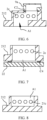
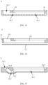
- FIG. 3 is a cross-sectional view of a first embodiment of the electronic device shown in FIG. 1 in a P-P direction
- FIG. 4 is a front view of a partial structure of FIG. 3
- FIG. 5 is a cross-sectional view of a first embodiment of the electronic device shown in FIG. 1 in a Q-Q direction.
- the second housing 2 is provided with a first sound outlet cavity 2a and a second sound outlet cavity 2b that are separate from each other, and the first sound outlet cavity 2a and the second sound outlet cavity 2b are spaced apart in the X-axis direction.
- the second housing 2 is further provided with a first sound outlet hole 2c and a second sound outlet hole 2d.
- the first sound outlet hole 2c is in communication with the first sound outlet cavity 2a
- the second sound outlet hole 2d is in communication with the second sound outlet cavity 2b.
- the speaker module 8 includes a first sound emitting portion 81 and a second sound emitting portion 82.
- the first sound emitting portion 81 faces the first housing 1, and the second sound emitting portion 82 faces the screen 22.
- a direction in which the first sound emitting portion 81 and the second sound emitting portion 82 are arranged opposite to each other is an axial direction of the speaker module 8.
- the axial direction may be parallel to the Z-axis direction, or may form an angle less than 90 degrees with the Z-axis direction, that is, the speaker module 8 may be arranged at a certain angle relative to the Z-axis direction.
- the axial direction of the speaker module 8 may be parallel to the Z-axis direction, to reduce a mounting space occupied by the speaker module 8 in the Z-axis direction.
- the first sound emitting portion 81 and the second sound emitting portion 82 may specifically be diaphragms, and both may vibrate and produce sounds. A specific mechanism of vibrating and producing sounds will not be described in detail herein.
- the speaker bracket 9 is provided with a communication cavity 9a. At least part of the communication cavity 9a extends along the X-axis direction.
- the speaker bracket 9 has a first connecting end and a second connecting end. The first connecting end and the second connecting end may be spaced apart in the X-axis direction, and the first connecting end may be sealingly assembled to the first sound emitting portion 81, so that the first sound emitting portion 81 can emit a sound wave into the communication cavity 9a.
- the second connecting end may be sealingly assembled to the second housing 2, so that the communication cavity 9a and the first sound outlet cavity 2a are in sealed communication.
- At least part of the communication cavity 9a may extend in the X-axis direction to have a first connecting end and a second connecting end that are spaced apart in the X-axis direction, so that the first sound emitting portion 81 and the first sound outlet cavity 2a that are spaced apart in the X-axis direction can be connected.
- the first sound outlet cavity 2a and the communication cavity 9a combine to form a front cavity of the first sound emitting portion 81, which is hereinafter referred to as a first front cavity; and the second sound outlet cavity 2b forms a front cavity of the second sound emitting portion 82, which is hereinafter referred to as a second front cavity.
- the first front cavity substantially extends in the X-axis direction
- the second front cavity is located on a side of the speaker module 8 in the Z-axis direction.
- This layout arrangement can reduce a space occupied in the Y-axis direction of the electronic device 100 and can better reduce the mounting space occupied by the speaker module 8 in the Y-axis direction, thereby adapting to mounting of more types of models.
- FIG. 6 is a schematic diagram of a structure of another mounting method of a second sealing portion.
- FIG. 7 is a schematic diagram of a structure of a modification solution of a first hole portion shown in FIG. 4 .
- FIG. 8 is a schematic diagram of a structure of another modification solution of a first hole portion shown in FIG. 4 .
- a bump 212g is arranged on the side of the middle plate 212 that faces the first housing 1.
- the bump 212g is configured to process the foregoing first hole portion A1 and to form the first sound outlet cavity 2a.
- a size of the remaining region of the middle plate 212 except for the position at which the bump 212g is arranged may be smaller in the Z-axis direction, which is beneficial to the lightweight design of the middle plate 212.
- the first hole section A11 may be formed on the bump.
- the positioning plate 212d and the middle plate 212 may be in an integrated structure. Alternatively, the positioning plate 212d and the middle plate 212 may be manufactured separately and then assembled. A specific assembly method includes but is not limited to welding, riveting, screwing, bonding, snapping, or the like.
- the speaker module 8 may abut against the frame 211. In this way, a quantity of positioning plates 212d used may be reduced. Certainly, in the Y-axis direction, the speaker module 8 may alternatively be arranged with a gap from the frame 211.
- the middle plate 212 may be provided with a fourth hole portion B1, and the second sound outlet cavity 2b may include an inner space of the fourth hole portion B1.
- the second sound emitting portion 82 may be connected to the fourth hole portion B1 to emit a sound into the fourth hole portion B1.
- An axial direction of the fourth hole portion B1 may be parallel to the Z-axis direction, or may be arranged at an angle to the Z-axis direction.
- the second sound outlet hole 2d being a long slit
- FIG. 11 The implementation of the second sound outlet hole 2d including a plurality of short slits, reference may be made to FIG. 12 .
- the second sound outlet hole 2d forms a sound outlet region in the X-axis direction.
- a size of the sound outlet region in the X-axis direction is larger than that of the fourth hole portion B1.
- the transition space may communicate with the second sound outlet hole 2d and the fourth hole portion B1, and the second sound outlet cavity 2b may include the transition space.
- the transition space may be gradually expanded along a direction close to the second sound outlet hole 2d, so that a size transition between a sound region of the second sound outlet hole 2d and the fourth hole portion B1 may be formed, which can better avoid sudden changes in size, thereby improving the sound playback quality.
- the transition space may be formed by cutting the middle plate 212 or cutting the screen 22.
- the surface of the middle plate 212 that faces the screen 22 may be provided with a transition slot 212b.
- the transition slot 212b may cooperate with the screen 22 to enclose the foregoing transition space.
- the second sound outlet hole 2d may alternatively be provided on the frame 211. In this case, the second sound outlet hole 2d may be moved away from the screen 22.
- a possibility of the glue blocking the second sound outlet hole 2d may be avoided to a large extent.
- the solution of arranging the second sound outlet hole 100b on the frame 211 and the solution of arranging the second sound outlet hole 100b between the screen 22 and the frame 211 may be adopted. That is to say, the second sound outlet hole 100b may be arranged at two positions.
- FIG. 13 is a schematic diagram of a structure of an implementation of a speaker bracket
- FIG. 14 is a cross-sectional view of FIG. 13
- FIG. 15 is a cross-sectional view of a modification solution of the speaker bracket shown in FIG. 13 .
- extending directions of the first sub-cavity 9a-1 and the third sub-cavity 9a-3 may alternatively be arranged at an angle with the Z-axis direction, and the second sub-cavity 9a-2 may alternatively only partially extend in the X-axis direction.
- the entire communication cavity 9a may extend along an arc direction. That is to say, the structural form of the communication cavity 9a is not actually unique. In a specific implementation, those skilled in the art can adjust it according to actual requirements, as long as the requirements of use can be met.
- the first sub-cavity 9a-1 is connected to the first sound emitting portion 81, and a size of the first sub-cavity 9a-1 is related to a size of the first sound emitting portion 81.
- a size of a cross-section perpendicular to an axial direction of the first sub-cavity 9a-1 is basically determined.
- a cross-section perpendicular to an axial direction of the third sub-cavity 9a-3 has more design space.
- an area of the cross-section perpendicular to the axial direction of the third sub-cavity 9a-3 may be designed to be smaller than the area of the cross-section perpendicular to the axial direction of the first sub-cavity 9a-1. In this way, the size of the speaker bracket 9 in the X-axis direction and the Y-axis direction may be relatively small, and the mounting space occupied by the speaker bracket 9 may further be reduced.
- an opening of the first hole portion A1 connected to the third sub-cavity 9a-3 may also be smaller, which can further reduce an opening area of the middle plate 212 and reduce the impact of the opening on the strength of the middle plate 212, thereby ensuring the overall structural strength of the middle frame 21.
- the end of the speaker bracket 9 that faces the first sound emitting portion 81 forms a first connecting end.
- a first sealing portion C1 is provided between the first connecting end and the first sound emitting portion 81.
- the second sealing surface 94 may be a flat surface, a conical surface, a spherical surface, or the like.
- the first connecting end may include the foregoing first sealing surface 93 and the second sealing surface 94.
- the first sealing surface 93 and the second sealing surface 94 may be selected for the first connecting end.
- the first connecting end may only be provided with the first sealing surface 93. Due to elimination of the second sealing surface 94, the sizes of the speaker bracket 9 in both the X-axis direction and the Y-axis direction may be reduced, further reducing the mounting space occupied by the speaker module 8.
- the first connecting end may be provided with only the second sealing surface 94.
- a portion framed by a dotted line shown in FIG. 15 may be removed, so that the size of the second sub-cavity 9a-2 in the Z-axis direction may be relatively great, obstruction in the extending direction of the communication cavity 9a may be relatively small, the eddy current formed in the sound wave transmission process may be relatively small, and the sound playback quality may be high.
- FIG. 16 is a cross-sectional view of another modification solution of the speaker bracket shown in FIG. 13 .
- the speaker bracket 9 may be in a split structure and includes a bottom plate portion 91 and a frame portion 92, the frame portion 92 may be provided with a first through hole 921 and a second through hole 922, and the bottom plate portion 91 may be mounted on an axial end of the frame portion 92.
- the bottom plate portion 91 and the frame portion 92 may enclose the first sub-cavity 9a-1, the second sub-cavity 9a-2, and the third sub-cavity 9a-3, the first sub-cavity 9a-1 includes an inner space of the first through hole 921, and the third sub-cavity 9a-3 includes an inner space of the second through hole 922.
- the foregoing split design may facilitate the processing of the speaker bracket 9 and the formation of the communication cavity 9a, especially the formation of the communication cavity 9a with a complex structure.
- FIG. 17 is a cross-sectional view of still another modification solution of the speaker bracket shown in FIG. 13 .
- the speaker bracket 9 may alternatively be an integrated structure.
- inner wall surfaces of the first sub-cavity 9a-1, the second sub-cavity 9a-2, and the third sub-cavity 9a-3 may be provided with an easy demoulding bevel 9a-4 to facilitate the integral molding of the speaker bracket 9.
- a quantity and a setting position of inclined surfaces for easy demoulding 9a-4 are not limited herein. In a specific implementation, those skilled in the art may design according to actual requirements.
- a projection of the second sub-cavity 9a-2 on the second housing 2 along the thickness direction may be set to be L-shaped to avoid the camera module.
- the first sub-cavity 9a-1, the second sub-cavity 9a-2, and the third sub-cavity 9a-3 may be arranged around an outer side of the camera hole 212c.
- first sound outlet cavity 2a may also be adjusted to avoid components that may interfere.
- FIG. 21 is a diagram of a partial structure of a side of a middle frame facing away from a first housing in a third embodiment of the electronic device shown in FIG. 1
- FIG. 22 is a schematic diagram of a structure of orthographic projections of a second hole portion and a third hole portion shown in FIG. 21 on the middle plate
- FIG. 23 is a cross-sectional view of the second hole portion and the third hole portion shown in FIG. 22 on a line R.
- the middle plate 212 may be provided with a second hole portion A2 and a third hole portion A3 that are in communication with each other, and the first sound outlet cavity 2a may include inner spaces of the second hole portion A2 and the third hole portion A3.
- Two axial ends of the second hole portion A2 may be in a blocked state, an end of the third hole portion A3 that faces away from the first housing 1 may be in the blocked state, and an end of the third hole portion A3 that faces the first housing 1 may be in communication with the communication cavity 9a.
- the first sound outlet hole 2c is arranged on the frame 211, and the first sound outlet hole 2c is in communication with the second hole portion A2.
- orthographic projections of the second hole portion A2 and the third hole portion A3 on the middle plate 212 may be in a Z-shape to avoid the camera module that may interfere.
- the projections of the second hole portion A2 and the third hole portion A3 are not limited to the foregoing Z-shape, as long as the projections do not extend on the same straight line, so that the components that may interfere may be avoided.
- the foregoing descriptions of the second sub-cavity 9a-2 refer to the foregoing descriptions of the second sub-cavity 9a-2, and no repeated description is made herein.
- the end of the second hole portion A2 that faces the first housing 1 may also be blocked by the blocking component.
- the second hole portion A2 may also be directly configured as a blind hole, so that the end of the second hole portion A2 that faces the first housing 1 may naturally be in the blocked state.
- the second hole portion A2 may include a third hole section A21 and a fourth hole section A22 that are in communication with each other, where the third hole section A21 may be directly in communication with the first sound outlet hole 2c, and the second hole section A12 may be configured to communicate with the first hole section A21 and the third hole portion A3.
- the third hole section A21 and the third hole portion A3 are also arranged in a certain position.
- the fourth hole section A22 connecting the third hole section A21 and the third hole portion A3 is an adjustable hole section, and the extending direction on the middle plate 212 may have a variety of choices to meet the design of different forms of products.
- the size of the fourth hole section A22 in the Z-axis direction may be set to be smaller than that of the third hole section A21, that is, the fourth hole section A22 may be set shallower, to reduce the digging volume of the middle plate 212, thereby reducing the impact on the strength of the middle plate 212, so that the middle frame 21 can have a relatively high structural strength.
- FIG. 24 is a diagram of a partial structure of a side of a middle frame facing a first housing in a fourth embodiment of the electronic device shown in FIG. 1
- FIG. 25 is a diagram of a connecting structure of a first sealing end surface of the middle frame shown in FIG. 24 and a speaker bracket.
- the first sound outlet cavity 2a may further be arranged on the frame 211, and the first sound outlet hole 2c may also be arranged on the frame 211.
- the second connecting end of the speaker bracket 9 may be directly connected to the frame 211 and connect the communication cavity 9a to the first sound outlet cavity 2a.
- the frame 211 has a first sealing end surface 211b, and the second connecting end has a second sealing end surface 95.
- the foregoing second sealing portion C2 may be arranged between the first sealing end surface 211b and the second sealing end surface 95 to achieve sealing at the connection position between the communication cavity 9a and the first sound outlet cavity 2a.
- the first sealing end surface 211b and the second sealing end surface 95 may be parallel. In implementations of FIG. 24 and FIG. 25 , both the first sealing end surface 211b and the second sealing end surface 95 may be arranged at an angle with the Z-axis direction. In some other embodiments, the first sealing end surface 211b and the second sealing end surface 95 may also be parallel to the Z-axis direction and perpendicular to the Y-axis direction. The first sealing end surface 211b and the second sealing end surface 95 may also form a certain angle. These are all feasible in specific practice.
- the first sound outlet cavity 2a may not exist.
- the communication cavity 9a may be directly in communication with the first sound outlet hole 2c.
- the second sound outlet cavity 2b may not exist.
- the second sound emitting portion 82 directly emits a sound through the second sound outlet hole 2d.
- the speaker bracket 9 may alternatively be mounted on the main board bracket 31.
- the mounting method between the speaker bracket 9 and the main board bracket 31 includes but is not limited to screwing, bonding, welding, snapping, riveting, or the like, as long as the reliable connection can be ensured.
- the speaker bracket 9 and the main board bracket 31 may alternatively be of an integrated structure. In this way, a quantity of internal components of the electronic device 100 may further be reduced to simplify the mounting process of the electronic device 100.
- the speaker bracket 9 may alternatively directly abut against the first housing 1 in the Z-axis direction.
- the main board bracket 31 may be provided with an escape hole for avoiding the speaker module 8 and the speaker bracket 9.
- the main board bracket 31 may be arranged at a position avoiding the speaker module 8 and the speaker bracket 9.
- the speaker module 8 and the speaker bracket 9 may be collectively referred to as a speaker assembly, and the main board bracket 31 may be located on a side of the speaker assembly in the X-axis direction or the Y-axis direction to avoid mounting interference.
- the speaker module 8 may include a first sound emitting portion 81 and a second sound emitting portion 82. At least one of the first sound emitting portion 81 and the second sound emitting portion 82 may further be provided with a dustproof net 83 for reducing the impact of dust on the two sound emitting portions.
- a gap may be provided between the dustproof net 83 and the second sound emitting portion 82, which can largely prevent the second sound emitting portion 82 from flapping the dustproof net 83 during vibration and the dustproof net 83 from being broken and/or the second sound emitting portion 82 from being damaged, and is beneficial to ensure the service life of the second sound emitting portion 82 and the dustproof net 83.
- the dustproof net 83 may not be directly arranged on the speaker module 8.
- the dustproof net 83 may alternatively be arranged at other positions, such as the connection position between the second connecting end and the second housing 2, and specifically may be fixedly assembled through the foregoing sealing portion.
- the second sealing portion C2 may be sealant, and the dustproof net 83 arranged between the second connecting end and the second housing 2 may be fixed through the second sealing portion C2.
- the speaker module 8 is further configured with a rear cavity, and the rear cavity may be a closed rear cavity to reduce the impact on other structural components 100 inside the electronic device.
- the rear cavity may be arranged inside the speaker bracket 9, or may be formed by all or part of the speaker bracket 9, the middle frame 21, the first housing 1, the main board bracket 31, and other components.
- the foregoing rear cavity may alternatively be an open rear cavity.
- the speaker module 8 and the speaker bracket 9 are usually connected first to form a speaker assembly, and then the speaker assembly is mounted on the second housing 2.
- the communication cavity of the speaker bracket does not extend in the X-axis direction, but an opening extending in the Y-axis direction is directly provided, and then directly connects the communication cavity along the Y-axis direction to the first sound outlet hole 2c on the frame 211, and connects the second sound emitting portion 82 in the Z-axis direction to the middle plate.
- a second sealing portion C2 is arranged between the speaker bracket 9 and the frame 211, and a third sealing portion C3 is arranged between the speaker module and the middle plate.
- the mounting direction of the speaker assembly includes the Y-axis direction and the Z-axis direction.
- the second sealing portion C2 and the third sealing portion C3 may be damaged, which is not conducive to ensuring reliable of the speaker assembly, and sound leakage may occur.
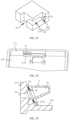
- FIG. 27 is a cross-sectional view of a fifth embodiment of the electronic device shown in FIG. 1 in a Q-Q direction
- FIG. 28 is a front view of a partial structure in FIG. 27
- FIG. 29 is a diagram of a mounting structure of a speaker bracket and a middle frame in the electronic device shown in FIG. 27
- FIG. 30 is a schematic diagram of a structure of a modification solution of FIG. 29 .
- the speaker bracket 9 is configured with a guide portion 96
- the guide portion 96 is configured with a first guide surface 961 and a second guide surface 962, where the first guide surface 961 and the Y-axis direction form an angle of less than 90 degrees, and the second guide surface 962 and the Z-axis direction form an angle of less than 90 degrees.
- the second housing 2 is provided with a guide groove 23, and the guide groove 23 has a first matching surface 231 and a second matching surface 232.
- Extending directions of the first guide surface 961 and the first matching surface 231 are consistent, and extending directions of the second guide surface 962 and the second matching surface 232 may be consistent, so that after assembly, the first guide surface 961 may be fitted with the first matching surface 231, and the second guide surface 962 may be fitted with the second matching surface 232.
- the guide portion 96 before the guide portion 96 enters the guide groove 23, the guide portion 96 cooperates with the middle plate 212 and the frame 211 to support the speaker assembly to prevent the speaker bracket 9 from being in contact with the second sealing portion C2 and the third sealing portion C3.
- the speaker assembly may gradually press the second sealing portion C2 in the Y-axis direction, and gradually press the third sealing portion C3 in the Z-axis direction, which not only ensures the reliability of the connection, but also reduces the possibility of damage to the second sealing portion C2 and the third sealing portion C3.
- the guide portion 96 may only be provided with the first guide surface 961.
- the guide groove 23 may be provided with only the first matching surface 231.
- the speaker assembly may be assembled close to the frame 211 along the Y-axis direction. Specifically, when the guide portion 96 does not enter the guide groove 23, the guide portion 96 may form a support with the middle plate 212 to prevent the speaker assembly from scratching or scraping the third sealing portion C3. After the guide portion 96 enters the guide groove 23, through guide cooperation between the first guide surface 961 and the first matching surface 231, the speaker assembly may gradually press the second sealing portion C2 in the Y-axis direction, and gradually press the third sealing portion C3 in the Z-axis direction.
- the guide portion 96 may also be provided on the second housing 2, and the guide groove 23 may also be provided on the speaker bracket 9.
- the second sealing portion C2 may also be pressed between the speaker bracket 9 and the frame 211 along the X-axis direction.
- the first guide surface 961 may also be arranged at an angle with the X-axis direction.
Landscapes
- Engineering & Computer Science (AREA)
- Signal Processing (AREA)
- Physics & Mathematics (AREA)
- Theoretical Computer Science (AREA)
- Acoustics & Sound (AREA)
- Computer Hardware Design (AREA)
- Human Computer Interaction (AREA)
- General Engineering & Computer Science (AREA)
- General Physics & Mathematics (AREA)
- Health & Medical Sciences (AREA)
- Otolaryngology (AREA)
- Details Of Audible-Bandwidth Transducers (AREA)
Abstract
Description
- This application claims priority to
Chinese Patent Application No. 202210815072.6, filed with the Chinese National Intellectual Property Administration on July 12, 2022 - Embodiments of this application relate to the field of electronic device technologies, and in particular, to an electronic device configured with a speaker module.
- A speaker module is configured to restore an audio electrical signal such as music and speech into a sound, has a function of supporting audio external playback, and is increasingly widely used in an electronic device such as a mobile phone or a tablet computer.
- Using a mobile phone as an example, with continuous development of society and continuous improvement of user requirements, more devices are integrated into the mobile phone, causing a space inside an electronic device to become increasingly tight. However, in a conventional solution, a speaker module occupies a large space in a longitudinal direction of the mobile phone during assembly. As a result, the speaker module is unable to be mounted in some types of mobile phones.
- Therefore, how to provide a solution to overcome or alleviate the foregoing defects is still a technical problem to be urgently solved by those skilled in the art.
- Embodiments of this application provide an electronic device. A speaker module in the electronic device occupies a small space in a longitudinal direction and can be adapted to assembly of an electronic device with a limited longitudinal space.
- According to a first aspect, an embodiment of this application provides an electronic device, and the electronic device may specifically be a mobile phone, a tablet computer, and the like. The electronic device includes a first housing, a second housing, a speaker module, and a speaker bracket. The first housing and the second housing are connected to each other along a thickness direction of the electronic device, and can form an external structure of the electronic device. The second housing is further provided with a first sound outlet hole and a second sound outlet hole. The speaker module includes a first sound emitting portion and a second sound emitting portion, the first sound emitting portion faces the first housing, and the second sound emitting portion faces the second housing. The speaker bracket is provided with a communication cavity, and at least part of the communication cavity extends along a transverse direction of the electronic device. The speaker bracket has a first connecting end and a second connecting end spaced apart in the transverse direction of the electronic device. The first connecting end is sealing assembled to the first sound emitting portion, so that the first sound emitting portion is capable of emitting a sound wave into the communication cavity, and the second connecting end is sealing assembled to the second housing, so that the communication cavity is in communication with the first sound outlet hole. The second sound emitting portion is assembled to the second housing, so that the second sound emitting portion is capable of emitting a sound wave into the second sound outlet hole.
- By using this solution, the speaker module and the speaker bracket are arranged in the thickness direction of the electronic device, and at least part of the communication cavity of the speaker bracket extends in the transverse direction of the electronic device, so that the first connecting end and the second connecting end are spaced apart in the transverse direction of the electronic device. This layout method can make full use of a transverse space of the electronic device to reduce occupation on a longitudinal space of the electronic device, and can better reduce a mounting space occupied by the speaker module in the longitudinal direction, thereby better adapting to the mounting of the electronic device with a limited longitudinal space.
- It can be understood that for an electronic device with a sufficient longitudinal space, when the foregoing solution is adopted, since the speaker module occupies less mounting space in the longitudinal direction, there may be excess longitudinal space in the electronic device, and the excess longitudinal space may further be used to mount other components, so that more components can exist in the longitudinal direction of the electronic device.
- That is to say, the solution provided in embodiments of this application may be applied to the electronic device with a relatively limited longitudinal space, or may be applied to the electronic device with a relatively sufficient longitudinal space, and types of electronic devices to which the solution is adapted may further increase.
- Based on the first aspect, this embodiment of this application further provides a first implementation of the first aspect: the second housing may further be provided with a first sound outlet cavity, and the first sound outlet cavity is configured to communicate the first sound outlet hole and the communication cavity. The first sound outlet cavity can form a buffer space between the communication cavity and the first sound outlet hole to guide the sound wave in the communication cavity to the first sound outlet hole for playback, which is beneficial to reducing eddy currents during sound wave transmission and reducing noise, thereby ensuring a better sound playback quality.
- In specific practice, the first sound outlet cavity may not be provided. In this case, the communication cavity may be directly in communication with the first sound outlet hole.
- Based on the first implementation of the first aspect, this embodiment of this application further provides a second implementation of the first aspect: the second housing includes a middle frame, the middle frame includes a frame and a middle plate, the middle plate is provided with a first hole portion, an inner space of the first hole portion forms the first sound outlet cavity, an end of the first hole portion that faces away from the first housing is in a blocked state, an end of the first hole portion that faces the first housing is in communication with the communication cavity, and the first sound outlet hole is provided on the frame.
- Based on the second implementation of the first aspect, this embodiment of this application further provides a third implementation of the first aspect: the first hole portion is a blind hole. In this way, the end of the first hole portion that faces away from the first housing may be naturally in a blocked state, without the need for an additional blocking component, and a structure of the electronic device may be relatively simple. In addition, in the blind hole solution, the middle plate does not need to be penetrated, a digging volume of the middle plate may be relatively small, and opening of the first hole portion may also have less impact on a strength of the middle plate, thereby ensuring the overall strength of the middle frame to a greater extent.
- Based on the second implementation of the first aspect, this embodiment of this application further provides a fourth implementation of the first aspect: the first hole portion is a through hole, the second housing further includes a blocking component, and the blocking component is configured to block the end of the first hole portion that faces away from the first housing.
- Based on the fourth implementation of the first aspect, this embodiment of this application further provides a fifth implementation of the first aspect: the second housing further includes a screen, the screen is mounted on a side of the middle plate that faces away from the first housing, and the blocking component is the screen. The screen is a component of the electronic device. By using the screen as the blocking component, a quantity of components may be reduced, thereby simplifying the structure of the electronic device.
- Based on the fourth implementation or the fifth implementation of the first aspect, this embodiment of this application further provides a sixth implementation of the first aspect: the first hole portion includes a first hole section and a second hole section that are in communication with each other, the first hole section is in communication with the communication cavity, an end of the second hole section away from the first housing is blocked by the blocking component, and the first hole section and the second hole section are not coaxial.
- By using this solution, an opening area of the first hole portion on a surface of the middle plate that faces the first housing and an opening area of a surface that faces the screen may be smaller, which can reduce an inner space of the first hole portion, thereby further reducing the impact on the strength of the middle plate. In addition, since the opening area of the first hole portion on the surface of the middle plate that faces the first housing (that is, the opening area of the first hole section) may be smaller, correspondingly, a size of the second connecting end connected to the first hole section in the transverse direction of the electronic device may also be smaller, and a size of the speaker bracket in the transverse direction of the electronic device may also be reduced, thereby reducing the mounting space occupied by the speaker module in the transverse direction of the electronic device to a certain extent. In addition, for the first hole portion, the foregoing design only makes sizes of two end portions of the first hole portion in the thickness direction relatively small, a size of a middle region (a communication region between the first hole section and the second hole section) of the first hole portion in the thickness direction may still be great, and a size of a sound outlet region of the first sound outlet hole in the transverse direction of the electronic device is not affected substantially.
- Based on the first implementation of the first aspect, this embodiment of this application further provides a seventh implementation of the first aspect: the second housing includes a middle frame, the middle frame includes a frame, and the frame is provided with the first sound outlet cavity and the first sound outlet hole.
- Based on the seventh implementation of the first aspect, this embodiment of this application further provides an eighth implementation of the first aspect: the frame is provided with a first sealing end surface surrounding the first sound outlet cavity, the first sealing end surface is arranged at an angle with the thickness direction, the second connecting end has a second sealing end surface, and the first sealing end surface is sealingly assembled with the second sealing end surface. In this solution, the assembly of the first sealing end surface and the second sealing end surface is a bevel connection. An assembly process is relatively simple, and it is not easy to cause damage to a sealing portion between the two sealing end surfaces.
- Based on the first implementation of the first aspect, this embodiment of this application further provides a ninth implementation of the first aspect: the second housing includes a middle frame, the middle frame includes a frame and a middle plate, the middle plate is provided with a second hole portion and a third hole portion that are in communication with each other, the first sound outlet cavity includes inner spaces of the second hole portion and the third hole portion, two axial ends of the second hole portion are in a blocked state, an end of the third hole portion that faces away from the first housing is in the blocked state, and an end of the third hole portion that faces the first housing is in communication with the communication cavity; and the first sound outlet hole is provided on the frame and is in communication with the second hole portion.
- Based on the ninth implementation of the first aspect, this embodiment of this application further provides a tenth implementation of the first aspect: the second hole portion is a blind hole. In this way, the end of the second hole portion that faces the first housing may be naturally in the blocked state. There is no need to provide a special blocking component, which can reduce the quantity of components of the electronic device, simplify the structure of the electronic device, and can further reduce the impact on the strength of the middle plate; an opening end of the second hole portion faces away from the first housing, and the third hole portion is a through hole; and the second housing further includes a blocking component, and the blocking component is configured to block ends of the second hole portion and the third hole portion that face away from the first housing.
- Based on the tenth implementation of the first aspect, this embodiment of this application further provides an eleventh implementation of the first aspect: the second housing further includes a screen, the screen is mounted on a side of the middle plate that faces away from the first housing, and the blocking component is the screen. The screen is a component of the electronic device. By using the screen as the blocking component, a quantity of components may be reduced, thereby simplifying the structure of the electronic device.
- Based on the tenth implementation or the eleventh implementation of the first aspect, this embodiment of this application further provides a twelfth implementation of the first aspect: the second hole portion includes a third hole section and a fourth hole section that are in communication with each other, the third hole section is in communication with the first sound outlet hole, the fourth hole section is in communication with the third hole portion, and a size of the third hole section along the thickness direction is larger than that of the fourth hole section. In this arrangement, the fourth hole section may be set shallower, which can reduce the digging volume of the middle plate, thereby reducing the impact on the strength of the middle plate, so that the middle frame can have a relatively high structural strength.
- Based on any one of the ninth implementation to the twelfth implementation of the first aspect, this embodiment of this application further provides a thirteenth implementation of the first aspect: orthographic projections of the second hole portion and the third hole portion on the middle plate do not extend on a same straight line. In this way, a position of the third hole portion can be easily adjusted, thereby adapting to the assembly of different electronic devices, especially in a situation in which an interfering component may exist. For example, in a mounting situation in which the speaker module and the camera module interfere, the foregoing solution can better achieve avoidance between the speaker module and the camera module in a mounting process.
- A specific extending direction of the foregoing orthographic projection is not limited herein, and can be determined based on a specific structure of the electronic device in a practical application.
- Based on the first aspect or based on any one of the first implementation to the thirteenth implementation of the first aspect, this embodiment of this application further provides a fourteenth implementation of the first aspect: the communication cavity includes a first sub-cavity, a second sub-cavity, and a third sub-cavity that are in communication in sequence; the first sub-cavity is connected to the first sound emitting portion and is configured to directly receive a vibrating sound of the first sound emitting portion; at least part of the second sub-cavity extends along the transverse direction of the electronic device to achieve a transverse extension design of the communication cavity; and the third sub-cavity may be in communication with the first sound outlet hole, so that the sound produced by the first sound emitting portion can be played through the first sound outlet hole.
- In fact, the communication cavity may also be V-shaped as a whole. In this case, it can be considered that the communication cavity only includes two sub-cavities.
- Based on the fourteenth implementation of the first aspect, this embodiment of this application further provides a fifteenth implementation of the first aspect: an area of a cross-section of the third sub-cavity perpendicular to an axial direction of the third sub-cavity is smaller than an area of a cross-section of the first sub-cavity perpendicular to an axial direction of the first sub-cavity. In this way, sizes of the speaker bracket in the transverse direction and the longitudinal direction of the electronic device may be relatively small, and the mounting space occupied by the speaker bracket may further be reduced. In addition, since the area of the cross-section perpendicular to the axial direction of the third sub-cavity is smaller, correspondingly, an opening of the first hole portion connected to the third sub-cavity may also be smaller, which can further reduce an opening area of the middle plate and reduce the impact of the opening on the strength of the middle plate, thereby ensuring the overall structural strength of the middle frame.
- Based on the fourteenth implementation or the fifteenth implementation of the first aspect, this embodiment of this application further provides a sixteenth implementation of the first aspect: the speaker bracket includes a bottom plate portion and a frame portion that are separate, the frame portion is provided with a first through hole and a second through hole, the bottom plate portion is mounted on an axial end of the frame portion, the bottom plate portion and the frame portion enclose the first sub-cavity, the second sub-cavity, and the third sub-cavity, the first sub-cavity includes an inner space of the first through hole, and the third sub-cavity includes an inner space of the second through hole. The split design of the speaker bracket can facilitate formation of a communication cavity with a complex extending direction.
- Based on the fourteenth implementation or the fifteenth implementation of the first aspect, this embodiment of this application further provides a seventeenth implementation of the first aspect: the speaker bracket is of an integrated structure, and inner wall surfaces of the first sub-cavity, the second sub-cavity, and the third sub-cavity are provided with an easy demoulding bevel to facilitate demolding, thereby facilitating the formation of the communication cavity with the complex extending direction.
- Based on any one of the fourteenth implementation to the seventeenth implementation of the first aspect, this embodiment of this application further provides an eighteenth implementation of the first aspect: a projection of the second sub-cavity on the second housing along the thickness direction does not extend on a same straight line. In this arrangement, a position of the second connecting end can also be easily adjusted, thereby adapting to the assembly of different electronic devices, especially in a situation in which an interfering component may exist. For example, in a mounting situation in which the speaker module and the camera module interfere, the foregoing solution can better achieve avoidance between the speaker module and the camera module in a mounting process.
- Based on the eighteenth implementation of the first aspect, this embodiment of this application further provides a nineteenth implementation of the first aspect: the second housing includes a middle frame, the middle frame includes a frame and a middle plate, the middle plate is provided with a camera hole, the camera hole is configured to be used with the camera module of the electronic device, and the first sub-cavity, the second sub-cavity, and the third sub-cavity are arranged surrounding the camera hole to avoid the camera module.
- Based on any one of the fourteenth implementation to the nineteenth implementation of the first aspect, this embodiment of this application further provides a twentieth implementation of the first aspect: the first connecting end has a first sealing surface, a direction in which the first sound emitting portion and the second sound emitting portion are arranged opposite to each other is an axial direction of the speaker module, the first sealing surface is perpendicular to the axial direction of the speaker module, and the first sound emitting portion is sealingly mounted on the first sealing surface. In this case, a sealing form between the first sound emitting portion and the first sealing surface may be dispensing, gum, or a combination of dispensing and gum.
- Based on the fourteenth implementation or the nineteenth implementation of the first aspect, this embodiment of this application further provides a twenty-first implementation of the first aspect: the first connecting end has a second sealing surface, a direction in which the first sound emitting portion and the second sound emitting portion are arranged opposite to each other is an axial direction of the speaker module, the second sealing surface and the axial direction of the speaker module are arranged at an angle, the angle is less than 90 degrees, and the first sound emitting portion is sealingly mounted on the second sealing surface. In this case, a sealing form between the first sound emitting portion and the second sealing surface may be gum.
- The first sealing surface and the second sealing surface may be used selectively, or both may be arranged.
- Based on the first aspect or based on any one of the first implementation to the twenty-first implementation of the first aspect, this embodiment of this application further provides a twenty-second implementation of the first aspect: the electronic device may further include a main board bracket; and the main board bracket may be press-connected to the speaker bracket toward the second housing to prevent the speaker bracket from lifting after mounting, which can improve the mounting reliability of the speaker bracket, thereby improving the mounting reliability of the speaker module; or the speaker bracket may also be mounted on the main board bracket; or the speaker bracket and the main board bracket may be of an integrated structure. In this way, a quantity of components may be reduced and the mounting process of the electronic device may be simplified.
- Based on the first aspect or based on any one of the first implementation to the twenty-second implementation of the first aspect, this embodiment of this application further provides a twenty-third implementation of the first aspect: the second housing is further provided with a plurality of positioning plates for positioning and assembling the speaker module in the transverse direction and the longitudinal direction of the electronic device, which can improve the mounting reliability of the speaker module in the second housing.
- Based on the first aspect or based on any one of the first implementation to the twenty-third implementation of the first aspect, this embodiment of this application further provides a twenty-fourth implementation of the first aspect: the second housing is provided with a second sound outlet cavity, the second sound outlet cavity is in communication with the second sound outlet hole, and the second sound outlet cavity is connected to the second sound emitting portion, so that the second sound emitting portion can emit a sound wave to the second sound outlet cavity. The second sound outlet cavity can form a buffer space between the communication cavity and the second sound outlet hole to guide the sound wave in the communication cavity to the second sound outlet hole for playback, which is beneficial to reducing eddy currents during sound wave transmission and reducing noise, thereby ensuring a better sound playback quality.
- Based on the twenty-fourth implementation of the first aspect, this embodiment of this application further provides a twenty-fifth implementation of the first aspect: the second housing includes a middle frame and a screen, the middle frame includes a frame and a middle plate, the screen is mounted on a side of the middle plate that faces away from the first housing, the middle plate is provided with a fourth hole portion, and the second sound outlet cavity includes an inner space of the fourth hole portion; and the second sound outlet hole is provided on the frame, and/or the second sound outlet hole is provided between the frame and the screen.
- Based on the twenty-fifth implementation of the first aspect, this embodiment of this application further provides a twenty-sixth implementation of the first aspect: a transition space is further provided between the screen and the middle frame, the transition space connects the second sound outlet hole to the fourth hole portion, the second sound outlet cavity includes the transition space, and the transition space is gradually expanded along a direction close to the second sound outlet hole, so that a size transition between a sound region of the second sound outlet hole and the fourth hole portion may be formed, which can better avoid sudden changes in size, thereby improving the sound playback quality.
- Based on the first aspect or based on any one of the first implementation to the twenty-sixth implementation of the first aspect, this embodiment of this application further provides a twenty-seventh implementation of the first aspect: at least one of a connecting position between the speaker module and the first connecting end, a connecting position between the speaker module and the second housing, and a connecting position between the second connecting end and the second housing is provided with a dustproof net, so that anti-dust performance of the speaker module is improved.
- Based on the first aspect or based on any one of the first implementation to the twenty-seventh implementation of the first aspect, this embodiment of this application further provides a twenty-eighth implementation of the first aspect: the speaker module is further configured with a closed rear cavity, which can reduce the impact on other structural components inside the electronic device.
- Based on the first aspect or based on any one of the first implementation to the twenty-eighth implementation of the first aspect, this embodiment of this application further provides a twenty-ninth implementation of the first aspect: a main board is further included, the main board is connected to the speaker module through a signal, and the main board is configured to control the first sound emitting portion and the second sound emitting portion to emit sound waves in a same phase or in opposite phases.
- During specific work, the main board may control the first sound emitting portion and the second sound emitting portion to emit the sound waves in opposite phases respectively to offset sound leakage, thereby improving the privacy of calls. In an external playback scenario, the first sound emitting portion and the second sound emitting portion may also emit the sound waves in the same phase to enhance a stereo effect.
- According to a second aspect, an embodiment of this application provides an electronic device, and the electronic device may specifically be a mobile phone, a tablet computer, and the like. The electronic device includes a first housing, a second housing, a speaker module, and a speaker bracket. The speaker module and the speaker bracket are collectively referred to as a speaker assembly. The first housing and the second housing are connected to each other along a thickness direction of the electronic device, and can form an external structure of the electronic device. The second housing is further provided with a first sound outlet hole and a second sound outlet hole. The speaker module includes a first sound emitting portion and a second sound emitting portion, the first sound emitting portion faces the first housing, and the second sound emitting portion faces the second housing. The speaker bracket is provided with a communication cavity, and the speaker bracket has a first connecting end and a second connecting end. The first connecting end is sealingly assembled to the first sound emitting portion, so that the first sound emitting portion can emit a sound wave into the communication cavity. The second connecting end is sealingly assembled to the second housing along a first direction, so that the communication cavity is in communication with the first sound outlet hole. The second sound emitting portion is sealingly assembled to the second housing along a second direction, so that the second sound emitting portion can emit a sound wave into the second sound outlet hole. Sealing portions are provided between the second sound emitting portion and the second housing, and between the second connecting end and the second housing. The foregoing first direction is a longitudinal direction or a transverse direction of the electronic device, and the foregoing second direction is a thickness direction of the electronic device.
- One of the speaker bracket and the second housing is provided with a guide portion, and the other is provided with a guide groove. Before the guide portion enters the guide groove, the guide portion may play a supporting role, which can reduce scratches on the sealing portion in an assembly process; after the guide portion enters the guide groove, the mounting between the speaker bracket and the second housing, and the mounting between the second sound emitting portion and the second housing may be guided; and in the assembly process of the speaker assembly, relatively little damage may be done to the sealing portion, which is beneficial to ensuring the reliability of the sealing.
- Based on the second aspect, this embodiment of this application further provides a first implementation of the second aspect: the guide portion has a first guide surface, the first guide surface and the first direction form an angle of less than 90 degrees, the guide groove has a first matching surface, and extending directions of the first matching surface and the first guide surface are consistent. When the speaker assembly is assembled along the first direction, the first guide surface and the first matching surface may form a guide. After the assembly is completed, the first guide surface and the first matching surface may fit together.
- Based on the second aspect, this embodiment of this application further provides a second implementation of the second aspect: the guide portion has a second guide surface, the second guide surface and the second direction form an angle of less than 90 degrees, the guide groove has a second matching surface, and extending directions of the second matching surface and the second guide surface are consistent. When the speaker assembly is assembled along the second direction, the second guide surface and the second matching surface may form a guide. After the assembly is completed, the second guide surface and the second matching surface may fit together.
- Based on the second aspect, this embodiment of this application further provides a third implementation of the second aspect: a quantity of guide portions may be multiple, and correspondingly, a quantity of guide grooves may also be multiple, and the guide portions and the guide grooves may be assembled in one-to-one correspondence.
-
-
FIG. 1 is a schematic diagram of a structure of an electronic device according to this application; -
FIG. 2 is a schematic exploded diagram of the electronic device shown inFIG. 1 ; -
FIG. 3 is a cross-sectional view of a first embodiment of the electronic device shown inFIG. 1 in a P-P direction; -
FIG. 4 is a front view of a partial structure ofFIG. 3 ; -
FIG. 5 is a cross-sectional view of a first embodiment of the electronic device shown inFIG. 1 in a Q-Q direction; -
FIG. 6 is a schematic diagram of a structure of another mounting method of a second sealing portion; -
FIG. 7 is a schematic diagram of a structure of a modification solution of a first hole portion shown inFIG. 4 ; -
FIG. 8 is a schematic diagram of a structure of another modification solution of a first hole portion shown inFIG. 4 ; -
FIG. 9 is a schematic diagram of a partial structure of a side of a middle frame that faces a first housing shown inFIG. 4 ; -
FIG. 10 is a schematic diagram of a partial structure of a side of a middle frame that faces away from a first housing shown inFIG. 4 ; -
FIG. 11 is a schematic diagram of a structure of a specific implementation of a second sound outlet hole; -
FIG. 12 is a schematic diagram of a structure of another specific implementation of a second sound outlet hole; -
FIG. 13 is a schematic diagram of a structure of an implementation of a speaker bracket; -
FIG. 14 is a cross-sectional view ofFIG. 13 ; -
FIG. 15 is a cross-sectional view of a modification solution of the speaker bracket shown inFIG. 13 ; -
FIG. 16 is a cross-sectional view of another modification solution of the speaker bracket shown inFIG. 13 ; -
FIG. 17 is a cross-sectional view of still another modification solution of the speaker bracket shown inFIG. 13 ; -
FIG. 18 is a diagram of a mounting structure of a middle frame and a speaker module in a second embodiment of the electronic device shown inFIG. 1 ; -
FIG. 19 is a cross-sectional view of the middle frame and the speaker module shown inFIG. 18 after being configured with a speaker bracket; -
FIG. 20 is a cross-sectional view of the speaker bracket shown inFIG. 19 perpendicular to a Z-axis direction; -
FIG. 21 is a diagram of a partial structure of a side of a middle frame facing away from a first housing in a third embodiment of the electronic device shown inFIG. 1 ; -
FIG. 22 is a schematic diagram of a structure of orthographic projections of a second hole portion and a third hole portion shown inFIG. 21 on the middle plate; -
FIG. 23 is a cross-sectional view of the second hole portion and the third hole portion shown inFIG. 22 on a line R; -
FIG. 24 is a diagram of a partial structure of a side of a middle frame facing a first housing in a fourth embodiment of the electronic device shown inFIG. 1 ; -
FIG. 25 is a diagram of a connecting structure between a first sealing end surface of the middle frame shown inFIG. 24 and a speaker bracket; -
FIG. 26 is a schematic diagram of a structure of a speaker module; -
FIG. 27 is a cross-sectional view of a fifth embodiment of the electronic device shown inFIG. 1 in a Q-Q direction; -
FIG. 28 is a front view of a partial structure inFIG. 27 ; -
FIG. 29 is a diagram of a mounting structure of a speaker bracket and a middle frame in the electronic device shown inFIG. 27 ; and -
FIG. 30 is a schematic diagram of a structure of a modification solution ofFIG. 29 . - List of reference numerals in
FIG. 1 to FIG. 30 : - 100: electronic device;
- 1: first housing; 11: cover body; 12: camera decorative member;
- 2: second housing; 21: middle frame; 211: frame; 211a: socket; 211b: first sealing
end surface 212. middle plate; 212a: mounting slot; 212b: transition slot; 212c: camera hole; 212d: positioning plate; 212f: screen gum; 212g: bump; 22: screen; 221: light-transmissive cover plate; 222: panel; 23: guide groove; 231: first matching surface; 232: second matching surface; 2a: first sound outlet cavity; 2b: second sound outlet cavity; 2c: first sound outlet hole; 2d: second sound outlet hole; - 3: main circuit board; 31: main board bracket;
- 4: auxiliary circuit board;
- 5: connecting structure;
- 6: battery;
- 7: USB device;
- 8: speaker module; 81: first sound emitting portion; 82: second sound emitting portion; 83: dustproof net;
- 9: speaker bracket; 9a: communication cavity; 9a-1: first sub-cavity; 9a-2: second sub-cavity; 9a-3: third sub-cavity; 9a-4: easy demoulding bevel; 91: bottom plate portion; 92: frame portion; 921: first through hole; 922: second through hole; 93: first sealing surface; 94: second sealing surface; 95: second sealing end surface; 96: guide portion; 961: first guide surface; 962: second guide surface;
- A1: first hole portion; A11: first hole section; A12: second hole section; A2: second hole portion; A21: third hole section; A22: fourth hole section; A3: third hole portion;
- B1: fourth hole portion;
- C1: first sealing portion; C2: second sealing portion; C3: third sealing portion; and C4: fourth sealing portion.
- To enable those skilled in the art to better understand technical solutions of this application, this application will be further described in detail below with reference to accompanying drawings and specific embodiments.
- In embodiments of this application, the terms "first", "second", "third", and "fourth" are used merely for the purpose of description, and shall not be construed as indicating or implying relative importance or implying a quantity of indicated technical features. Therefore, features defined by "first", "second", "third", and "fourth" may explicitly or implicitly include one or more such features.
- In descriptions of embodiments of this application, it should be noted that unless otherwise specified and defined, the terms "mounting", and "connection" shall be understood in a broad sense. For example, the "connection" may be a detachable or non-removable connection, or may be a direct connection or an indirect connection through an intermediate. A "fixed connection" means that they are connected with each other and that a relative position relationship after the connection remains unchanged. A "rotating connection" means that they are connected with each other and capable of relatively rotating when connected. A "sliding connection" means that they are connected with each other and capable of relatively sliding when connected.
- The orientation terms mentioned in embodiments of this application, for example, "inside", "outside", "upper", and "lower" are merely directions in which reference is made to the accompanying drawings. Therefore, the orientation terms used are intended to better and more clearly describe and understand embodiments of this application, instead of indicating or implying that the apparatus or element must have a specific orientation, be constructed in a specific orientation, and operate in a specific orientation. Therefore, the orientation terms used cannot be construed as a limitation on embodiments of this application. In addition, unless otherwise specified in this application, "a plurality of" mentioned in this application means two or more.
- In descriptions of embodiments of this application, terms "include", "comprise", and any variants thereof are intended to cover a non-exclusive inclusion. Therefore, in the context of a process, method, object, or apparatus that includes a series of elements, the process, method, object, or apparatus not only includes such elements, but also includes other elements not specified expressly, or may include inherent elements of the process, method, object, or apparatus. Without more limitations, elements defined by the sentence "including a/an ..." does not exclude that there are still other same elements in the processes, methods, objects, or apparatuses.
- The term "and/or" in embodiments of this application is only an association relationship for describing associated objects and represents that three relationships may exist. For example, A and/or B may represent the following three cases: A exists alone, A and B exist simultaneously, and B exists alone. In addition, the character "/" in this specification generally indicates an "or" relationship between the associated objects.
- In embodiments of this application, descriptions such as "several", "a plurality of", and the like related to a quantity do not necessarily indicate a specific quantity of the relevant components. In addition, when "several", "a plurality of", and the like are used to express a quantity of specific components, it does not indicate a relationship between the quantities of these components. The quantities of these components may be the same or different.
- Embodiments of this application relate to an electronic device. The electronic device may include a handheld device, an in-vehicle device, a wearable device, a computing device, or other processing devices connected to a wireless modem. The electronic device may further include a cellular phone (cellular phone), a smart phone (smart phone), a personal digital assistant (personal digital assistant, PDA) computer, a tablet computer, a portable computer, a laptop computer (laptop computer), a camcorder, a video recorder, a camera, a smart watch (smart watch), a smart wristband (smart wristband), an augmented reality (augmented reality, AR) device, a virtual reality (virtual reality, VR) device, an in-vehicle computer, or another electronic device with a sound playback function. A specific form of the electronic device is not specially limited in embodiments of this application. For ease of understanding, the following uses an example in which the electronic device is a mobile phone for description.
- Refer to
FIG. 1 andFIG. 2 .FIG. 1 is a schematic diagram of a structure of an electronic device according to this application, andFIG. 2 is a schematic exploded diagram of the electronic device shown inFIG. 1 . - As shown in
FIG. 1 andFIG. 2 , in this embodiment of this application, theelectronic device 100 may be a mobile phone. Specifically, anelectronic device 100 may include afirst housing 1, asecond housing 2, amain circuit board 3, anauxiliary circuit board 4, a connectingstructure 5, abattery 6, aUSB device 7, and aspeaker module 8. - It should be noted that
FIG. 1 ,FIG. 2 , and the following related other relevant accompanying drawings only schematically show some components included in theelectronic device 100, and actual shapes, actual sizes, actual positions, and actual structures of the components are not defined byFIG. 1 ,FIG. 2 , and the following accompanying drawings. In some other embodiments of this application, theelectronic device 100 may include more or fewer components than those shown in the figure, or some components may be combined, or some components may be split, or components are arranged in different manners. The components in the figure may be implemented by hardware, software, or a combination of software and hardware. - In the embodiment shown in
FIG. 1 andFIG. 2 , theelectronic device 100 is in a shape of a rectangular flat plate. To facilitate descriptions of the following embodiments, an XYZ coordinate system is established. Specifically, a width direction of theelectronic device 100 is defined as an X-axis direction, a length direction of theelectronic device 100 is defined as a Y-axis direction, a thickness direction of theelectronic device 100 is defined as a Z-axis direction, and the X-axis direction, the Y-axis direction, and the Z-axis direction are perpendicular to each other. In some embodiments, the X-axis direction may also be referred to as a transverse direction of theelectronic device 100, the Y-axis direction may also be referred to as a longitudinal direction of theelectronic device 100, and the Z-axis direction may also be referred to as a normal direction of theelectronic device 100. It may be understood that a coordinate system of theelectronic device 100 may be flexibly set according to actual requirements. This is not specifically limited herein. In some other embodiments, the shape of theelectronic device 100 may also be a square flat plate, a rhombic flat plate, a circular flat plate, an elliptical flat plate, an oblong flat plate, a triangular flat plate, a special-shaped flat plate, or the like. - The
first housing 1 and thesecond housing 2 may be connected along the Z-axis direction to form an appearance structure of theelectronic device 100. In some embodiments, thesecond housing 2 further includes amiddle frame 21 and ascreen 22, and thescreen 22 is mounted on a side of themiddle frame 21 that faces away from thescreen 22. Certainly, in some other embodiments, thescreen 22 may not exist. - The
screen 22 is configured to display an image, a video, and the like. Refer toFIG. 2 . Thescreen 22 includes a light-transmittingcover plate 221 and a panel 222 (panel, also referred to as a display panel). The light-transmittingcover plate 221 and thepanel 222 may be stacked in the Z-axis direction. Specifically, the light-transmittingcover plate 221 and thepanel 222 may be fixedly connected through gluing or another method. The light-transmittingcover plate 221 is mainly configured to protect thepanel 222 and prevent dust. A material of the light-transmittingcover plate 221 includes but is not limited to glass, ceramics, and plastic. - A flexible panel or a rigid panel may be used as the
panel 222. For example, thepanel 222 may be an organic light-emitting diode (organic light-emitting diode, OLED) panel, an active-matrix organic light-emitting diode (active-matrix organic light-emitting diode, AMOLED) panel, a mini light-emitting diode (mini organic light-emitting diode) panel, a micro light-emitting diode (micro organic light-emitting diode) panel, a micro organic light-emitting diode (micro organic light-emitting diode) panel, a quantum dot light-emitting diode (quantum dot light emitting diodes, QLED) panel, a liquid crystal display (liquid crystal display, LCD), or the like. - Still refer to
FIG. 1 andFIG. 2 . Thefirst housing 1 may be located on a side of themiddle frame 21 away from thescreen 22. Thefirst housing 1, themiddle frame 21, and thescreen 22 may be stacked in the Z-axis direction. Both thescreen 22 and thefirst housing 1 may be mounted on themiddle frame 21. For example, thefirst housing 1 may be fixedly connected to themiddle frame 21 through gluing, snapping, welding, screwing, riveting, or another method; and thescreen 22 may be fixedly connected to themiddle frame 21 through dispensing, gum, or another connection method. A material of thefirst housing 1 includes but is not limited to metal, ceramics, plastic, or glass. To make theelectronic device 100 thinner and lighter while ensuring structural strength of thefirst housing 1, the material of thefirst housing 1 may be selected as metal. A material of themiddle frame 21 includes but is not limited to metal, ceramics, plastic, or glass. The material of themiddle frame 21 and the material of thefirst housing 1 may be the same or different. - In some embodiments, the light-transmitting
cover plate 221 may be fixed to themiddle frame 21. Specifically, the light-transmittingcover plate 221 may be fixed on themiddle frame 21 through gluing. The light-transmittingcover plate 221, thefirst housing 1, and themiddle frame 21 enclose an inner accommodating cavity of theelectronic device 100. The inner accommodating space accommodates thepanel 222, themain circuit board 3, theauxiliary circuit board 4, the connectingstructure 5, thebattery 6, and thespeaker module 8. - In the Z-axis direction, a side on which the
screen 22 is located is a front side of theelectronic device 100, and a side on which thefirst housing 1 arranged opposite to thescreen 22 is located may be a rear side of theelectronic device 100. In this way, thefirst housing 1 may also be referred to as a rear cover. In some embodiments, thefirst housing 1 may include a cover body 11 and a camera decorative member 12. The cover body 11 forms a main structure of thefirst housing 1, and the cover body 11 may be provided with a decorative hole (not shown in the figure). The camera decorative member 12 may be mounted in the decorative hole, and can partially extend out of the decorative hole to form a protruding part on a surface of the cover body 11, which may decorate the camera module configured in theelectronic device 100 and have a protective function. - A structural form of the camera decorative member 12 is not limited herein. In some embodiments, a cross-section of the camera decorative member 12 perpendicular to the Z-axis direction may be substantially circular. For this embodiment, refer to
FIG. 1 andFIG. 2 . In some other embodiments, the cross-section of the camera decorative member 12 perpendicular to the Z-axis direction may also be in a regular shape such as an ellipse, a rectangle, a rhombus, a square, or a triangle; or another irregular shape. - The camera decorative member 12 may be located at a middle position of the
first housing 1 in the X-axis direction, or may be located at an edge position of thefirst housing 1 in the X-axis direction. The camera decorative member 12 may be located at a middle position of thefirst housing 1 in the Y-axis direction, or may be located at an edge position of thefirst housing 1 in the Y-axis direction. In fact, there is a correlation between a mounting position of the camera decorative member 12 and a mounting position of the camera module. - Embodiments of this application do not limit a mounting method of the camera decorative member 12 and the cover body 11. In a specific implementation, those skilled in the art may make selections according to actual requirements, as long as reliability of the mounting can be ensured. For example, the camera decorative member 12 and the cover body 11 may be fixed through screwing, riveting, clamping, welding, interference fit, bonding, or another connection method.
- Certainly, the camera decorative member 12 and the cover body 11 may also be formed into an integrated structure.
- The
main circuit board 3 integrates a main control chip. In some embodiments, themain circuit board 3 is also referred to as a main board. Themain circuit board 3 may be fixed on a surface of themiddle frame 21 close to thefirst housing 1. For example, themain circuit board 3 may be fixed to themiddle frame 21 through threaded connection, clamping, gluing, welding, or another method. In some embodiments, as shown inFIG. 2 , themiddle frame 21 may include aframe 211 and amiddle plate 212, and themiddle plate 212 may be located on an inner side of theframe 211. Theframe 211 and themiddle plate 212 may be formed into an integrated structure; or theframe 211 and themiddle plate 212 may alternatively be manufactured separately, and then assembled through welding, threading, snapping, gluing, or another method. A material of themiddle plate 212 includes but is not limited to metal, ceramics, plastic, or glass. The material of themiddle plate 212 and the material of thefirst housing 1 may be the same or different. Themain circuit board 3 may be fixed on a surface of a side of themiddle plate 212 that faces thefirst housing 1 through threaded connection, clamping, welding, or another method. - The main control chip may be, for example, an application processor (application processor, AP), a double data rate (double data rate, DDR) synchronous dynamic random access memory, or a universal flash storage (universal flash storage, UFS). In some embodiments, the
main circuit board 3 is electrically connected to thescreen 22, and themain circuit board 3 is configured to control thescreen 22 to display an image or a video. - The
main circuit board 3 may be a rigid circuit board, a flexible printed circuit board, or a rigid-flex circuit board. Themain circuit board 3 may be an FR-4 dielectric board, a Rogers (Rogers) dielectric board, a mixed media board of FR-4 and Rogers, or the like. FR-4 herein is a mark of a flame-resistant material grade, and the Rogers dielectric board is a high-frequency board. - The
auxiliary circuit board 4 is fixed in the inner accommodating cavity of theelectronic device 100. Theauxiliary circuit board 4 and themain circuit board 3 are arranged in the Y-axis direction. Theauxiliary circuit board 4 may be fixed on the surface of themiddle plate 212 that faces thefirst housing 1. Specifically, theauxiliary circuit board 4 may be fixed on the surface of themiddle plate 212 that faces thefirst housing 1 through threaded connection, clamping, gluing, welding, or another method. Theauxiliary circuit board 4 may be a rigid circuit board, a flexible printed circuit board, or a rigid-flex circuit board. Theauxiliary circuit board 4 may be an FR-4 dielectric board, a Rogers (Rogers) dielectric board, a mixed media board of FR-4 and Rogers, or the like. - The
auxiliary circuit board 4 is electrically connected to themain circuit board 3 through the connectingstructure 5 to achieve data and signal transmission between theauxiliary circuit board 4 and themain circuit board 3. The connectingstructure 5 may be a flexible printed circuit (flexible printed circuit, FPC). In another embodiment, the connectingstructure 5 may alternatively be a conducting wire or an enameled wire. - A universal serial bus (universal serial bus, USB) device 70 is integrated on the
auxiliary circuit board 4. TheUSB device 7 may be a USB type-C interface device, a USB type-A interface device, a USB type Micro-B interface device, or a USB type-B interface device. - A socket 211a is provided at a position that is on the
frame 211 and corresponds to theUSB device 7. Accessories such as a charger, a headset, and a data line can be electrically connected to theUSB device 7 through the socket 211a to transmit power, signals, and data. - The
battery 6 is fixed in the inner accommodating cavity of theelectronic device 100. Thebattery 6 is located between themain circuit board 3 and theauxiliary circuit board 4. Thebattery 6 is configured to supply power to themain circuit board 3, theauxiliary circuit board 4, thescreen 22, thespeaker module 8, and the like. In some embodiments, the surface of themiddle plate 212 that faces thefirst housing 1 is provided with a mountingslot 212a, and thebattery 6 is mounted in the mountingslot 212a. - The
battery 6 includes but is not limited to, a nickel-cadmium battery, a nickel-metal hydride battery, a lithium battery, or another types of battery that includes bare cells. In addition, there may be one ormore batteries 6 in embodiments of this application, and a specific quantity and arrangement ofbatteries 6 in embodiments of this application may be set according to actual requirements. - The
speaker module 8 is configured to restore an audio electrical signal such as music and speech into a sound, so that theelectronic device 100 can support audio external playback. In some embodiments, thespeaker module 8 is electrically connected to theauxiliary circuit board 4. Specifically, thespeaker module 8 may be electrically connected to theauxiliary circuit board 4 through an electrical connecting member. The electrical connecting member may be a flexible printed circuit (flexible printed circuit, FPC), a conducting wire, an enameled wire, an elastic piece, a board to board (board to board, BTB) connector, or the like. With reference toFIG. 2 , in this embodiment, thespeaker module 8 may be located at a lower end of theelectronic device 100. In some other embodiments, thespeaker module 8 may also be directly electrically connected to themain circuit board 3 through the electrical connecting member such as an FPC, a conducting wire, an enameled wire, an elastic piece, or a BTB connector. In this case, thespeaker module 8 may be located on an upper end of the electronic device. - In a conventional solution, the speaker module is configured with a speaker bracket, the speaker bracket is configured with a sound outlet channel extending along the Y-axis direction, the frame of the middle frame is provided with a sound outlet hole, and the speaker bracket is connected to the frame along the Y-axis direction, so that the sound outlet channel is in communication with the sound outlet hole. In addition, in the Y-axis direction, a sealing member is further provided between the speaker bracket and the frame to achieve sealing. In this solution, the sound outlet channel of the speaker module is equivalent to being arranged in the Y-axis direction. After the speaker module is assembled, the speaker module occupies a large space in the Y-axis direction, which makes it impossible to mount the speaker module in some types of
electronic devices 100. - Refer to
FIG. 3 to FIG. 5 .FIG. 3 is a cross-sectional view of a first embodiment of the electronic device shown inFIG. 1 in a P-P direction,FIG. 4 is a front view of a partial structure ofFIG. 3 , andFIG. 5 is a cross-sectional view of a first embodiment of the electronic device shown inFIG. 1 in a Q-Q direction. - As shown in
FIG. 3 to FIG. 5 , thesecond housing 2 is provided with a firstsound outlet cavity 2a and a secondsound outlet cavity 2b that are separate from each other, and the firstsound outlet cavity 2a and the secondsound outlet cavity 2b are spaced apart in the X-axis direction. Thesecond housing 2 is further provided with a firstsound outlet hole 2c and a secondsound outlet hole 2d. The firstsound outlet hole 2c is in communication with the firstsound outlet cavity 2a, and the secondsound outlet hole 2d is in communication with the secondsound outlet cavity 2b. Thespeaker module 8 includes a firstsound emitting portion 81 and a secondsound emitting portion 82. The firstsound emitting portion 81 faces thefirst housing 1, and the secondsound emitting portion 82 faces thescreen 22. A direction in which the firstsound emitting portion 81 and the secondsound emitting portion 82 are arranged opposite to each other is an axial direction of thespeaker module 8. The axial direction may be parallel to the Z-axis direction, or may form an angle less than 90 degrees with the Z-axis direction, that is, thespeaker module 8 may be arranged at a certain angle relative to the Z-axis direction. In embodiments of the accompanying drawings, the axial direction of thespeaker module 8 may be parallel to the Z-axis direction, to reduce a mounting space occupied by thespeaker module 8 in the Z-axis direction. The firstsound emitting portion 81 and the secondsound emitting portion 82 may specifically be diaphragms, and both may vibrate and produce sounds. A specific mechanism of vibrating and producing sounds will not be described in detail herein. - The
speaker bracket 9 is provided with acommunication cavity 9a. At least part of thecommunication cavity 9a extends along the X-axis direction. Thespeaker bracket 9 has a first connecting end and a second connecting end. The first connecting end and the second connecting end may be spaced apart in the X-axis direction, and the first connecting end may be sealingly assembled to the firstsound emitting portion 81, so that the firstsound emitting portion 81 can emit a sound wave into thecommunication cavity 9a. The second connecting end may be sealingly assembled to thesecond housing 2, so that thecommunication cavity 9a and the firstsound outlet cavity 2a are in sealed communication. The "sealed communication" herein means that thecommunication cavity 9a may be in communication with the firstsound outlet cavity 2a, and a communication position between thecommunication cavity 9a and the firstsound outlet cavity 2a forms a circumferential sealing, which can avoid sound leakage. The sound wave entering thecommunication cavity 9a may enter the firstsound outlet cavity 2a again, and then be propagated out through the firstsound outlet hole 2c. The secondsound emitting portion 82 may be sealingly assembled to thesecond housing 2, the secondsound emitting portion 82 can emit a sound wave into the secondsound outlet cavity 2b, and the sound wave entering the secondsound outlet cavity 2b may be propagated out through the secondsound outlet hole 2d. - Different from conventional designs, in embodiments of this application, the first
sound outlet cavity 2a and the secondsound outlet cavity 2b are spaced apart in the X-axis direction of theelectronic device 100. Thespeaker module 8 and thesecond housing 2 are arranged in the Z-axis direction, and the secondsound emitting portion 82 may be connected to the secondsound outlet cavity 2b. In this way, thespeaker module 8 and the secondsound outlet cavity 2b are substantially at a same position in the X-axis direction. Then, thespeaker module 8 and the firstsound outlet cavity 2a are also spaced apart in the X-axis direction, so that the firstsound emitting portion 81 and the firstsound outlet cavity 2a are spaced apart in the X-axis direction. At least part of thecommunication cavity 9a may extend in the X-axis direction to have a first connecting end and a second connecting end that are spaced apart in the X-axis direction, so that the firstsound emitting portion 81 and the firstsound outlet cavity 2a that are spaced apart in the X-axis direction can be connected. The firstsound outlet cavity 2a and thecommunication cavity 9a combine to form a front cavity of the firstsound emitting portion 81, which is hereinafter referred to as a first front cavity; and the secondsound outlet cavity 2b forms a front cavity of the secondsound emitting portion 82, which is hereinafter referred to as a second front cavity. In this embodiment of this application, the first front cavity substantially extends in the X-axis direction, and the second front cavity is located on a side of thespeaker module 8 in the Z-axis direction. This layout arrangement can reduce a space occupied in the Y-axis direction of theelectronic device 100 and can better reduce the mounting space occupied by thespeaker module 8 in the Y-axis direction, thereby adapting to mounting of more types of models. - Specifically, with reference to
FIG. 4 , a first sealing portion C1 may be provided between the firstsound emitting portion 81 and the first connecting end to achieve sealing between the firstsound emitting portion 81 and the first connecting end of thespeaker bracket 9, to avoid sound leakage. Theframe 211 of thesecond housing 2 is provided with a firstsound outlet hole 2c, themiddle plate 212 of thesecond housing 2 is provided with a first hole portion A1, and the firstsound outlet cavity 2a includes an inner space of the first hole portion A1. An end of the first hole portion A1 that faces away from thefirst housing 1 may be in a blocked state, and an end of the first hole portion A1 that faces thefirst housing 1 may be in communication with thecommunication cavity 9a. In addition, a second sealing portion C2 may be provided between the second connecting end of thespeaker bracket 9 and themiddle plate 212 to ensure sealing performance at a joint position between the first hole portion A1 and thecommunication cavity 9a. A third sealing portion C3 is further provided between the secondsound emitting portion 82 and themiddle plate 212 to achieve sealing performance at a joint position between the secondsound emitting portion 82 and the secondsound outlet cavity 2b, so that the secondsound emitting portion 82 may directly emit a sound wave into the secondsound outlet cavity 2b, and the sound leakage can be better avoided. In the foregoing solution, the first sealing portion C1, the second sealing portion C2, and the third sealing portion C3 are substantially arranged in the Z-axis direction, which can also reduce the space occupied in the Y-axis direction. - Embodiments of this application do not limit the types of the first sealing portion C1, the second sealing portion C2, and the third sealing portion C3. In a specific implementation, those skilled in the art can refer to relevant technologies to determine as long as a sealing effect can be guaranteed. For example, these sealing portions may use sealing rings made of rubber, foam, or the like. In this case, the sealing portions do not have a function of connecting two adjacent components, and the two adjacent components may further be connected through snapping, screwing, riveting, or another connection method. Alternatively, these sealing portions may further be sealant. In this case, the sealing portions may further realize connection between two adjacent components. The two adjacent components no longer need to be provided with threaded holes, snapping structures, riveting structures, or other structures. The structural forms of the adjacent two components may be relatively simple.
- Refer to
FIG. 6. FIG. 6 is a schematic diagram of a structure of another mounting method of a second sealing portion. - In addition, embodiments of this application do not limit an arrangement position of each sealing portion as long as a corresponding sealing effect can be achieved. Using the second sealing portion C2 as an example, in some embodiments, as shown in
FIG. 4 , the second sealing portion C2 may be arranged on a periphery of the first hole portion A1 and thecommunication cavity 9a, and can surround a hole opening of the first hole portion A1 that faces thespeaker bracket 9 and a cavity opening of thecommunication cavity 9a located at the second connecting end. In some other embodiments, as shown inFIG. 6 , the second sealing portion C2 may further be arranged in the first hole portion A1. Certainly, in some other embodiments, the second sealing portion C2 may also be arranged in thecommunication cavity 9a, or in both the first hole portion A1 and thecommunication cavity 9a. In this way, inner spaces of the first hole portion A1 and thecommunication cavity 9a may further be used to mount the second sealing portion C2, and the mounting space occupied by thespeaker module 8 in the Z-axis direction may further be reduced. - Still refer to
FIG. 4 . In the implementation ofFIG. 4 , the first hole portion A1 includes a first hole section A11 and a second hole section A12 that are in communication with each other, the first hole section A11 is in communication with thecommunication cavity 9a, an end of the second hole section A12 away from thefirst housing 1 is blocked by a blocking component, and the first hole section A11 and the second hole section A12 are not coaxial. - In this arrangement, both an opening area of the first hole portion A1 on the surface of the
middle plate 212 that faces thefirst housing 1 and an opening area on a surface that faces thescreen 22 may be smaller, which can reduce the inner space of the first hole portion A1, thereby further reducing the impact on strength of themiddle plate 212. In addition, since the opening area of the first hole portion A1 on the surface of themiddle plate 212 that faces the first housing 1 (that is, an opening area of the first hole section A11) may be smaller, correspondingly, a size of the second connecting end connected to the first hole section A11 in the X-axis direction may also be smaller, and a size of thespeaker bracket 9 in the X-axis direction may also be reduced, thereby reducing the mounting space occupied by thespeaker module 8 in the X-axis direction to a certain extent. In addition, for the first hole portion A1, the foregoing design only makes sizes of two end portions of the first hole portion A1 in the Z-axis direction small, a size of a middle region (a communication region between the first hole section A11 and the second hole section A12) of the first hole portion A1 in the Z-axis direction may still be large, and a size of a sound outlet region of the firstsound outlet hole 2c in the X-axis direction is not affected substantially. - In specific practice, computer numerical control (Computer numerical control, CNC) may be used to process the foregoing first hole portion A1, where the first hole section A11 may be processed on the side of the
middle plate 212 that faces thefirst housing 1, and the second hole section A12 may be processed on the side of themiddle plate 212 that faces thescreen 22 to obtain the first hole section A11 and the second hole section A12 respectively. - Refer to
FIG. 7. FIG. 7 is a schematic diagram of a structure of a modification solution of a first hole portion shown inFIG. 4 . - In fact, the first hole portion A1 may also not use the section design solution shown in
FIG. 4 andFIG. 6 . As shown inFIG. 7 , the first hole portion A1 may also be a hole portion extending along a same axis. In this case, the CNC only needs to perform process on the side of themiddle plate 212, and the processing process may be relatively simple. - In implementations of
FIG. 4 ,FIG. 6, and FIG. 7 , the first hole portion A1 is a through hole, that is, the first hole portion A1 may run through themiddle plate 212. In this case, the end of the first hole portion A1 that faces away from thefirst housing 1 needs to be blocked by the blocking component to ensure the sealing of the firstsound outlet cavity 2a. In the implementations of these figures, the blocking component may be thescreen 22. Thescreen 22 may be mounted on the side of themiddle plate 212 that faces away from thefirst housing 1 and sealed by a fourth sealing portion C4 to prevent sound from leaking from a gap between thescreen 22 and themiddle plate 212. For a structural form of the fourth sealing portion C4, refer to the foregoing descriptions of the first sealing portion C1 to the third sealing portion C3, and repeated descriptions are not made herein again. For example, the fourth sealing portion C4 may be an adhesive in the form of dispensing or gum, to connect themiddle plate 212 and thescreen 22 while achieving sealing performance, thereby simplifying the connecting structure between themiddle plate 212 and thescreen 22. - In addition to the foregoing solution in which the
screen 22 is used as the blocking component, other structural forms of blocking components may also be used, such as a blocking plate, and a sealing packing. These blocking components may be arranged on an outer side of the first hole portion A1 (the surface of themiddle plate 212 that faces away from the first housing 1), or may be arranged inside the first hole portion A1. - Refer to
FIG. 8. FIG. 8 is a schematic diagram of a structure of another modification solution of a first hole portion shown inFIG. 4 . - In fact, the first hole portion A1 may further be a blind hole. As shown in
FIG. 8 , the first hole portion A1 may not run through themiddle plate 212, the end of the first hole portion A1 that faces away from thefirst housing 1 may be a closed end, and the end of the first hole portion A1 that faces thefirst housing 1 may be an open end for being in communication with thecommunication cavity 9a. Using this solution, since the first hole portion A1 does not run through themiddle plate 212, the impact of the arrangement of the first hole portion A1 on the strength of themiddle plate 212 may be relatively small, so that themiddle frame 21 may have a relatively high structural strength. When preparing, the CNC only needs to process the side of themiddle plate 212, and the processing process may be relatively simple. In addition, the design of the blind hole allows the end of the first hole portion A1 that faces away from thefirst housing 1 to be naturally blocked, and the blocking component may further be omitted. - A central axis of the first hole portion A1 may be parallel to the Z-axis direction, or may form a specific angle with the Z-axis direction.
- Refer to
FIG. 9 and FIG. 10. FIG. 9 is a schematic diagram of a partial structure of a side of a middle frame that faces away from a first housing shown inFIG. 4 , andFIG. 10 is a schematic diagram of a partial structure of a side of a middle frame that faces a first housing shown inFIG. 4 . - As shown in
FIG. 9 , a bump 212g is arranged on the side of themiddle plate 212 that faces thefirst housing 1. The bump 212g is configured to process the foregoing first hole portion A1 and to form the firstsound outlet cavity 2a. Using this solution, a size of the remaining region of themiddle plate 212 except for the position at which the bump 212g is arranged may be smaller in the Z-axis direction, which is beneficial to the lightweight design of themiddle plate 212. For the structural form of the first hole portion A1, reference may be made to the relevant descriptions in the foregoing embodiments. Using the first hole portion A1 shown inFIG. 4 as an example, the first hole section A11 may be formed on the bump. - The side of the
middle plate 212 that faces thefirst housing 1 may further be provided with apositioning plate 212d for positioning and assembling thespeaker module 8 on themiddle plate 212, which may improve the reliability of positioning and assembling themiddle plate 212. - The structural form of the
positioning plate 212d is not limited herein. In a specific implementation, those skilled in the art may design thepositioning plate 212d in combination with the structural form of thespeaker module 8. In some implementations, an orthographic projection of thespeaker module 8 on themiddle plate 212 may appear as a rectangle. In this case, thepositioning plate 212d may be roughly an L-shaped plate, refer toFIG. 9 for details, and is configured to position a corner portion of thespeaker module 8. Certainly, thepositioning plate 212d may alternatively be a straight plate for positioning four side portions of thespeaker module 8. In some other implementations, the orthographic projection of thespeaker module 8 on themiddle plate 212 may alternatively be in the shape of a circle, a triangle, or other irregular shapes. Accordingly, the structural form of thepositioning plate 212d may also change to ensure reliable positioning of thespeaker module 8. - The
positioning plate 212d and themiddle plate 212 may be in an integrated structure. Alternatively, thepositioning plate 212d and themiddle plate 212 may be manufactured separately and then assembled. A specific assembly method includes but is not limited to welding, riveting, screwing, bonding, snapping, or the like. - With reference to
FIG. 5 , in the Y-axis direction, thespeaker module 8 may abut against theframe 211. In this way, a quantity ofpositioning plates 212d used may be reduced. Certainly, in the Y-axis direction, thespeaker module 8 may alternatively be arranged with a gap from theframe 211. - As shown in
FIG. 10 , the surface of themiddle plate 212 that faces away from thefirst housing 1 is relatively flat and is configured to mount thescreen 22. The second hole section A12 may be processed on this surface. Thescreen 22 may be mounted on themiddle plate 212 by bonding, specifically by dispensing or gum. Using the gum as an example, themiddle plate 212 may be provided with ascreen gum 212f. Thescreen gum 212f may connect thescreen 22 and themiddle plate 212, and thescreen gum 212f may further surround the hole opening of the second hole section A12 that faces away from thefirst housing 1 to be used as the foregoing fourth sealing portion C4. - The
middle plate 212 may be provided with a fourth hole portion B1, and the secondsound outlet cavity 2b may include an inner space of the fourth hole portion B1. The secondsound emitting portion 82 may be connected to the fourth hole portion B1 to emit a sound into the fourth hole portion B1. An axial direction of the fourth hole portion B1 may be parallel to the Z-axis direction, or may be arranged at an angle to the Z-axis direction. - With reference to
FIG. 5 , the secondsound outlet hole 2d may be a gap provided between theframe 211 and thescreen 22. The specific formation method may be to cut thescreen 22 and/or cut theframe 211. In this implementation, the secondsound outlet hole 2d may be a long slit extending along the X-axis direction. Alternatively, the secondsound outlet hole 2d may include a plurality of short slits spaced apart in the X-axis direction. - Refer to
FIG. 11 andFIG. 12 .FIG. 11 is a schematic diagram of a structure of a specific implementation of a second sound outlet hole, andFIG. 12 is a schematic diagram of a structure of another specific implementation of a second sound outlet hole. - For the implementation of the second
sound outlet hole 2d being a long slit, reference may be made toFIG. 11 . The implementation of the secondsound outlet hole 2d including a plurality of short slits, reference may be made toFIG. 12 . As shown inFIG. 11 andFIG. 12 , the secondsound outlet hole 2d forms a sound outlet region in the X-axis direction. - In some embodiments, a size of the sound outlet region in the X-axis direction is larger than that of the fourth hole portion B1. In view of this, in this embodiment of this application, there may be a transition space between the
screen 22 and themiddle plate 212, the transition space may communicate with the secondsound outlet hole 2d and the fourth hole portion B1, and the secondsound outlet cavity 2b may include the transition space. In addition, the transition space may be gradually expanded along a direction close to the secondsound outlet hole 2d, so that a size transition between a sound region of the secondsound outlet hole 2d and the fourth hole portion B1 may be formed, which can better avoid sudden changes in size, thereby improving the sound playback quality. - The transition space may be formed by cutting the
middle plate 212 or cutting thescreen 22. In the implementations of the accompanying drawings, as shown inFIG. 10 , the surface of themiddle plate 212 that faces thescreen 22 may be provided with atransition slot 212b. Thetransition slot 212b may cooperate with thescreen 22 to enclose the foregoing transition space. - In addition to the foregoing solution, the second
sound outlet hole 2d may alternatively be provided on theframe 211. In this case, the secondsound outlet hole 2d may be moved away from thescreen 22. When a mobile phone film configured with liquid glue is pasted on thescreen 22, a possibility of the glue blocking the secondsound outlet hole 2d may be avoided to a large extent. - In actual use, the solution of arranging the second sound outlet hole 100b on the
frame 211 and the solution of arranging the second sound outlet hole 100b between thescreen 22 and theframe 211 may be adopted. That is to say, the second sound outlet hole 100b may be arranged at two positions. - Refer to
FIG. 13 to FIG. 15 .FIG. 13 is a schematic diagram of a structure of an implementation of a speaker bracket,FIG. 14 is a cross-sectional view ofFIG. 13 , andFIG. 15 is a cross-sectional view of a modification solution of the speaker bracket shown inFIG. 13 . - As shown in
FIG. 13 and FIG. 14 , thecommunication cavity 9a of thespeaker bracket 9 may include a first sub-cavity 9a-1, a second sub-cavity 9a-2, and a third sub-cavity 9a-3 that are in communication in sequence. The first sub-cavity 9a-1 may be connected to the firstsound emitting portion 81 and is configured to directly receive a sound wave from the firstsound emitting portion 81. At least part of thesecond sub-cavity 9a-2 extends along the transverse direction to achieve a transverse extension design of thecommunication cavity 9a. The third sub-cavity 9a-3 is configured to be in communication with the firstsound outlet cavity 2a. In implementations ofFIG. 13 and FIG. 14 , both the first sub-cavity 9a-1 and the third sub-cavity 9a-3 extend along the Z-axis direction, and thesecond sub-cavity 9a-2 extends as a whole in the X-axis direction. - In some other embodiments, extending directions of the first sub-cavity 9a-1 and the third sub-cavity 9a-3 may alternatively be arranged at an angle with the Z-axis direction, and the
second sub-cavity 9a-2 may alternatively only partially extend in the X-axis direction. Alternatively, theentire communication cavity 9a may extend along an arc direction. That is to say, the structural form of thecommunication cavity 9a is not actually unique. In a specific implementation, those skilled in the art can adjust it according to actual requirements, as long as the requirements of use can be met. - The first sub-cavity 9a-1 is connected to the first
sound emitting portion 81, and a size of the first sub-cavity 9a-1 is related to a size of the firstsound emitting portion 81. Under the premise that thespeaker module 8 is determined, a size of a cross-section perpendicular to an axial direction of the first sub-cavity 9a-1 is basically determined. In comparison, a cross-section perpendicular to an axial direction of the third sub-cavity 9a-3 has more design space. In some embodiments, an area of the cross-section perpendicular to the axial direction of the third sub-cavity 9a-3 may be designed to be smaller than the area of the cross-section perpendicular to the axial direction of the first sub-cavity 9a-1. In this way, the size of thespeaker bracket 9 in the X-axis direction and the Y-axis direction may be relatively small, and the mounting space occupied by thespeaker bracket 9 may further be reduced. In addition, since the area of the cross-section perpendicular to the axial direction of the third sub-cavity 9a-3 is smaller, correspondingly, an opening of the first hole portion A1 connected to the third sub-cavity 9a-3 may also be smaller, which can further reduce an opening area of themiddle plate 212 and reduce the impact of the opening on the strength of themiddle plate 212, thereby ensuring the overall structural strength of themiddle frame 21. - The end of the
speaker bracket 9 that faces the firstsound emitting portion 81 forms a first connecting end. As mentioned above, a first sealing portion C1 is provided between the first connecting end and the firstsound emitting portion 81. - In some implementations, the first connecting end may have a
first sealing surface 93, thespeaker module 8 has an axial direction, and thefirst sealing surface 93 may be perpendicular to the axial direction. In this implementation, an axial mounting end surface of thespeaker module 8 and thefirst sealing surface 93 are basically parallel, and the first sealing portion C1 may be dispensing or gum. - In some other embodiments, the first connecting end may have a
second sealing surface 94, thesecond sealing surface 94 may be arranged at an angle with the axial direction of thespeaker module 8, and the angle is less than 90 degrees. In an assembled state, a sealing groove may be formed between thesecond sealing surface 94 and an outer peripheral wall of thespeaker module 8, and the first sealing portion C1 may be arranged in the sealing groove. Specifically, the first sealing portion C1 may be dispensing or the like. - The
second sealing surface 94 may be a flat surface, a conical surface, a spherical surface, or the like. - In practical application, the first connecting end may include the foregoing first sealing
surface 93 and thesecond sealing surface 94. In this case, there are equivalent to two seals between thespeaker module 8 and thespeaker bracket 9, and the sealing effect is better. The connection reliability between thespeaker module 8 and thespeaker bracket 9 may also be higher. In some other embodiments, only one of thefirst sealing surface 93 and thesecond sealing surface 94 may be selected for the first connecting end. For example, the first connecting end may only be provided with thefirst sealing surface 93. Due to elimination of thesecond sealing surface 94, the sizes of thespeaker bracket 9 in both the X-axis direction and the Y-axis direction may be reduced, further reducing the mounting space occupied by thespeaker module 8. Alternatively, the first connecting end may be provided with only thesecond sealing surface 94. With reference toFIG. 15 , using this solution, a portion framed by a dotted line shown inFIG. 15 may be removed, so that the size of thesecond sub-cavity 9a-2 in the Z-axis direction may be relatively great, obstruction in the extending direction of thecommunication cavity 9a may be relatively small, the eddy current formed in the sound wave transmission process may be relatively small, and the sound playback quality may be high. - Refer to
FIG. 16. FIG. 16 is a cross-sectional view of another modification solution of the speaker bracket shown inFIG. 13 . - As shown in
FIG. 16 , thespeaker bracket 9 may be in a split structure and includes abottom plate portion 91 and aframe portion 92, theframe portion 92 may be provided with a first throughhole 921 and a second through hole 922, and thebottom plate portion 91 may be mounted on an axial end of theframe portion 92. In addition, thebottom plate portion 91 and theframe portion 92 may enclose the first sub-cavity 9a-1, thesecond sub-cavity 9a-2, and the third sub-cavity 9a-3, the first sub-cavity 9a-1 includes an inner space of the first throughhole 921, and the third sub-cavity 9a-3 includes an inner space of the second through hole 922. - Since the extending direction of the
communication cavity 9a is not on the same straight line, the foregoing split design may facilitate the processing of thespeaker bracket 9 and the formation of thecommunication cavity 9a, especially the formation of thecommunication cavity 9a with a complex structure. - Embodiments of this application do not limit the connection method between the
bottom plate portion 91 and theframe portion 92. In a specific implementation, those skilled in the art may determine according to actual requirements, as long as requirements for connection reliability and sealing performance can be met. For example, thebottom plate portion 91 and theframe portion 92 may be connected through welding, bonding, or another method. In this connection method, thebottom plate portion 91 and theframe portion 92 have better sealing performance after the connection is completed. Alternatively, thebottom plate portion 91 and theframe portion 92 may be connected through screwing, riveting, clamping, or another method. In this case, a sealing component in the form of a sealing ring may further be configured to ensure that the reliable sealing between thebottom plate portion 91 and theframe portion 92. - Refer to
FIG. 17. FIG. 17 is a cross-sectional view of still another modification solution of the speaker bracket shown inFIG. 13 . - As shown in
FIG. 17 , thespeaker bracket 9 may alternatively be an integrated structure. In this case, inner wall surfaces of the first sub-cavity 9a-1, thesecond sub-cavity 9a-2, and the third sub-cavity 9a-3 may be provided with aneasy demoulding bevel 9a-4 to facilitate the integral molding of thespeaker bracket 9. A quantity and a setting position of inclined surfaces foreasy demoulding 9a-4 are not limited herein. In a specific implementation, those skilled in the art may design according to actual requirements. - In fact, the
speaker bracket 9 may alternatively be machined and formed by the CNC or the like. - There are various types of electronic components configured in the
electronic device 100. In some scenarios, some components may be placed close to thespeaker module 8 in the X-axis direction. In this way, interference may occur with the mounting of thespeaker module 8, and the type of the component causing interference is not limited herein. - Refer to
FIG. 18 to FIG. 20 .FIG. 18 is a diagram of a mounting structure of a middle frame and a speaker module in a second embodiment of the electronic device shown inFIG. 1 ,FIG. 19 is a cross-sectional view of the middle frame and the speaker module shown inFIG. 18 after being configured with a speaker bracket, andFIG. 20 is a cross-sectional view of the speaker bracket shown inFIG. 19 perpendicular to a Z-axis direction. - As shown in
FIG. 18 , themiddle plate 212 is further provided with acamera hole 212c. In the X-axis direction, thecamera hole 212c is located between thespeaker module 8 and the first hole portion A1. Thecamera hole 212c is opposite to the camera module. In this scenario, the camera module is a component that may interfere with thespeaker bracket 9. In view of this, in this embodiment of this application, the structural form of thespeaker bracket 9 may be improved, so that thespeaker bracket 9 may bypass thecamera hole 212c. - Specifically, as shown in
FIG. 19 andFIG. 20 , a projection of thesecond sub-cavity 9a-2 on thesecond housing 2 along the thickness direction may be set to be L-shaped to avoid the camera module. In this case, the first sub-cavity 9a-1, thesecond sub-cavity 9a-2, and the third sub-cavity 9a-3 may be arranged around an outer side of thecamera hole 212c. - It should be pointed out that the projection of the
second sub-cavity 9a-2 on thesecond housing 2 along the thickness direction may alternatively be in other shapes. As long as the projection does not extend on the same straight line, the technical objective of avoiding possible interference components such as the camera module may be achieved. For example, the projection may extend on a polyline formed by a combination of a plurality of straight lines; or the projection may extend on at least one arc; or the projection may further extend on a complex curve formed by a combination of straight lines and arcs. - In addition, the structural form of the first
sound outlet cavity 2a may also be adjusted to avoid components that may interfere. - Refer to
FIG. 21 to FIG. 23 .FIG. 21 is a diagram of a partial structure of a side of a middle frame facing away from a first housing in a third embodiment of the electronic device shown inFIG. 1 ,FIG. 22 is a schematic diagram of a structure of orthographic projections of a second hole portion and a third hole portion shown inFIG. 21 on the middle plate, andFIG. 23 is a cross-sectional view of the second hole portion and the third hole portion shown inFIG. 22 on a line R. - As shown in
FIG. 21 , themiddle plate 212 may be provided with a second hole portion A2 and a third hole portion A3 that are in communication with each other, and the firstsound outlet cavity 2a may include inner spaces of the second hole portion A2 and the third hole portion A3. Two axial ends of the second hole portion A2 may be in a blocked state, an end of the third hole portion A3 that faces away from thefirst housing 1 may be in the blocked state, and an end of the third hole portion A3 that faces thefirst housing 1 may be in communication with thecommunication cavity 9a. The firstsound outlet hole 2c is arranged on theframe 211, and the firstsound outlet hole 2c is in communication with the second hole portion A2. - In addition, as shown in
FIG. 22 , orthographic projections of the second hole portion A2 and the third hole portion A3 on themiddle plate 212 may be in a Z-shape to avoid the camera module that may interfere. Certainly, similar to the foregoing second sub-cavity 9a-2, the projections of the second hole portion A2 and the third hole portion A3 are not limited to the foregoing Z-shape, as long as the projections do not extend on the same straight line, so that the components that may interfere may be avoided. For specific possible structural forms, refer to the foregoing descriptions of thesecond sub-cavity 9a-2, and no repeated description is made herein. - The ends of the second hole portion A2 and the third hole portion A3 that face away from the
first housing 1 may be blocked by thescreen 22. Specifically, ascreen gum 212f is provided on the side of themiddle plate 212 that faces away from thefirst housing 1. Thescreen gum 212f may surround hole openings of the second hole portion A2 and the third hole portion A3 on the surface of themiddle plate 212 that faces away from thefirst housing 1. Thescreen gum 212f is configured to connect thescreen 22. Certainly, blocking components in the form of blocking plates, sealing packings, or the like may alternatively be used to block the ends of the second hole portion A2 and the third hole portion A3 that face away from thefirst housing 1. - The end of the second hole portion A2 that faces the
first housing 1 may also be blocked by the blocking component. Alternatively, as shown inFIG. 23 , the second hole portion A2 may also be directly configured as a blind hole, so that the end of the second hole portion A2 that faces thefirst housing 1 may naturally be in the blocked state. - In some optional implementations, the second hole portion A2 may include a third hole section A21 and a fourth hole section A22 that are in communication with each other, where the third hole section A21 may be directly in communication with the first
sound outlet hole 2c, and the second hole section A12 may be configured to communicate with the first hole section A21 and the third hole portion A3. For theelectronic device 100 in which thespeaker module 8 and the firstsound outlet hole 2c are arranged at a certain position, the third hole section A21 and the third hole portion A3 are also arranged in a certain position. In this way, the fourth hole section A22 connecting the third hole section A21 and the third hole portion A3 is an adjustable hole section, and the extending direction on themiddle plate 212 may have a variety of choices to meet the design of different forms of products. - With reference to
FIG. 23 , a size of the third hole section A21 in the Z-axis direction is required. The third hole section A21 is required to be deep enough to be in communication with the firstsound outlet hole 2c, and the size requirement of the fourth hole section A22 in the Z-axis direction may be relaxed, as long as the fourth hole section A22 can communicate with the third hole section A21 and the third hole portion A3 and meet the requirements of sound transmission quality. In this arrangement, in specific practice, the size of the fourth hole section A22 in the Z-axis direction may be set to be smaller than that of the third hole section A21, that is, the fourth hole section A22 may be set shallower, to reduce the digging volume of themiddle plate 212, thereby reducing the impact on the strength of themiddle plate 212, so that themiddle frame 21 can have a relatively high structural strength. - Refer to
FIG. 24 and FIG. 25. FIG. 24 is a diagram of a partial structure of a side of a middle frame facing a first housing in a fourth embodiment of the electronic device shown inFIG. 1 , andFIG. 25 is a diagram of a connecting structure of a first sealing end surface of the middle frame shown inFIG. 24 and a speaker bracket. - As shown in
FIG. 24 and FIG. 25 , the firstsound outlet cavity 2a may further be arranged on theframe 211, and the firstsound outlet hole 2c may also be arranged on theframe 211. The second connecting end of thespeaker bracket 9 may be directly connected to theframe 211 and connect thecommunication cavity 9a to the firstsound outlet cavity 2a. Theframe 211 has a first sealingend surface 211b, and the second connecting end has a second sealingend surface 95. The foregoing second sealing portion C2 may be arranged between the first sealingend surface 211b and the second sealingend surface 95 to achieve sealing at the connection position between thecommunication cavity 9a and the firstsound outlet cavity 2a. - The first sealing
end surface 211b and the second sealingend surface 95 may be parallel. In implementations ofFIG. 24 and FIG. 25 , both the first sealingend surface 211b and the second sealingend surface 95 may be arranged at an angle with the Z-axis direction. In some other embodiments, the first sealingend surface 211b and the second sealingend surface 95 may also be parallel to the Z-axis direction and perpendicular to the Y-axis direction. The first sealingend surface 211b and the second sealingend surface 95 may also form a certain angle. These are all feasible in specific practice. - In some optional implementations, the first
sound outlet cavity 2a may not exist. In this case, thecommunication cavity 9a may be directly in communication with the firstsound outlet hole 2c. Similarly, the secondsound outlet cavity 2b may not exist. In this case, the secondsound emitting portion 82 directly emits a sound through the secondsound outlet hole 2d. - Still refer to
FIG. 3 to FIG. 5 . In some embodiments, theelectronic device 100 may further include amain board bracket 31. Themain board bracket 31 is configured to fix the main board. Themain board bracket 31 may be press-connected to thespeaker bracket 9 along the Z-axis direction to prevent thespeaker bracket 9 from lifting after the mounting is completed, which may improve the mounting reliability of thespeaker bracket 9. - In some other implementations, the
speaker bracket 9 may alternatively be mounted on themain board bracket 31. The mounting method between thespeaker bracket 9 and themain board bracket 31 includes but is not limited to screwing, bonding, welding, snapping, riveting, or the like, as long as the reliable connection can be ensured. Alternatively, thespeaker bracket 9 and themain board bracket 31 may alternatively be of an integrated structure. In this way, a quantity of internal components of theelectronic device 100 may further be reduced to simplify the mounting process of theelectronic device 100. - In some other embodiments, the
speaker bracket 9 may alternatively directly abut against thefirst housing 1 in the Z-axis direction. In this implementation, themain board bracket 31 may be provided with an escape hole for avoiding thespeaker module 8 and thespeaker bracket 9. Alternatively, themain board bracket 31 may be arranged at a position avoiding thespeaker module 8 and thespeaker bracket 9. For ease of description, thespeaker module 8 and thespeaker bracket 9 may be collectively referred to as a speaker assembly, and themain board bracket 31 may be located on a side of the speaker assembly in the X-axis direction or the Y-axis direction to avoid mounting interference. - Refer to
FIG. 26. FIG. 26 is a schematic diagram of a structure of a speaker module. - As shown in
FIG. 26 , thespeaker module 8 may include a firstsound emitting portion 81 and a secondsound emitting portion 82. At least one of the firstsound emitting portion 81 and the secondsound emitting portion 82 may further be provided with a dustproof net 83 for reducing the impact of dust on the two sound emitting portions. - Using the second
sound emitting portion 82 provided with the dustproof net 83 as an example, a gap may be provided between the dustproof net 83 and the secondsound emitting portion 82, which can largely prevent the secondsound emitting portion 82 from flapping the dustproof net 83 during vibration and the dustproof net 83 from being broken and/or the secondsound emitting portion 82 from being damaged, and is beneficial to ensure the service life of the secondsound emitting portion 82 and thedustproof net 83. - In some other embodiments, the dustproof net 83 may not be directly arranged on the
speaker module 8. The dustproof net 83 may alternatively be arranged at other positions, such as the connection position between the second connecting end and thesecond housing 2, and specifically may be fixedly assembled through the foregoing sealing portion. For example, the second sealing portion C2 may be sealant, and the dustproof net 83 arranged between the second connecting end and thesecond housing 2 may be fixed through the second sealing portion C2. - A quantity of
dustproof nets 83 may be one or more, and is not limited herein. - The
speaker module 8 is further configured with a rear cavity, and the rear cavity may be a closed rear cavity to reduce the impact on otherstructural components 100 inside the electronic device. For example, the rear cavity may be arranged inside thespeaker bracket 9, or may be formed by all or part of thespeaker bracket 9, themiddle frame 21, thefirst housing 1, themain board bracket 31, and other components. Certainly, the foregoing rear cavity may alternatively be an open rear cavity. - During specific work, the
main board 3 may control the firstsound emitting portion 81 and the secondsound emitting portion 82 to emit sound waves in opposite phases respectively to offset sound leakage, thereby improving the privacy of hand-held calls. In a scenario of external sound playback, the firstsound emitting portion 81 and the secondsound emitting portion 82 may also emit the sound waves in the same phase to enhance a stereo effect. It can be understood that hand-held calls and external sound playback are two opposite scenarios. In the hand-held call scenario, users prefer that the sound can only be heard by themselves, and have higher privacy requirements for calls. - In the mounting process of the
speaker module 8, thespeaker module 8 and thespeaker bracket 9 are usually connected first to form a speaker assembly, and then the speaker assembly is mounted on thesecond housing 2. In a conventional solution, the communication cavity of the speaker bracket does not extend in the X-axis direction, but an opening extending in the Y-axis direction is directly provided, and then directly connects the communication cavity along the Y-axis direction to the firstsound outlet hole 2c on theframe 211, and connects the secondsound emitting portion 82 in the Z-axis direction to the middle plate. A second sealing portion C2 is arranged between thespeaker bracket 9 and theframe 211, and a third sealing portion C3 is arranged between the speaker module and the middle plate. In this solution, the mounting direction of the speaker assembly includes the Y-axis direction and the Z-axis direction. During mounting, it is easy to cause scratches and scrapes on the second sealing portion C2 and the third sealing portion C3. In severe cases, the second sealing portion C2 and the third sealing portion C3 may be damaged, which is not conducive to ensuring reliable of the speaker assembly, and sound leakage may occur. - Refer to
FIG. 27 to FIG. 30 .FIG. 27 is a cross-sectional view of a fifth embodiment of the electronic device shown inFIG. 1 in a Q-Q direction,FIG. 28 is a front view of a partial structure inFIG. 27 ,FIG. 29 is a diagram of a mounting structure of a speaker bracket and a middle frame in the electronic device shown inFIG. 27 , andFIG. 30 is a schematic diagram of a structure of a modification solution ofFIG. 29 . - In view of this, embodiments of this application further provide an
electronic device 100. As shown inFIG. 27 to FIG. 30 , thespeaker bracket 9 is configured with aguide portion 96, and theguide portion 96 is configured with afirst guide surface 961 and asecond guide surface 962, where thefirst guide surface 961 and the Y-axis direction form an angle of less than 90 degrees, and thesecond guide surface 962 and the Z-axis direction form an angle of less than 90 degrees. Thesecond housing 2 is provided with aguide groove 23, and theguide groove 23 has afirst matching surface 231 and asecond matching surface 232. Extending directions of thefirst guide surface 961 and thefirst matching surface 231 are consistent, and extending directions of thesecond guide surface 962 and thesecond matching surface 232 may be consistent, so that after assembly, thefirst guide surface 961 may be fitted with thefirst matching surface 231, and thesecond guide surface 962 may be fitted with thesecond matching surface 232. - In this arrangement, before the
guide portion 96 enters theguide groove 23, theguide portion 96 cooperates with themiddle plate 212 and theframe 211 to support the speaker assembly to prevent thespeaker bracket 9 from being in contact with the second sealing portion C2 and the third sealing portion C3. After theguide portion 96 enters theguide groove 23, through the guide cooperation between thefirst guide surface 961 and thefirst matching surface 231, and the guide cooperation between thesecond guide surface 962 and thesecond matching surface 232, the speaker assembly may gradually press the second sealing portion C2 in the Y-axis direction, and gradually press the third sealing portion C3 in the Z-axis direction, which not only ensures the reliability of the connection, but also reduces the possibility of damage to the second sealing portion C2 and the third sealing portion C3. - In some embodiments, the
guide portion 96 may only be provided with thefirst guide surface 961. Correspondingly, theguide groove 23 may be provided with only thefirst matching surface 231. In this case, the speaker assembly may be assembled close to theframe 211 along the Y-axis direction. Specifically, when theguide portion 96 does not enter theguide groove 23, theguide portion 96 may form a support with themiddle plate 212 to prevent the speaker assembly from scratching or scraping the third sealing portion C3. After theguide portion 96 enters theguide groove 23, through guide cooperation between thefirst guide surface 961 and thefirst matching surface 231, the speaker assembly may gradually press the second sealing portion C2 in the Y-axis direction, and gradually press the third sealing portion C3 in the Z-axis direction. - In some other embodiments, the
guide portion 96 may also only be provided with thesecond guide surface 962. Correspondingly, theguide groove 23 may also be provided with only thesecond matching surface 232. In this case, the speaker assembly may be assembled close to themiddle plate 212 along the Z-axis direction. Specifically, when theguide portion 96 does not enter theguide groove 23, theguide portion 96 may form a support with theframe 211 to prevent the speaker assembly from scratching or scraping the second sealing portion C2. After theguide portion 96 enters theguide groove 23, through guide cooperation between thesecond guide surface 962 and thesecond matching surface 232, the speaker assembly may gradually press the second sealing portion C2 in the Y-axis direction, and gradually press the third sealing portion C3 in the Z-axis direction. - A quantity of
guide portions 96 may be one. For this implementation, refer toFIG. 29 . Correspondingly, a quantity ofguide grooves 23 may also be one. The quantity ofguide portions 96 may be two. For this implementation, refer toFIG. 30 . Correspondingly, the quantity ofguide grooves 23 may also be two. Certainly, the quantity ofguide portions 96 may be more. Correspondingly, the quantity ofguide grooves 23 may also be more, and theguide portions 96 may be inserted into theguide grooves 23 in one-to-one correspondence. - The second sealing portion C2 may be specifically between the first sealing
end surface 211b and the second sealingend surface 95, and the first sealingend surface 211b and the second sealingend surface 95 may be parallel to the Z-axis direction. - In some other embodiments, the
guide portion 96 may also be provided on thesecond housing 2, and theguide groove 23 may also be provided on thespeaker bracket 9. - In some optional implementations, the second sealing portion C2 may also be pressed between the
speaker bracket 9 and theframe 211 along the X-axis direction. In this case, thefirst guide surface 961 may also be arranged at an angle with the X-axis direction. - In implementations of
FIG. 27 to FIG. 30 , the structural form of the secondsound outlet cavity 2b and the structural form of each sealing portion may be referred to the foregoing content, and repeated descriptions are not provided herein. - It should be noted that the foregoing descriptions are merely preferred embodiments of the present invention, and a person of ordinary skill in the art may make various improvements and modifications without departing from the spirit of the present disclosure. All such improvements and refinements shall fall within the protection scope of the present disclosure.
Claims (30)
- An electronic device, comprising a first housing, a second housing, a speaker module, and a speaker bracket, wherein the first housing and the second housing are connected to each other along a thickness direction of the electronic device, and the second housing is further provided with a first sound outlet hole and a second sound outlet hole;the speaker module comprises a first sound emitting portion and a second sound emitting portion, the first sound emitting portion faces the first housing, and the second sound emitting portion faces the second housing; andthe speaker bracket is provided with a communication cavity, at least part of the communication cavity extends along a transverse direction of the electronic device, the speaker bracket has a first connecting end and a second connecting end spaced apart in the transverse direction of the electronic device, the first connecting end is sealingly assembled to the first sound emitting portion, the first sound emitting portion is capable of emitting a sound wave into the communication cavity, the second connecting end is sealingly assembled to the second housing, the communication cavity is in communication with the first sound outlet hole, the second sound emitting portion is sealingly assembled to the second housing, and the second sound emitting portion is capable of emitting a sound wave into the second sound outlet hole.
- The electronic device according to claim 1, wherein the second housing is further provided with a first sound outlet cavity, and the first sound outlet cavity is configured to communicate with the first sound outlet hole and the communication cavity.
- The electronic device according to claim 2, wherein the second housing comprises a middle frame, the middle frame comprises a frame and a middle plate, the middle plate is provided with a first hole portion, an inner space of the first hole portion forms the first sound outlet cavity, an end of the first hole portion that faces away from the first housing is in a blocked state, an end of the first hole portion that faces the first housing is in communication with the communication cavity, and the first sound outlet hole is provided on the frame.
- The electronic device according to claim 3, wherein the first hole portion is a blind hole.
- The electronic device according to claim 3, wherein the first hole portion is a through hole, the second housing further comprises a blocking component, and the blocking component is configured to block the end of the first hole portion that faces away from the first housing.
- The electronic device according to claim 5, wherein the second housing further comprises a screen, the screen is mounted on a side of the middle plate that faces away from the first housing, and the blocking component is the screen.
- The electronic device according to claim 5 or 6, wherein the first hole portion comprises a first hole section and a second hole section that are in communication with each other, the first hole section is in communication with the communication cavity, an end of the second hole section away from the first housing is blocked by the blocking component, and the first hole section and the second hole section are not coaxial.
- The electronic device according to claim 2, wherein the second housing comprises a middle frame, the middle frame comprises a frame, and the frame is provided with the first sound outlet cavity and the first sound outlet hole.
- The electronic device according to claim 8, wherein the frame is provided with a first sealing end surface surrounding the first sound outlet cavity, the first sealing end surface is arranged at an angle with the thickness direction, the second connecting end has a second sealing end surface, and the first sealing end surface is sealingly assembled with the second sealing end surface.
- The electronic device according to claim 2, wherein the second housing comprises a middle frame, the middle frame comprises a frame and a middle plate, the middle plate is provided with a second hole portion and a third hole portion that are in communication with each other, the first sound outlet cavity comprises inner spaces of the second hole portion and the third hole portion, two axial ends of the second hole portion are in a blocked state, an end of the third hole portion that faces away from the first housing is in the blocked state, and an end of the third hole portion that faces the first housing is in communication with the communication cavity; and
the first sound outlet hole is provided on the frame and is in communication with the second hole portion. - The electronic device according to claim 10, wherein the second hole portion is a blind hole, an opening end of the second hole portion faces away from the first housing, and the third hole portion is a through hole; and
the second housing further comprises a blocking component, and the blocking component is configured to block ends of the second hole portion and the third hole portion that face away from the first housing. - The electronic device according to claim 11, wherein the second housing further comprises a screen, the screen is mounted on a side of the middle plate that faces away from the first housing, and the blocking component is the screen.
- The electronic device according to claim 11 or 12, wherein the second hole portion comprises a third hole section and a fourth hole section that are in communication with each other, the third hole section is in communication with the first sound outlet hole, the fourth hole section is in communication with the third hole portion, and a size of the third hole section along the thickness direction is larger than that of the fourth hole section.
- The electronic device according to any one of claims 10 to 13, wherein orthographic projections of the second hole portion and the third hole portion on the middle plate do not extend on a same straight line.
- The electronic device according to any one of claims 1 to 14, wherein the communication cavity comprises a first sub-cavity, a second sub-cavity, and a third sub-cavity that are in communication in sequence, the first sub-cavity is connected to the first sound emitting portion, at least part of the second sub-cavity extends along the transverse direction, and the third sub-cavity is in communication with the first sound outlet hole.
- The electronic device according to claim 15, wherein an area of a cross-section of the third sub-cavity perpendicular to an axial direction of the third sub-cavity is smaller than an area of a cross-section of the first sub-cavity perpendicular to an axial direction of the first sub-cavity.
- The electronic device according to claim 15 or 16, wherein the speaker bracket comprises a bottom plate portion and a frame portion that are separate, the frame portion is provided with a first through hole and a second through hole, the bottom plate portion is mounted on an axial end of the frame portion, the bottom plate portion and the frame portion enclose the first sub-cavity, the second sub-cavity, and the third sub-cavity, the first sub-cavity comprises an inner space of the first through hole, and the third sub-cavity comprises an inner space of the second through hole.
- The electronic device according to claim 15 or 16, wherein the speaker bracket is of an integrated structure, and inner wall surfaces of the first sub-cavity, the second sub-cavity, and the third sub-cavity are provided with easy demoulding bevels.
- The electronic device according to any one of claims 15 to 18, wherein a projection of the second sub-cavity on the second housing along the thickness direction does not extend on a same straight line.
- The electronic device according to claim 19, wherein the second housing comprises a middle frame, the middle frame comprises a frame and a middle plate, the middle plate is provided with a camera hole, and the first sub-cavity, the second sub-cavity, and the third sub-cavity are arranged surrounding the camera hole.
- The electronic device according to any one of claims 15 to 20, wherein the first connecting end has a first sealing surface, a direction in which the first sound emitting portion and the second sound emitting portion are arranged opposite to each other is an axial direction of the speaker module, the first sealing surface is perpendicular to the axial direction of the speaker module, and the first sound emitting portion is sealingly mounted on the first sealing surface.
- The electronic device according to any one of claims 15 to 20, wherein the first connecting end has a second sealing surface, a direction in which the first sound emitting portion and the second sound emitting portion are arranged opposite to each other is an axial direction of the speaker module, the second sealing surface and the axial direction of the speaker module are arranged at an angle, the angle is less than 90 degrees, and the first sound emitting portion is sealingly mounted on the second sealing surface.
- The electronic device according to any one of claims 1 to 22, further comprising a main board bracket, whereinthe main board bracket is press-connected to the speaker bracket toward the second housing; orthe speaker bracket is mounted on the main board bracket; orthe speaker bracket and the main board bracket are of an integrated structure.
- The electronic device according to any one of claims 1 to 23, wherein the second housing is further provided with a plurality of positioning plates for positioning and assembling of the speaker module in the second housing.
- The electronic device according to any one of claims 1 to 24, wherein the second housing is provided with a second sound outlet cavity, the second sound outlet cavity is in communication with the second sound outlet hole, the second sound outlet cavity is connected to the second sound emitting portion, and the second sound emitting portion can emit a sound wave to the second sound outlet cavity.
- The electronic device according to claim 25, wherein the second housing comprises a middle frame and a screen, the middle frame comprises a frame and a middle plate, the screen is mounted on a side of the middle plate that faces away from the first housing, the middle plate is provided with a fourth hole portion, and the second sound outlet cavity comprises an inner space of the fourth hole portion; and
the second sound outlet hole is provided on the frame, and/or the second sound outlet hole is provided between the frame and the screen. - The electronic device according to claim 26, wherein a transition space is further provided between the screen and the middle frame, the transition space communicates with the second sound outlet hole and the fourth hole portion, the second sound outlet cavity comprises the transition space, and the transition space is gradually expanded along a direction close to the second sound outlet hole.
- The electronic device according to any one of claims 1 to 27, wherein at least one of a connecting position between the speaker module and the first connecting end, a connecting position between the speaker module and the second housing, and a connecting position between the second connecting end and the second housing is provided with a dustproof net.
- The electronic device according to any one of claims 1 to 28, wherein the speaker module is further configured with a closed rear cavity.
- The electronic device according to any one of claims 1 to 29, further comprising a main board, wherein the main board is connected to the speaker module through a signal, and the main board is configured to control the first sound emitting portion and the second sound emitting portion to emit sound waves in a same phase or in opposite phases.
Applications Claiming Priority (2)
| Application Number | Priority Date | Filing Date | Title |
|---|---|---|---|
| CN202210815072.6A CN117440071A (en) | 2022-07-12 | 2022-07-12 | an electronic device |
| PCT/CN2023/089720 WO2024011991A1 (en) | 2022-07-12 | 2023-04-21 | Electronic apparatus |
Publications (2)
| Publication Number | Publication Date |
|---|---|
| EP4539506A1 true EP4539506A1 (en) | 2025-04-16 |
| EP4539506A4 EP4539506A4 (en) | 2025-10-08 |
Family
ID=89535379
Family Applications (1)
| Application Number | Title | Priority Date | Filing Date |
|---|---|---|---|
| EP23838492.9A Pending EP4539506A4 (en) | 2022-07-12 | 2023-04-21 | ELECTRONIC DEVICE |
Country Status (3)
| Country | Link |
|---|---|
| EP (1) | EP4539506A4 (en) |
| CN (2) | CN117440071A (en) |
| WO (1) | WO2024011991A1 (en) |
Family Cites Families (8)
| Publication number | Priority date | Publication date | Assignee | Title |
|---|---|---|---|---|
| CN111031163B (en) * | 2019-11-29 | 2021-05-14 | 维沃移动通信有限公司 | Electronic device |
| CN110933211B (en) * | 2019-11-29 | 2021-07-13 | 维沃移动通信有限公司 | Electronic device |
| CN212324354U (en) * | 2020-06-02 | 2021-01-08 | 维沃移动通信有限公司 | A speaker module and electronic equipment |
| CN113099364B (en) * | 2021-03-31 | 2022-11-22 | 歌尔股份有限公司 | Electronic device |
| CN114157939B (en) * | 2021-11-29 | 2024-11-15 | 歌尔科技有限公司 | Speaker modules and electronic devices |
| CN216700234U (en) * | 2022-01-11 | 2022-06-07 | 闻泰通讯股份有限公司 | Loudspeaker module and electronic equipment |
| CN216700057U (en) * | 2022-01-11 | 2022-06-07 | Oppo广东移动通信有限公司 | Electronic device |
| CN114945128A (en) * | 2022-06-30 | 2022-08-26 | 维沃移动通信有限公司 | Electronic device |
-
2022
- 2022-07-12 CN CN202210815072.6A patent/CN117440071A/en active Pending
-
2023
- 2023-04-21 CN CN202380053591.6A patent/CN119631425A/en active Pending
- 2023-04-21 WO PCT/CN2023/089720 patent/WO2024011991A1/en not_active Ceased
- 2023-04-21 EP EP23838492.9A patent/EP4539506A4/en active Pending
Also Published As
| Publication number | Publication date |
|---|---|
| EP4539506A4 (en) | 2025-10-08 |
| CN119631425A (en) | 2025-03-14 |
| CN117440071A (en) | 2024-01-23 |
| WO2024011991A1 (en) | 2024-01-18 |
Similar Documents
| Publication | Publication Date | Title |
|---|---|---|
| CN209562796U (en) | Receiver components and electronic equipment | |
| EP4057598B1 (en) | Foldable terminal device | |
| CN107734092A (en) | Mobile terminal | |
| CN111835898A (en) | Electronic equipment | |
| CN213186172U (en) | Camera decoration, shell assembly and electronic equipment | |
| WO2021197114A1 (en) | Electronic device | |
| CN107404548A (en) | Display screen component and terminal | |
| CN112437899B (en) | Electronic equipment and light guide parts | |
| EP3681134B1 (en) | Terminal device and sound-emitting device | |
| CN113037894B (en) | Electronic equipment | |
| CN203482537U (en) | Electronic equipment | |
| CN110602902B (en) | Electronic device | |
| WO2024011990A1 (en) | Electronic device | |
| CN207543153U (en) | Mobile terminal | |
| WO2024011991A1 (en) | Electronic apparatus | |
| CN112385202B (en) | Electronic device | |
| WO2020199885A1 (en) | Terminal device | |
| CN111049958A (en) | Interface components and electronic devices | |
| WO2020224357A1 (en) | Terminal device | |
| CN111464680A (en) | Electronic equipment | |
| CN205071549U (en) | Electronic equipment | |
| WO2019072121A1 (en) | Electronic device and intermediate frame structure thereof | |
| CN115643334A (en) | an electronic device | |
| CN115022435A (en) | Electronic equipment | |
| CN222529696U (en) | Electronic product |
Legal Events
| Date | Code | Title | Description |
|---|---|---|---|
| STAA | Information on the status of an ep patent application or granted ep patent |
Free format text: STATUS: THE INTERNATIONAL PUBLICATION HAS BEEN MADE |
|
| PUAI | Public reference made under article 153(3) epc to a published international application that has entered the european phase |
Free format text: ORIGINAL CODE: 0009012 |
|
| STAA | Information on the status of an ep patent application or granted ep patent |
Free format text: STATUS: REQUEST FOR EXAMINATION WAS MADE |
|
| 17P | Request for examination filed |
Effective date: 20250108 |
|
| AK | Designated contracting states |
Kind code of ref document: A1 Designated state(s): AL AT BE BG CH CY CZ DE DK EE ES FI FR GB GR HR HU IE IS IT LI LT LU LV MC ME MK MT NL NO PL PT RO RS SE SI SK SM TR |
|
| A4 | Supplementary search report drawn up and despatched |
Effective date: 20250905 |
|
| RIC1 | Information provided on ipc code assigned before grant |
Ipc: H04R 9/06 20060101AFI20250901BHEP Ipc: H04M 1/03 20060101ALI20250901BHEP Ipc: H04R 1/34 20060101ALI20250901BHEP |
|
| DAV | Request for validation of the european patent (deleted) | ||
| DAX | Request for extension of the european patent (deleted) | ||
| GRAP | Despatch of communication of intention to grant a patent |
Free format text: ORIGINAL CODE: EPIDOSNIGR1 |
|
| STAA | Information on the status of an ep patent application or granted ep patent |
Free format text: STATUS: GRANT OF PATENT IS INTENDED |
|
| GRAJ | Information related to disapproval of communication of intention to grant by the applicant or resumption of examination proceedings by the epo deleted |
Free format text: ORIGINAL CODE: EPIDOSDIGR1 |
|
| STAA | Information on the status of an ep patent application or granted ep patent |
Free format text: STATUS: REQUEST FOR EXAMINATION WAS MADE |
|
| GRAP | Despatch of communication of intention to grant a patent |
Free format text: ORIGINAL CODE: EPIDOSNIGR1 |
|
| STAA | Information on the status of an ep patent application or granted ep patent |
Free format text: STATUS: GRANT OF PATENT IS INTENDED |
|
| INTG | Intention to grant announced |
Effective date: 20260202 |
|
| INTC | Intention to grant announced (deleted) | ||
| INTG | Intention to grant announced |
Effective date: 20260211 |