EP4539495A1 - Sound device - Google Patents
Sound device Download PDFInfo
- Publication number
- EP4539495A1 EP4539495A1 EP23824027.9A EP23824027A EP4539495A1 EP 4539495 A1 EP4539495 A1 EP 4539495A1 EP 23824027 A EP23824027 A EP 23824027A EP 4539495 A1 EP4539495 A1 EP 4539495A1
- Authority
- EP
- European Patent Office
- Prior art keywords
- diaphragm
- supporter
- passive radiator
- sound device
- housing
- Prior art date
- Legal status (The legal status is an assumption and is not a legal conclusion. Google has not performed a legal analysis and makes no representation as to the accuracy of the status listed.)
- Pending
Links
Images





Classifications
-
- H—ELECTRICITY
- H04—ELECTRIC COMMUNICATION TECHNIQUE
- H04R—LOUDSPEAKERS, MICROPHONES, GRAMOPHONE PICK-UPS OR LIKE ACOUSTIC ELECTROMECHANICAL TRANSDUCERS; ELECTRIC HEARING AIDS; PUBLIC ADDRESS SYSTEMS
- H04R1/00—Details of transducers, loudspeakers or microphones
- H04R1/20—Arrangements for obtaining desired frequency or directional characteristics
- H04R1/22—Arrangements for obtaining desired frequency or directional characteristics for obtaining desired frequency characteristic only
- H04R1/28—Transducer mountings or enclosures modified by provision of mechanical or acoustic impedances, e.g. resonator, damping means
- H04R1/2807—Enclosures comprising vibrating or resonating arrangements
- H04R1/283—Enclosures comprising vibrating or resonating arrangements using a passive diaphragm
- H04R1/2834—Enclosures comprising vibrating or resonating arrangements using a passive diaphragm for loudspeaker transducers
-
- H—ELECTRICITY
- H04—ELECTRIC COMMUNICATION TECHNIQUE
- H04R—LOUDSPEAKERS, MICROPHONES, GRAMOPHONE PICK-UPS OR LIKE ACOUSTIC ELECTROMECHANICAL TRANSDUCERS; ELECTRIC HEARING AIDS; PUBLIC ADDRESS SYSTEMS
- H04R1/00—Details of transducers, loudspeakers or microphones
- H04R1/20—Arrangements for obtaining desired frequency or directional characteristics
- H04R1/22—Arrangements for obtaining desired frequency or directional characteristics for obtaining desired frequency characteristic only
- H04R1/24—Structural combinations of separate transducers or of two parts of the same transducer and responsive respectively to two or more frequency ranges
-
- H—ELECTRICITY
- H04—ELECTRIC COMMUNICATION TECHNIQUE
- H04R—LOUDSPEAKERS, MICROPHONES, GRAMOPHONE PICK-UPS OR LIKE ACOUSTIC ELECTROMECHANICAL TRANSDUCERS; ELECTRIC HEARING AIDS; PUBLIC ADDRESS SYSTEMS
- H04R7/00—Diaphragms for electromechanical transducers; Cones
- H04R7/16—Mounting or tensioning of diaphragms or cones
- H04R7/18—Mounting or tensioning of diaphragms or cones at the periphery
- H04R7/20—Securing diaphragm or cone resiliently to support by flexible material, springs, cords, or strands
-
- H—ELECTRICITY
- H04—ELECTRIC COMMUNICATION TECHNIQUE
- H04R—LOUDSPEAKERS, MICROPHONES, GRAMOPHONE PICK-UPS OR LIKE ACOUSTIC ELECTROMECHANICAL TRANSDUCERS; ELECTRIC HEARING AIDS; PUBLIC ADDRESS SYSTEMS
- H04R1/00—Details of transducers, loudspeakers or microphones
- H04R1/20—Arrangements for obtaining desired frequency or directional characteristics
- H04R1/32—Arrangements for obtaining desired frequency or directional characteristics for obtaining desired directional characteristic only
- H04R1/34—Arrangements for obtaining desired frequency or directional characteristics for obtaining desired directional characteristic only by using a single transducer with sound reflecting, diffracting, directing or guiding means
- H04R1/345—Arrangements for obtaining desired frequency or directional characteristics for obtaining desired directional characteristic only by using a single transducer with sound reflecting, diffracting, directing or guiding means for loudspeakers
-
- H—ELECTRICITY
- H04—ELECTRIC COMMUNICATION TECHNIQUE
- H04R—LOUDSPEAKERS, MICROPHONES, GRAMOPHONE PICK-UPS OR LIKE ACOUSTIC ELECTROMECHANICAL TRANSDUCERS; ELECTRIC HEARING AIDS; PUBLIC ADDRESS SYSTEMS
- H04R9/00—Transducers of moving-coil, moving-strip, or moving-wire type
- H04R9/06—Loudspeakers
Definitions
- the present disclosure relates to a sound device.
- Another objective may be to provide a sound device capable of providing high sound quality.
- the sound device according to the present disclosure has the following effects.
- a supporter capable of minimizing rolling and/or pitching of an elongated diaphragm may be provided.
- various examples of the structure and shape of a supporter included in a passive radiator may be provided.
- a sound device 1 may be vertically elongated.
- the sound device 1 may have a generally bell shape.
- the sound device 1 may be referred to as a speaker assembly 1.
- the sound device 1 may include a base 100, a lower body 110, and an upper body 120.
- a first speaker 10 may be installed inside the lower body 110 and may form a portion of the lower side of the lower body 110.
- the first speaker 10 may provide sound toward the base 100.
- the first speaker 10 may be a woofer reproducing low frequency sounds.
- the sound from the first speaker 10 may be reflected horizontally by the upper surface of the base 100 that is convex upward, and may pass through the first opening OPa between the first columns 100a. That is, the sound device 1, having omnidirectionality, may provide sound in 360 degrees in the horizontal direction through the first speaker 10.
- a second speaker 20 may be installed inside the lower body 110 and may form a portion of the upper side of the lower body 110.
- the second speaker 20 may provide sound toward the upper body 120.
- the second speaker 20 may be a midrange reproducing middle frequency sounds.
- the sound from the second speaker 20 may be reflected horizontally by the phase plug 120D that is convex downward, and may pass through the second opening OPb between the second columns 100b. That is, the sound device 1, having omnidirectionality, may provide sound in 360 degrees in the horizontal direction through the second speaker 20.
- the lower body 110 may provide an internal space 110S in which the first speaker 10 is installed.
- the second speaker 20 may be installed in a space 110S2 of the lower body 110 which is provided independently of the internal space 110S.
- the lower body 110 may be referred to as a housing 110 or an enclosure 110, and the first speaker 10 may be referred to as a speaker 10 or a loudspeaker 10.
- the speaker 10 may include a frame 11, a first plate 12a, a pole piece 12b, a second plate 12c, a magnet 13, a bobbin 14, a coil 14a, a spider 16, a diaphragm 17, and an edge 18.
- the frame 11 may form the exterior of the speaker 10.
- the frame 11 may provide a space in which the components of the speaker 10, which will be described below, are installed.
- the frame 11 may be fixed to the inside of the housing 110.
- the spider 16 may have elasticity.
- the spider 16 may be disposed between the bobbin 14 and the frame 11, may be coupled to the bobbin 14 and the frame 11, and may support the bobbin 14.
- the spider 16 may be referred to as a damper 16.
- a magnetic line of force is formed in the air gap by the magnet 13, and Lorentz force is generated when a current flows through the coil 14a.
- the magnitude of Lorentz force is proportional to the magnitude of the magnetic line of force (magnetic flux density), the amount of electric current, and the length of the wound coil, and the direction of force may be perpendicular to the plane formed by the magnetic flux density and the current. That is, the diaphragm 17 may vibrate vertically. When the diaphragm 17 moves downward, positive (+) sound pressure is generated, and when the diaphragm 17 moves upward, negative (-) sound pressure is generated, thereby allowing the speaker 10 to provide sound in a direction toward the lower side of the speaker 10.
- the air present in the internal space 110S of the housing 110 also resonates with the vibration of the diaphragm 17, such that the pressure thereof may be changed.
- a passive radiator 40 which will be described below may vibrate in response to a change in pressure of the air in the internal space 110S, and may produce sound.
- a dome 100D may form a portion of the upper surface of the base 100, and may be convex toward the central portion of the diaphragm 17 or the dust cap 17a.
- the dome 100D and the dust cap 17a may be vertically spaced apart from each other (see Ds of FIG. 2 ). Accordingly, the sound from the speaker 10 may be reflected horizontally by the dome 100D.
- an opening OP may be formed through the lateral side of the housing 110, and the passive radiator 40 may be mounted to the housing 110 and may block the opening OP.
- the passive radiator 40 may have a shape corresponding to the opening OP.
- the passive radiator 40 may be spaced apart from the speaker 10 and may seal the internal space 110S of the housing 110 together with the speaker 10.
- An upper end of the passive radiator 40 may be adjacent to an upper end of the housing 110, and a lower end of the passive radiator 40 may be adjacent to a lower end of the housing 110.
- An area of the passive radiator 40 may be about twice an area of the diaphragm 17 of the speaker 10.
- the lateral surface of the housing 110 may have a curved portion 110R and a flat portion 110P.
- the passive radiator 40 may be mounted on the flat portion 110P and may extend in a direction (see theta t of FIG. 1 ) in which the lateral surface of the housing 110 is inclined with respect to a vertical line.
- the aforementioned opening OP may be formed through the flat portion 110P.
- the diaphragm 41 may form the central portion of the passive radiator 40.
- the diaphragm 41 may be elongated.
- a length L0 of the diaphragm 41 may be about 7 times greater than a width W0 of the diaphragm 41.
- the diaphragm 41 may have a shape corresponding to the passive radiator 40.
- the diaphragm 41 may have a generally elongated track shape.
- a rib 44 may be adjacent to a distal end of the flange 42, may protrude from the rear of the flange 42, and may extend in a circumferential direction of the flange 42.
- An insertion groove 40g may be formed between the rib 44 and the groove 43. The insertion groove 40g may be locked by a protrusion 110Pt (see FIG. 2 ) of the flat portion 110P, and the rib 44 may be coupled or attached to the flat portion 110P. Accordingly, the passive radiator 40 may be mounted to the flat portion 110P.
- the diaphragm 41 and the groove 43 of the passive radiator 40 may pass through the opening OP and may be directed toward the internal space 110S of the housing 110 (see FIG. 2 ).
- the diaphragm 41 may include a core 410 and a cover 411.
- the core 410 may have a shape corresponding to the overall shape of the diaphragm 41.
- the cover 411 may be thin and may cover the core 410.
- the core 410 may be a metal plate of zinc alloy or other material.
- the cover 411 may include rubber, silicone or resin material.
- the edges 42 and 43 may include the same material as that of the cover 411.
- the cover 411 may be formed as one body with the edges 42 and 43.
- a center of curvature 01 of the first curved section 40B may be located at the center of a boundary Bo1 between the straight section 40A and the first curved section 40B.
- the center of curvature 01 may be referred to as a first center of curvature 01
- the boundary Bo1 may be referred to as a first boundary Bo1.
- a difference between a radius R1b of an inner circumferential surface of the flange 42 and a radius R1a of the diaphragm 41 may be equal to the width Dr of the groove 43.
- the second curved section 40C may be connected to another end of the straight section 40A.
- the second curved section 40C may extend in a rounded manner.
- the diaphragm 41 may have a semicircular shape that is convex in a direction opposite to the straight section 40A.
- the flange 42 may have a downwardly convex band shape.
- the groove 43 may have a U-shape that extends along the diaphragm 41 and the flange 42.
- a center of curvature 02 of the second curved section 40C may be located at the center of a boundary Bo2 between the straight section 40A and the second curved section 40C.
- the center of curvature 02 may be referred to as a second center of curvature 02
- the boundary Bo2 may be referred to as a second boundary Bo2.
- a difference between a radius R2b of an inner circumferential surface of the flange 42 and a radius R2a of the diaphragm 41 may be equal to the width Dr of the groove 43.
- a vertical axis VL may pass through the center of the passive radiator 40 to extend in the length direction of the passive radiator 40.
- the passive radiator 40 may be laterally symmetric about the vertical axis VL.
- a horizontal axis HL may pass through the center of the passive radiator 40 to extend in the width direction of the passive radiator 40.
- the passive radiator 40 may be vertically symmetric about the horizontal axis HL. That is, the first curved section 40B and the second curved section 40C may be vertically symmetric about the horizontal axis HL.
- the first part 461 may protrude from one surface of the diaphragm 41 in the thickness direction of the diaphragm 41.
- the second part 462 may protrude from one surface of the flange 42 in the thickness direction of the flange 42.
- the third part 463 may protrude from one surface of the groove 43 in the thickness direction of the groove 43.
- the first part 461 and the second part 462 may have a flat block shape.
- the third part 463 may have a curved shape along the groove 43, and may connect the first part 461 and the second part 462.
- the first part 461, the second part 462, and the third part 463 may be substantially in the shape of the Greek letter omega.
- the first part 461, the second part 462, and the third part 463 may be formed as one body.
- the first part 461, the second part 462, and the third part 463 may be formed as one body with the diaphragm 41, the flange 42, and the groove 43, respectively.
- the width of the first part 461, the width of the second part 462, and the width of the third part 463 may be equal to (see Wr of FIG. 8 ) or different from each other.
- the width Wr may range from 4 mm to 10 mm.
- the width Wr may be 5 mm.
- a second upper supporter 46b may be adjacent to the first boundary Bo1 may be disposed in a direction intersecting the longitudinal direction of the diaphragm 41.
- the second upper supporter 46b may be located below the first boundary Bo1 and may be disposed parallel to the first boundary Bo1.
- the first upper supporter 46a may be spaced 90 degrees apart from the second upper supporter 46b in a clockwise direction with respect to the first center of curvature 01.
- the second upper supporter 46b may be disposed between the first boundary Bo1 and one side of the first upper supporter 46a and may be disposed radially with respect to the first center of curvature 01.
- a distal end of a first part 461" of the second upper supporter 46b may be located at the first center of curvature 01, and a distal end of a first part 461" of the third upper supporter 46c may be located at the first center of curvature 01. That is, the first part 461" of the second upper supporter 46b may contact, or may be formed as one body with, the first part 461" of the third upper supporter 46c. In this case, the first part 461 of the first upper supporter 46a may be spaced apart from the first part 461".
- the passive radiator may include: a straight section extending in a longitudinal direction of the diaphragm; and a first curved section connected to the straight section and including a portion of the diaphragm that defines the first end, wherein the second upper supporter and the third upper supporter may be adjacent to a first boundary which is a boundary between the straight section and the first curved section.
- a configuration "A” described in one embodiment of the disclosure and the drawings and a configuration "B” described in another embodiment of the disclosure and the drawings may be combined with each other. Namely, although the combination between the configurations is not directly described, the combination is possible except in the case where it is described that the combination is impossible.
Landscapes
- Engineering & Computer Science (AREA)
- Physics & Mathematics (AREA)
- Acoustics & Sound (AREA)
- Signal Processing (AREA)
- Health & Medical Sciences (AREA)
- Otolaryngology (AREA)
- Multimedia (AREA)
- Diaphragms For Electromechanical Transducers (AREA)
- Audible-Bandwidth Dynamoelectric Transducers Other Than Pickups (AREA)
Abstract
Description
- The present disclosure relates to a sound device.
- A speaker is a device that converts an electro-acoustic signal to a sound wave and outputs the sound wave. The speaker may be divided into a woofer, a midrange, a tweeter, or the like according to a sound range. A passive radiator may reinforce low-frequency sounds of a sealed speaker. The passive radiator includes a diaphragm and an edge with no magnet, voice coil, and the like included therein.
- Recently, many studies are being conducted on a structure for improving sound or low-frequency sound of a sound device having a speaker and a passive radiator.
- It is an objective of the present disclosure to solve the above and other problems.
- Another objective may be to provide a sound device capable of providing high sound quality.
- Another objective may be to provide a structure for minimizing non-uniform vibration of a passive radiator having an elongated diaphragm.
- Another objective may be to provide a supporter capable of minimizing rolling and/or pitching of an elongated diaphragm.
- Another objective may be to provide various examples of the structure and shape of a supporter included in a passive radiator.
- In accordance with an aspect of the present disclosure for achieving the above and other objectives, a sound device may include: a housing having an internal space; a speaker mounted at the housing; and a passive radiator spaced apart from the speaker and mounted at the housing, wherein the passive radiator may include: a diaphragm extending long, the diaphragm having a first end and a second end opposite each other in a longitudinal direction of the diaphragm; an edge extending along a perimeter of the diaphragm and coupled to the diaphragm and the housing; an upper supporter adjacent to the first end and protruding from the diaphragm and the edge; and a lower supporter adjacent to the second end and protruding from the diaphragm and the edge.
- The sound device according to the present disclosure has the following effects.
- According to at least one of the embodiments of the present disclosure, a sound device capable of providing high sound quality may be provided.
- According to at least one of the embodiments of the present disclosure, a structure for minimizing non-uniform vibration of a passive radiator having an elongated diaphragm may be provided.
- According to at least one of the embodiments of the present disclosure, a supporter capable of minimizing rolling and/or pitching of an elongated diaphragm may be provided.
- According to at least one of the embodiments of the present disclosure, various examples of the structure and shape of a supporter included in a passive radiator may be provided.
- Further scope of applicability of the present disclosure will become apparent from the detailed description given hereinafter. However, it should be understood that the detailed description and specific examples, while indicating preferred embodiments of the present disclosure, are given by illustration only, since various changes and modifications within the spirit and scope of the present disclosure will become apparent to those skilled in the art from this detailed description.
-
FIGS. 1 to 13 are diagrams illustrating examples of a sound device according to embodiments of the present disclosure. - Hereinafter, the present disclosure will be described in detail with reference to the accompanying drawings, in which the same reference numerals are used throughout the drawings to designate the same or similar components, and a redundant description thereof will be omitted.
- The suffixes, such as "module" and "unit," for elements used in the following description are given simply in view of the ease of the description, and do not have a distinguishing meaning or role.
- In addition, it will be noted that a detailed description of known arts will be omitted if it is determined that the detailed description of the known arts can obscure the embodiments of the present disclosure. Further, the accompanying drawings are used to help easily understand various technical features and it should be understood that the embodiments presented herein are not limited by the accompanying drawings. As such, the present disclosure should be construed to extend to any alterations, equivalents and substitutes in addition to those which are particularly set out in the accompanying drawings.
- It will be understood that, although the terms first, second, etc., may be used herein to describe various elements, these elements should not be limited by these terms. These terms are only used to distinguish one element from another.
- It will be understood that when an element is referred to as being "connected" or "coupled" to another element, it can be directly connected or coupled to the other element or intervening elements may be present. In contrast, when an element is referred to as being "directly connected" or "directly coupled" to another element, there are no intervening elements present.
- A singular representation may include a plural representation unless context clearly indicates otherwise.
- It should be understood that the terms "comprise," "include," "have," etc. when used in this specification, specify the presence of stated features, integers, steps, operations, elements, components, or combinations thereof but do not preclude the presence or addition of one or more other features, integers, steps, operations, elements, components, or combinations thereof.
- The configuration, shape, and the like of a sound device according to the present disclosure will be described below by using, as an example, a sound device which will be described below with reference to
FIG. 1 and the like, but the sound device of the present disclosure is not limited thereto. That is, as long as the sound device includes a speaker, a passive radiator, and a housing in which they are mounted, the sound device of the present disclosure may have different configurations, shapes, and the like from the sound device that will be described below with reference toFIG. 1 and the like. - Referring to
FIG. 1 , asound device 1 may be vertically elongated. Thesound device 1 may have a generally bell shape. Thesound device 1 may be referred to as aspeaker assembly 1. Thesound device 1 may include abase 100, alower body 110, and anupper body 120. - The
base 100 may be placed on the ground. Thebase 100 may have a generally circular plate shape. An upper surface of thebase 100 may be convex upward. - The
lower body 110 may be spaced upward from thebase 100. Thelower body 110 may have a generally truncated cone shape. A lateral side of thelower body 110 may be inclined by a predetermined angle theta t with respect to a vertical line. For example, acover 110f may form the lateral side of thelower body 110.First columns 100a may be disposed between thebase 100 and thelower body 110 and may be adjacent to the circumference of thebase 100. Thefirst columns 100a may be spaced apart from each other in a circumferential direction of thebase 100 and may be coupled to thebase 100 and thelower body 110. A first opening OPa may be formed between thefirst columns 100a and may be an exit of a space formed between thebase 100 and thelower body 110. Thelower body 110 may be referred to as alower case 110, afirst case 110, or afirst housing 110. - An
upper body 120 may be spaced upward from thelower body 110. Theupper body 120 may have a generally truncated cone shape. An angle between a lateral side of theupper body 120 and a vertical line may be theta t. For example, acover 120f may form the lateral side of theupper body 120.Second columns 100b may be disposed between thelower body 110 and theupper body 120 and may be adjacent to the circumference of thelower body 110. Thesecond columns 100b may be spaced apart from each other in a circumferential direction of thelower body 110 and may be coupled to thelower body 110 and theupper body 120. A second opening OPb may be formed between thesecond columns 100b and may be an exit of a space formed between thelower body 110 and theupper body 120. Theupper body 120 may be referred to as anupper case 120, asecond case 120, or asecond housing 120. - Meanwhile, a
phase plug 120D may protrude from a lower side of theupper body 120 toward thelower body 110 and may have a downward convex shape. A lower end of thephase plug 120D may spaced upward from an upper side of thelower body 110. The phase plug 120D may be referred to as adiaphragm 120D or asound guide 120D. - A height Ht of the
aforementioned sound device 1 may be defined as a distance between the lower side of thebase 100 and the upper side of theupper body 120. A height Ha of thelower body 110 may be greater than a height Hb of theupper body 120. For example, the height Ha of thelower body 110 may be greater than a half of the height Ht of thesound device 1. For example, the height Hb of theupper body 120 may be smaller than a half of the height Ha of thelower body 110. - A
first speaker 10 may be installed inside thelower body 110 and may form a portion of the lower side of thelower body 110. Thefirst speaker 10 may provide sound toward thebase 100. For example, thefirst speaker 10 may be a woofer reproducing low frequency sounds. The sound from thefirst speaker 10 may be reflected horizontally by the upper surface of the base 100 that is convex upward, and may pass through the first opening OPa between thefirst columns 100a. That is, thesound device 1, having omnidirectionality, may provide sound in 360 degrees in the horizontal direction through thefirst speaker 10. - A
second speaker 20 may be installed inside thelower body 110 and may form a portion of the upper side of thelower body 110. Thesecond speaker 20 may provide sound toward theupper body 120. For example, thesecond speaker 20 may be a midrange reproducing middle frequency sounds. The sound from thesecond speaker 20 may be reflected horizontally by thephase plug 120D that is convex downward, and may pass through the second opening OPb between thesecond columns 100b. That is, thesound device 1, having omnidirectionality, may provide sound in 360 degrees in the horizontal direction through thesecond speaker 20. - A
third speaker 30 may be installed inside theupper body 120. Thethird speaker 30 may provide sound toward the lateral side of theupper body 120. For example, thethird speaker 30 may be a tweeter reproducing high frequency sounds. - Meanwhile, a handle 1z may have a generally open ring shape. A first end and a second end of the handle 1z may be adjacent to the circumference of the
upper body 120 and may be fixed to the upper side of theupper body 120. - Referring to
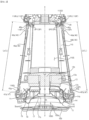
FIG. 2 , thelower body 110 may provide aninternal space 110S in which thefirst speaker 10 is installed. Thesecond speaker 20 may be installed in a space 110S2 of thelower body 110 which is provided independently of theinternal space 110S. Thelower body 110 may be referred to as ahousing 110 or anenclosure 110, and thefirst speaker 10 may be referred to as aspeaker 10 or aloudspeaker 10. Thespeaker 10 may include aframe 11, afirst plate 12a, apole piece 12b, asecond plate 12c, amagnet 13, abobbin 14, acoil 14a, aspider 16, adiaphragm 17, and anedge 18. - The
frame 11 may form the exterior of thespeaker 10. Theframe 11 may provide a space in which the components of thespeaker 10, which will be described below, are installed. Theframe 11 may be fixed to the inside of thehousing 110. - The
first plate 12a may form the upper side of thespeaker 10. Thepole piece 12b may protrude downward from a central portion of thefirst plate 12a, and may have a hollow cylinder shape or a solid cylinder shape. Thesecond plate 12c may be spaced downward from thefirst plate 12a and may have a ring shape. In this case, a portion of thepole piece 12b may pass through thesecond plate 12c, and an air gap (not numbered) may be formed between thepole piece 12b and thesecond plate 12c. - The
magnet 13 may be disposed between thefirst plate 12a and thesecond plate 12c and may have a ring shape. In this case, a portion of thepole piece 12b may pass through themagnet 13. Thebobbin 14 may be disposed in the air gap and may have a hollow cylinder shape that vertically extends. Thecoil 14a may be formed on or wound around an outer circumferential surface of thebobbin 14 and may be referred to as avoice coil 14a. For example, terminals and tinsel wire may transfer electric energy, output from an amplifier in thehousing 110, to thecoil 14a. - The
spider 16 may have elasticity. Thespider 16 may be disposed between thebobbin 14 and theframe 11, may be coupled to thebobbin 14 and theframe 11, and may support thebobbin 14. Thespider 16 may be referred to as adamper 16. - One side of the
diaphragm 17 may be coupled or attached to thebobbin 14, and another side of thediaphragm 17 may be supported by theedge 18 having elasticity. For example, thediaphragm 17 may have a cone or dome shape. Agasket 19 may be provided on a lateral surface of theedge 18, and may prevent interference of peripheral devices with respect to the vibratingdiaphragm 17. Adust cap 17a may cover the central portion of thediaphragm 17 and may prevent dust and the like from entering a magnetic circuit. - Accordingly, a magnetic line of force is formed in the air gap by the
magnet 13, and Lorentz force is generated when a current flows through thecoil 14a. The magnitude of Lorentz force is proportional to the magnitude of the magnetic line of force (magnetic flux density), the amount of electric current, and the length of the wound coil, and the direction of force may be perpendicular to the plane formed by the magnetic flux density and the current. That is, thediaphragm 17 may vibrate vertically. When thediaphragm 17 moves downward, positive (+) sound pressure is generated, and when thediaphragm 17 moves upward, negative (-) sound pressure is generated, thereby allowing thespeaker 10 to provide sound in a direction toward the lower side of thespeaker 10. - The air present in the
internal space 110S of thehousing 110 also resonates with the vibration of thediaphragm 17, such that the pressure thereof may be changed. In this case, apassive radiator 40 which will be described below may vibrate in response to a change in pressure of the air in theinternal space 110S, and may produce sound. - Meanwhile, a dome 100D may form a portion of the upper surface of the
base 100, and may be convex toward the central portion of thediaphragm 17 or thedust cap 17a. The dome 100D and thedust cap 17a may be vertically spaced apart from each other (see Ds ofFIG. 2 ). Accordingly, the sound from thespeaker 10 may be reflected horizontally by the dome 100D. - Referring to
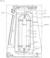
FIGS. 2 and3 , an opening OP may be formed through the lateral side of thehousing 110, and thepassive radiator 40 may be mounted to thehousing 110 and may block the opening OP. Thepassive radiator 40 may have a shape corresponding to the opening OP. Thepassive radiator 40 may be spaced apart from thespeaker 10 and may seal theinternal space 110S of thehousing 110 together with thespeaker 10. An upper end of thepassive radiator 40 may be adjacent to an upper end of thehousing 110, and a lower end of thepassive radiator 40 may be adjacent to a lower end of thehousing 110. An area of thepassive radiator 40 may be about twice an area of thediaphragm 17 of thespeaker 10. - The lateral surface of the
housing 110 may have acurved portion 110R and aflat portion 110P. Thepassive radiator 40 may be mounted on theflat portion 110P and may extend in a direction (see theta t ofFIG. 1 ) in which the lateral surface of thehousing 110 is inclined with respect to a vertical line. The aforementioned opening OP may be formed through theflat portion 110P. - For example, a plurality of
passive radiators 40 may be spaced apart from each other in a circumferential direction of thehousing 110. A sum of areas of the plurality ofpassive radiators 40 may be about twice the area of thediaphragm 17 of thespeaker 10. For example, a pair ofpassive radiators housing 110. For example, the pair ofradiators passive radiator 40a may be mounted on a first flat portion 110Pa and may block a first opening OP1 formed in the first flat portion 110Pa. A secondpassive radiator 40b may be mounted on a second flat portion 110Pb and may block a second opening OP2 formed in the second flat portion 110Pb. - Referring to
FIGS. 4 and5 , thepassive radiator 40 may be elongated. A length L of thepassive radiator 40 may be greater than a width W of thepassive radiator 40. For example, the length L may be about three times greater than the width W. For example, thepassive radiator 40 may have a generally elongated track shape. Thepassive radiator 40 may include adiaphragm 41 andedges edges dampers - The
diaphragm 41 may form the central portion of thepassive radiator 40. Thediaphragm 41 may be elongated. A length L0 of thediaphragm 41 may be about 7 times greater than a width W0 of thediaphragm 41. For example, thediaphragm 41 may have a shape corresponding to thepassive radiator 40. For example, thediaphragm 41 may have a generally elongated track shape. - The
edges edges diaphragm 41 to the outside of thediaphragm 41. Aflange 42 may be spaced apart from the diaphragm 41 (see Dr ofFIG. 4 ), and may form the circumference of thepassive radiator 40. In the width direction of thediaphragm 41, theflange 42 may be disposed parallel to thediaphragm 41. Agroove 43 is formed by being recessed from one surface (outer surface) of thepassive radiator 40 toward another surface (inner surface) thereof (see g ofFIG. 4 ) and may extend along the circumference of thediaphragm 41. Thegroove 43 may be formed between thediaphragm 41 and theflange 42 and may connect thediaphragm 41 and theflange 42. - A
rib 44 may be adjacent to a distal end of theflange 42, may protrude from the rear of theflange 42, and may extend in a circumferential direction of theflange 42. Aninsertion groove 40g may be formed between therib 44 and thegroove 43. Theinsertion groove 40g may be locked by a protrusion 110Pt (seeFIG. 2 ) of theflat portion 110P, and therib 44 may be coupled or attached to theflat portion 110P. Accordingly, thepassive radiator 40 may be mounted to theflat portion 110P. - In this case, the
diaphragm 41 and thegroove 43 of thepassive radiator 40 may pass through the opening OP and may be directed toward theinternal space 110S of the housing 110 (seeFIG. 2 ). - Meanwhile, gates 40h1 and 40h2 (see
FIG. 5 ) may or may not be formed on the rear surface of thediaphragm 41. - Referring to
FIGS. 6 and7 , thediaphragm 41 may include acore 410 and acover 411. Thecore 410 may have a shape corresponding to the overall shape of thediaphragm 41. Thecover 411 may be thin and may cover thecore 410. For example, thecore 410 may be a metal plate of zinc alloy or other material. For example, thecover 411 may include rubber, silicone or resin material. For example, theedges cover 411. For example, thecover 411 may be formed as one body with theedges - Referring to
FIG. 8 , thepassive radiator 40 may include astraight section 40A, a firstcurved section 40B, and a secondcurved section 40C in a longitudinal direction of thepassive radiator 40. A length of thestraight section 40A may be greater than the sum of a length of the firstcurved section 40B and a length of the secondcurved section 40C. A width of thestraight section 40A, a width of the firstcurved section 40B, and a width of the secondcurved section 40C may be equal to each other. - The
straight section 40A may extend straight in the longitudinal direction of thepassive radiator 40. In thestraight section 40A, thediaphragm 41 may have a long square bar shape in the longitudinal direction of thepassive radiator 40. In thestraight section 40A, theflange 42 may have a long band shape in the longitudinal direction of thepassive radiator 40. In thestraight section 40A, thegroove 43 may have a long semicylindrical shape in the longitudinal direction of thepassive radiator 40. - The first
curved section 40B may be connected to one end of thestraight section 40A. The firstcurved section 40B may extend in a rounded manner. In the firstcurved section 40B, thediaphragm 41 may have a semicircular shape that is convex in a direction opposite to thestraight section 40A. In the firstcurved section 40B, theflange 42 may have an upwardly convex band shape. In the firstcurved section 40B, thegroove 43 may have an inverted U-shape that extends along thediaphragm 41 and theflange 42. - A center of
curvature 01 of the firstcurved section 40B may be located at the center of a boundary Bo1 between thestraight section 40A and the firstcurved section 40B. The center ofcurvature 01 may be referred to as a first center ofcurvature 01, and the boundary Bo1 may be referred to as a first boundary Bo1. In the firstcurved section 40B, a difference between a radius R1b of an inner circumferential surface of theflange 42 and a radius R1a of thediaphragm 41 may be equal to the width Dr of thegroove 43. - The second
curved section 40C may be connected to another end of thestraight section 40A. The secondcurved section 40C may extend in a rounded manner. In the secondcurved section 40C, thediaphragm 41 may have a semicircular shape that is convex in a direction opposite to thestraight section 40A. In the secondcurved section 40C, theflange 42 may have a downwardly convex band shape. In the secondcurved section 40C, thegroove 43 may have a U-shape that extends along thediaphragm 41 and theflange 42. - A center of
curvature 02 of the secondcurved section 40C may be located at the center of a boundary Bo2 between thestraight section 40A and the secondcurved section 40C. The center ofcurvature 02 may be referred to as a second center ofcurvature 02, and the boundary Bo2 may be referred to as a second boundary Bo2. In the secondcurved section 40C, a difference between a radius R2b of an inner circumferential surface of theflange 42 and a radius R2a of thediaphragm 41 may be equal to the width Dr of thegroove 43. - A vertical axis VL may pass through the center of the
passive radiator 40 to extend in the length direction of thepassive radiator 40. Thepassive radiator 40 may be laterally symmetric about the vertical axis VL. A horizontal axis HL may pass through the center of thepassive radiator 40 to extend in the width direction of thepassive radiator 40. Thepassive radiator 40 may be vertically symmetric about the horizontal axis HL. That is, the firstcurved section 40B and the secondcurved section 40C may be vertically symmetric about the horizontal axis HL. - Referring back to
FIGS. 6 and8 , anupper supporter 46 may be adjacent to the upper end of thediaphragm 41 and may protrude from one surface of thepassive radiator 40 in the thickness direction of thepassive radiator 40. Theupper supporter 46 may be made of the same material as that of thepassive radiator 40 and may be formed as one body with thepassive radiator 40. Theupper supporter 46 may be positioned or aligned radially with respect to the first center ofcurvature 01. Theupper supporter 46 may be formed on thediaphragm 41, theflange 42, and thegroove 43. Theupper supporter 46 may be referred to as anupper weight 46. Theupper supporter 46 may include afirst part 461, asecond part 462, and athird part 463. A length Lr of theupper supporter 46 may be 21. 5 mm. - The
first part 461 may protrude from one surface of thediaphragm 41 in the thickness direction of thediaphragm 41. Thesecond part 462 may protrude from one surface of theflange 42 in the thickness direction of theflange 42. Thethird part 463 may protrude from one surface of thegroove 43 in the thickness direction of thegroove 43. Thefirst part 461 and thesecond part 462 may have a flat block shape. Thethird part 463 may have a curved shape along thegroove 43, and may connect thefirst part 461 and thesecond part 462. Thefirst part 461, thesecond part 462, and thethird part 463 may be substantially in the shape of the Greek letter omega. - The
first part 461, thesecond part 462, and thethird part 463 may be formed as one body. Thefirst part 461, thesecond part 462, and thethird part 463 may be formed as one body with thediaphragm 41, theflange 42, and thegroove 43, respectively. - Further, a thickness Tr1 of the
first part 461, a thickness Tr2 of thesecond part 462, and a thickness Tr3 of thethird part 463 may be equal to or different from each other. For example, the thicknesses Tr1, Tr2, and Tr3 may be 1 mm. For example, the thickness Tr1 of thefirst part 461 may be a minimum thickness of theupper supporter 46. For example, a distance Ds between thefirst part 461 and thesecond part 462 may be equal to a value obtained by subtracting twice the thickness Tr3 of thethird part 463 from the width Dr of thegroove 43. - In addition, the width of the
first part 461, the width of thesecond part 462, and the width of thethird part 463 may be equal to (see Wr ofFIG. 8 ) or different from each other. For example, the width Wr may range from 4 mm to 10 mm. For example, the width Wr may be 5 mm. - For example, a plurality of
upper supporters 46 may be spaced apart from each other in a circumferential direction of the firstcurved section 40B. For example, an angle between the plurality ofupper supporters 46 may be constant in the circumferential direction of the firstcurved section 40B. For example, an angle between the threeupper supporters curved section 40B. - A first
upper supporter 46a may be located on the vertical axis VL and may be disposed parallel to the vertical axis VL. The firstupper supporter 46a may be referred to as acenter supporter 46a. - A second
upper supporter 46b may be adjacent to the first boundary Bo1 may be disposed in a direction intersecting the longitudinal direction of thediaphragm 41. The secondupper supporter 46b may be located below the first boundary Bo1 and may be disposed parallel to the first boundary Bo1. In this case, the firstupper supporter 46a may be spaced 90 degrees apart from the secondupper supporter 46b in a clockwise direction with respect to the first center ofcurvature 01. Alternatively, the secondupper supporter 46b may be disposed between the first boundary Bo1 and one side of the firstupper supporter 46a and may be disposed radially with respect to the first center ofcurvature 01. - A third
upper supporter 46c may be adjacent to the first boundary Bo1 may be disposed in a direction intersecting the longitudinal direction of thediaphragm 41. The thirdupper supporter 46c may be located below the first boundary Bo1 and may be disposed parallel to the first boundary Bo1. In this case, the firstupper supporter 46a may be spaced 90 degrees apart from the thirdupper supporter 46b in a counterclockwise direction with respect to the first center ofcurvature 01. Alternatively, the thirdupper supporter 46c may be disposed between the first boundary Bo1 and another side of the firstupper supporter 46a and may be disposed radially with respect to the first center ofcurvature 01. - Referring back to
FIGS. 7 and8 , alower supporter 47 may be adjacent to the lower end of thediaphragm 41 and may protrude from one surface of thepassive radiator 40 in the thickness direction of thepassive radiator 40. Thelower supporter 47 may be made of the same material as that of thepassive radiator 40 and may be formed as one body with thepassive radiator 40. Theupper supporter 47 may be positioned or aligned radially with respect to the second center ofcurvature 02. Thelower supporter 47 may be formed on thediaphragm 41, theflange 42, and thegroove 43. Thelower supporter 47 may be referred to as alower weight 47. Thelower supporter 47 may include afirst part 471, asecond part 472, and athird part 473. A length Lr of thelower supporter 47 may be 21. 5 mm. - The
first part 471 may protrude from one surface of thediaphragm 41 in the thickness direction of thediaphragm 41. Thesecond part 472 may protrude from one surface of theflange 42 in the thickness direction of theflange 42. Thethird part 473 may protrude from one surface of thegroove 43 in the thickness direction of thegroove 43. Thefirst part 471 and thesecond part 472 may have a flat block shape. Thethird part 473 may have a curved shape along thegroove 43, and may connect thefirst part 471 and thesecond part 472. Thefirst part 471, thesecond part 472, and thethird part 473 may be substantially in the shape of the Greek letter omega. - The
first part 471, thesecond part 472, and thethird part 473 may be formed as one body. Thefirst part 471, thesecond part 472, and thethird part 473 may be formed as one body with thediaphragm 41, theflange 42, and thegroove 43, respectively. - Further, a thickness Tr4 of the
first part 471, a thickness Tr5 of thesecond part 472, and a thickness Tr6 of thethird part 473 may be equal to or different from each other. For example, the thickness Tr4 of thefirst part 471 may be a minimum thickness of thelower supporter 47. For example, a distance Dt between thefirst part 471 and thesecond part 472 may be equal to a value obtained by subtracting twice the thickness Tr6 of thethird part 473 from the width Dr of thegroove 43. - In addition, the width of the
first part 471, the width of thesecond part 472, and the width of thethird part 473 may be equal to (see Wr ofFIG. 8 ) or different from each other. For example, the width Wr may range from 4 mm to 10 mm. For example, the width Wr may be 5 mm. - For example, a plurality of
lower supporters 47 may be spaced apart from each other in a circumferential direction of the secondcurved section 40C. For example, an angle between the plurality oflower supporters 47 may be constant in the circumferential direction of the secondcurved section 40C. For example, an angle between the threelower supporters curved section 40C. - A first
lower supporter 47a may be located on the vertical axis VL and may be disposed parallel to the vertical axis VL. The firstlower supporter 47a may be referred to as acenter supporter 46a. - A second
lower supporter 47b may be adjacent to the second boundary Bo2 may be disposed in a direction intersecting the longitudinal direction of thediaphragm 41. The secondlower supporter 47b may be located below the second boundary Bo2 and may be disposed parallel to the second boundary Bo2. In this case, the firstlower supporter 47a may be spaced 90 degrees apart from the secondlower supporter 47b in a counterclockwise direction with respect to the second center ofcurvature 02. Alternatively, the secondlower supporter 47b may be disposed between the second boundary Bo2 and one side of the firstlower supporter 47a and may be disposed radially with respect to the second center ofcurvature 02. - A third
lower supporter 47c may be adjacent to the second boundary Bo2 and may be disposed in a direction intersecting the longitudinal direction of thediaphragm 41. The thirdlower supporter 47c may be located below the second boundary Bo2 and may be disposed parallel to the second boundary Bo2. In this case, the firstlower supporter 47a may be spaced 90 degrees apart from the thirdlower supporter 47c in a clockwise direction with respect to the second center ofcurvature 02. Alternatively, the thirdlower supporter 47c may be disposed between the second boundary Bo2 and another side of the firstlower supporter 47a and may be disposed radially with respect to the second center ofcurvature 02. - Referring to
FIGS. 9 to 13 , theupper supporter 46 may be disposed at or adjacent to the upper end of thepassive radiator 40, and thelower supporter 47 may be disposed at or adjacent to the lower end of thepassive radiator 40. As described above, thesupporters passive radiator 40 or at portions adjacent thereto, and may not be provided at other portions of thepassive radiator 40. That is, thepassive radiator 40 does not include a supporter between theupper supporter 46 and thelower supporter 47. In other words, thepassive radiator 40 may have a constant cross-section between theupper supporter 46 and thelower supporter 47. - In addition, the
upper supporter 46 and thelower supporter 47 may be vertically symmetrical. That is, the description of theupper supporter 46 may be symmetrically applied to thelower supporter 47. - Referring to
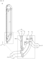
FIG. 9 , for example, thefirst part 461 of the firstupper supporter 46a may be disposed on one surface of thediaphragm 41, and thesecond part 462 of the firstupper supporter 46a that is opposite to thefirst part 461 may be disposed on one surface of theflange 42. Thefirst part 461 may be spaced a first distance Da apart from the first center ofcurvature 01 in a direction from thefirst part 461 toward thesecond part 462. - In addition, the second
upper supporter 46b and the thirdupper supporter 47c may be spaced apart from each other in the longitudinal direction of the first boundary Bo1, and the first center ofcurvature 01 may be located between the secondupper supporter 46b and the thirdupper supporter 47c. - Specifically, the
first part 461 of the secondupper supporter 46b may be disposed on one surface of thediaphragm 41, and thesecond part 462 of the secondupper supporter 46b that is opposite to thefirst part 461 may be disposed on one surface of theflange 42. Thefirst part 461 may be spaced a second distance Db apart from the first center ofcurvature 01 in a direction from thefirst part 461 toward thesecond part 462. - Specifically, the
first part 461 of the thirdupper supporter 46c may be disposed on one surface of thediaphragm 41, and thesecond part 462 of the thirdupper supporter 46c that is opposite to thefirst part 461 may be disposed on one surface of theflange 42. Thefirst part 461 may be spaced a third distance Dc apart from the first center ofcurvature 01 in a direction from thefirst part 461 toward thesecond part 462. - For example, the first distance Da, the second distance Db, and the third distance Dc may be substantially equal to or different from each other.
- Accordingly, the
upper supporter 46 and thelower supporter 47 may minimize rolling of thepassive radiator 40 that vibrates in response to the operation of the speaker 10 (seeFIG. 2 ). Here, the rolling may refer to a rotational motion about the vertical axis VL (seeFIG. 8 ) of thepassive radiator 40. In addition, theupper supporter 46 and thelower supporter 47 may minimize pitching of thepassive radiator 40 that vibrates in response to the operation of thespeaker 10. Here, the pitching may refer to a rotational motion about the horizontal axis HL (seeFIG. 8 ) of thepassive radiator 40. That is, thepassive radiator 40 including thesupporters passive radiator 40 ofFIG. 2 ) in response to the operation of the speaker 10 (seeFIG. 2 ), and may have excellent low-frequency sound reproduction characteristics. - Referring to
FIG. 10 , for example, a first part 461' of the firstupper supporter 46a may be adjacent to or disposed on the first boundary Bo1 (see the solid line ofFIG. 10 ). Alternatively, a portion of the first part 461' of the firstupper supporter 46a may be located below the first boundary Bo1 and may be disposed between the secondupper supporter 46b and the thirdupper supporter 46c (see the dotted line ofFIG. 10 ). In this case, thefirst part 461 of the secondupper supporter 46b and thefirst part 461 of the thirdupper supporter 46c may be opposite each other with respect to the portion of first part 461', and may be spaced apart from the portion of the first part 461'. - Accordingly, the
upper supporter 46 and thelower supporter 47 may minimize rolling of thepassive radiator 40 that vibrates in response to the operation of the speaker 10 (seeFIG. 2 ). Here, the rolling may refer to a rotational motion about the vertical axis VL (seeFIG. 8 ) of thepassive radiator 40. In addition, theupper supporter 46 and thelower supporter 47 may minimize pitching of thepassive radiator 40 that vibrates in response to the operation of thespeaker 10. Here, the pitching may refer to a rotational motion about the horizontal axis HL (seeFIG. 8 ) of thepassive radiator 40. That is, thepassive radiator 40 including thesupporters passive radiator 40 ofFIG. 2 ) in response to the operation of the speaker 10 (seeFIG. 2 ), and may have excellent low-frequency sound reproduction characteristics. - Referring to
FIG. 11 , for example, a distal end of afirst part 461" of the secondupper supporter 46b may be located at the first center ofcurvature 01, and a distal end of afirst part 461" of the thirdupper supporter 46c may be located at the first center ofcurvature 01. That is, thefirst part 461" of the secondupper supporter 46b may contact, or may be formed as one body with, thefirst part 461" of the thirdupper supporter 46c. In this case, thefirst part 461 of the firstupper supporter 46a may be spaced apart from thefirst part 461". - Accordingly, the
upper supporter 46 and thelower supporter 47 may minimize rolling of thepassive radiator 40 that vibrates in response to the operation of the speaker 10 (seeFIG. 2 ). Here, the rolling may refer to a rotational motion about the vertical axis VL (seeFIG. 8 ) of thepassive radiator 40. In addition, theupper supporter 46 and thelower supporter 47 may minimize pitching of thepassive radiator 40 that vibrates in response to the operation of thespeaker 10. Here, the pitching may refer to a rotational motion about the horizontal axis HL (seeFIG. 8 ) of thepassive radiator 40. That is, thepassive radiator 40 including thesupporters passive radiator 40 ofFIG. 2 ) in response to the operation of the speaker 10 (seeFIG. 2 ), and may have excellent low-frequency sound reproduction characteristics. - Referring to
FIG. 12 , for example, a distal end of afirst part 461" of the secondupper supporter 46b may be located at the first center ofcurvature 01, and a distal end of afirst part 461" of the thirdupper supporter 46c may be located at the first center ofcurvature 01. That is, thefirst part 461" of the secondupper supporter 46b may contact, or may be formed as one body with, thefirst part 461" of the thirdupper supporter 46c. In this case, afirst part 461‴ of the firstupper supporter 46a may be located on the first boundary Bo1. That is, thefirst part 461‴ of the firstupper supporter 46a may contact, or may be formed as one body with, thefirst part 461". - Accordingly, the
upper supporter 46 and thelower supporter 47 may minimize rolling of thepassive radiator 40 that vibrates in response to the operation of the speaker 10 (seeFIG. 2 ). Here, the rolling may refer to a rotational motion about the vertical axis VL (seeFIG. 8 ) of thepassive radiator 40. In addition, theupper supporter 46 and thelower supporter 47 may minimize pitching of thepassive radiator 40 that vibrates in response to the operation of thespeaker 10. Here, the pitching may refer to a rotational motion about the horizontal axis HL (seeFIG. 8 ) of thepassive radiator 40. That is, thepassive radiator 40 including thesupporters passive radiator 40 ofFIG. 2 ) in response to the operation of the speaker 10 (seeFIG. 2 ), and may have excellent low-frequency sound reproduction characteristics. - Referring to
FIG. 13 , for example, bridges 464 and 465 may connect the firstupper supporter 46a, the secondupper supporter 46b, and the thirdupper supporter 46c. Afirst bridge 464 may connect thefirst part 461 of the firstupper supporter 46a and thefirst part 461 of the secondupper supporter 46b, and may have a curved shape along thegroove 43. Asecond bridge 465 may connect thefirst part 461 of the firstupper supporter 46a and thefirst part 461 of the thirdupper supporter 46c, and may have a curved shape along thegroove 43. Thebridges upper supporter 46a, the secondupper supporter 46b, and the thirdupper supporter 46c. - Accordingly, the
upper supporter 46 and thelower supporter 47 may minimize rolling of thepassive radiator 40 that vibrates in response to the operation of the speaker 10 (seeFIG. 2 ). Here, the rolling may refer to a rotational motion about the vertical axis VL (seeFIG. 8 ) of thepassive radiator 40. In addition, theupper supporter 46 and thelower supporter 47 may minimize pitching of thepassive radiator 40 that vibrates in response to the operation of thespeaker 10. Here, the pitching may refer to a rotational motion about the horizontal axis HL (seeFIG. 8 ) of thepassive radiator 40. That is, thepassive radiator 40 including thesupporters passive radiator 40 ofFIG. 2 ) in response to the operation of the speaker 10 (seeFIG. 2 ), and may have excellent low-frequency sound reproduction characteristics. - Referring to
FIGS. 1 to 13 , a sound device according to an embodiment of the present disclosure may include: a housing having an internal space; a speaker mounted at the housing; and a passive radiator spaced apart from the speaker and mounted at the housing, wherein the passive radiator may include: a diaphragm extending long, the diaphragm having a first end and a second end opposite each other in a longitudinal direction of the diaphragm; an edge extending along a perimeter of the diaphragm and coupled to the diaphragm and the housing; an upper supporter adjacent to the first end and protruding from the diaphragm and the edge; and a lower supporter adjacent to the second end and protruding from the diaphragm and the edge. - The speaker may be mounted at an upper surface or a lower surface of the housing, and the passive radiator may be mounted at a side surface of the housing, and the speaker and the passive radiator may define a portion of a boundary of the internal space of the housing.
- A horizontal axis may pass through a center of the diaphragm and may extend in a width direction of the diaphragm, wherein the upper supporter may be symmetric to the lower supporter with respect to the horizontal axis.
- The upper supporter may include a plurality of upper supporters disposed along in a perimeter direction of the diaphragm.
- A portion of each of the plurality of upper supporters may be located on the diaphragm, and may be spaced apart from each other.
- A portion of each of the plurality of upper supporters may be located on the diaphragm, and may be connected to each other at least two by two.
- The plurality of upper supporters may include: a first upper supporter located at a longitudinal axis of the diaphragm and disposed parallel to the longitudinal axis; a second upper supporter which, in the perimeter direction of the diaphragm, is spaced apart from the first upper supporter in a first direction; and a third upper supporter which, in the perimeter direction of the diaphragm, is spaced apart from the first upper supporter in a second direction opposite the first direction.
- The passive radiator may include: a straight section extending in a longitudinal direction of the diaphragm; and a first curved section connected to the straight section and including a portion of the diaphragm that defines the first end, wherein the second upper supporter and the third upper supporter may be adjacent to a first boundary which is a boundary between the straight section and the first curved section.
- The second upper supporter and the third upper supporter may be located below the first boundary and may belong to the straight section.
- The edge may include: a flange spaced apart from the diaphragm and fixed to the housing; and a groove located between the diaphragm and the flange and connecting the diaphragm and the flange, wherein in the first curved section, the diaphragm may have a semicircular shape that is convex in a direction opposite the straight section, and the flange and the groove may have a curved shape along the circumference of the diaphragm in the first curved section.
- Each of the plurality of upper supporters may include: a first part protruding from one surface of the diaphragm in a thickness direction of the diaphragm; a second part protruding from one surface of the flange in a thickness direction of the flange; and a third part protruding from one surface of the groove in a thickness direction of the groove, wherein the first part, the second part, and the third part may be formed as one body.
- The diaphragm may include: a core including a metal material; and a cover covering the core, wherein the cover, the edge, the upper supporter, and the lower supporter may be formed as one body.
- The passive radiator may have a constant cross-section between the upper supporter and the lower supporter.
- Certain embodiments or other embodiments of the disclosure described above are not mutually exclusive or distinct from each other. Any or all elements of the embodiments of the disclosure described above may be combined or combined with each other in configuration or function.
- For example, a configuration "A" described in one embodiment of the disclosure and the drawings and a configuration "B" described in another embodiment of the disclosure and the drawings may be combined with each other. Namely, although the combination between the configurations is not directly described, the combination is possible except in the case where it is described that the combination is impossible.
- The foregoing embodiments are merely examples and are not to be considered as limiting the present disclosure. The scope of the present disclosure should be determined by rational interpretation of the appended claims, and all modifications within the equivalents of the disclosure are intended to be included within the scope of the present disclosure.
Claims (11)
- A sound device comprising:a housing having an internal space;a speaker mounted at the housing; anda passive radiator spaced apart from the speaker and mounted at the housing,wherein the passive radiator comprises:a diaphragm extending long, the diaphragm having a first end and a second end opposite each other in a longitudinal direction of the diaphragm;an edge extending along a perimeter of the diaphragm and coupled to the diaphragm and the housing;an upper supporter adjacent to the first end and protruding from the diaphragm and the edge; anda lower supporter adjacent to the second end and protruding from the diaphragm and the edge.
- The sound device of claim 1, wherein the speaker is mounted at an upper surface or a lower surface of the housing,wherein the passive radiator is mounted at a side surface of the housing,wherein the speaker and the passive radiator define a portion of a boundary of the internal space of the housing.
- The sound device of claim 1, wherein a horizontal axis passes through a center of the diaphragm and extends in a width direction of the diaphragm,
wherein the upper supporter is symmetric to the lower supporter with respect to the horizontal axis. - The sound device of claim 1, wherein the upper supporter comprises a plurality of upper supporters disposed along a perimeter direction of the diaphragm.
- The sound device of claim 4, wherein a portion of each of the plurality of upper supporters is located on the diaphragm, and are spaced apart from each other.
- The sound device of claim 4, wherein a portion of each of the plurality of upper supporters is located on the diaphragm, and are connected to each other at least two by two.
- The sound device of claim 4, wherein the plurality of upper supporters comprise:a first upper supporter located at a longitudinal axis of the diaphragm and disposed parallel to the longitudinal axis;a second upper supporter which, in the perimeter direction of the diaphragm, is spaced apart from the first upper supporter in a first direction; anda third upper supporter which, in the perimeter direction of the diaphragm, is spaced apart from the first upper supporter in a second direction opposite the first direction.
- The sound device of claim 7, wherein the passive radiator comprises:a straight section extending in a longitudinal direction of the diaphragm; anda first curved section connected to the straight section and including a portion of the diaphragm that defines the first end,wherein the second upper supporter and the third upper supporter are adjacent to a first boundary which is a boundary between the straight section and the first curved section.
- The sound device of claim 8, wherein the second upper supporter and the third upper supporter are located below the first boundary and belong to the straight section.
- The sound device of claim 8, wherein the edge comprises:a flange spaced apart from the diaphragm and fixed to the housing; anda groove located between the diaphragm and the flange and connecting the diaphragm and the flange,wherein, in the first curved section, the diaphragm has a semicircular shape that is convex in a direction opposite the straight section,wherein, in the first curved section, the flange and the groove have a curved shape along the perimeter of the diaphragm.
- The sound device of claim 10, wherein each of the plurality of upper supporters comprises:a first part protruding from one surface of the diaphragm in a thickness direction of the diaphragm;a second part protruding from one surface of the flange in a thickness direction of the flange; anda third part protruding from one surface of the groove in a thickness direction of the groove,wherein the first part, the second part, and the third part are formed as one body.
Applications Claiming Priority (2)
| Application Number | Priority Date | Filing Date | Title |
|---|---|---|---|
| KR1020220072998A KR102546987B1 (en) | 2022-06-15 | 2022-06-15 | Sound device |
| PCT/KR2023/000765 WO2023243797A1 (en) | 2022-06-15 | 2023-01-17 | Sound device |
Publications (2)
| Publication Number | Publication Date |
|---|---|
| EP4539495A1 true EP4539495A1 (en) | 2025-04-16 |
| EP4539495A4 EP4539495A4 (en) | 2025-10-15 |
Family
ID=86988853
Family Applications (1)
| Application Number | Title | Priority Date | Filing Date |
|---|---|---|---|
| EP23824027.9A Pending EP4539495A4 (en) | 2022-06-15 | 2023-01-17 | ACOUSTIC DEVICE |
Country Status (3)
| Country | Link |
|---|---|
| EP (1) | EP4539495A4 (en) |
| KR (1) | KR102546987B1 (en) |
| WO (1) | WO2023243797A1 (en) |
Family Cites Families (9)
| Publication number | Priority date | Publication date | Assignee | Title |
|---|---|---|---|---|
| JPS5441710B2 (en) * | 1973-03-16 | 1979-12-10 | ||
| JPH06315194A (en) * | 1993-04-28 | 1994-11-08 | Matsushita Electric Ind Co Ltd | Speaker |
| US7568552B2 (en) * | 2004-01-15 | 2009-08-04 | Bose Corporation | Acoustic passive radiator rocking mode reducing |
| CN103648071B (en) * | 2007-11-20 | 2018-11-02 | 松下知识产权经营株式会社 | Loud speaker, video equipment and portable information processing device |
| KR100937335B1 (en) * | 2009-08-27 | 2010-01-18 | 주식회사 벨포원 | Micro speaker and method for fabricating the same |
| JP2014192563A (en) * | 2013-03-26 | 2014-10-06 | Mitsubishi Electric Corp | Speaker device |
| WO2018022087A1 (en) * | 2016-07-28 | 2018-02-01 | Bose Corporation | Acoustic deflector for omni-directional speaker system |
| KR101975973B1 (en) * | 2018-02-02 | 2019-05-08 | (주)인포마크 | Omni-directional Speaker Having Side-Mounting Type Passive Radiator |
| CN113852891B (en) * | 2021-10-19 | 2025-01-21 | 歌尔科技有限公司 | Passive radiators and sound-generating devices |
-
2022
- 2022-06-15 KR KR1020220072998A patent/KR102546987B1/en active Active
-
2023
- 2023-01-17 EP EP23824027.9A patent/EP4539495A4/en active Pending
- 2023-01-17 WO PCT/KR2023/000765 patent/WO2023243797A1/en not_active Ceased
Also Published As
| Publication number | Publication date |
|---|---|
| WO2023243797A1 (en) | 2023-12-21 |
| EP4539495A4 (en) | 2025-10-15 |
| KR102546987B1 (en) | 2023-06-22 |
Similar Documents
| Publication | Publication Date | Title |
|---|---|---|
| TWI406575B (en) | Micro-speaker | |
| US8699745B2 (en) | Speaker, and mobile electronic device | |
| US9185491B2 (en) | Reinforced diaphragm for a low profile loudspeaker transducer with two sets of inner and outer magnets | |
| US8879774B2 (en) | Loudspeaker magnet assembly with two inner magnets comprising a central bore | |
| JP5258907B2 (en) | Nested compound loudspeaker drive unit | |
| JP6515392B2 (en) | Voice vibration generator | |
| US8548191B2 (en) | Loudspeaker magnet having a channel | |
| JPH11262089A (en) | Speaker device | |
| WO2022166388A1 (en) | Sound producing device and earphone | |
| JP2019041271A (en) | Frame, speaker unit employing the same, headphone, and earphone | |
| US9137607B2 (en) | Low profile loudspeaker suspension system | |
| US20150195629A1 (en) | Passive radiator | |
| EP4539495A1 (en) | Sound device | |
| KR20080095962A (en) | Electroacoustic conversion unit having the output structure of the same phase bass reversal system with distortion prevention performance | |
| JP4385981B2 (en) | Electrodynamic speaker | |
| JP2012109851A (en) | Speaker | |
| KR102667294B1 (en) | 2way speaker comprising tweeter spekaer having fpcm as diaphragm | |
| CN119545259A (en) | Speakers and electronic devices | |
| JP4445182B2 (en) | Speaker device | |
| CN208143457U (en) | Moving-coil structure and earphone | |
| JP2003324793A (en) | Speaker apparatus and diaphragm | |
| JPS6019419Y2 (en) | composite speaker | |
| KR101775427B1 (en) | Speaker Unit | |
| US12413896B2 (en) | Two-way speaker | |
| KR20260026136A (en) | High-pitched speaker for earphones |
Legal Events
| Date | Code | Title | Description |
|---|---|---|---|
| STAA | Information on the status of an ep patent application or granted ep patent |
Free format text: STATUS: THE INTERNATIONAL PUBLICATION HAS BEEN MADE |
|
| PUAI | Public reference made under article 153(3) epc to a published international application that has entered the european phase |
Free format text: ORIGINAL CODE: 0009012 |
|
| STAA | Information on the status of an ep patent application or granted ep patent |
Free format text: STATUS: REQUEST FOR EXAMINATION WAS MADE |
|
| 17P | Request for examination filed |
Effective date: 20250109 |
|
| AK | Designated contracting states |
Kind code of ref document: A1 Designated state(s): AL AT BE BG CH CY CZ DE DK EE ES FI FR GB GR HR HU IE IS IT LI LT LU LV MC ME MK MT NL NO PL PT RO RS SE SI SK SM TR |
|
| DAV | Request for validation of the european patent (deleted) | ||
| DAX | Request for extension of the european patent (deleted) | ||
| A4 | Supplementary search report drawn up and despatched |
Effective date: 20250911 |
|
| RIC1 | Information provided on ipc code assigned before grant |
Ipc: H04R 1/02 20060101AFI20250905BHEP Ipc: H04R 9/06 20060101ALI20250905BHEP Ipc: H04R 9/02 20060101ALI20250905BHEP Ipc: H04R 7/20 20060101ALI20250905BHEP Ipc: H04R 1/28 20060101ALI20250905BHEP Ipc: H04R 1/34 20060101ALI20250905BHEP |