EP4539494A1 - Loudspeaker cover plate, sound playing device and terminal - Google Patents
Loudspeaker cover plate, sound playing device and terminal Download PDFInfo
- Publication number
- EP4539494A1 EP4539494A1 EP23822893.6A EP23822893A EP4539494A1 EP 4539494 A1 EP4539494 A1 EP 4539494A1 EP 23822893 A EP23822893 A EP 23822893A EP 4539494 A1 EP4539494 A1 EP 4539494A1
- Authority
- EP
- European Patent Office
- Prior art keywords
- cover plate
- loudspeaker
- holes
- loudspeaker cover
- substrate
- Prior art date
- Legal status (The legal status is an assumption and is not a legal conclusion. Google has not performed a legal analysis and makes no representation as to the accuracy of the status listed.)
- Pending
Links
Images


Classifications
-
- H—ELECTRICITY
- H04—ELECTRIC COMMUNICATION TECHNIQUE
- H04R—LOUDSPEAKERS, MICROPHONES, GRAMOPHONE PICK-UPS OR LIKE ACOUSTIC ELECTROMECHANICAL TRANSDUCERS; ELECTRIC HEARING AIDS; PUBLIC ADDRESS SYSTEMS
- H04R1/00—Details of transducers, loudspeakers or microphones
- H04R1/02—Casings; Cabinets ; Supports therefor; Mountings therein
-
- H—ELECTRICITY
- H04—ELECTRIC COMMUNICATION TECHNIQUE
- H04R—LOUDSPEAKERS, MICROPHONES, GRAMOPHONE PICK-UPS OR LIKE ACOUSTIC ELECTROMECHANICAL TRANSDUCERS; ELECTRIC HEARING AIDS; PUBLIC ADDRESS SYSTEMS
- H04R1/00—Details of transducers, loudspeakers or microphones
- H04R1/02—Casings; Cabinets ; Supports therefor; Mountings therein
- H04R1/023—Screens for loudspeakers
-
- H—ELECTRICITY
- H04—ELECTRIC COMMUNICATION TECHNIQUE
- H04R—LOUDSPEAKERS, MICROPHONES, GRAMOPHONE PICK-UPS OR LIKE ACOUSTIC ELECTROMECHANICAL TRANSDUCERS; ELECTRIC HEARING AIDS; PUBLIC ADDRESS SYSTEMS
- H04R31/00—Apparatus or processes specially adapted for the manufacture of transducers or diaphragms therefor
-
- H—ELECTRICITY
- H04—ELECTRIC COMMUNICATION TECHNIQUE
- H04R—LOUDSPEAKERS, MICROPHONES, GRAMOPHONE PICK-UPS OR LIKE ACOUSTIC ELECTROMECHANICAL TRANSDUCERS; ELECTRIC HEARING AIDS; PUBLIC ADDRESS SYSTEMS
- H04R9/00—Transducers of moving-coil, moving-strip, or moving-wire type
- H04R9/02—Details
-
- H—ELECTRICITY
- H04—ELECTRIC COMMUNICATION TECHNIQUE
- H04R—LOUDSPEAKERS, MICROPHONES, GRAMOPHONE PICK-UPS OR LIKE ACOUSTIC ELECTROMECHANICAL TRANSDUCERS; ELECTRIC HEARING AIDS; PUBLIC ADDRESS SYSTEMS
- H04R9/00—Transducers of moving-coil, moving-strip, or moving-wire type
- H04R9/06—Loudspeakers
-
- H—ELECTRICITY
- H04—ELECTRIC COMMUNICATION TECHNIQUE
- H04R—LOUDSPEAKERS, MICROPHONES, GRAMOPHONE PICK-UPS OR LIKE ACOUSTIC ELECTROMECHANICAL TRANSDUCERS; ELECTRIC HEARING AIDS; PUBLIC ADDRESS SYSTEMS
- H04R2499/00—Aspects covered by H04R or H04S not otherwise provided for in their subgroups
- H04R2499/10—General applications
- H04R2499/13—Acoustic transducers and sound field adaptation in vehicles
Definitions
- the present invention relates to the technical field of loudspeakers, in particular to a loudspeaker cover plate, a sound playing apparatus and a terminal.
- Sound box refers to a sound playing apparatus that may convert audio signals into sound. It may amplify the audio signals and then play back the sound from the sound box itself to make the sound louder. Sound box is the terminal of the whole sound system, and its function is to convert audio electric energy into corresponding sound energy and radiate which into space. Sound box is an extremely important part of sound system, which is responsible for converting electrical signals into acoustic signals for people's ears to listen to directly. Sound box has a very wide range of applications, such as radios, players, notebooks, vehicles and other devices with sound generation functions.
- sound boxes typically include a loudspeaker and a loudspeaker cover plate covered on top of the loudspeaker, where the loudspeaker is configured to propagate sound further and larger, while the loudspeaker cover plate is configured to shield the loudspeaker to decorate the sound box and improve the attractiveness.
- the loudspeaker cover plate is usually a plastic piece. By opening a mesh on the loudspeaker cover plate of the plastic piece, the sound may be transmitted through the mesh.
- the present invention provides a loudspeaker cover plate, a sound playing apparatus and a terminal, so as to solve the problems that the existing loudspeaker cover plate has poor texture and texture, reduces the attractiveness of a sound box and affects the user experience.
- the first aspect of the present invention provides a loudspeaker cover plate, which is configured to connect to a loudspeaker, and includes a substrate and an appearance piece covering the substrate, the substrate is configured to connect to the loudspeaker, and the appearance piece is located on a surface of the substrate away from the loudspeaker;
- a forming material of the appearance piece is a leather material.
- the material of the leather appearance piece is soft, so that the hardness of the loudspeaker cover plate may be effectively reduced, and good touch experience may be brought to a user during touch, thereby effectively improving the touch feeling of the loudspeaker cover plate.
- lines on the surface of the leather appearance piece are relatively natural and good in glossiness, so that the texture of the loudspeaker cover plate may be effectively improved, the overall attractiveness of the loudspeaker cover plate is improved, the interior of a vehicle looks more attractive and elegant, which is beneficial to improve the overall attractiveness and the feeling of high class of the interior of the vehicle as well as the user experience.
- the loudspeaker cover plate further includes a flexible layer, the flexible layer is located between the appearance piece and the substrate.
- the loudspeaker cover plate further includes a base fabric layer, the base fabric layer is connected to the appearance piece, and the base fabric is located on a surface of the appearance piece facing the substrate.
- the forming material of the appearance piece at least includes natural leather, artificial leather, recycled leather or synthetic leather.
- a size of the first through holes is larger than a size of the second through holes.
- a shape of the second through holes at least comprises a square, a circle and a triangle.
- the size of the second through holes is 2.5 mm to 5 mm, and a distance between the two adjacent second through holes is 1.25 mm to 10 mm.
- the flexible layer is a 3D mesh fabric.
- the second aspect of the present invention provides a sound playing apparatus, at least includes a loudspeaker and any one of the foregoing loudspeaker cover plate, where the loudspeaker cover plate covers the loudspeaker.
- the third aspect of the present invention provides a terminal, at least includes the foregoing sound playing apparatus.
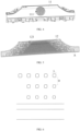
- FIG. 1 is a structural schematic diagram of a sound playing apparatus according to an embodiment of the present application.
- Embodiments of the present application provide a loudspeaker cover plate, a sound playing apparatus with the loudspeaker cover plate and a terminal with the sound playing apparatus, where the sound playing apparatus may be any apparatus capable of playing sound, such as a radio, player, sound box, speaker, laptop sound box, vehicle sound box, etc.
- the terminal may be any device with a sound playing apparatus, such as a laptop, vehicle, television, etc.
- the sound playing apparatus may be an apparatus configured to playing sound in the vehicle, as shown in FIG. 1 .
- the sound playing apparatus 100 may include a loudspeaker 20 and a loudspeaker cover plate 10 covering the loudspeaker 20.
- the loudspeaker 20 may amplify the sound and make it spread bigger and farther, and the loudspeaker cover plate 10 is configured to shield the loudspeaker 20 to prevent the loudspeaker 20 from being exposed to the air to provide protection for the loudspeaker 20.
- the loudspeaker cover plate 10 may also play a decorative role, so as to prevent the loudspeaker 20 from being exposed to the air and affecting the attractiveness of the sound playing apparatus 100, which is beneficial to improve the overall attractiveness of the interior of the vehicle as well as the user experience.
- the sound playing apparatus 100 may be provide in the vehicle to facilitate users to listen to music, navigation, etc.
- the vehicle may include a plurality of the sound playing apparatus 100, which may be evenly distributed in the interior of the vehicle.
- the sound playing apparatus 100 may be distributed in the dashboard housing, front side door, rear side door and other parts of the vehicle.
- the dashboard housing may be a structural component for enclosing the dashboard in the vehicle, and the dashboard is an instrument structural component for displaying information and data in the vehicle, where the dashboard housing may facilitate the arrangement of the dashboard and play a protective role for the dashboard.
- the sound playing apparatus 100 located on the dashboard housing may facilitate a driver to listen to the sound, while the sound playing apparatus 100 located at the front side door may facilitate a passenger in the front row to listen to the sound, and the sound playing apparatus 100 located at the rear side door may facilitate a passenger in the back row to listen to the sound.
- the sound playing apparatus 100 is distributed in multiple positions in the vehicle, so that the sound playing effect is effectively improved and the sound played by the vehicle surround the vehicle is evenly, so that passengers in different positions in the vehicle may clearly hear the sound, which is beneficial to improve the user experience.
- the vehicle may also include other structural components for realizing their functions, for example, the vehicle may also include a display apparatus, operation buttons, etc., where the display apparatus may be used to display driving information (such as speed, fuel quantity, fuel consumption, etc.), navigation information, music playing information, etc.
- driving information such as speed, fuel quantity, fuel consumption, etc.
- navigation information such as speed, fuel quantity, fuel consumption, etc.
- music playing information etc.
- the information on the display apparatus may be played by voice function, and spread out through the sound playing apparatus 100, so that the driver and the passenger may listen to it.
- Users may operate the display apparatus by operation buttons, for example, turning on navigation, playing music, selecting songs, adjusting the volume, etc., to meet the different requirements of users.
- the loudspeaker cover plate is usually a plastic piece. By opening mesh on the loudspeaker cover plate of the plastic piece, sound may spread outward through the mesh of the loudspeaker cover plate, so that the loudspeaker cover plate has sound permeability, which is beneficial to improve the sound playing effect of the sound playing apparatus.
- the material of the loudspeaker cover plate of the plastic piece is hard and the surface gloss is low, which makes the loudspeaker cover plate have poor touch and texture, reduces the attractiveness of the sound playing apparatus and affects the user experience.
- the present application provides a loudspeaker cover plate, the touch and the texture of the loudspeaker cover plate are effectively improved, the attractiveness of the sound playing apparatus is improved, and the user experience is improved.
- FIG. 2 is a structural schematic diagram of a loudspeaker cover plate according to an embodiment of the present application
- FIG. 3 is a structural schematic diagram of a loudspeaker cover plate connecting to a loudspeaker according to an embodiment of the present application
- FIG. 4 is a structural schematic diagram of a substrate according to an embodiment of the present application
- FIG. 5 is a structural schematic diagram of an appearance piece according to an embodiment of the present application.
- an embodiment of the present application provide a loudspeaker cover plate 10, including a substrate 11 and an appearance piece 12 covering the substrate 11, where the substrate 11 is the supporting component of the entire loudspeaker cover plate 10, playing a load-bearing role.
- the substrate 11 may provide rigid support for the loudspeaker cover plate 10, and a structural component which form the loudspeaker cover plate 10 may be centrally arranged on the substrate 11 to form a complete loudspeaker cover plate 10.
- the substrate 11 may also facilitate the installation of loudspeaker cover plate 10.
- the substrate 11 may be configured to connect to the loudspeaker 20, allowing the loudspeaker cover plate 10 to be connected to the loudspeaker 20 through the substrate 11.
- the substrate 11 and the loudspeaker 20 may be connected in a detachable manner, which facilitates the detachment of the loudspeaker cover plate 10 and facilitates the repairing and maintenance of the sound playing apparatus 100.
- the detachable connection between the substrate 11 and the loudspeaker 20 may be realized through ways such as clamping, fastening, bonding, and threaded connection.
- a first clamping part (not shown in the figures) may be provided on the loudspeaker 20, and a second clamping part (not shown in the figures) matched with the first clamping part may be provided on the substrate 11, and the substrate 11 may be clamped with the loudspeaker 20 through the matching of the first clamping part and the second clamping part.
- a threaded hole (not shown in the figures) may be provided on the substrate 11, and a mounting hole (not shown in the figures) may be provided on the loudspeaker 20.
- the loudspeaker cover plate 10 may also include a threaded fastener matched with the threaded hole, and the threaded fastener may pass through the mounting hole and be matched with the threaded hole, so that the substrate 11 and the loudspeaker 20 may be connected through the threaded fastener.
- connection between the substrate 11 and the loudspeaker 20 may also be realized in other ways. Specifically, the connection mode between the substrate 11 and the loudspeaker 20 may be selected and arranged according to specific scene requirements.
- the appearance piece 12 may be located on a surface of the substrate 11 away from the loudspeaker 20, that is, the appearance piece 12 is located on the viewing surface of the loudspeaker cover plate 10.
- the appearance piece 12 may play the role of decorating the loudspeaker cover plate 10 to improve the attractiveness of the loudspeaker cover plate 10, thereby improving the attractiveness of the interior of the vehicle.
- An edge part of the appearance piece 12 may be folded inward along an edge of the substrate 11, so that the edge part of the appearance piece 12 may be folded to a surface of the substrate 11 facing the loudspeaker 20, which is beneficial to improve the firmness and reliability of the connection between the appearance piece 12 and the substrate 11 as well as the overall structural stability and reliability of the loudspeaker cover plate 10.
- a plurality of first through holes 111 are arranged on the substrate 11, so that sound may propagate outward through the first through holes 111, thereby reducing or avoiding the obstruction on sound by the substrate 11 and facilitating the propagation of sound.
- a weight of the substrate 11 may be reduced, thereby reducing an overall weight of the loudspeaker cover plate 10, which is beneficial to meet the lightweight design requirements of the loudspeaker cover plate 10.
- the first through holes 111 may be centrally arranged and positioned opposite to the loudspeaker 20, so that sound may directly propagate outward through the first through holes 111 after being propagated from the loudspeaker 20. In this way, the obstruction on sound from other parts of the substrate 11 may be effectively reduced or avoided, thereby effectively improving the efficiency of sound propagation from the substrate 11.
- a shape of the first through holes 111 on the substrate 11 may be a circle, a square, a triangle or a trapezium.
- the shape of the first through holes 111 may also be irregular.
- the shape of the first through holes 111 at the edge may be a special shape, so that the first through holes 111 on the substrate 11 are arranged in a certain pattern to form a circular structure as a whole, thereby improving the sound permeability of the substrate 11.
- the shape of the first through holes 111 may be selected and arranged according to specific scene requirements.
- a plurality of second through holes 121 are arranged on the appearance piece 12, where at least some of the second through holes 121 are opposite to the first through holes 111, so that sound may propagate outward through the first through holes 111 and the second through holes 121, thereby reducing or avoiding the obstruction on sound by the appearance piece 12, which is beneficial to improve the overall sound permeability of the loudspeaker cover plate 10 as well as the sound playing effect of the sound playing apparatus 100.
- a forming material of the appearance piece is a leather material, comparing with the plastic loudspeaker cover plate 10, the leather appearance piece 12 is soft, so that the hardness of the loudspeaker cover plate 10 may be effectively reduced, and good touch experience may be brought to a user during touch, thereby effectively improving the touch feeling of the loudspeaker cover plate 10.
- lines on the surface of the leather appearance piece 12 are relatively natural and good in glossiness, so that the texture of the loudspeaker cover plate 10 may be effectively improved, the overall attractiveness of the loudspeaker cover plate 10 is improved, the interior of a vehicle looks more attractive and elegant, which is beneficial to improve the overall attractiveness and the feeling of high class of the interior of the vehicle as well as the user experience.
- the forming material of the appearance piece at least includes natural leather (such as cowhide, pigskin, horse skin or sheepskin, etc.), artificial leather, recycled leather or synthetic leather, etc. All the foregoing leather materials have good softness and glossiness, the touch and texture of the appearance piece 12 may be effectively improved, which is beneficial to improve the overall quality and attractiveness of the loudspeaker cover plate 10, thereby improving the attractiveness of the interior of the vehicle as well as the user experience.
- natural leather such as cowhide, pigskin, horse skin or sheepskin, etc.
- artificial leather recycled leather or synthetic leather
- a shape of the second through holes 121 may be a square, a circle and a triangle, etc.
- the shape of the second through holes 121 may be a square.
- the shape of the second through holes 121 may also be selected and arranged according to specific scene requirements.
- first through holes 111 and the second through holes 121 may be the same or different, and embodiments of the present application is not limited.
- FIG. 6 is an enlarged view of the area A of FIG. 5 .
- a size of the second through holes 121 may be L, and a value range of L may be 2.5 mm to 5 mm.
- the size of the second through holes 121 may be 2.5 mm, 3.5 mm or 4.5 mm, etc.
- the sound permeability of the appearance piece 12 is effectively improved, reducing or avoiding reduction of the sound permeability of the appearance piece 12 caused by the size of the second through holes 121 being too small, which is beneficial to improve the sound effect of the sound playing apparatus 100.
- the effect of the oversized diameter of the second through holes 121 on the attractiveness of the appearance piece 12 may be reduced or avoided, which is beneficial to improve the overall attractiveness of the loudspeaker cover plate 10.
- the size L may refer to a diameter dimension of the circle, that is, the diameter of the second through holes 121 may be 2.5 mm to 5 mm.
- the size L may refer to a side length of the square, that is, the side length of the second through holes 121 may be 2.5 mm to 5 mm.
- a distance between two adjacent second through holes 121 may be D, and a value range of D may be 1.25 mm to 10 mm.
- the distance between two adjacent second through holes 121 may be 1.25 mm, 2 mm, 5 mm, 8 mm, etc.
- the obstruction on sound caused by the excessive distance between the two adjacent second through holes 121 may be reduced or avoided, which is beneficial to improve the sound permeability of the appearance piece 12 as well as the sound effect of the sound playing apparatus 100.
- the value of the distance D between any two adjacent first through holes 111 may not be equal. For example, it may enable the distance between the second through holes 121 opposite to the first through holes 111 (i.e. opposite to the loudspeaker 20) to be closer, while the distance between the second through holes 121 far away from the first through holes 111 to be relatively farther.
- the second through holes 121 on the part of the appearance piece 12 opposite to the first through holes 111 are relatively dense, so that the sound penetration is improved, thereby improving the sound permeability of the appearance piece 12.
- the second through holes 121 on the part of the appearance piece 12 far away from the first through holes 111 are relatively scattered, so that the strength of the appearance piece 12 is improved, reducing or avoiding the broken or damage of the appearance piece 12 caused by the dense second through holes 121, which is beneficial to improve the service life of the appearance piece 12.
- a size of the first through holes 111 may be larger than the size of the second through holes 121.
- the first through holes 111 it is convenient to enable the first through holes 111 to opposite to the second through holes 121, reduce or avoid the misalignment between the first through holes 111 and the second through holes 121 caused by the size of the first through holes 111 being too small, and prevent the sound from being blocked due to the misalignment between the first through holes 111 and the second through holes 121, thus the sound permeability of the loudspeaker cover plate 10 is effectively improved and the sound propagation effect is improved.
- enabling the size of the first through holes 111 to be larger may be beneficial to reduce the weight of the substrate 11, thereby reducing the overall weight of the loudspeaker cover plate 10, and improving the lightweight design requirements of the loudspeaker cover plate 10.
- the loudspeaker cover plate 10 further includes a base fabric layer (not shown in the figures), the base fabric layer may be connected to the appearance piece 12, and the base fabric may locate on a surface of the appearance piece 12 facing the substrate 11.
- the base fabric layer and the appearance piece 12 may be connected by bonding or the like.
- the base fabric layer has high strength and low elasticity.
- the elasticity of the appearance piece 12 may be reduced, the elastic deformation of the appearance piece 12 may be reduced or avoided, the deformation of the second through holes 121 caused by the deformation of the appearance piece 12 may be avoided, and the appearance of the loudspeaker cover plate 10 may be prevented from being adversely affected by the deformation of the appearance piece 12 and the second through holes 121, which is beneficial to improve the overall attractiveness of the loudspeaker cover plate 10.
- FIG. 7 is an exploded schematic diagram of a loudspeaker cover plate according to an embodiment of the present application
- FIG. 8 is a structural schematic diagram of a flexible layer according to an embodiment of the present application.
- the loudspeaker cover plate 10 further includes a flexible layer 13, the flexible layer 13 is located between the appearance piece 12 and the substrate 11.
- the flexible layer 13 may be a structural component made of a flexible material, which may play a flexible supporting role for the appearance piece 12, so as to realize a good shaping effect on the appearance piece 12, and may reduce or avoid the appearance of the imprint of the first through holes 111 on the appearance piece 12 due to the direct contact of the appearance piece 12 with the substrate 11, which is beneficial to improve the attractiveness of the loudspeaker cover plate 10.
- the flexible layer 13 may effectively improve the flexibility of the surface of the loudspeaker cover plate 10, which is beneficial to further improve the touch of the loudspeaker cover plate as well as the user experience.
- the flexible layer may be a 3D mesh fabric (abbreviation is 3D mesh).
- 3D mesh fabric includes two layers of base fabric and elastic woven materials arranged between the two layers of base fabric.
- the 3D mesh fabric has good support, which may effectively improve the supporting effect of the appearance piece 12, reduce or avoid the adverse effect of the first through holes 111 on the surface of the appearance piece 12, thereby the aesthetics of the loudspeaker cover plate 10 is effectively improved.
- the 3D mesh fabric also has good air permeability, which may enable the flexible layer 13 has good sound permeability, and may reduce or avoid the obstruction on sound by the flexible layer 13, thereby the sound permeability of the loudspeaker cover plate 10 is effectively improved, and the sound playing effect of the sound playing apparatus 100 is improved.
- the 3D mesh fabric has good elasticity, which may effectively improve the softness of the surface of the loudspeaker cover plate 10, thereby the touch of the loudspeaker cover plate 10 is improved, and the user experience is improved.
- the flexible layer 13 has a certain shielding effect, which may shield the first through holes 111, prevent the loudspeaker 20 and other structures on which from being exposed through the first through holes 111 and the second through holes 121, which is beneficial to improve the attractiveness of the loudspeaker cover plate 10.
- a thickness of the flexible layer 13 may be 2 mm to 3 mm, which may effectively improve the shaping effect of the flexible layer 13, and improve the attractiveness of the loudspeaker cover plate 10.
- the terms “installation”, “connection”, “coupled”, “fixation”, etc. should be broadly understood, for example, they may be fixed connections, detachable connections, or integrated; it may be directly connected or indirectly connected through an intermediate medium, which may establish the internal connection or interaction relationship between two components.
- the specific meanings of the above terms in the present invention may be understood according to the specific situation.
- the terms “first”, “second”, etc. are only used for descriptive purposes and cannot be understood as indicating or implying relative importance or implying the number of technical features indicated.
Landscapes
- Engineering & Computer Science (AREA)
- Physics & Mathematics (AREA)
- Acoustics & Sound (AREA)
- Signal Processing (AREA)
- Manufacturing & Machinery (AREA)
- Fittings On The Vehicle Exterior For Carrying Loads, And Devices For Holding Or Mounting Articles (AREA)
- Details Of Audible-Bandwidth Transducers (AREA)
Abstract
Description
- The present application claims priority to
Chinese Patent Application No. 202210673550.4 filed with China National Intellectual Property Administration on June 13, 2022 - The present invention relates to the technical field of loudspeakers, in particular to a loudspeaker cover plate, a sound playing apparatus and a terminal.
- Sound box refers to a sound playing apparatus that may convert audio signals into sound. It may amplify the audio signals and then play back the sound from the sound box itself to make the sound louder. Sound box is the terminal of the whole sound system, and its function is to convert audio electric energy into corresponding sound energy and radiate which into space. Sound box is an extremely important part of sound system, which is responsible for converting electrical signals into acoustic signals for people's ears to listen to directly. Sound box has a very wide range of applications, such as radios, players, notebooks, vehicles and other devices with sound generation functions.
- Taking the application of sound boxes in vehicles as an example, typically, sound boxes include a loudspeaker and a loudspeaker cover plate covered on top of the loudspeaker, where the loudspeaker is configured to propagate sound further and larger, while the loudspeaker cover plate is configured to shield the loudspeaker to decorate the sound box and improve the attractiveness. At present, the loudspeaker cover plate is usually a plastic piece. By opening a mesh on the loudspeaker cover plate of the plastic piece, the sound may be transmitted through the mesh.
- However, the touch and texture of the loudspeaker cover plate are poor, which reduces the attractiveness of the speaker and affects the user experience.
- The present invention provides a loudspeaker cover plate, a sound playing apparatus and a terminal, so as to solve the problems that the existing loudspeaker cover plate has poor texture and texture, reduces the attractiveness of a sound box and affects the user experience.
- The first aspect of the present invention provides a loudspeaker cover plate, which is configured to connect to a loudspeaker, and includes a substrate and an appearance piece covering the substrate, the substrate is configured to connect to the loudspeaker, and the appearance piece is located on a surface of the substrate away from the loudspeaker;
- a plurality of first through holes are arranged on the substrate, a plurality of second through holes are arranged on the appearance piece, and at least some of the second through holes are opposite to the first through holes; and
- a forming material of the appearance piece is a leather material.
- A forming material of the appearance piece is a leather material. The material of the leather appearance piece is soft, so that the hardness of the loudspeaker cover plate may be effectively reduced, and good touch experience may be brought to a user during touch, thereby effectively improving the touch feeling of the loudspeaker cover plate. Moreover, lines on the surface of the leather appearance piece are relatively natural and good in glossiness, so that the texture of the loudspeaker cover plate may be effectively improved, the overall attractiveness of the loudspeaker cover plate is improved, the interior of a vehicle looks more attractive and elegant, which is beneficial to improve the overall attractiveness and the feeling of high class of the interior of the vehicle as well as the user experience.
- In a possible implementation, the loudspeaker cover plate further includes a flexible layer, the flexible layer is located between the appearance piece and the substrate.
- In a possible implementation, the loudspeaker cover plate further includes a base fabric layer, the base fabric layer is connected to the appearance piece, and the base fabric is located on a surface of the appearance piece facing the substrate.
- In a possible implementation, the forming material of the appearance piece at least includes natural leather, artificial leather, recycled leather or synthetic leather.
- In a possible implementation, a size of the first through holes is larger than a size of the second through holes.
- In a possible implementation, a shape of the second through holes at least comprises a square, a circle and a triangle.
- In a possible implementation, the size of the second through holes is 2.5 mm to 5 mm, and a distance between the two adjacent second through holes is 1.25 mm to 10 mm.
- In a possible implementation, the flexible layer is a 3D mesh fabric.
- The second aspect of the present invention provides a sound playing apparatus, at least includes a loudspeaker and any one of the foregoing loudspeaker cover plate, where the loudspeaker cover plate covers the loudspeaker.
- The third aspect of the present invention provides a terminal, at least includes the foregoing sound playing apparatus.
- To describe the technical solutions in embodiments of the present invention or in the prior art more clearly, the following briefly introduces the accompanying drawings needed for describing the embodiments or the prior art. Apparently, the accompanying drawings in the following description illustrate some embodiments of the present invention, and persons of ordinary skill in the art may still derive other drawings from these accompanying drawings without creative effort.
-
FIG. 1 is a structural schematic diagram of a sound playing apparatus according to an embodiment of the present application. -
FIG. 2 is a structural schematic diagram of a loudspeaker cover plate according to an embodiment of the present application. -
FIG. 3 is a structural schematic diagram of a loudspeaker cover plate connecting to a loudspeaker according to an embodiment of the present application. -
FIG. 4 is a structural schematic diagram of a substrate according to an embodiment of the present application. -
FIG. 5 is a structural schematic diagram of an appearance piece according to an embodiment of the present application. -
FIG. 6 is an enlarged view of the area A ofFIG. 5 . -
FIG. 7 is an exploded schematic diagram of a loudspeaker cover plate according to an embodiment of the present application. -
FIG. 8 is a structural schematic diagram of a flexible layer according to an embodiment of the present application. -
- 100 - Sound playing apparatus;
- 10 - Loudspeaker cover plate;
- 11 - Substrate;
- 111 - First through hole;
- 12 - Appearance piece;
- 121- Second through hole;
- 13- Flexible layer;
- 20- Loudspeaker.
- To make the objectives, technical solutions, and advantages of embodiments of the present invention clearer, the following clearly and comprehensively describes the technical solutions in embodiments of the present invention with reference to the accompanying drawings in the embodiments of the present invention. Apparently, the described embodiments are a part rather than all embodiments of the present invention. All other embodiments obtained by persons of ordinary skill in the art based on the embodiments of the present invention without creative effort shall fall within the protection scope of the present invention.
-
FIG. 1 is a structural schematic diagram of a sound playing apparatus according to an embodiment of the present application. - Embodiments of the present application provide a loudspeaker cover plate, a sound playing apparatus with the loudspeaker cover plate and a terminal with the sound playing apparatus, where the sound playing apparatus may be any apparatus capable of playing sound, such as a radio, player, sound box, speaker, laptop sound box, vehicle sound box, etc. The terminal may be any device with a sound playing apparatus, such as a laptop, vehicle, television, etc.
- Taking the terminal as an example of a vehicle, the sound playing apparatus may be an apparatus configured to playing sound in the vehicle, as shown in
FIG. 1 . The sound playingapparatus 100 may include aloudspeaker 20 and aloudspeaker cover plate 10 covering theloudspeaker 20. Theloudspeaker 20 may amplify the sound and make it spread bigger and farther, and theloudspeaker cover plate 10 is configured to shield theloudspeaker 20 to prevent theloudspeaker 20 from being exposed to the air to provide protection for theloudspeaker 20. In addition, theloudspeaker cover plate 10 may also play a decorative role, so as to prevent theloudspeaker 20 from being exposed to the air and affecting the attractiveness of the sound playingapparatus 100, which is beneficial to improve the overall attractiveness of the interior of the vehicle as well as the user experience. - The sound playing
apparatus 100 may be provide in the vehicle to facilitate users to listen to music, navigation, etc. For example, the vehicle may include a plurality of the sound playingapparatus 100, which may be evenly distributed in the interior of the vehicle. For example, thesound playing apparatus 100 may be distributed in the dashboard housing, front side door, rear side door and other parts of the vehicle. The dashboard housing may be a structural component for enclosing the dashboard in the vehicle, and the dashboard is an instrument structural component for displaying information and data in the vehicle, where the dashboard housing may facilitate the arrangement of the dashboard and play a protective role for the dashboard. - The
sound playing apparatus 100 located on the dashboard housing may facilitate a driver to listen to the sound, while thesound playing apparatus 100 located at the front side door may facilitate a passenger in the front row to listen to the sound, and thesound playing apparatus 100 located at the rear side door may facilitate a passenger in the back row to listen to the sound. In this way, thesound playing apparatus 100 is distributed in multiple positions in the vehicle, so that the sound playing effect is effectively improved and the sound played by the vehicle surround the vehicle is evenly, so that passengers in different positions in the vehicle may clearly hear the sound, which is beneficial to improve the user experience. - The vehicle may also include other structural components for realizing their functions, for example, the vehicle may also include a display apparatus, operation buttons, etc., where the display apparatus may be used to display driving information (such as speed, fuel quantity, fuel consumption, etc.), navigation information, music playing information, etc. The information on the display apparatus may be played by voice function, and spread out through the
sound playing apparatus 100, so that the driver and the passenger may listen to it. - Users may operate the display apparatus by operation buttons, for example, turning on navigation, playing music, selecting songs, adjusting the volume, etc., to meet the different requirements of users.
- At present, the loudspeaker cover plate is usually a plastic piece. By opening mesh on the loudspeaker cover plate of the plastic piece, sound may spread outward through the mesh of the loudspeaker cover plate, so that the loudspeaker cover plate has sound permeability, which is beneficial to improve the sound playing effect of the sound playing apparatus.
- However, the material of the loudspeaker cover plate of the plastic piece is hard and the surface gloss is low, which makes the loudspeaker cover plate have poor touch and texture, reduces the attractiveness of the sound playing apparatus and affects the user experience.
- In response to the foregoing problem, the present application provides a loudspeaker cover plate, the touch and the texture of the loudspeaker cover plate are effectively improved, the attractiveness of the sound playing apparatus is improved, and the user experience is improved.
-
FIG. 2 is a structural schematic diagram of a loudspeaker cover plate according to an embodiment of the present application,FIG. 3 is a structural schematic diagram of a loudspeaker cover plate connecting to a loudspeaker according to an embodiment of the present application,FIG. 4 is a structural schematic diagram of a substrate according to an embodiment of the present application,FIG. 5 is a structural schematic diagram of an appearance piece according to an embodiment of the present application. - As shown in
FIG. 2 , an embodiment of the present application provide aloudspeaker cover plate 10, including asubstrate 11 and anappearance piece 12 covering thesubstrate 11, where thesubstrate 11 is the supporting component of the entireloudspeaker cover plate 10, playing a load-bearing role. Thesubstrate 11 may provide rigid support for theloudspeaker cover plate 10, and a structural component which form theloudspeaker cover plate 10 may be centrally arranged on thesubstrate 11 to form a completeloudspeaker cover plate 10. In addition, thesubstrate 11 may also facilitate the installation ofloudspeaker cover plate 10. For example, as shown inFIG. 3 , thesubstrate 11 may be configured to connect to theloudspeaker 20, allowing theloudspeaker cover plate 10 to be connected to theloudspeaker 20 through thesubstrate 11. - The
substrate 11 and theloudspeaker 20 may be connected in a detachable manner, which facilitates the detachment of theloudspeaker cover plate 10 and facilitates the repairing and maintenance of thesound playing apparatus 100. For example, the detachable connection between thesubstrate 11 and theloudspeaker 20 may be realized through ways such as clamping, fastening, bonding, and threaded connection. - For example, a first clamping part (not shown in the figures) may be provided on the
loudspeaker 20, and a second clamping part (not shown in the figures) matched with the first clamping part may be provided on thesubstrate 11, and thesubstrate 11 may be clamped with theloudspeaker 20 through the matching of the first clamping part and the second clamping part. - Alternatively, a threaded hole (not shown in the figures) may be provided on the
substrate 11, and a mounting hole (not shown in the figures) may be provided on theloudspeaker 20. Theloudspeaker cover plate 10 may also include a threaded fastener matched with the threaded hole, and the threaded fastener may pass through the mounting hole and be matched with the threaded hole, so that thesubstrate 11 and theloudspeaker 20 may be connected through the threaded fastener. - Alternatively, in some examples, the connection between the
substrate 11 and theloudspeaker 20 may also be realized in other ways. Specifically, the connection mode between thesubstrate 11 and theloudspeaker 20 may be selected and arranged according to specific scene requirements. - The
appearance piece 12 may be located on a surface of thesubstrate 11 away from theloudspeaker 20, that is, theappearance piece 12 is located on the viewing surface of theloudspeaker cover plate 10. Theappearance piece 12 may play the role of decorating theloudspeaker cover plate 10 to improve the attractiveness of theloudspeaker cover plate 10, thereby improving the attractiveness of the interior of the vehicle. - An edge part of the
appearance piece 12 may be folded inward along an edge of thesubstrate 11, so that the edge part of theappearance piece 12 may be folded to a surface of thesubstrate 11 facing theloudspeaker 20, which is beneficial to improve the firmness and reliability of the connection between theappearance piece 12 and thesubstrate 11 as well as the overall structural stability and reliability of theloudspeaker cover plate 10. - As shown in
FIG. 4 , a plurality of first throughholes 111 are arranged on thesubstrate 11, so that sound may propagate outward through the first throughholes 111, thereby reducing or avoiding the obstruction on sound by thesubstrate 11 and facilitating the propagation of sound. In addition, a weight of thesubstrate 11 may be reduced, thereby reducing an overall weight of theloudspeaker cover plate 10, which is beneficial to meet the lightweight design requirements of theloudspeaker cover plate 10. - The first through
holes 111 may be centrally arranged and positioned opposite to theloudspeaker 20, so that sound may directly propagate outward through the first throughholes 111 after being propagated from theloudspeaker 20. In this way, the obstruction on sound from other parts of thesubstrate 11 may be effectively reduced or avoided, thereby effectively improving the efficiency of sound propagation from thesubstrate 11. - A shape of the first through
holes 111 on thesubstrate 11 may be a circle, a square, a triangle or a trapezium. - Alternatively, in some examples, the shape of the first through
holes 111 may also be irregular. For example, as shown inFIG. 4 , the shape of the first throughholes 111 at the edge may be a special shape, so that the first throughholes 111 on thesubstrate 11 are arranged in a certain pattern to form a circular structure as a whole, thereby improving the sound permeability of thesubstrate 11. Specifically, the shape of the first throughholes 111 may be selected and arranged according to specific scene requirements. - As shown in
FIG. 5 , a plurality of second throughholes 121 are arranged on theappearance piece 12, where at least some of the second throughholes 121 are opposite to the first throughholes 111, so that sound may propagate outward through the first throughholes 111 and the second throughholes 121, thereby reducing or avoiding the obstruction on sound by theappearance piece 12, which is beneficial to improve the overall sound permeability of theloudspeaker cover plate 10 as well as the sound playing effect of thesound playing apparatus 100. - A forming material of the appearance piece is a leather material, comparing with the plastic
loudspeaker cover plate 10, theleather appearance piece 12 is soft, so that the hardness of theloudspeaker cover plate 10 may be effectively reduced, and good touch experience may be brought to a user during touch, thereby effectively improving the touch feeling of theloudspeaker cover plate 10. Moreover, comparing with the plasticloudspeaker cover plate 10, lines on the surface of theleather appearance piece 12 are relatively natural and good in glossiness, so that the texture of theloudspeaker cover plate 10 may be effectively improved, the overall attractiveness of theloudspeaker cover plate 10 is improved, the interior of a vehicle looks more attractive and elegant, which is beneficial to improve the overall attractiveness and the feeling of high class of the interior of the vehicle as well as the user experience. - The forming material of the appearance piece at least includes natural leather (such as cowhide, pigskin, horse skin or sheepskin, etc.), artificial leather, recycled leather or synthetic leather, etc. All the foregoing leather materials have good softness and glossiness, the touch and texture of the
appearance piece 12 may be effectively improved, which is beneficial to improve the overall quality and attractiveness of theloudspeaker cover plate 10, thereby improving the attractiveness of the interior of the vehicle as well as the user experience. - In the embodiments of the present application, a shape of the second through
holes 121 may be a square, a circle and a triangle, etc. For example, as shown inFIG. 5 , the shape of the second throughholes 121 may be a square. Specifically, the shape of the second throughholes 121 may also be selected and arranged according to specific scene requirements. - It should be understood that the shapes of the first through
holes 111 and the second throughholes 121 may be the same or different, and embodiments of the present application is not limited. -
FIG. 6 is an enlarged view of the area A ofFIG. 5 . - As shown in
FIG. 6 , a size of the second throughholes 121 may be L, and a value range of L may be 2.5 mm to 5 mm. For example, the size of the second throughholes 121 may be 2.5 mm, 3.5 mm or 4.5 mm, etc. In this way, the sound permeability of theappearance piece 12 is effectively improved, reducing or avoiding reduction of the sound permeability of theappearance piece 12 caused by the size of the second throughholes 121 being too small, which is beneficial to improve the sound effect of thesound playing apparatus 100. In addition, the effect of the oversized diameter of the second throughholes 121 on the attractiveness of theappearance piece 12 may be reduced or avoided, which is beneficial to improve the overall attractiveness of theloudspeaker cover plate 10. - When the shape of the second through
holes 121 is the circle, the size L may refer to a diameter dimension of the circle, that is, the diameter of the second throughholes 121 may be 2.5 mm to 5 mm. When the shape of the second throughholes 121 is the square, the size L may refer to a side length of the square, that is, the side length of the second throughholes 121 may be 2.5 mm to 5 mm. - As shown in
FIG. 6 , a distance between two adjacent second throughholes 121 may be D, and a value range of D may be 1.25 mm to 10 mm. For example, the distance between two adjacent second throughholes 121 may be 1.25 mm, 2 mm, 5 mm, 8 mm, etc. In this way, reduction of the strength of theappearance piece 12 caused by the distance between two adjacent second throughholes 121 being too small may be reduced or avoided, and theappearance piece 12 may be prevented from being broken, which is beneficial to improve the structural stability and reliability of theappearance piece 12. In addition, the obstruction on sound caused by the excessive distance between the two adjacent second throughholes 121 may be reduced or avoided, which is beneficial to improve the sound permeability of theappearance piece 12 as well as the sound effect of thesound playing apparatus 100. - It should be noted that for the
appearance piece 12, the value of the distance D between any two adjacent first throughholes 111 may not be equal. For example, it may enable the distance between the second throughholes 121 opposite to the first through holes 111 (i.e. opposite to the loudspeaker 20) to be closer, while the distance between the second throughholes 121 far away from the first throughholes 111 to be relatively farther. In other words, the second throughholes 121 on the part of theappearance piece 12 opposite to the first throughholes 111 are relatively dense, so that the sound penetration is improved, thereby improving the sound permeability of theappearance piece 12. On the other hand, the second throughholes 121 on the part of theappearance piece 12 far away from the first throughholes 111 are relatively scattered, so that the strength of theappearance piece 12 is improved, reducing or avoiding the broken or damage of theappearance piece 12 caused by the dense second throughholes 121, which is beneficial to improve the service life of theappearance piece 12. - In the embodiments of the present application, a size of the first through
holes 111 may be larger than the size of the second throughholes 121. For example, it takes the shapes of the first throughholes 111 and the second throughholes 121 being squares as an example, a side length of the first throughholes 111 may be larger than a side length of the second throughholes 121. In this way, the sound shielding of thesubstrate 11 may be further reduced, the sound permeability of thesubstrate 11 may be improved, and the sound propagation effect may be improved. - In addition, it is convenient to enable the first through
holes 111 to opposite to the second throughholes 121, reduce or avoid the misalignment between the first throughholes 111 and the second throughholes 121 caused by the size of the first throughholes 111 being too small, and prevent the sound from being blocked due to the misalignment between the first throughholes 111 and the second throughholes 121, thus the sound permeability of theloudspeaker cover plate 10 is effectively improved and the sound propagation effect is improved. - Moreover, enabling the size of the first through
holes 111 to be larger may be beneficial to reduce the weight of thesubstrate 11, thereby reducing the overall weight of theloudspeaker cover plate 10, and improving the lightweight design requirements of theloudspeaker cover plate 10. - In the embodiments of the present application, the
loudspeaker cover plate 10 further includes a base fabric layer (not shown in the figures), the base fabric layer may be connected to theappearance piece 12, and the base fabric may locate on a surface of theappearance piece 12 facing thesubstrate 11. For example, the base fabric layer and theappearance piece 12 may be connected by bonding or the like. The base fabric layer has high strength and low elasticity. By connecting the base fabric layer with theappearance piece 12, the strength of theappearance piece 12 may be effectively improved and theappearance piece 12 may be avoided from being broken. - In addition, the elasticity of the
appearance piece 12 may be reduced, the elastic deformation of theappearance piece 12 may be reduced or avoided, the deformation of the second throughholes 121 caused by the deformation of theappearance piece 12 may be avoided, and the appearance of theloudspeaker cover plate 10 may be prevented from being adversely affected by the deformation of theappearance piece 12 and the second throughholes 121, which is beneficial to improve the overall attractiveness of theloudspeaker cover plate 10. -
FIG. 7 is an exploded schematic diagram of a loudspeaker cover plate according to an embodiment of the present application,FIG. 8 is a structural schematic diagram of a flexible layer according to an embodiment of the present application. - As shown in
FIG. 7 , in the embodiments of the present application, theloudspeaker cover plate 10 further includes aflexible layer 13, theflexible layer 13 is located between theappearance piece 12 and thesubstrate 11. Theflexible layer 13 may be a structural component made of a flexible material, which may play a flexible supporting role for theappearance piece 12, so as to realize a good shaping effect on theappearance piece 12, and may reduce or avoid the appearance of the imprint of the first throughholes 111 on theappearance piece 12 due to the direct contact of theappearance piece 12 with thesubstrate 11, which is beneficial to improve the attractiveness of theloudspeaker cover plate 10. - In addition, the
flexible layer 13 may effectively improve the flexibility of the surface of theloudspeaker cover plate 10, which is beneficial to further improve the touch of the loudspeaker cover plate as well as the user experience. - The flexible layer may be a 3D mesh fabric (abbreviation is 3D mesh). 3D mesh fabric includes two layers of base fabric and elastic woven materials arranged between the two layers of base fabric. The 3D mesh fabric has good support, which may effectively improve the supporting effect of the
appearance piece 12, reduce or avoid the adverse effect of the first throughholes 111 on the surface of theappearance piece 12, thereby the aesthetics of theloudspeaker cover plate 10 is effectively improved. - Moreover, the 3D mesh fabric also has good air permeability, which may enable the
flexible layer 13 has good sound permeability, and may reduce or avoid the obstruction on sound by theflexible layer 13, thereby the sound permeability of theloudspeaker cover plate 10 is effectively improved, and the sound playing effect of thesound playing apparatus 100 is improved. - In addition, the 3D mesh fabric has good elasticity, which may effectively improve the softness of the surface of the
loudspeaker cover plate 10, thereby the touch of theloudspeaker cover plate 10 is improved, and the user experience is improved. In addition, theflexible layer 13 has a certain shielding effect, which may shield the first throughholes 111, prevent theloudspeaker 20 and other structures on which from being exposed through the first throughholes 111 and the second throughholes 121, which is beneficial to improve the attractiveness of theloudspeaker cover plate 10. - A thickness of the
flexible layer 13 may be 2 mm to 3 mm, which may effectively improve the shaping effect of theflexible layer 13, and improve the attractiveness of theloudspeaker cover plate 10. - In the description of the present invention, it should be understood that the terms "center", "longitudinal", "transverse", "length", "width", "thickness", "up", "down", "front", "back", "left", "right", "vertical", "horizontal", "top", "bottom", "inside", "outside" and other directional or positional relationships indicated are based on the directional or positional relationships shown in the accompanying drawings, merely for the convenience of describing the present invention and simplifying the description, and do not indicate or imply that the apparatus or element referred to must have a specific orientation, be constructed and operated in a specific orientation, and therefore cannot be understood as a limitation of the present invention.
- In the description of the present invention, it should be understood that the terms "including" and "having" and any variations thereof used herein are intended to cover non exclusive inclusions, such as processes, methods, systems, products or devices that contain a series of steps or units that are not necessarily limited to those steps or units clearly listed, but may include other steps or units that are not clearly listed or inherent to these processes, methods, products or devices.
- Unless otherwise specified and limited, the terms "installation", "connection", "coupled", "fixation", etc. should be broadly understood, for example, they may be fixed connections, detachable connections, or integrated; it may be directly connected or indirectly connected through an intermediate medium, which may establish the internal connection or interaction relationship between two components. For ordinary skilled in the art, the specific meanings of the above terms in the present invention may be understood according to the specific situation. In addition, the terms "first", "second", etc. are only used for descriptive purposes and cannot be understood as indicating or implying relative importance or implying the number of technical features indicated.
- Finally, it should be noted that the foregoing embodiments are merely intended for describing the technical solutions of the present invention other than limiting the present invention. Although the present invention is described in detail with reference to the foregoing embodiments, persons of ordinary skill in the art should understand that they may still make modifications to the technical solutions described in the foregoing embodiments or make equivalent substitutions to some or all technical features thereof, without departing from the spirit and scope of the technical solutions of embodiments of the present invention.
Claims (10)
- A loudspeaker cover plate, configured to connect to a loudspeaker, wherein the loudspeaker cover plate comprises a substrate and an appearance piece covering the substrate, the substrate is configured to connect to the loudspeaker, and the appearance piece is located on a surface of the substrate away from the loudspeaker;a plurality of first through holes are arranged on the substrate, a plurality of second through holes are arranged on the appearance piece, and at least some of the second through holes are opposite to the first through holes; anda forming material of the appearance piece is a leather material.
- The loudspeaker cover plate according to claim 1, further comprising a flexible layer, wherein the flexible layer is located between the appearance piece and the substrate.
- The loudspeaker cover plate according to claim 1 or 2, further comprising a base fabric layer, wherein the base fabric layer is connected to the appearance piece, and the base fabric is located on a surface of the appearance piece facing the substrate.
- The loudspeaker cover plate according to claim 1 or 2, wherein the forming material of the appearance piece at least comprises natural leather, artificial leather, recycled leather or synthetic leather.
- The loudspeaker cover plate according to claim 1 or 2, wherein a size of the first through holes is larger than a size of the second through holes.
- The loudspeaker cover plate according to claim 1 or 2, wherein a shape of the second through holes at least comprises a square, a circle and a triangle.
- The loudspeaker cover plate according to claim 1 or 2, wherein the size of the second through holes is 2.5 mm to 5 mm, and a distance between the two adjacent second through holes is 1.25 mm to 10 mm.
- The loudspeaker cover plate according to claim 2, wherein the flexible layer is a 3D mesh fabric.
- A sound playing apparatus, at least comprising a loudspeaker and the loudspeaker cover plate according to any one of claims 1-8, wherein the loudspeaker cover plate covers the loudspeaker.
- A terminal, at least comprising the sound playing apparatus according to claim 9.
Applications Claiming Priority (2)
| Application Number | Priority Date | Filing Date | Title |
|---|---|---|---|
| CN202210673550.4A CN115086811A (en) | 2022-06-13 | 2022-06-13 | Loudspeaker cover plate, broadcasting device and terminal |
| PCT/CN2023/095908 WO2023241323A1 (en) | 2022-06-13 | 2023-05-23 | Loudspeaker cover plate, sound playing device and terminal |
Publications (2)
| Publication Number | Publication Date |
|---|---|
| EP4539494A1 true EP4539494A1 (en) | 2025-04-16 |
| EP4539494A4 EP4539494A4 (en) | 2025-10-08 |
Family
ID=83250827
Family Applications (1)
| Application Number | Title | Priority Date | Filing Date |
|---|---|---|---|
| EP23822893.6A Pending EP4539494A4 (en) | 2022-06-13 | 2023-05-23 | SPEAKER COVER PLATE, SOUND DEVICE AND TERMINAL |
Country Status (4)
| Country | Link |
|---|---|
| US (1) | US20250358555A1 (en) |
| EP (1) | EP4539494A4 (en) |
| CN (1) | CN115086811A (en) |
| WO (1) | WO2023241323A1 (en) |
Families Citing this family (2)
| Publication number | Priority date | Publication date | Assignee | Title |
|---|---|---|---|---|
| KR20240040220A (en) * | 2022-09-21 | 2024-03-28 | (주)대한솔루션 | Headliner for vehicle with speaker |
| CN117022138A (en) * | 2023-08-02 | 2023-11-10 | 浙江极氪智能科技有限公司 | Speaker cover covering method and speaker cover |
Family Cites Families (7)
| Publication number | Priority date | Publication date | Assignee | Title |
|---|---|---|---|---|
| US20070187173A1 (en) * | 2006-02-14 | 2007-08-16 | Price Carl J | Speaker grille |
| US8670581B2 (en) * | 2006-04-14 | 2014-03-11 | Murray R. Harman | Electrostatic loudspeaker capable of dispersing sound both horizontally and vertically |
| DE102011008995A1 (en) * | 2011-01-19 | 2012-06-06 | Daimler Ag | Speaker cover i.e. rear stereo console, for motor car speaker, has sound-permeable grating region with hole pattern, which comprises multiple holes and exhibits minimum degree of permeability for specific frequency range speaker |
| CN207573563U (en) * | 2017-12-19 | 2018-07-03 | 东莞市爱高音响有限公司 | A kind of Novel sound box |
| CN210381274U (en) * | 2019-09-25 | 2020-04-21 | Tcl-罗格朗国际电工(惠州)有限公司 | Sound structure and intercom device |
| DE102020003325A1 (en) * | 2020-06-03 | 2020-10-22 | Daimler Ag | Illuminable speaker cover |
| CN216684309U (en) * | 2021-12-28 | 2022-06-07 | 蔚来汽车科技(安徽)有限公司 | Speaker cover integrated on vehicle door, vehicle door and vehicle |
-
2022
- 2022-06-13 CN CN202210673550.4A patent/CN115086811A/en active Pending
-
2023
- 2023-05-23 WO PCT/CN2023/095908 patent/WO2023241323A1/en not_active Ceased
- 2023-05-23 US US18/874,076 patent/US20250358555A1/en active Pending
- 2023-05-23 EP EP23822893.6A patent/EP4539494A4/en active Pending
Also Published As
| Publication number | Publication date |
|---|---|
| WO2023241323A1 (en) | 2023-12-21 |
| CN115086811A (en) | 2022-09-20 |
| EP4539494A4 (en) | 2025-10-08 |
| US20250358555A1 (en) | 2025-11-20 |
Similar Documents
| Publication | Publication Date | Title |
|---|---|---|
| US20250358555A1 (en) | Loudspeaker cover plate, sound playing apparatus and terminal | |
| US20050238189A1 (en) | Headphone device with surround sound effect | |
| US7343020B2 (en) | Vehicle audio system with directional sound and reflected audio imaging for creating a personal sound stage | |
| US20040237111A1 (en) | Multimedia and entertainment system for an automobile | |
| US20150326700A9 (en) | Cover or device with a sound concentrator | |
| US20030012397A1 (en) | Audio strap | |
| US20210028636A1 (en) | Docking speaker with wireless charger | |
| CN101746300A (en) | Audio headrest for attachment to a seat of a vehicle | |
| JP2001525145A (en) | Vehicle loudspeaker system | |
| JP2002152871A (en) | Cabinet with transparent resin panel | |
| CN216491011U (en) | Sound post capable of freely combining directions of loudspeakers | |
| CN206004897U (en) | A kind of mounting structure of vehicle audio | |
| CN213880253U (en) | Back lid, casing and electronic equipment | |
| CN109218907A (en) | Speaker | |
| CN211580077U (en) | Television with AIoT sound effect | |
| CN214281596U (en) | Bluetooth sound box | |
| CN115460492A (en) | Handheld wireless microphone and sound all-in-one machine capable of preventing howling | |
| CN208369819U (en) | Triangle passive radiation speaker | |
| JP3178937U (en) | Case for mobile phone | |
| CN120224081B (en) | Speaker and electronic equipment | |
| CN207704866U (en) | A kind of portable karaok player | |
| CN219611959U (en) | Echo wall sound box for vehicle | |
| CN218536567U (en) | Vehicle-mounted sound equipment | |
| CN209897237U (en) | a headphone | |
| CN221448570U (en) | Electronic equipment |
Legal Events
| Date | Code | Title | Description |
|---|---|---|---|
| STAA | Information on the status of an ep patent application or granted ep patent |
Free format text: STATUS: THE INTERNATIONAL PUBLICATION HAS BEEN MADE |
|
| PUAI | Public reference made under article 153(3) epc to a published international application that has entered the european phase |
Free format text: ORIGINAL CODE: 0009012 |
|
| STAA | Information on the status of an ep patent application or granted ep patent |
Free format text: STATUS: REQUEST FOR EXAMINATION WAS MADE |
|
| 17P | Request for examination filed |
Effective date: 20241213 |
|
| AK | Designated contracting states |
Kind code of ref document: A1 Designated state(s): AL AT BE BG CH CY CZ DE DK EE ES FI FR GB GR HR HU IE IS IT LI LT LU LV MC ME MK MT NL NO PL PT RO RS SE SI SK SM TR |
|
| DAV | Request for validation of the european patent (deleted) | ||
| DAX | Request for extension of the european patent (deleted) | ||
| A4 | Supplementary search report drawn up and despatched |
Effective date: 20250910 |
|
| RIC1 | Information provided on ipc code assigned before grant |
Ipc: H04R 1/02 20060101AFI20250904BHEP |