EP4539478A1 - Display device and display device control method - Google Patents
Display device and display device control method Download PDFInfo
- Publication number
- EP4539478A1 EP4539478A1 EP22946952.3A EP22946952A EP4539478A1 EP 4539478 A1 EP4539478 A1 EP 4539478A1 EP 22946952 A EP22946952 A EP 22946952A EP 4539478 A1 EP4539478 A1 EP 4539478A1
- Authority
- EP
- European Patent Office
- Prior art keywords
- display device
- event
- content
- controller
- display
- Prior art date
- Legal status (The legal status is an assumption and is not a legal conclusion. Google has not performed a legal analysis and makes no representation as to the accuracy of the status listed.)
- Pending
Links
Images



Classifications
-
- H—ELECTRICITY
- H04—ELECTRIC COMMUNICATION TECHNIQUE
- H04N—PICTORIAL COMMUNICATION, e.g. TELEVISION
- H04N21/00—Selective content distribution, e.g. interactive television or video on demand [VOD]
- H04N21/40—Client devices specifically adapted for the reception of or interaction with content, e.g. set-top-box [STB]; Operations thereof
- H04N21/47—End-user applications
- H04N21/482—End-user interface for programme selection
- H04N21/4825—End-user interface for programme selection using a list of items to be played back in a given order, e.g. playlists
-
- H—ELECTRICITY
- H04—ELECTRIC COMMUNICATION TECHNIQUE
- H04N—PICTORIAL COMMUNICATION, e.g. TELEVISION
- H04N21/00—Selective content distribution, e.g. interactive television or video on demand [VOD]
- H04N21/40—Client devices specifically adapted for the reception of or interaction with content, e.g. set-top-box [STB]; Operations thereof
- H04N21/41—Structure of client; Structure of client peripherals
- H04N21/4104—Peripherals receiving signals from specially adapted client devices
- H04N21/4126—The peripheral being portable, e.g. PDAs or mobile phones
-
- H—ELECTRICITY
- H04—ELECTRIC COMMUNICATION TECHNIQUE
- H04N—PICTORIAL COMMUNICATION, e.g. TELEVISION
- H04N21/00—Selective content distribution, e.g. interactive television or video on demand [VOD]
- H04N21/40—Client devices specifically adapted for the reception of or interaction with content, e.g. set-top-box [STB]; Operations thereof
- H04N21/41—Structure of client; Structure of client peripherals
- H04N21/422—Input-only peripherals, i.e. input devices connected to specially adapted client devices, e.g. global positioning system [GPS]
- H04N21/42203—Input-only peripherals, i.e. input devices connected to specially adapted client devices, e.g. global positioning system [GPS] sound input device, e.g. microphone
-
- H—ELECTRICITY
- H04—ELECTRIC COMMUNICATION TECHNIQUE
- H04N—PICTORIAL COMMUNICATION, e.g. TELEVISION
- H04N21/00—Selective content distribution, e.g. interactive television or video on demand [VOD]
- H04N21/40—Client devices specifically adapted for the reception of or interaction with content, e.g. set-top-box [STB]; Operations thereof
- H04N21/41—Structure of client; Structure of client peripherals
- H04N21/422—Input-only peripherals, i.e. input devices connected to specially adapted client devices, e.g. global positioning system [GPS]
- H04N21/42204—User interfaces specially adapted for controlling a client device through a remote control device; Remote control devices therefor
- H04N21/42206—User interfaces specially adapted for controlling a client device through a remote control device; Remote control devices therefor characterized by hardware details
-
- H—ELECTRICITY
- H04—ELECTRIC COMMUNICATION TECHNIQUE
- H04N—PICTORIAL COMMUNICATION, e.g. TELEVISION
- H04N21/00—Selective content distribution, e.g. interactive television or video on demand [VOD]
- H04N21/40—Client devices specifically adapted for the reception of or interaction with content, e.g. set-top-box [STB]; Operations thereof
- H04N21/41—Structure of client; Structure of client peripherals
- H04N21/422—Input-only peripherals, i.e. input devices connected to specially adapted client devices, e.g. global positioning system [GPS]
- H04N21/42204—User interfaces specially adapted for controlling a client device through a remote control device; Remote control devices therefor
- H04N21/42206—User interfaces specially adapted for controlling a client device through a remote control device; Remote control devices therefor characterized by hardware details
- H04N21/4222—Remote control device emulator integrated into a non-television apparatus, e.g. a PDA, media center or smart toy
-
- H—ELECTRICITY
- H04—ELECTRIC COMMUNICATION TECHNIQUE
- H04N—PICTORIAL COMMUNICATION, e.g. TELEVISION
- H04N21/00—Selective content distribution, e.g. interactive television or video on demand [VOD]
- H04N21/40—Client devices specifically adapted for the reception of or interaction with content, e.g. set-top-box [STB]; Operations thereof
- H04N21/41—Structure of client; Structure of client peripherals
- H04N21/422—Input-only peripherals, i.e. input devices connected to specially adapted client devices, e.g. global positioning system [GPS]
- H04N21/42204—User interfaces specially adapted for controlling a client device through a remote control device; Remote control devices therefor
- H04N21/42206—User interfaces specially adapted for controlling a client device through a remote control device; Remote control devices therefor characterized by hardware details
- H04N21/42222—Additional components integrated in the remote control device, e.g. timer, speaker, sensors for detecting position, direction or movement of the remote control, microphone or battery charging device
-
- H—ELECTRICITY
- H04—ELECTRIC COMMUNICATION TECHNIQUE
- H04N—PICTORIAL COMMUNICATION, e.g. TELEVISION
- H04N21/00—Selective content distribution, e.g. interactive television or video on demand [VOD]
- H04N21/40—Client devices specifically adapted for the reception of or interaction with content, e.g. set-top-box [STB]; Operations thereof
- H04N21/41—Structure of client; Structure of client peripherals
- H04N21/422—Input-only peripherals, i.e. input devices connected to specially adapted client devices, e.g. global positioning system [GPS]
- H04N21/4223—Cameras
-
- H—ELECTRICITY
- H04—ELECTRIC COMMUNICATION TECHNIQUE
- H04N—PICTORIAL COMMUNICATION, e.g. TELEVISION
- H04N21/00—Selective content distribution, e.g. interactive television or video on demand [VOD]
- H04N21/40—Client devices specifically adapted for the reception of or interaction with content, e.g. set-top-box [STB]; Operations thereof
- H04N21/43—Processing of content or additional data, e.g. demultiplexing additional data from a digital video stream; Elementary client operations, e.g. monitoring of home network or synchronising decoder's clock; Client middleware
- H04N21/442—Monitoring of processes or resources, e.g. detecting the failure of a recording device, monitoring the downstream bandwidth, the number of times a movie has been viewed, the storage space available from the internal hard disk
-
- H—ELECTRICITY
- H04—ELECTRIC COMMUNICATION TECHNIQUE
- H04N—PICTORIAL COMMUNICATION, e.g. TELEVISION
- H04N21/00—Selective content distribution, e.g. interactive television or video on demand [VOD]
- H04N21/40—Client devices specifically adapted for the reception of or interaction with content, e.g. set-top-box [STB]; Operations thereof
- H04N21/47—End-user applications
- H04N21/472—End-user interface for requesting content, additional data or services; End-user interface for interacting with content, e.g. for content reservation or setting reminders, for requesting event notification, for manipulating displayed content
-
- H—ELECTRICITY
- H04—ELECTRIC COMMUNICATION TECHNIQUE
- H04N—PICTORIAL COMMUNICATION, e.g. TELEVISION
- H04N21/00—Selective content distribution, e.g. interactive television or video on demand [VOD]
- H04N21/40—Client devices specifically adapted for the reception of or interaction with content, e.g. set-top-box [STB]; Operations thereof
- H04N21/47—End-user applications
- H04N21/472—End-user interface for requesting content, additional data or services; End-user interface for interacting with content, e.g. for content reservation or setting reminders, for requesting event notification, for manipulating displayed content
- H04N21/47202—End-user interface for requesting content, additional data or services; End-user interface for interacting with content, e.g. for content reservation or setting reminders, for requesting event notification, for manipulating displayed content for requesting content on demand, e.g. video on demand
Definitions
- a liquid crystal panel of the LCD may include a liquid crystal layer, may further include a thin film transistor (TFT) substrate and a color filter substrate that are arranged to face each other on the basis of the liquid crystal panel interposed therebetween, and may display an image using light provided from a backlight unit.
- TFT thin film transistor
- OLED organic light emitting display
- Registered Patent No. 10-0720575 (television set of switching from a voice mode to a text mode depending on ambient noise and control method thereof), disclosed is a configuration of displaying a subtitle signal only on a display device by blocking or muting a currently provided audio signal if the intensity of noise exceeds a preset prescribed reference value, which is not a solution to the above problem.
- One technical task of the present disclosure is to provide a display device and method of controlling the same in order to solve the above problem.
- the controller may detect an occurrence of an event in a state of outputting the content.
- the external device may be an AI speaker and the controller may detect the noise through the AI speaker.
- the external device may be a remote controller including a microphone and the controller may detect the noise through the microphone.
- the external device may be a mobile terminal and the event may include a case that the mobile terminal is in use.
- the event occurrence may include the first timing point and the first content information.
- the image display device is designed in a manner that various applications can be easily added to or deleted from a general-purpose OS kernel so that the image display device can perform various user-friendly functions.
- the image display device may be, for example, a network TV, a Hybrid broadcast broadband TV (HBBTV), a smart TV, etc.
- the image display device is applicable to a smartphone as needed.
- the broadcast reception unit 110 may include a tuner unit 111 and a demodulator 112.
- the tuner unit 111 may include a plurality of tuners to receive broadcast signals of the plurality of channels. Alternatively, a single tuner for simultaneously receiving broadcast signals of the plurality of channels is also possible.
- the sensing unit 120 may sense a change in the display device 100 or may sense an external change.
- the sensing unit 120 may include a proximity sensor, an illumination sensor, a touch sensor, an infrared (IR) sensor, an ultrasonic sensor, an optical sensor (e.g., a camera), a voice sensor (e.g., a microphone), a battery gauge, environmental sensors (e.g., hygrometer, a thermometer, etc.).
- the controller 180 may check a state of the display device 100 based on information collected by the sensing unit 120, may notify the user of a problem, or may control the display device 100 to be kept in the best state.
- the input unit 130 may be provided at one side of a main body of the display device 100.
- the input unit 130 may include a touch pad, a physical button, and the like.
- the input unit 130 may receive various user commands related to the operation of the display device 100, and may transmit a control signal corresponding to the input command to the controller 180.
- the storage unit 140 may store a program for processing and controlling each signal used in the controller 180, and may store a signal-processed image, a voice, or a data signal.
- the storage unit 140 may store application programs designed for the purpose of performing various tasks that can be processed by the controller 180, and may selectively provide some of the stored application programs upon request of the controller 180.
- the storage unit 140 may include at least one of a volatile memory (e.g., DRAM, SRAM, SDRAM, etc.) and a non-volatile memory (e.g., flash memory, hard disk drive (HDD), solid state drive (SSD), etc.).
- a volatile memory e.g., DRAM, SRAM, SDRAM, etc.
- a non-volatile memory e.g., flash memory, hard disk drive (HDD), solid state drive (SSD), etc.
- a plurality of pixels included in the display panel may include RGB sub-pixels.
- a plurality of pixels included in the display panel may include sub-pixels of RGBW.
- the display 150 may convert the image signal, the data signal, the OSD signal, the control signal, etc. processed by the controller 180 to generate a drive signal for the plurality of pixels.
- the display 150 may be implemented as a plasma display panel (PDP), a liquid crystal display (LCD), an organic light emitting diode (OLED), a flexible display, etc.
- the display 150 may also be implemented as a three-dimensional (3D) display.
- the three-dimensional (3D) display 150 may be classified into a glassless-type 3D display and a glasses-type 3D display.
- the LCD has difficulty in self-emitting light, so that the conventional LCD has been designed to receive light through a backlight unit.
- the backlight unit is a device for uniformly supplying light received from a light source to a liquid crystal located on the front surface of the display device. As the backlight becomes thinner, a thin LCD can be implemented. However, it is actually difficult for the backlight unit to be implemented as a curved structure formed of a flexible material. Although the backlight unit is implemented as a curved shape, it is difficult for light to be uniformly applied to the liquid crystal, thereby changing brightness of the screen.
- OLED Organic Light Emitting Diode
- the light-emitting display device may use three fluorescent organic compounds (such as red, green, and blue) each having a self-emitting function, and may use the self-emitting phenomenon in which positive(+)-charged particles and electrons injected from a cathode and anode are combined with each other within the organic material, so that a backlight unit causing degradation of color sense need not be used.
- three fluorescent organic compounds such as red, green, and blue
- the plurality of pixels (R, G, B) may include a red(R) sub-pixel, a green(G) sub-pixel, and a blue(B) sub-pixel.
- the plurality of pixels (R, G, B) may further include white (W) sub-pixel(s).
- the display 150 may be implemented as a touchscreen, so that the display 150 can also be used as an input device in addition to an output device.
- the audio output unit 160 may receive a voice-processed signal from the controller 180, and may output the received signal as a voice signal.
- the interface unit 170 may serve as a path of connection to various kinds of external devices connected to the display device 100.
- the interface unit may include not only a wired method for transmitting/receiving data through a cable, but also a wireless method using the antenna.
- the interface unit 170 may include at least one of a wired/wireless headset port, an external charger port, a wired/wireless data port, a memory card port, a port connected to a device having an identification module, an audio input/output (I/O) port, a video I/O port, and an earphone port.
- the external device interface unit 171 may transmit or receive data to and from a connected external device.
- the external device interface unit 171 may include an A/V input/output (I/O) unit (not shown).
- the external device interface unit 171 may be wired or wirelessly connected to an external device such as a digital versatile disc (DVD) player, a Blu-ray player, a game console, a camera, a camcorder, a computer (laptop), a set-top box, or the like, and may perform an input/output (I/O) operation with the external device.
- an external device such as a digital versatile disc (DVD) player, a Blu-ray player, a game console, a camera, a camcorder, a computer (laptop), a set-top box, or the like, and may perform an input/output (I/O) operation with the external device.
- the external device interface unit 171 may establish a communication network with various remote controllers 200, may receive a control signal related to operation of the display device 100 from the remote controller 200, or may transmit data related to operation of the display device 100 to the remote controller 200.
- the external device interface unit 171 may include a wireless communication unit (not shown) for short-range wireless communication with other electronic devices. Through the wireless communication unit (not shown), the external device interface unit 171 may exchange data with an adjacent mobile terminal. In particular, the external device interface unit 171 may receive device information, application information, an application image, and the like from the mobile terminal in a mirroring mode.
- the network interface unit 172 may provide an interface for connecting the display device 100 to a wired/wireless network including the Internet network.
- the network interface unit 172 may receive content or data provided by the Internet, a content provider, or a network administrator through a network.
- the network interface unit 172 may include a communication module (not shown) for connection with the wired/wireless network.
- the external device interface unit 171 and/or the network interface unit 172 may include a communication module for short-range communication such as Wi-Fi, Bluetooth, Bluetooth low energy (BLE), ZigBee, Near Field Communication (NFC), and a communication module for cellular communication such as Long-Term Evolution (LTE), LTE-A (LTE Advanced), Code Division Multiple Access (CDMA), WCDMA(wideband CDMA), UMTS(universal mobile telecommunications system), WiBro(Wireless Broadband), etc.
- a communication module for short-range communication such as Wi-Fi, Bluetooth, Bluetooth low energy (BLE), ZigBee, Near Field Communication (NFC)
- a communication module for cellular communication such as Long-Term Evolution (LTE), LTE-A (LTE Advanced), Code Division Multiple Access (CDMA), WCDMA(wideband CDMA), UMTS(universal mobile telecommunications system), WiBro(Wireless Broadband), etc.
- LTE Long-Term Evolution
- LTE-A LTE Advanced
- CDMA Code Division
- the user input interface unit 173 may transmit user input signals to the controller 180, or may transmit signals received from the controller 180 to the user.
- the user input interface unit 173 may transmit or receive user input signals (such as a power-on/off signal, a channel selection signal, and a screen setting signal) to and from the remote controller 200, may transmit user input signals received through a local key (not shown) such as a power key, a channel key, a volume key, and a setting key to the controller 180, may transmit a user input signal received by a sensor unit (not shown) for sensing a user gesture to the controller 180, or may transmit a signal received from the controller 180 to the sensor unit.
- a local key such as a power key, a channel key, a volume key, and a setting key
- the controller 180 may include at least one processor, and may control the overall operation of the display device 100 using the processor included therein.
- the processor may be a general processor such as a CPU.
- the processor may be a dedicated device such as an ASIC, or other hardware-based processor.
- the controller 180 may demultiplex the stream received through the tuner unit 111, the demodulator 112, the external device interface unit 171, or the network interface 172, and may process the demultiplexed signals to generate and output a signal for image or voice output.
- the image signal processed by the controller 180 may be input to the display 150 and displayed as an image corresponding to the corresponding image signal.
- the image signal processed by the controller 180 may be input to the external output device through the external device interface unit 171.
- the voice (or audio) signal processed by the controller 180 may be audibly output to the audio output unit 160.
- the voice signal processed by the controller 180 may be input to the external output device through the external device interface unit 171.
- the controller 180 may include a demultiplexer, an image processor, and the like, and a detailed description thereof will hereinafter be described with reference to FIG. 3 .
- the controller 180 may control the overall operation of the display device 100.
- the controller 180 may control the tuner unit 111 to select a broadcast program corresponding to either a user-selected channel or a prestored channel.
- the controller 180 may control the display device 100 by a user command or an internal program received through the user input interface unit 173.
- the controller 180 may control the display 150 to display an image.
- the image displayed on the display 150 may be a still image or a moving image, and may be a 2D image or a 3D image.
- the controller 180 may display a predetermined 2D object in the image displayed on the display 150.
- the object may be at least one of a connected web screen (newspaper, magazine, etc.), electronic program guide (EPG), various menus, widgets, icons, still images, moving images, and text.
- EPG electronic program guide
- the controller 180 may modulate and/or demodulate the signal using an amplitude shift keying (ASK) scheme.
- ASK amplitude shift keying
- the ASK scheme may refer to a method for modulating a signal by differentiating the amplitude of a carrier wave according to data values or for restoring an analog signal to a digital data value according to the amplitude of the carrier wave.
- the controller 180 may demodulate and process the image signal received through the wireless communication module using the ASK scheme.
- the display device 100 may simply transmit and receive signals to and from other image display devices arranged adjacent to each other without using either a unique identifier such as a Media Access Control (MAC) address or a complex communication protocol such as TCP/IP.
- MAC Media Access Control
- the controller 180 may sense a user gesture based on an image photographed by the photographing unit, each of signals detected by the sensor unit, or a combination thereof.
- the power-supply unit 190 may supply corresponding power to the display device 100.
- the controller 180 may be implemented as a System on Chip (SoC), a display 150 for displaying an image, and an audio output unit 160 for audio output.
- SoC System on Chip
- the power-supply unit 190 may include a converter (not shown) for converting AC power into DC power, and a DC/DC converter (not shown) for converting the level of DC power.
- the power-supply unit 190 may receive power from the external power source, and may distribute the received power to the respective components.
- the power-supply unit 190 may be directly connected to the external power source to supply AC power, and may include a battery capable of being charged with electricity.
- the power-supply unit 190 may be used by connecting to a wired cable, and it is difficult for the power-supply unit 190 to move from one place to another place, and the movement range of the power-supply unit 190 is limited. In the latter case, the power-supply unit 190 can move from one place to another place, but the weight and volume of the power-supply unit 190 may increase as much as the weight and volume of the battery. In addition, for charging, the power-supply unit 190 should be directly connected to a power cable for a predetermined period of time or should be coupled to a charging cradle (not shown) for power supply.
- the remote controller 200 may transmit a user input to the user input interface unit 173.
- the remote controller 200 may use Bluetooth, Radio Frequency (RF) communication, infrared (IR) communication, Ultra-Wideband (UWB), ZigBee, or the like.
- the remote controller 200 may receive the image, voice, or data signal output from the user input interface unit 173, and may display or audibly output the received image, voice, or data signal.
- the above-described display device 100 may be a fixed or mobile digital broadcast receiver capable of receiving digital broadcast signals.
- two or more components may be combined into one component, or one component may be subdivided into two or more components.
- the functions performed in each block are intended to explain the embodiment of the present disclosure, and the specific operation or device does not limit the scope of the present disclosure.
- the time shift technology of the related art generally performs recording and playback constantly over time.
- external noise such as phone calls, conversations, external noise such as the sound of an airplane, etc.
- FIG. 2 is a diagram illustrating an operation of a display device according to an embodiment of the present disclosure. Hereinafter, a description redundant with the foregoing description will be omitted.
- a controller (hereinafter, an operation performed by the controller will be described as performed by a display device for convenience of description) may receive a signal input. That is, the display device may receive data from the outside in order to output a content. In this case, the display device may receive to output a broadcast content through a broadcast reception unit or may receive to output a content through an interface unit. In this case, when an event occurs while the broadcast content received through the broadcast reception unit is being outputted, the display device may need to store the broadcast content itself. This corresponds to a case in which the broadcast content received through the broadcast reception unit does not provide a replay function. This will be described in detail with reference to FIG. 8 .
- the display device may constantly monitor an event. This may be turned on/off through a setting menu.
- the display device may detect an event occurrence in a state in which a content is being outputted.
- the display device may store a timing point at which the event has occurred.
- the display device may record the event occurrence at the timing point of 22:04 of a first content in a memory.
- the display device may output an event occurrence list, select a first event from the event occurrence list, and then output a content. This will be described in detail with reference to FIG. 7 .
- a display device may distinguish a sound of an outputted content and a noise generated from the outside from each other. This is because an output waveform of the sound of the content outputted from the display device is known. Accordingly, the display device may distinguish a noise received from an external device, a noise received from a microphone included in the display device itself, and an audio output generated from a content.
- the display device 100 may record a noise occurrence timing point of the content being outputted. For example, when the display device 100 receives a noise occurrence from the AI speaker 300 at a play timing point 26:33 of the content, the display device 100 may record the timing point 26:33 of the content. Thereafter, the display device 100 may play the timing point 26:33 of the content based on a control signal for directly moving to the noise occurrence timing point or a control signal for outputting an event occurrence list.
- FIG. 4 is a diagram illustrating an embodiment in which a display device detects noise according to another embodiment of the present disclosure.
- a description redundant with the foregoing description will be omitted.
- FIG. 5 is a diagram illustrating an embodiment in which a display device detects an event according to another embodiment of the present disclosure.
- a description redundant with the foregoing description will be omitted.
- an external device is characterized in being a mobile terminal 400.
- the mobile terminal 400 is characterized in being a user device connected to the display device 100 through the same Wi-Fi or the like.
- FIG. 5 one mobile terminal 400 is connected to the display device 100, but of course, a plurality of mobile terminals 400 may be connected to the display device 100.
- the display device 100 may manage a plurality of the mobile terminals by giving an ID of the mobile terminal.
- the display device 100 may record an event occurrence timing point of a content being outputted.
- the display device 100 may record the case in which the mobile terminal 400 is in use as an event occurrence timing point and play it again as receiving a control signal later.
- the display device 100 may receive touch information from the mobile terminal 400.
- the display device 100 may record a content time of the timing point when the user uses the mobile terminal 400.
- the display device 100 may determine it as an event occurrence. That is, when the user activates the mobile terminal 400 simply to view a clock, the display device 100 may not determine it as an event occurrence. However, when the user operates the mobile terminal 400 for a first time (e.g., 5 minutes) or more, the display device 100 may determine that the user fails to concentrate on a content being outputted and record an event occurrence timing point.
- a first time e.g., 5 minutes
- the display device 100 may determine it as an event occurrence. That is, the user may go to the bathroom while viewing a content through the display device 100. In this case, when the viewed content is not paused or cannot be paused, the user misses a part of the content. To compensate for this, when the state in which the user has left the seat continues for the first time or more, the display device 100 may determine it as an event occurrence and record a first timing point of the content, which is an event occurrence timing point.
- the display device 100 may play the content corresponding to the event occurrence timing point based on a control signal for returning to the event occurrence timing point.
- FIG. 7 is a diagram illustrating an embodiment in which a display device outputs an event occurrence list, according to an embodiment of the present disclosure.
- a description redundant with the foregoing description will be omitted.
- the event occurrence list may include at least one event occurrence timing point and content information at the event occurrence timing point.
- the first event 701 may be, for example, an event that occurred at 18:30 on May 11, 2022, and may be characterized in being noise detected through an AI speaker among external devices.
- the user may be watching a first timing point 22: 10 of the content 710 of a KBS1 channel through the display device 100.
- the display device 100 may play the first timing point of the content 710 based on the second control signal for selecting the first event 701.
- FIG. 8 is a flowchart illustrating a method of controlling a display device according to an embodiment of the present disclosure.
- a description redundant with the foregoing description will be omitted.
- the display device may detect a first event occurrence while a first content is being outputted.
- the display device may detect noise through an external device (such as an AI speaker, a remote controller including a microphone, etc.).
- the display device may determine a case in which an external device is in use as a case in which an event occurs.
- the display device may determine a case in which a user is not detected through a camera as a case in which an event occurs.
- the display device may store the content in a memory as a first event is detected.
- the display device may output a content through a display.
- the outputted content may correspond to a content received through the broadcast reception unit or a content received through an interface unit.
- the display device may play the content again from a first timing point through the interface unit in order to play the content.
- the display device in the case of the content received through the broadcast reception unit, the display device must store the content in a memory in order to play the content. This is because the content received through the broadcast reception unit is not provided with a replay function unlike a content provided by a general OTT platform.
- the display device may store the content in the memory in response to detecting an event occurrence.
- the memory may include a general hard disk, an SSD disk, a USB drive, or the like.
- the display device may store a first timing point at which the first event is detected.
- the steps S820 and S830 will be described with reference to the foregoing descriptions of FIGS. 3 to 6 .
Landscapes
- Engineering & Computer Science (AREA)
- Multimedia (AREA)
- Signal Processing (AREA)
- Human Computer Interaction (AREA)
- Databases & Information Systems (AREA)
- Computer Networks & Wireless Communication (AREA)
- Two-Way Televisions, Distribution Of Moving Picture Or The Like (AREA)
Abstract
Description
- The present disclosure relates to a display device and method of controlling the same.
- With the increasing development of information society, the demand for display devices is also increasing in various forms. In response to this trend, various display devices, for example, Liquid Crystal Display (LCD), Field Emission Display (FED), Plasma Display Panel (PDP), an electroluminescent device, etc. have recently been developed.
- A liquid crystal panel of the LCD may include a liquid crystal layer, may further include a thin film transistor (TFT) substrate and a color filter substrate that are arranged to face each other on the basis of the liquid crystal panel interposed therebetween, and may display an image using light provided from a backlight unit.
- As an example of an electroluminescent device, active-matrix-type organic light emitting display (OLED) devices are commercially available on the market and widely used throughout the world. Since the OLED device is a self-emitting device, the OLED device has no backlight and is advantageous in terms of a response speed and a viewing angle as compared to the LCD, so that the OLED devices are attracting attention as next-generation displays.
- However, if noise occurs while watching an image on a display device, there is a problem that it is difficult for a user to see a missed part again due to the noise.
- In particular, according to the prior art patent, Registered Patent No.
10-0720575 - One technical task of the present disclosure is to provide a display device and method of controlling the same in order to solve the above problem.
- In one technical aspect of the present disclosure, provided is a display device, including a memory, an interface unit communicating with an external device, a display outputting a content, and a controller configured to control the communication unit and the display.
- The controller may detect an occurrence of an event in a state of outputting the content.
- The controller may store a timing point of detecting the event, output an event occurrence list in response to receiving a first control signal, and play a first timing point of a first content based on a second control signal for selecting a first event included in the event occurrence list.
- The event may be a noise greater than or equal to a first decibel.
- The external device may be an AI speaker and the controller may detect the noise through the AI speaker.
- The external device may be a remote controller including a microphone and the controller may detect the noise through the microphone.
- The external device may be a mobile terminal and the event may include a case that the mobile terminal is in use.
- The display device may further include a camera, and the event may include a case that a user is not detected through the camera.
- The event occurrence may include the first timing point and the first content information.
- Based on receiving a third control signal, the controller may play a second timing point of a content related to a most recently occurring event.
- The first control signal may be a signal for selecting a physical button included in a remote controller.
- Based on the content being a content received through a broadcast reception unit, the controller may store the content in the memory in response detecting the event.
- In another technical aspect of the present disclosure, provided is a method of controlling a display device, the method including detecting an event in a state that a content is being outputted, storing a timing point of detecting the event, outputting an event occurrence list in response to receiving a first control signal, and playing a first timing point of a first content based on a second control signal for selecting a first event included in the event occurrence list.
- According to an embodiment of the present disclosure, there is an advantage in that a missed part due to noise may be easily viewed again.
- Effects that may be obtained from the present disclosure are not limited to the effects mentioned above, and other effects not mentioned are able to be clearly understood by those skilled in the art in the technical field to which the present disclosure belongs from a description below.
-
-
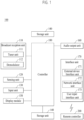
FIG. 1 is a block diagram illustrating constituent elements of a display device according to an embodiment of the present disclosure. -
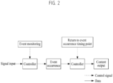
FIG. 2 is a diagram illustrating an operation of a display device according to an embodiment of the present disclosure. -
FIG. 3 is a diagram illustrating an embodiment of detecting noise by a display device according to an embodiment of the present disclosure. -
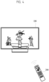
FIG. 4 is a diagram illustrating an embodiment of detecting noise by a display device according to another embodiment of the present disclosure. -
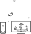
FIG. 5 is a diagram illustrating an embodiment of detecting an event by a display device according to an embodiment of the present disclosure. -
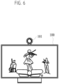
FIG. 6 is a diagram illustrating an embodiment of detecting an event by a display device according to an embodiment of the present disclosure. -
FIG. 7 is a diagram illustrating an embodiment of outputting an event occurrence list by a display device according to an embodiment of the present disclosure. -
FIG. 8 is a flowchart illustrating a method of controlling a display device according to an embodiment of the present disclosure. - Description will now be given in detail according to exemplary embodiments disclosed herein, with reference to the accompanying drawings. For the sake of brief description with reference to the drawings, the same or equivalent components may be provided with the same reference numbers, and description thereof will not be repeated. In general, a suffix such as "module" and "unit" may be used to refer to elements or components. Use of such a suffix herein is merely intended to facilitate description of the specification, and the suffix itself is not intended to give any special meaning or function. In the present disclosure, that which is well-known to one of ordinary skill in the relevant art has generally been omitted for the sake of brevity. The accompanying drawings are used to help easily understand various technical features and it should be understood that the embodiments presented herein are not limited by the accompanying drawings. As such, the present disclosure should be construed to extend to any alterations, equivalents and substitutes in addition to those which are particularly set out in the accompanying drawings.
- It will be understood that although the terms first, second, etc. may be used herein to describe various elements, these elements should not be limited by these terms. These terms are generally only used to distinguish one element from another.
- It will be understood that when an element is referred to as being "connected with" another element, the element can be directly connected with the other element or intervening elements may also be present. In contrast, when an element is referred to as being "directly connected with" another element, there are no intervening elements present.
- A singular representation may include a plural representation unless it represents a definitely different meaning from the context.
- Terms such as "include" or "has" are used herein and should be understood that they are intended to indicate an existence of several components, functions or steps, disclosed in the specification, and it is also understood that greater or fewer components, functions, or steps may likewise be utilized.
- On the other hand, the image display device described herein is, for example, an intelligent image display device implemented by adding a computer support function to a broadcast reception function, and further includes an Internet function or the like while sufficiently performing the broadcast reception function, so that the image display device may have user-friendly interfaces such as a handwriting input device, a touchscreen, or a spatial remote controller. Further, the image display device can support a wired or wireless Internet function by connecting to the Internet and a computer device, thereby performing e-mailing, web browsing, banking, or gaming. To implement these functions, the image display device may operate based on a standard general-purpose Operating System (OS).
- Accordingly, the image display device according to the present disclosure is designed in a manner that various applications can be easily added to or deleted from a general-purpose OS kernel so that the image display device can perform various user-friendly functions. The image display device may be, for example, a network TV, a Hybrid broadcast broadband TV (HBBTV), a smart TV, etc. The image display device is applicable to a smartphone as needed.
-
FIG. 1 is a block diagram illustrating constituent elements of adisplay device 100 according to an embodiment of the present disclosure. - Referring to
FIG. 1 , thedisplay device 100 may include abroadcast reception unit 110, an externaldevice interface unit 171, anetwork interface unit 172, astorage unit 140, a userinput interface unit 173, aninput unit 130, acontroller 180, adisplay 150, anaudio output unit 160, and/or a power-supply unit 190. - The
broadcast reception unit 110 may include atuner unit 111 and ademodulator 112. - Although not shown in the drawings, the
display device 100 may include only the externaldevice interface unit 171 and thenetwork interface unit 172 from among thebroadcast reception unit 110, the externaldevice interface unit 171, and thenetwork interface unit 172. That is, thedisplay device 100 may not include thebroadcast reception unit 110. - The
tuner unit 111 may select a broadcast signal corresponding to either a user-selected channel or all prestored channels from among broadcast signals received through an antenna (not shown) or a cable (not shown). Thetuner unit 111 may convert the selected broadcast signal into an intermediate frequency (IF) signal or a baseband image or a voice signal. - For example, when the selected broadcast signal is a digital broadcast signal, the
tuner unit 111 may convert the selected broadcast signal into a digital IF (DIF) signal. When the selected broadcast signal is an analog broadcast signal, thetuner unit 111 may convert the selected broadcast signal into an analog baseband image or a voice signal (CVBS/SIF). That is, thetuner unit 111 may process the digital broadcast signal or the analog broadcast signal. The analog baseband image or the voice signal (CVBS/SIF) output from thetuner unit 111 may be directly input to thecontroller 180. - The
tuner unit 111 may sequentially select broadcasting signals of all broadcasting channels stored through a channel memory function from among the received broadcast signals, and may convert the selected broadcast signal into an intermediate frequency (IF) signal or a baseband image or a voice signal. - The
tuner unit 111 may include a plurality of tuners to receive broadcast signals of the plurality of channels. Alternatively, a single tuner for simultaneously receiving broadcast signals of the plurality of channels is also possible. - The
demodulator 112 may receive the digital IF signal (DIF) converted by thetuner unit 111, and may thus perform demodulation of the received signal. Thedemodulator 112 may perform demodulation and channel decoding, and may output a stream signal (TS). The stream signal may be a signal formed by multiplexing an image signal, a voice signal, or a data signal. - The stream signal (TS) output from the
demodulator 112 may be input tio thecontroller 180. Thecontroller 180 may perform demultiplexing, image/audio signal processing, etc., may output an image through thedisplay 150, and may output a voice through theaudio output unit 160. - The
sensing unit 120 may sense a change in thedisplay device 100 or may sense an external change. For example, thesensing unit 120 may include a proximity sensor, an illumination sensor, a touch sensor, an infrared (IR) sensor, an ultrasonic sensor, an optical sensor (e.g., a camera), a voice sensor (e.g., a microphone), a battery gauge, environmental sensors (e.g., hygrometer, a thermometer, etc.). - The
controller 180 may check a state of thedisplay device 100 based on information collected by thesensing unit 120, may notify the user of a problem, or may control thedisplay device 100 to be kept in the best state. - In addition, it is possible to provide an optimal viewing environment by differently controlling the content, image quality, size, etc. of the image provided to the
display module 180 depending on the viewer, ambient illuminance, etc. sensed by the sensing unit. As the smart TV has evolved, the number of functions mounted in the display device increases, and the number of the sensing units 20 also increases together with the increasing functions. - The
input unit 130 may be provided at one side of a main body of thedisplay device 100. For example, theinput unit 130 may include a touch pad, a physical button, and the like. Theinput unit 130 may receive various user commands related to the operation of thedisplay device 100, and may transmit a control signal corresponding to the input command to thecontroller 180. - Recently, as a bezel of the
display device 100 decreases in size, the number ofdisplay devices 100 each including a minimum number ofinput unit 130 formed in a physical button exposed to the outside is rapidly increasing. Instead, a minimum number of physical buttons may be provided on the back or side surface of thedisplay device 100. The display device may receive a user input through theremote controller 200 through a touchpad or a userinput interface unit 173 to be described later. - The
storage unit 140 may store a program for processing and controlling each signal used in thecontroller 180, and may store a signal-processed image, a voice, or a data signal. For example, thestorage unit 140 may store application programs designed for the purpose of performing various tasks that can be processed by thecontroller 180, and may selectively provide some of the stored application programs upon request of thecontroller 180. - The program stored in the
storage unit 140 is not specifically limited to being executed by thecontroller 180. Thestorage unit 140 may perform a function for temporarily storing an image, a voice, or a data signal received from an external device through the externaldevice interface unit 171. Thestorage unit 140 may store information about a predetermined broadcast channel through a channel memory function such as a channel map. - Although the
storage unit 140 ofFIG. 1 is provided separately from thecontroller 180, the scope of the present disclosure is not limited thereto, and thestorage unit 140 may also be included in thecontroller 180 as needed. - The
storage unit 140 may include at least one of a volatile memory (e.g., DRAM, SRAM, SDRAM, etc.) and a non-volatile memory (e.g., flash memory, hard disk drive (HDD), solid state drive (SSD), etc.). - The
display 150 may generate a drive signal by converting an image signal, a data signal, an OSD signal, a control signal processed by thecontroller 180, or by converting an image signal, a data signal, a control signal, etc. received from theinterface unit 171. Thedisplay 150 may include a display panel 181 having a plurality of pixels. - A plurality of pixels included in the display panel may include RGB sub-pixels. Alternatively, a plurality of pixels included in the display panel may include sub-pixels of RGBW. The
display 150 may convert the image signal, the data signal, the OSD signal, the control signal, etc. processed by thecontroller 180 to generate a drive signal for the plurality of pixels. - The
display 150 may be implemented as a plasma display panel (PDP), a liquid crystal display (LCD), an organic light emitting diode (OLED), a flexible display, etc. In addition, thedisplay 150 may also be implemented as a three-dimensional (3D) display. The three-dimensional (3D)display 150 may be classified into a glassless-type 3D display and a glasses-type 3D display. - The display device may include a display module that occupies most parts of the front surface, and a case that covers the back and side surfaces of the display module and packages the display module.
- Recently, the
display device 100 has evolved from a flat-screen display to a curved-screen display. In order to implement the curved screen, thedisplay device 100 may use adisplay module 150 that can be bent or curved, such as a light emitting diode (LED) or an organic light emitting diode (OLED), etc. - Conventionally, the LCD has difficulty in self-emitting light, so that the conventional LCD has been designed to receive light through a backlight unit. The backlight unit is a device for uniformly supplying light received from a light source to a liquid crystal located on the front surface of the display device. As the backlight becomes thinner, a thin LCD can be implemented. However, it is actually difficult for the backlight unit to be implemented as a curved structure formed of a flexible material. Although the backlight unit is implemented as a curved shape, it is difficult for light to be uniformly applied to the liquid crystal, thereby changing brightness of the screen.
- On the other hand, the LED or the OLED is designed in a manner that each of constituent elements constructing the pixels can self-emit light without using the backlight unit, so that the LED or the OLED can be implemented as a curved shape without any problems. In addition, since each element can perform self-emission of light, brightness of each element is not affected by a change in the positional relationship between the element and adjacent elements, so that a
curved display module 150 can be implemented as an LED or OLED. - OLED (Organic Light Emitting Diode) panels appeared in earnest in mid-2010 and are rapidly replacing LCDs in the small- and medium-sized display market. The OLED is a display made using the self-emission characteristics in which OLED emits light when a current flows in a fluorescent organic compound. Since the response speed of the OLED is faster than that of the LCD, there is little afterimage when moving images are implemented.
- OLEDs may be used as a light-emitting display product. In this case, the light-emitting display device may use three fluorescent organic compounds (such as red, green, and blue) each having a self-emitting function, and may use the self-emitting phenomenon in which positive(+)-charged particles and electrons injected from a cathode and anode are combined with each other within the organic material, so that a backlight unit causing degradation of color sense need not be used.
- The LED panel is implemented by technology for using only one LED element as one pixel, and has a smaller LED element compared to the prior art, so that a
curved display module 150 can be implemented. Whereas the conventional device referred to as an LED TV can use the LED as a light source of the backlight unit for supplying light to the LCD, it is impossible for the LED of the conventional device to constitute a screen. - The display module may include a display panel, a coupling magnet located on the rear surface of the display panel, a first power-supply unit, and a first signal module. The display panel may include a plurality of pixels (R, G, B). The plurality of pixels (R, G, B) may be formed in each region where a plurality of data lines and a plurality of gate lines cross each other. The plurality of pixels (R, G, B) may be arranged in a matrix.
- For example, the plurality of pixels (R, G, B) may include a red(R) sub-pixel, a green(G) sub-pixel, and a blue(B) sub-pixel. The plurality of pixels (R, G, B) may further include white (W) sub-pixel(s).
- In the
display module 150, one side where an image is displayed may be referred to as a front side or a front surface. When thedisplay module 150 displays an image, one side where no image is observed may be referred to as a rear side or a rear surface. - Meanwhile, the
display 150 may be implemented as a touchscreen, so that thedisplay 150 can also be used as an input device in addition to an output device. - The
audio output unit 160 may receive a voice-processed signal from thecontroller 180, and may output the received signal as a voice signal. - The
interface unit 170 may serve as a path of connection to various kinds of external devices connected to thedisplay device 100. The interface unit may include not only a wired method for transmitting/receiving data through a cable, but also a wireless method using the antenna. - The
interface unit 170 may include at least one of a wired/wireless headset port, an external charger port, a wired/wireless data port, a memory card port, a port connected to a device having an identification module, an audio input/output (I/O) port, a video I/O port, and an earphone port. - As an example of a wireless method, the above-described
broadcast reception unit 110 may be used. Thebroadcast reception unit 110 may be configured to use a broadcast signal, a mobile communication short-range communication signal, a wireless Internet signal, and the like. - The external
device interface unit 171 may transmit or receive data to and from a connected external device. To this end, the externaldevice interface unit 171 may include an A/V input/output (I/O) unit (not shown). - The external
device interface unit 171 may be wired or wirelessly connected to an external device such as a digital versatile disc (DVD) player, a Blu-ray player, a game console, a camera, a camcorder, a computer (laptop), a set-top box, or the like, and may perform an input/output (I/O) operation with the external device. - In addition, the external
device interface unit 171 may establish a communication network with variousremote controllers 200, may receive a control signal related to operation of thedisplay device 100 from theremote controller 200, or may transmit data related to operation of thedisplay device 100 to theremote controller 200. - The external
device interface unit 171 may include a wireless communication unit (not shown) for short-range wireless communication with other electronic devices. Through the wireless communication unit (not shown), the externaldevice interface unit 171 may exchange data with an adjacent mobile terminal. In particular, the externaldevice interface unit 171 may receive device information, application information, an application image, and the like from the mobile terminal in a mirroring mode. - The
network interface unit 172 may provide an interface for connecting thedisplay device 100 to a wired/wireless network including the Internet network. For example, thenetwork interface unit 172 may receive content or data provided by the Internet, a content provider, or a network administrator through a network. Thenetwork interface unit 172 may include a communication module (not shown) for connection with the wired/wireless network. - The external
device interface unit 171 and/or thenetwork interface unit 172 may include a communication module for short-range communication such as Wi-Fi, Bluetooth, Bluetooth low energy (BLE), ZigBee, Near Field Communication (NFC), and a communication module for cellular communication such as Long-Term Evolution (LTE), LTE-A (LTE Advanced), Code Division Multiple Access (CDMA), WCDMA(wideband CDMA), UMTS(universal mobile telecommunications system), WiBro(Wireless Broadband), etc. - The user
input interface unit 173 may transmit user input signals to thecontroller 180, or may transmit signals received from thecontroller 180 to the user. For example, the userinput interface unit 173 may transmit or receive user input signals (such as a power-on/off signal, a channel selection signal, and a screen setting signal) to and from theremote controller 200, may transmit user input signals received through a local key (not shown) such as a power key, a channel key, a volume key, and a setting key to thecontroller 180, may transmit a user input signal received by a sensor unit (not shown) for sensing a user gesture to thecontroller 180, or may transmit a signal received from thecontroller 180 to the sensor unit. - The
controller 180 may include at least one processor, and may control the overall operation of thedisplay device 100 using the processor included therein. Here, the processor may be a general processor such as a CPU. Of course, the processor may be a dedicated device such as an ASIC, or other hardware-based processor. - The
controller 180 may demultiplex the stream received through thetuner unit 111, thedemodulator 112, the externaldevice interface unit 171, or thenetwork interface 172, and may process the demultiplexed signals to generate and output a signal for image or voice output. - The image signal processed by the
controller 180 may be input to thedisplay 150 and displayed as an image corresponding to the corresponding image signal. In addition, the image signal processed by thecontroller 180 may be input to the external output device through the externaldevice interface unit 171. - The voice (or audio) signal processed by the
controller 180 may be audibly output to theaudio output unit 160. In addition, the voice signal processed by thecontroller 180 may be input to the external output device through the externaldevice interface unit 171. Although not shown inFIG. 2 , thecontroller 180 may include a demultiplexer, an image processor, and the like, and a detailed description thereof will hereinafter be described with reference toFIG. 3 . - In addition, the
controller 180 may control the overall operation of thedisplay device 100. For example, thecontroller 180 may control thetuner unit 111 to select a broadcast program corresponding to either a user-selected channel or a prestored channel. - In addition, the
controller 180 may control thedisplay device 100 by a user command or an internal program received through the userinput interface unit 173. Thecontroller 180 may control thedisplay 150 to display an image. In this case, the image displayed on thedisplay 150 may be a still image or a moving image, and may be a 2D image or a 3D image. - On the other hand, the
controller 180 may display a predetermined 2D object in the image displayed on thedisplay 150. For example, the object may be at least one of a connected web screen (newspaper, magazine, etc.), electronic program guide (EPG), various menus, widgets, icons, still images, moving images, and text. - Meanwhile, the
controller 180 may modulate and/or demodulate the signal using an amplitude shift keying (ASK) scheme. Here, the ASK scheme may refer to a method for modulating a signal by differentiating the amplitude of a carrier wave according to data values or for restoring an analog signal to a digital data value according to the amplitude of the carrier wave. - For example, the
controller 180 may modulate an image signal using the ASK scheme, and may transmit the modulated signal through a wireless communication module. - For example, the
controller 180 may demodulate and process the image signal received through the wireless communication module using the ASK scheme. - Accordingly, the
display device 100 may simply transmit and receive signals to and from other image display devices arranged adjacent to each other without using either a unique identifier such as a Media Access Control (MAC) address or a complex communication protocol such as TCP/IP. - On the other hand, the
display device 100 may further include a photographing unit (not shown). The photographing unit may photograph a user. The photographing unit may be implemented as one camera, but is not limited thereto, and may be implemented by a plurality of cameras. On the other hand, the photographing unit may be embedded in thedisplay device 100 or may be separately arranged on thedisplay 150. The image information photographed by the photographing unit may be input to thecontroller 180. - The
controller 180 may recognize the position of the user based on the image photographed by the photographing unit. For example, thecontroller 180 may recognize a distance (z-axis coordinates) between the user and thedisplay device 100. In addition, thecontroller 180 may recognize the X-axis coordinate and the Y-axis coordinate within thedisplay 150 corresponding to the user position. - The
controller 180 may sense a user gesture based on an image photographed by the photographing unit, each of signals detected by the sensor unit, or a combination thereof. - The power-supply unit 190 may supply corresponding power to the
display device 100. In particular, thecontroller 180 may be implemented as a System on Chip (SoC), adisplay 150 for displaying an image, and anaudio output unit 160 for audio output. - Specifically, the power-supply unit 190 may include a converter (not shown) for converting AC power into DC power, and a DC/DC converter (not shown) for converting the level of DC power.
- On the other hand, the power-supply unit 190 may receive power from the external power source, and may distribute the received power to the respective components. The power-supply unit 190 may be directly connected to the external power source to supply AC power, and may include a battery capable of being charged with electricity.
- In the former case, the power-supply unit 190 may be used by connecting to a wired cable, and it is difficult for the power-supply unit 190 to move from one place to another place, and the movement range of the power-supply unit 190 is limited. In the latter case, the power-supply unit 190 can move from one place to another place, but the weight and volume of the power-supply unit 190 may increase as much as the weight and volume of the battery. In addition, for charging, the power-supply unit 190 should be directly connected to a power cable for a predetermined period of time or should be coupled to a charging cradle (not shown) for power supply.
- The charging cradle may be connected to the display device through a terminal exposed to the outside. Alternatively, if the power-supply unit 190 approaches the charging cradle using a wireless interface, a built-in battery of the power-supply unit 190 may also be charged with electricity.
- The
remote controller 200 may transmit a user input to the userinput interface unit 173. To this end, theremote controller 200 may use Bluetooth, Radio Frequency (RF) communication, infrared (IR) communication, Ultra-Wideband (UWB), ZigBee, or the like. In addition, theremote controller 200 may receive the image, voice, or data signal output from the userinput interface unit 173, and may display or audibly output the received image, voice, or data signal. - On the other hand, the above-described
display device 100 may be a fixed or mobile digital broadcast receiver capable of receiving digital broadcast signals. - Meanwhile, the block diagram of the
display device 100 shown inFIG. 1 is disclosed for only for illustrative purposes for one embodiment of the present disclosure, and the respective components of thedisplay device 100 shown inFIG. 1 can be integrated, added or omitted according to the specifications of thedigital device 100 which is actually implemented. - That is, if necessary, two or more components may be combined into one component, or one component may be subdivided into two or more components. In addition, the functions performed in each block are intended to explain the embodiment of the present disclosure, and the specific operation or device does not limit the scope of the present disclosure.
- The time shift technology of the related art generally performs recording and playback constantly over time. However, in this case, when there is a problem with watching TV due to external noise (such as phone calls, conversations, external noise such as the sound of an airplane, etc.), it is cumbersome to return to a corresponding interval.
- In particular, since it is difficult to accurately find the time and interval (10 seconds, 30 seconds, 1 minute, etc.) that was missed, it is intended to propose a method of storing a time and interval where noise occurred and playing it again.
-
FIG. 2 is a diagram illustrating an operation of a display device according to an embodiment of the present disclosure. Hereinafter, a description redundant with the foregoing description will be omitted. - Referring to
FIG. 2 , a controller (hereinafter, an operation performed by the controller will be described as performed by a display device for convenience of description) may receive a signal input. That is, the display device may receive data from the outside in order to output a content. In this case, the display device may receive to output a broadcast content through a broadcast reception unit or may receive to output a content through an interface unit. In this case, when an event occurs while the broadcast content received through the broadcast reception unit is being outputted, the display device may need to store the broadcast content itself. This corresponds to a case in which the broadcast content received through the broadcast reception unit does not provide a replay function. This will be described in detail with reference toFIG. 8 . - According to an embodiment, the display device may constantly monitor an event. This may be turned on/off through a setting menu. According to an embodiment, the display device may detect an event occurrence in a state in which a content is being outputted. In this case, the display device may store a timing point at which the event has occurred. For example, the display device may record the event occurrence at the timing point of 22:04 of a first content in a memory. Hereinafter, an embodiment in which the display device detects an event occurrence will be described in detail with reference to
FIGS. 3 to 6 . - Thereafter, the display device may return to the event occurrence timing point based on a control signal. In an embodiment, the display device may return to a most recently occurring event timing point based on the control signal. In more detail, when the most recently occurring event timing point is 17:45 of a second content, the display device may directly play the 17:45 of the second content based on the control signal. Accordingly, a user may directly play the content that has not been viewed due to sudden noise.
- On the other hand, in another embodiment, the display device may output an event occurrence list, select a first event from the event occurrence list, and then output a content. This will be described in detail with reference to
FIG. 7 . - A display device according to an embodiment of the present disclosure may distinguish a sound of an outputted content and a noise generated from the outside from each other. This is because an output waveform of the sound of the content outputted from the display device is known. Accordingly, the display device may distinguish a noise received from an external device, a noise received from a microphone included in the display device itself, and an audio output generated from a content.
- That is, irrespective of a volume of a content being outputted from the display device, the display device may determine a sound of a first decibel or higher as a noise other than an output sound of the content.
- This will be described in detail through the following drawings.
-
FIG. 3 is a diagram illustrating an embodiment in which a display device detects noise according to an embodiment of the present disclosure. Hereinafter, a description redundant with the foregoing description redundant with the foregoing description will be omitted. - Referring to
FIG. 3 , adisplay device 100 may detect noise through anAI speaker 300 while outputting a content. - Here, the noise is characterized in having a first decibel (dB) or higher. In addition, the first decibel may be determined when a manufacturer delivers the
display device 100 or may be determined by a user setting. - In addition, the
display device 100 and theAI speaker 300 may use the same Wi-Fi through a wireless router or the like. Accordingly, thedisplay device 100 may detect noise through theAI speaker 300. - When the
display device 100 detects noise, thedisplay device 100 may record a noise occurrence timing point of the content being outputted. For example, when thedisplay device 100 receives a noise occurrence from theAI speaker 300 at a play timing point 26:33 of the content, thedisplay device 100 may record the timing point 26:33 of the content. Thereafter, thedisplay device 100 may play the timing point 26:33 of the content based on a control signal for directly moving to the noise occurrence timing point or a control signal for outputting an event occurrence list. - Through this, when external noise above a specific decibel (dB) occurs, a trigger of that moment is stored to easily return thereto.
-
FIG. 4 is a diagram illustrating an embodiment in which a display device detects noise according to another embodiment of the present disclosure. Hereinafter, a description redundant with the foregoing description will be omitted. - In an embodiment of the present disclosure, an external device is a
remote controller 200 including a microphone. That is, theremote controller 200 recently commercialized may include a microphone to provide voice recognition. In this case, in an embodiment, adisplay device 100 may detect noise using the microphone in theremote controller 200. In this case, theremote controller 200 and thedisplay device 100 may transceive information with each other using Wi-Fi, Bluetooth, or the like. - Referring to
FIG. 4 , thedisplay device 100 may detect noise through the microphone. Thereafter, when the detected noise is greater than or equal to a first value, thedisplay device 100 may record a noise occurrence timing point of a content being outputted. - Thereafter, the
display device 100 may play the content at the noise occurrence timing point detected through the microphone based on a control signal for moving to the noise occurrence timing point. - Through this, when external noise greater than or equal to a specific decibel (dB) occurs, a trigger of that moment is stored to easily return thereto.
-
FIG. 5 is a diagram illustrating an embodiment in which a display device detects an event according to another embodiment of the present disclosure. Hereinafter, a description redundant with the foregoing description will be omitted. - In an embodiment of the present disclosure, an external device is characterized in being a
mobile terminal 400. Here, themobile terminal 400 is characterized in being a user device connected to thedisplay device 100 through the same Wi-Fi or the like. Also, inFIG. 5 , onemobile terminal 400 is connected to thedisplay device 100, but of course, a plurality ofmobile terminals 400 may be connected to thedisplay device 100. In this case, thedisplay device 100 may manage a plurality of the mobile terminals by giving an ID of the mobile terminal. - Referring to
FIG. 5 , when themobile terminal 400 is in use, thedisplay device 100 may record an event occurrence timing point of a content being outputted. - More specifically, a user often uses the
mobile terminal 400 while viewing a content being outputted from thedisplay device 100. For example, a phone call or a text is received by themobile terminal 400, or a user surfs the web. - That is, although the content is being played in the
display device 100, the user cannot fully concentrate on the content being played because the user uses themobile terminal 400. In this case, thedisplay device 100 may record the case in which themobile terminal 400 is in use as an event occurrence timing point and play it again as receiving a control signal later. - When a call is transmitted or received by the
mobile terminal 400, thedisplay device 100 may receive information, which indicates that the call is transmitted or received, from themobile terminal 400. Accordingly, thedisplay device 100 may record a content time of the timing point at which the call starts. - Also, when a user starts to touch the
mobile terminal 400, thedisplay device 100 may receive touch information from themobile terminal 400. Thus, thedisplay device 100 may record a content time of the timing point when the user uses themobile terminal 400. - In another embodiment, only when a user inputs a touch signal to the
mobile terminal 400 and then inputs a touch signal again even after elapse of a first time, thedisplay device 100 may determine it as an event occurrence. That is, when the user activates themobile terminal 400 simply to view a clock, thedisplay device 100 may not determine it as an event occurrence. However, when the user operates themobile terminal 400 for a first time (e.g., 5 minutes) or more, thedisplay device 100 may determine that the user fails to concentrate on a content being outputted and record an event occurrence timing point. - Thereafter, the
display device 100 may play a content corresponding to the event occurrence timing point based on a control signal for returning to the event occurrence timing point. -
FIG. 6 is a diagram illustrating an embodiment in which a display device detects an event according to an embodiment of the present disclosure. Hereinafter, a description redundant with the foregoing description will be omitted. - Referring to
FIG. 6 , adisplay device 100 may further include acamera 101. Here, thecamera 101 may be attached to a front surface of thedisplay device 100 to capture an image or video. - The
display device 100 may detect a user through thecamera 101. In an embodiment of the present disclosure, thedisplay device 100 may determine a case in which the user is not detected through thecamera 101 as an event occurrence. - That is, in various cases, the user leaves a seat while watching a content that is being outputted from the
display device 100. In this case, thedisplay device 100 may detect a state in which the user has left the seat, and determine the state in which the user has left the seat as an event occurrence. Accordingly, thedisplay device 100 may record a timing point at which the user has left the seat as an event occurrence timing point. - In addition, when the state in which the user has left the seat continues for a first time (e.g., 10 minutes) or more, the
display device 100 may determine it as an event occurrence. That is, the user may go to the bathroom while viewing a content through thedisplay device 100. In this case, when the viewed content is not paused or cannot be paused, the user misses a part of the content. To compensate for this, when the state in which the user has left the seat continues for the first time or more, thedisplay device 100 may determine it as an event occurrence and record a first timing point of the content, which is an event occurrence timing point. - Thereafter, the
display device 100 may play the content corresponding to the event occurrence timing point based on a control signal for returning to the event occurrence timing point. -
FIG. 7 is a diagram illustrating an embodiment in which a display device outputs an event occurrence list, according to an embodiment of the present disclosure. Hereinafter, a description redundant with the foregoing description will be omitted. - Referring to
FIG. 7 (a) , adisplay device 100 may receive a first control signal for outputting an event occurrence list. Here, the first control signal may correspond to a signal for selecting a physical button (e.g., an event occurrence list output button) included in aremote controller 200 or a control signal for selecting an icon (not shown) in thedisplay device 100. - More specifically, in response to receiving the first control signal, the
display device 100 may output anevent occurrence list 700. Here, the event occurrence list may include a first timing point and a first content information that is being outputted. - In particular, the event occurrence list may include an event occurrence timing point recorded by the
display device 100 according to the above-described embodiment. For example, thedisplay device 100 may record that a phone call is made from Harry's phone (a mobile terminal registered in the display device 100) at 14:22 on May 10, 2022. In addition, thedisplay device 100 may include 'the content viewed at this timing point that is the content-A of Netflix and is the first timing point' in the event occurrence list. - That is, the event occurrence list may include at least one event occurrence timing point and content information at the event occurrence timing point.
- Referring to
FIG. 7 (b) , thedisplay device 100 may play a first timing point of acontent 710 based on a second control signal for selecting afirst event 701 included in the event occurrence list. Here, like the first signal, the second signal may correspond to a signal for selecting a physical button (e.g., a play button) included in theremote controller 200 or a control signal for selecting an icon (not shown) in thedisplay device 100. - More specifically, a user may select the
first event 701 from the event occurrence list. Here, thefirst event 701 may be, for example, an event that occurred at 18:30 on May 11, 2022, and may be characterized in being noise detected through an AI speaker among external devices. For example, when the noise occurs, the user may be watching a first timing point 22: 10 of thecontent 710 of a KBS1 channel through thedisplay device 100. Accordingly, thedisplay device 100 may play the first timing point of thecontent 710 based on the second control signal for selecting thefirst event 701. -
FIG. 8 is a flowchart illustrating a method of controlling a display device according to an embodiment of the present disclosure. Hereinafter, a description redundant with the foregoing description will be omitted. - In a step S810, a display device may be power on or turned on. Thereafter, the display device may start event monitoring. According to an embodiment, the display device may set whether to always monitor an event. For example, a user may set whether to always turn on/off an event detection through a setting menu of the display device.
- In a step S820, the display device may detect a first event occurrence while a first content is being outputted. Here, the display device may detect noise through an external device (such as an AI speaker, a remote controller including a microphone, etc.). In addition, the display device may determine a case in which an external device is in use as a case in which an event occurs. In addition, the display device may determine a case in which a user is not detected through a camera as a case in which an event occurs.
- In an embodiment, when the first content is a content received through a broadcast reception unit, the display device may store the content in a memory as a first event is detected.
- More specifically, the display device may output a content through a display. In this case, the outputted content may correspond to a content received through the broadcast reception unit or a content received through an interface unit.
- In the case of the content received through the interface unit, the display device may play the content again from a first timing point through the interface unit in order to play the content. On the other hand, in the case of the content received through the broadcast reception unit, the display device must store the content in a memory in order to play the content. This is because the content received through the broadcast reception unit is not provided with a replay function unlike a content provided by a general OTT platform.
- To this end, in an embodiment of the present disclosure, when a content being outputted is a content received through the broadcast reception unit, the display device may store the content in the memory in response to detecting an event occurrence. Here, the memory may include a general hard disk, an SSD disk, a USB drive, or the like.
- In a step S830, the display device may store a first timing point at which the first event is detected. The steps S820 and S830 will be described with reference to the foregoing descriptions of
FIGS. 3 to 6 . - In a step S840, the display device may receive a first control signal. In an embodiment, it is characterized in that the first control signal is a physical button included in a remote controller. That is, the remote controller according to an embodiment of the present disclosure is characterized in including a physical button for outputting an event occurrence list.
- In a step S850, the display device may output an event occurrence list in response to receiving the first control signal. Here, the event occurrence list may include the first timing point at which the event occurs and the content information.
- In a step S860, the display device may play the first timing point of the first content based on a second control signal for selecting the first event included in the event occurrence list. The steps S840 to S860 will be described with reference to the foregoing description of
FIG. 7 . - The present disclosure may be implemented as code that can be written to a computer-readable recording medium and can thus be read by a computer. The computer-readable recording medium may be any type of recording device in which data can be stored in a computer-readable manner. Examples of the computer-readable recording medium include a hard disk drive (HDD), a solid state drive (SSD), a silicon disk drive (SDD), a ROM, a RAM, a CD-ROM, a magnetic tape, a floppy disk, optical data storage, and a carrier wave (e.g., data transmission over the Internet). In addition, the computer may include the controller. The above exemplary embodiments are therefore to be construed in all aspects as illustrative and not restrictive. The scope of the present disclosure should be determined by the appended claims and their legal equivalents, not by the above description, and all changes coming within the meaning and equivalency range of the appended claims are intended to be embraced therein.
- Since a display device and method of controlling the same according to an embodiment of the present disclosure may be repeatedly implemented, there is industrial applicability.
Claims (11)
- A display device, comprising:a memory;an interface unit communicating with an external device;a display outputting a content; anda controller configured to control the communication unit and the display,wherein the controller is further configured to detect an occurrence of an event in a state of outputting the content, store a timing point of detecting the event, output an event occurrence list in response to receiving a first control signal, and play a first timing point of a first content based on a second control signal for selecting a first event included in the event occurrence list.
- The display device of claim 1, wherein the event is a noise greater than or equal to a first decibel.
- The display device of claim 2, wherein the external device is an AI speaker and wherein the controller detects the noise through the AI speaker.
- The display device of claim 2, wherein the external device is a remote controller including a microphone and wherein the controller detects the noise through the microphone.
- The display device of claim 2, wherein the external device is a mobile terminal and wherein the event includes a case that the mobile terminal is in use.
- The display device of claim 1, further comprising a camera, wherein the event includes a case that a user is not detected through the camera.
- The display device of claim 1, wherein the event occurrence includes the first timing point and the first content information.
- The display device of claim 1, wherein based on receiving a third control signal, the controller plays a second timing point of a content related to a most recently occurring event.
- The display device of claim 1, wherein the first control signal is a signal for selecting a physical button included in a remote controller.
- The display device of claim 1, wherein based on the content being a content received through a broadcast reception unit, the controller stores the content in the memory in response detecting the event.
- A method of controlling a display device, the method comprising:detecting an event in a state that a content is being outputted,storing a timing point of detecting the event;outputting an event occurrence list in response to receiving a first control signal; andplaying a first timing point of a first content based on a second control signal for selecting a first event included in the event occurrence list.
Applications Claiming Priority (1)
| Application Number | Priority Date | Filing Date | Title |
|---|---|---|---|
| PCT/KR2022/008527 WO2023243746A1 (en) | 2022-06-16 | 2022-06-16 | Display device and display device control method |
Publications (2)
| Publication Number | Publication Date |
|---|---|
| EP4539478A1 true EP4539478A1 (en) | 2025-04-16 |
| EP4539478A4 EP4539478A4 (en) | 2025-04-30 |
Family
ID=89191520
Family Applications (1)
| Application Number | Title | Priority Date | Filing Date |
|---|---|---|---|
| EP22946952.3A Pending EP4539478A4 (en) | 2022-06-16 | 2022-06-16 | Display device and display device control method |
Country Status (4)
| Country | Link |
|---|---|
| US (1) | US20250373902A1 (en) |
| EP (1) | EP4539478A4 (en) |
| KR (1) | KR20250016171A (en) |
| WO (1) | WO2023243746A1 (en) |
Family Cites Families (11)
| Publication number | Priority date | Publication date | Assignee | Title |
|---|---|---|---|---|
| KR100720575B1 (en) | 2004-12-14 | 2007-05-22 | 엘지전자 주식회사 | Television set and control method for switching from voice mode to text mode according to ambient noise |
| KR100792399B1 (en) * | 2006-05-09 | 2008-01-09 | 동원대학 산학협력단 | Noise prevention device and method of image display device |
| KR20080017692A (en) * | 2006-08-22 | 2008-02-27 | 엘지전자 주식회사 | Broadcast data playback method and device |
| US9165144B1 (en) * | 2012-12-19 | 2015-10-20 | Audible, Inc. | Detecting a person who does not satisfy a threshold age within a predetermined area |
| US9274673B2 (en) * | 2013-12-31 | 2016-03-01 | Google Inc. | Methods, systems, and media for rewinding media content based on detected audio events |
| US9800938B2 (en) * | 2015-01-07 | 2017-10-24 | Echostar Technologies L.L.C. | Distraction bookmarks for live and recorded video |
| KR101925034B1 (en) * | 2017-03-28 | 2018-12-04 | 엘지전자 주식회사 | Smart controlling device and method for controlling the same |
| KR102831245B1 (en) * | 2018-10-23 | 2025-07-08 | 삼성전자주식회사 | Electronic device and method for controlling electronic device |
| KR102139331B1 (en) * | 2018-11-20 | 2020-07-29 | 주식회사 엘지유플러스 | Apparatus, server, and method for playing moving picture contents |
| KR102741200B1 (en) * | 2019-07-30 | 2024-12-10 | 엘지전자 주식회사 | Smart lighting and method for operating the same |
| US11722731B2 (en) * | 2020-11-24 | 2023-08-08 | Google Llc | Integrating short-term context for content playback adaption |
-
2022
- 2022-06-16 US US18/871,776 patent/US20250373902A1/en active Pending
- 2022-06-16 EP EP22946952.3A patent/EP4539478A4/en active Pending
- 2022-06-16 WO PCT/KR2022/008527 patent/WO2023243746A1/en not_active Ceased
- 2022-06-16 KR KR1020247041086A patent/KR20250016171A/en active Pending
Also Published As
| Publication number | Publication date |
|---|---|
| US20250373902A1 (en) | 2025-12-04 |
| WO2023243746A1 (en) | 2023-12-21 |
| EP4539478A4 (en) | 2025-04-30 |
| KR20250016171A (en) | 2025-02-03 |
Similar Documents
| Publication | Publication Date | Title |
|---|---|---|
| US12100327B2 (en) | Display device and method for controlling the same | |
| EP4213136A1 (en) | Display device and method for controlling the same | |
| EP4539478A1 (en) | Display device and display device control method | |
| US20250094014A1 (en) | Display device and control method thereof | |
| US20250358468A1 (en) | Display device, method for controlling display device, and method for controlling remote control device | |
| US20250330519A1 (en) | Miracast provision method and miracast provision system | |
| US20250185189A1 (en) | Display device | |
| US20260046467A1 (en) | Portable tv and method for controlling portable tv | |
| US12483741B2 (en) | Portable display device and control method for the same | |
| US12471158B2 (en) | Remote controller and system for controlling display device | |
| KR102767343B1 (en) | Movable tv and controlling method of the movable tv | |
| US20260046480A1 (en) | Tv and tv control method | |
| KR102722280B1 (en) | Display device and method thereof | |
| US12289596B2 (en) | Bendable display device and method for controlling the same | |
| EP4521758A1 (en) | Display device and control method thereof | |
| US20260101080A1 (en) | Tv, and method for controlling tv | |
| US12058507B2 (en) | Sound output equipment and display device | |
| KR20260029766A (en) | Method and system for remote control navigation based on remote control posture | |
| KR20240025308A (en) | A controlling method of electronic device and the eletronic device | |
| KR20240025307A (en) | Tv and controlling method for the tv | |
| CN118803329A (en) | Portable display device and control method thereof | |
| KR20260000317A (en) | Wireless Data Transmitter, Disply Modue and Wireless Disply System including them | |
| KR20240016688A (en) | Movable display device and controlling method of the movable display device | |
| CN121889769A (en) | Display device and control method of display device |
Legal Events
| Date | Code | Title | Description |
|---|---|---|---|
| STAA | Information on the status of an ep patent application or granted ep patent |
Free format text: STATUS: THE INTERNATIONAL PUBLICATION HAS BEEN MADE |
|
| PUAI | Public reference made under article 153(3) epc to a published international application that has entered the european phase |
Free format text: ORIGINAL CODE: 0009012 |
|
| STAA | Information on the status of an ep patent application or granted ep patent |
Free format text: STATUS: REQUEST FOR EXAMINATION WAS MADE |
|
| 17P | Request for examination filed |
Effective date: 20250108 |
|
| AK | Designated contracting states |
Kind code of ref document: A1 Designated state(s): AL AT BE BG CH CY CZ DE DK EE ES FI FR GB GR HR HU IE IS IT LI LT LU LV MC MK MT NL NO PL PT RO RS SE SI SK SM TR |
|
| A4 | Supplementary search report drawn up and despatched |
Effective date: 20250331 |
|
| RIC1 | Information provided on ipc code assigned before grant |
Ipc: H04N 21/488 20110101ALI20250325BHEP Ipc: H04N 21/442 20110101ALI20250325BHEP Ipc: H04N 21/4223 20110101ALI20250325BHEP Ipc: H04N 21/422 20110101ALI20250325BHEP Ipc: H04N 21/472 20110101AFI20250325BHEP |
|
| DAV | Request for validation of the european patent (deleted) | ||
| DAX | Request for extension of the european patent (deleted) |