EP4539357A2 - Satellite communication with modularized mobile earth stations (mess) - Google Patents
Satellite communication with modularized mobile earth stations (mess) Download PDFInfo
- Publication number
- EP4539357A2 EP4539357A2 EP25161104.2A EP25161104A EP4539357A2 EP 4539357 A2 EP4539357 A2 EP 4539357A2 EP 25161104 A EP25161104 A EP 25161104A EP 4539357 A2 EP4539357 A2 EP 4539357A2
- Authority
- EP
- European Patent Office
- Prior art keywords
- mess
- mes
- satellite
- auto
- signals
- Prior art date
- Legal status (The legal status is an assumption and is not a legal conclusion. Google has not performed a legal analysis and makes no representation as to the accuracy of the status listed.)
- Pending
Links
Images



Classifications
-
- H—ELECTRICITY
- H04—ELECTRIC COMMUNICATION TECHNIQUE
- H04B—TRANSMISSION
- H04B7/00—Radio transmission systems, i.e. using radiation field
- H04B7/14—Relay systems
- H04B7/15—Active relay systems
- H04B7/185—Space-based or airborne stations; Stations for satellite systems
- H04B7/1851—Systems using a satellite or space-based relay
-
- H—ELECTRICITY
- H04—ELECTRIC COMMUNICATION TECHNIQUE
- H04B—TRANSMISSION
- H04B7/00—Radio transmission systems, i.e. using radiation field
- H04B7/14—Relay systems
- H04B7/15—Active relay systems
- H04B7/185—Space-based or airborne stations; Stations for satellite systems
- H04B7/1851—Systems using a satellite or space-based relay
- H04B7/18519—Operations control, administration or maintenance
-
- H—ELECTRICITY
- H04—ELECTRIC COMMUNICATION TECHNIQUE
- H04B—TRANSMISSION
- H04B7/00—Radio transmission systems, i.e. using radiation field
- H04B7/14—Relay systems
- H04B7/15—Active relay systems
- H04B7/185—Space-based or airborne stations; Stations for satellite systems
- H04B7/1851—Systems using a satellite or space-based relay
- H04B7/18513—Transmission in a satellite or space-based system
-
- H—ELECTRICITY
- H04—ELECTRIC COMMUNICATION TECHNIQUE
- H04B—TRANSMISSION
- H04B7/00—Radio transmission systems, i.e. using radiation field
- H04B7/14—Relay systems
- H04B7/15—Active relay systems
- H04B7/185—Space-based or airborne stations; Stations for satellite systems
- H04B7/1851—Systems using a satellite or space-based relay
- H04B7/18517—Transmission equipment in earth stations
-
- H—ELECTRICITY
- H04—ELECTRIC COMMUNICATION TECHNIQUE
- H04B—TRANSMISSION
- H04B7/00—Radio transmission systems, i.e. using radiation field
- H04B7/14—Relay systems
- H04B7/15—Active relay systems
- H04B7/185—Space-based or airborne stations; Stations for satellite systems
- H04B7/18523—Satellite systems for providing broadcast service to terrestrial stations, i.e. broadcast satellite service
-
- H—ELECTRICITY
- H04—ELECTRIC COMMUNICATION TECHNIQUE
- H04B—TRANSMISSION
- H04B7/00—Radio transmission systems, i.e. using radiation field
- H04B7/14—Relay systems
- H04B7/15—Active relay systems
- H04B7/185—Space-based or airborne stations; Stations for satellite systems
- H04B7/1853—Satellite systems for providing telephony service to a mobile station, i.e. mobile satellite service
-
- H—ELECTRICITY
- H04—ELECTRIC COMMUNICATION TECHNIQUE
- H04B—TRANSMISSION
- H04B7/00—Radio transmission systems, i.e. using radiation field
- H04B7/14—Relay systems
- H04B7/15—Active relay systems
- H04B7/185—Space-based or airborne stations; Stations for satellite systems
- H04B7/18576—Satellite systems for providing narrowband data service to fixed or mobile stations, e.g. using a minisatellite, a microsatellite
Definitions
- This disclosure relates generally to satellite communications and more particularly to satellite communication with mobile earth stations (MESs).
- MESs mobile earth stations
- a mobile earth station is mobile wireless equipment capable of communicating (transmitting and/or receiving) signals to a satellite.
- An MES can be a hand-held portable wireless device, or a wireless device fixedly mounted to a mobile transporter such as a rail car of a train, a watercraft, a vehicle, or a robot.
- a plurality of MESs are mounted to different locations on a large mobile transporter such a train.
- a communication system includes a plurality of MESs arranged at different locations and operating as a unit to communicate with one or more satellites.
- One of the MESs is configured in a leader mode and each remaining MES of the MESs is configured in a follower mode based on a result of an auto-negotiation.
- the leader mode the one MES manages combining / dividing of satellite-related signals communicated between the one MES and each of the remaining MESs.
- the satellite-related signals may be digital or analog baseband signals derived from downlink satellite signals received by each of the remaining MESs.
- the satellite-related signals may also be digital or analog baseband signals, divided by the one MES operating in the leader mode, corresponding to a transmit path uplink data signal provided from end user equipment.
- a non-transitory computer-readable recording medium stores instructions that, when executed by a controller, cause a first MES, among a plurality of MESs arranged at different locations and operational as a unit to communicate with one or more satellites, to implement the method outlined above.
- communicating signals encompasses unidirectional and bidirectional communication.
- the first device communicates signals with a second device, the first device transmits signals to and/or receives signals from the second device.
- combining / dividing or like forms means combining and/or dividing.
- FIG. 1 illustrates a satellite communication system, 10, according to an embodiment.
- System 10 may include a satellite 15 that communicates over a satellite channel with a group of spatially distributed modularized, self contained MESs, e.g., 22_1, 22_2 and 22_3, that form an MES unit 20 in which MESs 22_1 to 22_3 operate together with respect to satellite 15.
- MES unit 20 may concurrently communicate with at least one other satellite over another satellite channel in the same way as described below for satellite 15.
- MES unit 20 may have exactly two MESs, or four or more MESs in other embodiments.
- MESs 22_1, 22_2 and 22_3 may be located on different mobile transporters 50_1, 50_2 and 50_3, respectively, which may be different locations of a common transporter such as a train or vessel.
- transporters 50_1 to 50_3 are different vehicles, different robots, different humans (for hand-held or wearable MESs), and so forth.
- satellite 15 examples include a low earth orbit (LEO) satellite, a medium earth orbit (MEO) satellite, a geosynchronous equatorial orbit (GEO) satellite, or an elliptical orbit satellite.
- the types of data communicated between satellite 15 and MES unit 20 may include Internet-generated data, private network based data, navigational data, weather data, scientific data, and application data.
- Satellite 15 may be communicatively connected to a ground station (not shown) and act as a transponder to route data between the ground station and MES unit 20.
- Satellite 15 may transmit a downlink signal SD to MESs 22 and/or receive an uplink signal SU from at least one of the MESs 22.
- MES unit 20 may be transparent to satellite 15 in the sense that satellite 15 may operate as though it is communicating with a single MES 22.
- satellite 15 may transmit a single signal SD intended for a single MES 22 following an identification exchange, without knowing that the signal SD is received and processed at multiple MESs.
- the signal SD may be received by each of the MESs 22_1 to 22_3.
- MESs 22 may be communicatively coupled with one another through a network 30, e.g., a wireless or wired (electrical or optical) local area network (LAN), or an ad hoc network.
- a network 30 e.g., a wireless or wired (electrical or optical) local area network (LAN), or an ad hoc network.
- the downlink signals received by each of the MESs 22 may be shared over network 30 between the MESs 22, and combined, to obtain a composite signal of higher quality and reliability than that realizable with just a single MES 22.
- the combined signal may be processed (e.g., downconverted and demodulated) by one or more of the MESs 22 to generate a composite data signal DD that is output to end user equipment (EUE) 40.
- EUE 40 include a stand-alone computer(s) coupled to a monitor (e.g., for use by a central operator of transporter 50 for real time communication with respect to transporter 50); mobile devices for end users on transporter 50 connected to the Internet via the satellite system 10; or a data storage system to collect satellite data for later use.
- an obstacle may exist between MES 22_1 and satellite 15 causing line-of-sight blockage that reduces receive signal quality at MES 22_1.
- no such obstacle may exist between the other MESs 22_2 and 22_3 and satellite 15.
- MES unit 20 may generate a composite receive signal comprised primarily of the receive signals from MESs 22_2 and 22_3, whereby receive signal quality of the composite receive signal may still be satisfactory.
- receive signal quality might be temporarily unsatisfactory.
- satellite 15 may have initially set up a communication session with a single MES 22_i of MES unit 20. This may have occurred via an initial handshake in which an identifier for MES_i was received in a frame of an uplink signal. Thereafter, MESs 22_1 to 22_3 may each transmit a shifted and/or weighted portion of the same uplink signal in a synchronized fashion, which synchronously arrive to form a composite uplink signal SU at satellite 15. (A similar scheme could also be used for the uplink handshake signals.) Satellite 15 may not, and need not, recognize that the actual source of the uplink signal is a plurality of MESs each transmitting a portion of the signal. Thus, the contributions of the other MESs (i.e., other than MES_i) may be transparent to satellite 15.
- MESs 22_1 to 22_3 may each transmit a shifted and/or weighted portion of the same uplink signal in a synchronized fashion, which synchronously arrive to form a composite uplink signal
- such individual portions of uplink signals are not transmitted by multiple MESs 22, such that only a single MES 22 transmits the uplink signal.
- the transmitting MES 22 may be switched to another one of the MESs 22.
- an auto-negotiation may be performed by the MESs 22 of MES unit 20 to determine which one of the MESs 22 should be configured in a "leader mode".
- leader election algorithms could be used, of which some examples employ features such as time-based leases and heartbeat communication for lease refresh.
- a single one of the MESs 22 of MES unit 20 may be configured in the leader mode, and the remaining MESs 22 of MES unit 20 may each be configured in a "follower mode".
- the leader MES 22_i may manage combining / dividing of satellite-related signals communicated between the leader MES 22_i and each of the remaining MESs 22 (the follower MESs).
- a satellite-related signal may loosely refer to either a signal derived from the uplink data signal DU, or a signal derived from a divided portion of the uplink data signal DU.
- MES unit 20 may be configured in various embodiments for: (i) digital combining / beamforming and/or analog combining / beamforming of uplink / downlink signals; (ii) auto-discovery / auto-configuration; (iii) use as a standalone unit or for adding additional assemblies to improve upon individual MES effective aperture size under nominal conditions, thereby improving overall spectral efficiency; (iv) allowing for a larger effective aperture (collectively formed by all of the MESs) to be installed under varying MES platform space constraints; and/or (v) ease of use and increased availability.
- MES unit 20 When MES unit 20 is configured with analog combining / beamforming, functionality may be included for individually adjusting the amplitude and phase of a plurality of RF signals, sent to / received from the MESs 22_1 to 22_3 via analog techniques, in order to maximize receive signal strength and transmit signal strength as desired.
- This may involve intra-MES analog combining and/or inter-MES analog combining.
- Intra-MES analog combining may be implemented when antenna 24 is embodied as a phased array. In this case, per-element analog gain / phase adjustments and intra-MES combining may be made within each individual MES 22 via analog mechanisms to steer / adjust a beam formed by that MES (for uplink / downlink beams).
- Inter-MES combining may be implemented after down-conversion for downlink signals, and/or prior to up-conversion for uplink signals. (See, e.g., FIG. 7 .)
- MES unit 20 When MES unit 20 is configured with digital combining / beamforming, functionality may be included for individually adjusting the amplitude and phase of a plurality of RF signals, sent to / received from the MESs 22_1 to 22_3 via digital signal processing techniques, in order to similarly maximize the receive signal strength and transmit signal strength as desired.
- antenna 24 of an MES 22_j is a phased array
- the digital combining may include optimal digital combining across a plurality of sub-arrays of the phased array.
- the digital combining is inter-MES combining.
- the inter-MES digital combining On downlink, the inter-MES digital combining may occur with respect to received satellite signals after downconversion and sampling.
- the inter-MES combining On uplink, the inter-MES combining may occur with respect to uplink data signals after modulation and prior to upconversion. (See, e.g., FIG. 7 .)
- an MES 22_j may include intra-MES analog combining functionality as described above, as well as the above-described inter-MES digital combining functionality.
- MES unit 20 may be configured with auto-discovery functionality ("auto-discovery").
- auto-discovery MESs 22_1 to 22_3 may establish communications among themselves upon power-up via network 30.
- One way to perform auto-discovery is by incorporating use of broadcast heartbeat messages at regular periodic intervals (e.g. 1/second) from each of the MESs 22 (or from at least the leader MES 22 if already established).
- broadcast heartbeat messages at regular periodic intervals (e.g. 1/second) from each of the MESs 22 (or from at least the leader MES 22 if already established).
- an MES 22 may listen for broadcast messages and determine which messages are part of the leader-election process and/or which messages identify an existing leader MES.
- an auto-discovery protocol used by the MESs may dictate that a first predetermined value within a field of a heartbeat message frame is indicative of a leader-election process message. However, if a leader has already been established, a second value within the same or different field or frame may identify the current leader. Auto-discovery may further enable configuration files to be automatically loaded to a newly added MES 22, and signals from the newly added MES may be optimally combined with those of the existing MESs 22_1 to 22_3. Auto-discovery may improve overall reliability by allowing a newly added MES 22 to become a new leader MES if the current leader MES fails.
- MES unit 20 may further include auto-configuration functionality ("auto-configuration"). With collective auto-configuration and auto-discovery functionality, MESs 22_1 to 22_3 may establish communications with one another upon power-up via network 30. Further, any newly added MESs may be automatically configured (initially) as a follower MES.
- auto-configuration With collective auto-configuration and auto-discovery functionality, MESs 22_1 to 22_3 may establish communications with one another upon power-up via network 30. Further, any newly added MESs may be automatically configured (initially) as a follower MES.
- configuration data may be replicated over connected MESs 22.
- the leader MES may provide the configuration data to the follower MESs.
- MESs 22 may send status signals to one another, such as "keep alive" messages requesting to be maintained as an active MES within MES unit 20. Further, a failed leader MES 22 may be automatically replaced by another MES 22.
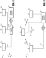
- FIG. 2 depicts an example of a local area network (LAN) connection between MESs within the satellite communication system.
- network 30 includes a LAN router 36 and a LAN links 34, each connecting a respective one of MESs 22_1 to 22_3 to LAN router 36.
- Links 34 may each be a wireless link (e.g., using IEEE 802.11 technology or Bluetooth ® ), or a wired link, e.g., an electrical or optical link employing Ethernet technology. Any other suitable type of LAN technology may be implemented.
- FIG. 3 depicts an example of an ad hoc network connection between MESs within the satellite communication system.
- network 30 may be formed by ad hoc network processing circuitry within each of MESs 22 and a wireless communication interface within each of MESs 22. These circuits may form a wireless link 32_a between MES 22_1 and 22_2; a wireless link 32_b between MES 22_2 and 22_3; and a wireless link 32_c between MES 22_1 and 22_3.
- End user equipment 40 may be coupled to each of MESs 22 through a respective wireless or wired link 42, to receive downlink data signal DD and/or transmit uplink data signal UD to one or more of the MESs 22.
- signals DD and UE are communicated just between the leader MES 22_i and EUE 40 over the link 42 therebetween.
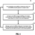
- an auto-configuration operation occurs (S404) in which one MES 22_i among the MESs is configured in the leader mode (thereby becoming the designated leader MES 22_i) and each remaining MES 22 of the group of MESs is configured in the follower mode.
- the leader MES 22_i manages combining / dividing of satellite-related signals communicated between itself and the remaining MESs. Examples of such management are presented below.
- the management may involve, on downlink, commanding the remaining MESs 22 to transmit their satellite-related signals to the leader MES 22_i and performing digital / analog combining of all the satellite-related signals.
- the management may also involve generating and transmitting synchronization / timing signals to the remaining MESs to facilitate phase adjustment of the satellite-related signals sufficient to realize a virtual array.
- the management may involve analogous operations for uplink signals.
- the flow then returns to operation S402, where the operations may be repeated, such that the auto-negotiation may be ongoing throughout the operation of MES unit 20.
- an auto-negotiation engine running within each of the MESs may recognize that one of the MESs is designated to be an initial leader MES by default. Thereafter, if the leader MES fails, one of the remaining MESs 22 may be selected as the new leader MES.
- each of the MESs including the leader MES 22_i, may be configured to transmit status messages to one or more of the other MESs 22, where a status indicating a "keep alive" state for any given MES 22_j may indicate that the MES 22_j is operating satisfactorily. If, however, the status message transmitted by the leader MES 22_i indicates that its operations no longer meet predetermined specifications (or status messages are no longer being transmitted), then the auto-negotiation operation S402 may immediately select a new leader MES.
- Another example may involve a scenario in which only MES 22_i (e.g., the leader MES) is designated to transmit an uplink signal satellite 15.
- the one MES 22_i may continually monitor its link condition with satellite 15 by monitoring receive signal quality of downlink signals. If the receive signal quality falls below a first threshold due to the presence of an obstacle or other reason, MES_i may inform the other MESs, whereupon the auto-negotiation operation S402 may select a new MES 22_j to perform the uplink signal transmitting (e.g., if the receive signal quality of the new MES 22_j is above a second threshold, where the second threshold may be set higher than the first threshold).
- the new MES 22_j may also reconfigure as the leader MES while the previous leader MES 22_i may reconfigure as a follower MES.
- FIG. 5A illustrates example signal flow between MESs in the satellite communication system of FIG. 1 , during reception of downlink signals.
- MESs 22_1, 22_2 and 22_3 may receive the downlink signal as a received downlink signal SD_1, SD_2 and SD_3, respectively, and derive respective satellite-related signals S1, S2 and S3 therefrom.
- Each MES 22 may include an RF front end 72 (e.g., a transceiver front end) coupled to its associated antenna 24; a combiner/divider 80; a modem 88; and an input/output (I/O) interface 75.
- RF front end 72 e.g., a transceiver front end
- MES 22_1 is the leader MES and the remaining MESs, MES_2 and MES_3, are follower MESs.
- combiner/divider 80 operates in the digital domain and signals S1-S3 are digital signals (understood as baseband signals) obtained after sampling of analog baseband signals output by RF front end 72 (discussed further below in connection with FIG. 6A ).
- Signals S2 and S3 may be sent from MESs 22_2 and 22_3 to MES_1 over links 62_a and 62_c, respectively, of network 30.
- Signal T1 from leader MES 22_1 may further include configuration data to enable / facilitate communication with satellite 15, such as channel configuration data, e.g., tuning, center frequency, bandwidth and/or symbol/sample rate data associated with an allocated channel(s) for communication between satellite 15 and MES 22_1.
- configuration data may have been obtained by the leader MES 22_1 during an initial communication exchange with satellite 15.
- FIG. 5B illustrates example signal flow between MESs in the satellite communication system of FIG. 1 , during transmission of uplink signals.
- Modem 88 of leader MES 22_1 may receive uplink data signal DU from EUE 40, modulate the same to generate an uplink modulated signal SMU.
- Signal SMU may be output to combiner/divider 80 of MES 22_1, where it may be divided into divided signals S4, S5 and S6.
- the dividing may occur prior to sampling within MES 22_1.
- the dividing may occur after sampling.
- Divided signals S4 and S5 may be routed to through I/O's 75 to respective RF front ends 72 of MESs 22_2 and 22_3, whereas signal S6 may be routed to RF front end 72 of MES 22_1.
- RF front ends 72 of MESs 22_1, 22_2 and 22_3 may then generate uplink signals SU_1, SU_2 and SU_3, respectively, which may be synchronously transmitted so as to combine at satellite 15 into a composite uplink signal SU.
- Signal SU may have higher signal strength and better signal quality characteristics as compared to transmitting an uplink signal from only one of MESs 22.
- Each MES 22 may include an RF front-end 72, a sampler 82, a digital domain combiner/divider 80b, a modem 88, an I/O interface 75, a controller 102, a memory 104, an auto-negotiation engine 90, an auto-discovery engine 112, a signal quality analyzer 114, synchronization circuitry 108, and an analog domain combiner/divider 80a. In other embodiments, one or more of these components may be omitted. Although shown separately, some of these components (e.g., 90, 112, 114, 88, 80b, and/or 108) may be combined within a single processing device, e.g., a processor of controller 102 executing instructions to carry out their functionality.
- a single processing device e.g., a processor of controller 102 executing instructions to carry out their functionality.
- Controller 102 may control / coordinate overall operations of MES 22, such as the auto-configuration operations and ad hoc network formation operations described earlier. Controller 102 may also serve to manage the combining/dividing operations of MES unit 20. For example, when MES 22_1 is a leader MES, controller 102 of MES 22_1 may manage the combining/dividing by sending commands to combiner/divider 80 of MES 22_1 to carry out the combining / dividing; and sending commands to the other MESs to send their satellite-related signals S2, S3 to MES 22_1. When MES 22_1 is a follower MES, the combiner/divider 80 of another MES 22 may perform the combining/dividing and the management thereof.
- Controller 102 may also coordinate other processing-related functions described herein such as the auto-negotiation, auto-discovery, signal quality analysis, modem, synchronization and I/O interface operations. The latter may involve coordinating the exchange of status signals, auto-negotiation signals, auto-discovery signals (e.g., heartbeat signals), configuration data, satellite-related signals, etc. with the other MESs. Controller 102 may include a processor / control logic to implement its functionality. Processing circuitry within controller 102 may also execute instructions read from memory 104 to perform at least some of its functions. Auto-negotiation engine 90 may perform the auto-negotiation operations of method 400 discussed earlier.
- Auto-negotiation engine 90 may perform the auto-negotiation operations of method 400 discussed earlier.
- FIG. 6B is an example functional block diagram of an MES configured to communicate RF signals with other MESs in the satellite communication system, according to an embodiment.
- analog baseband signals (another example of satellite-related signals) are communicated between MESs, and combining / dividing of satellite-related signals occurs in the analog domain.
- a downlink example will be discussed hereafter. Analogous operations may occur for uplink signals.
- satellite-related signals SD_2' and SD_3' may be derived by MESs 22_2 and 22_3 in the same or similar manner as signal SD_1'.
- Signals SD_1' to SD_3' may be input to analog combiner/divider 80a, which coherently combines the same to generate a combined analog signal SCA.
- Signal SCA may then be sampled by sampler 82 to generate a sampled signal SCA', which is applied to modem 88.
- Modem 88 may then generate downlink data signal DD from sampled signal SCA'. Analogous operations may occur for dividing and transmitting uplink signals.
- FIG. 7 depicts example electronically steered antennas that may be used within respective MESs according to an embodiment.
- MESs 22_1 and 22_3 are shown to include electronically steered antenna 24a and 24b, respectively, such as a phased array.
- Antenna 24a includes a linear or planar array 170 of M antenna elements 175_1 to 175_M, and a 1:M RF combiner/divider 160.
- Antenna 24b includes a linear or planar array 190 of L antenna elements 195_1 to 195_L, and a 1:L RF combiner/divider (C/D) 180, where L may differ from M.
- C/D 1:L RF combiner/divider
- Phase shifters and/or variable amplifiers may be included within array 170 and/or C/D 180 to achieve beam steering / dynamic beam pattern formation under the control of control signals provided by controller 102 of MES 22_1.
- controller 102 of MES 22_3 may provide control signals to phase shifters / amplifiers of antenna 24b to realize beam steering / dynamic beam pattern formation.
- FIG. 7 also illustrates that inter-MES combining may occur in the analog domain and/or the digital domain, as described above.
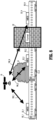
- FIG. 8 illustrates an application of the satellite communication system in which MESs are located on different rail cars of a train.
- obstacles such as O1 (a tree) or O2 (a tunnel) interrupt the line-of-sight links, receive signal quality of downlink signals to respective MESs may fall below an acceptable threshold (e.g., the "first threshold" discussed earlier).
- MES 22_3 of MES unit 20 is designated (and thereby configured) to transmit uplink signals
- a different MES e.g., MES_1 in FIG. 8 (with a received signal quality metric above a second threshold) may be re-selected as the transmitting MES.
- the transmitting MES 22 may also be designated as the leader MES 22.
- a signal quality metric include absolute receive signal level, signal to noise ratio (SNR), signal to interference and noise (SINR), Energy per bit / Noise-spectral density (EbNo), Energy per symbol / Noise-spectral density (EsNo), Error Vector Magnitude (EVM), Bit Error Rate (BER), and any combination thereof.
- SNR signal to noise ratio
- SINR signal to interference and noise
- EbNo Energy per bit / Noise-spectral density
- EsNo Energy per symbol / Noise-spectral density
- EVM Error Vector Magnitude
- BER Bit Error Rate
- the various illustrative logical blocks, engines, and circuits described in connection with the present disclosure may be implemented or performed with processing circuitry within any of the MESs 22 (e.g., within controller 102), that may read and execute instructions from a non-transitory recording medium (e.g., memory 104).
- the processing circuitry may include a general purpose processor, a digital signal processor (DSP), an application specific integrated circuit (ASIC), a field programmable gate array signal (FPGA) or other programmable logic device (PLD), discrete gate or transistor logic, discrete hardware components or any combination thereof designed to perform the functions described herein.
- a general purpose processor may be a microprocessor, but in the alternative, the processor may be any commercially available processor, controller, microcontroller or state machine.
- a processor may also be implemented as a combination of computing devices, e.g., a combination of a DSP and a microprocessor, a plurality of microprocessors, one or more microprocessors in conjunction with a DSP core, or any other such configuration.
- functions described above may be implemented using hardware, software, firmware, or any combination thereof. If implemented in software, the functions may be stored as one or more instructions or code on a non-transitory computer-readable medium (e.g., memory 104).
- a computer-readable medium include both computer storage media and communication media including any medium that facilitates transfer of a computer program from one place to another.
- a storage medium may be any available medium that can be accessed by a computer / processing circuitry. Examples of such computer-readable media include RAM, ROM, EEPROM, CD-ROM or other optical disc storage, magnetic disc storage or other magnetic storage devices, or any other medium that can be used to store desired program code in the form of instructions or data structures and that can be accessed by a computer / processing circuitry.
Landscapes
- Engineering & Computer Science (AREA)
- Physics & Mathematics (AREA)
- Astronomy & Astrophysics (AREA)
- Aviation & Aerospace Engineering (AREA)
- General Physics & Mathematics (AREA)
- Computer Networks & Wireless Communication (AREA)
- Signal Processing (AREA)
- Radio Relay Systems (AREA)
Abstract
Description
- This disclosure relates generally to satellite communications and more particularly to satellite communication with mobile earth stations (MESs).
- A mobile earth station (MES) is mobile wireless equipment capable of communicating (transmitting and/or receiving) signals to a satellite. An MES can be a hand-held portable wireless device, or a wireless device fixedly mounted to a mobile transporter such as a rail car of a train, a watercraft, a vehicle, or a robot. In some cases, a plurality of MESs are mounted to different locations on a large mobile transporter such a train. By providing a plurality of MESs that may operate individually or together for redundant communication, reliability of communications with one or more satellites may be improved.
- In an aspect of the present disclosure, a communication system includes a plurality of MESs arranged at different locations and operating as a unit to communicate with one or more satellites. One of the MESs is configured in a leader mode and each remaining MES of the MESs is configured in a follower mode based on a result of an auto-negotiation. In the leader mode the one MES manages combining / dividing of satellite-related signals communicated between the one MES and each of the remaining MESs.
- In a downlink path, the satellite-related signals may be digital or analog baseband signals derived from downlink satellite signals received by each of the remaining MESs. In an uplink path, the satellite-related signals may also be digital or analog baseband signals, divided by the one MES operating in the leader mode, corresponding to a transmit path uplink data signal provided from end user equipment.
- In another aspect, a first MES, among a plurality of MESs arranged at different locations and operational as a unit to communicate with one or more satellites, includes: an antenna for transmitting an uplink signal and/or receiving a downlink signal from the one or more satellites; a transceiver front end coupled to the antenna; a modem for transmitting and/or receiving data signals to/from external end user equipment; memory; and a controller coupled to the transceiver front end and the modem. The controller executes instructions read from the memory to: auto-negotiate with remaining MESs of the plurality of MESs to determine which one of the MESs should operate in a leader mode; configure the first MES in the leader mode and each of the remaining MESs in a follower mode based on a result of the auto-negotiation; and manage, when the first MES is configured in the leader mode, combining/dividing of satellite-related signals communicated between the first MES and each of the remaining MESs.
- In another aspect, a method performed by a group of MESs to communicate with one or more satellites includes auto-negotiating among the group of MESs to determine which one of the MESs should operate in a leader mode; configuring one MES of the set in the leader mode and each remaining MES of the MESs in a follower mode based on a result of the auto-negotiation; and managing, by the one MES configured in the leader mode, combining/dividing of satellite related signals communicated between the one MES and each of the remaining MESs.
- In still another aspect, a non-transitory computer-readable recording medium stores instructions that, when executed by a controller, cause a first MES, among a plurality of MESs arranged at different locations and operational as a unit to communicate with one or more satellites, to implement the method outlined above.
- The above and other aspects and features of the disclosed technology will become more apparent from the following detailed description, taken in conjunction with the accompanying drawings in which like reference characters indicate like elements or features. Various elements of the same or similar type may be distinguished by annexing the reference label with an underscore / dash and second label that distinguishes among the same / similar elements (e.g., _1, _2), or directly annexing the reference label with a second label. However, if a given description uses only the first reference label, it is applicable to any one of the same / similar elements having the same first reference label irrespective of the second label. Elements and features may not be drawn to scale in the drawings.
-
FIG. 1 illustrates a satellite communication system according to an embodiment. -
FIG. 2 depicts an example of a local area network (LAN) connection between MESs within the satellite communication system. -
FIG. 3 depicts an example of an ad hoc network connection between MESs within the satellite communication system. -
FIG. 4 is a flow chart outlining an example method of satellite communication with MESs according to an embodiment. -
FIG. 5A illustrates example signal flow between MESs in the satellite communication system ofFIG. 1 , during reception of downlink signals. -
FIG. 5B illustrates example signal flow between MESs in the satellite communication system ofFIG. 1 , during transmission of uplink signals. -
FIG. 6A is an example functional block diagram of an MES configured to communicate baseband signals with other MESs in the satellite communication system, according to an embodiment. -
FIG. 6B is an example functional block diagram of an MES configured to communicate radio frequency (RF) signals with other MESs in the satellite communication system, according to an embodiment. -
FIG. 7 depicts example electronically steered antennas that may be used within respective MESs according to an embodiment. -
FIG. 8 illustrates an application of the satellite communication system in which MESs are located on different rail cars of a train. - The following description, with reference to the accompanying drawings, is provided to assist in a comprehensive understanding of certain exemplary embodiments of the technology disclosed herein for illustrative purposes. The description includes various specific details to assist a person of ordinary skill the art with understanding the technology, but these details are to be regarded as merely illustrative. For the purposes of simplicity and clarity, descriptions of well-known functions and constructions may be omitted when their inclusion may obscure appreciation of the technology by a person of ordinary skill in the art.
- Herein, the phrase "communicating signals" (or like forms) encompasses unidirectional and bidirectional communication. Thus, when a first device communicates signals with a second device, the first device transmits signals to and/or receives signals from the second device.
- Herein, the phrase "combining / dividing" or like forms means combining and/or dividing.
- Herein, the slash symbol " /" connecting two items signifies and/or ("and" or "or"), unless the context indicates otherwise. In other words, both items are present in one example, but only one of the items is present in another example.
-
FIG. 1 illustrates a satellite communication system, 10, according to an embodiment.System 10 may include asatellite 15 that communicates over a satellite channel with a group of spatially distributed modularized, self contained MESs, e.g., 22_1, 22_2 and 22_3, that form anMES unit 20 in which MESs 22_1 to 22_3 operate together with respect tosatellite 15. Although onesatellite 15 and three MESs are illustrated and described, MESunit 20 may concurrently communicate with at least one other satellite over another satellite channel in the same way as described below forsatellite 15. Further, although three MESs are illustrated and described,MES unit 20 may have exactly two MESs, or four or more MESs in other embodiments. At any given time, MESs 22_1, 22_2 and 22_3 may be located on different mobile transporters 50_1, 50_2 and 50_3, respectively, which may be different locations of a common transporter such as a train or vessel. In other examples, transporters 50_1 to 50_3 are different vehicles, different robots, different humans (for hand-held or wearable MESs), and so forth. - Some examples of
satellite 15 include a low earth orbit (LEO) satellite, a medium earth orbit (MEO) satellite, a geosynchronous equatorial orbit (GEO) satellite, or an elliptical orbit satellite. The types of data communicated betweensatellite 15 andMES unit 20 may include Internet-generated data, private network based data, navigational data, weather data, scientific data, and application data.Satellite 15 may be communicatively connected to a ground station (not shown) and act as a transponder to route data between the ground station andMES unit 20. -
Satellite 15 may transmit a downlink signal SD toMESs 22 and/or receive an uplink signal SU from at least one of theMESs 22. MESunit 20 may be transparent tosatellite 15 in the sense thatsatellite 15 may operate as though it is communicating with a single MES 22. To this end, on downlink,satellite 15 may transmit a single signal SD intended for asingle MES 22 following an identification exchange, without knowing that the signal SD is received and processed at multiple MESs. The signal SD may be received by each of the MESs 22_1 to 22_3.MESs 22 may be communicatively coupled with one another through anetwork 30, e.g., a wireless or wired (electrical or optical) local area network (LAN), or an ad hoc network. The downlink signals received by each of theMESs 22 may be shared overnetwork 30 between theMESs 22, and combined, to obtain a composite signal of higher quality and reliability than that realizable with just asingle MES 22. The combined signal may be processed (e.g., downconverted and demodulated) by one or more of theMESs 22 to generate a composite data signal DD that is output to end user equipment (EUE) 40. Some examples of EUE 40 include a stand-alone computer(s) coupled to a monitor (e.g., for use by a central operator oftransporter 50 for real time communication with respect to transporter 50); mobile devices for end users ontransporter 50 connected to the Internet via thesatellite system 10; or a data storage system to collect satellite data for later use. - As an example, an obstacle may exist between MES 22_1 and
satellite 15 causing line-of-sight blockage that reduces receive signal quality at MES 22_1. However, no such obstacle may exist between the other MESs 22_2 and 22_3 andsatellite 15. In this case,MES unit 20 may generate a composite receive signal comprised primarily of the receive signals from MESs 22_2 and 22_3, whereby receive signal quality of the composite receive signal may still be satisfactory. On the other hand, if MES 22_1 was the sole MES handling the satellite communication in this scenario, receive signal quality might be temporarily unsatisfactory. - Similarly, for uplink signal transmissions, in some
embodiments satellite 15 may have initially set up a communication session with a single MES 22_i ofMES unit 20. This may have occurred via an initial handshake in which an identifier for MES_i was received in a frame of an uplink signal. Thereafter, MESs 22_1 to 22_3 may each transmit a shifted and/or weighted portion of the same uplink signal in a synchronized fashion, which synchronously arrive to form a composite uplink signal SU atsatellite 15. (A similar scheme could also be used for the uplink handshake signals.)Satellite 15 may not, and need not, recognize that the actual source of the uplink signal is a plurality of MESs each transmitting a portion of the signal. Thus, the contributions of the other MESs (i.e., other than MES_i) may be transparent tosatellite 15. - In other embodiments, such individual portions of uplink signals are not transmitted by
multiple MESs 22, such that only asingle MES 22 transmits the uplink signal. In this case, however, if an obstacle is detected to exist between the transmitting MES and satellite 15 (e.g., through detection of a reduced signal quality in a received downlink signal from satellite 15) then the transmittingMES 22 may be switched to another one of theMESs 22. - In
system 10, an auto-negotiation may be performed by theMESs 22 ofMES unit 20 to determine which one of theMESs 22 should be configured in a "leader mode". To this end, a wide variety of leader election algorithms could be used, of which some examples employ features such as time-based leases and heartbeat communication for lease refresh. - At any given time, as a result of the auto-negotiation, a single one of the
MESs 22 ofMES unit 20 may be configured in the leader mode, and the remainingMESs 22 ofMES unit 20 may each be configured in a "follower mode". Hereafter, anMES 22 configured in the leader mode may be referred to as the leader MES 22_i (i= any integer from 1 to N in anMES unit 20 having N MESs), and anyMES 22 configured in the follower mode may be referred to as a follower MES. The leader MES 22_i may manage combining / dividing of satellite-related signals communicated between the leader MES 22_i and each of the remaining MESs 22 (the follower MESs). On downlink, a satellite-related signal of any MES 22_j (j = 1 to N) may be a baseband signal derived from the portion of the downlink signal SD received by that MES 22_j. On uplink, a satellite-related signal may loosely refer to either a signal derived from the uplink data signal DU, or a signal derived from a divided portion of the uplink data signal DU. - Each
MES 22 ofMES unit 20 includes arespective antenna 24, which may be a fixed antenna forming a fixed beam pattern and pointing direction. Alternatively,antenna 24 forms a steerable beam and/or a dynamically adjustable beam shape, which may be steered electronically or mechanically. In the case of electronic steering, anyantenna 24 may be a phased array. In any case, when MESs 22_1 to 22_3 operate as anMES unit 20 to combine received portions of downlink signal SD and/or transmit respective portions of uplink signal SU, they may be understood to form a "terminal array" in which a virtual antenna has a larger effective aperture than any of theindividual antennas 24. -
MES unit 20 may be configured in various embodiments for: (i) digital combining / beamforming and/or analog combining / beamforming of uplink / downlink signals; (ii) auto-discovery / auto-configuration; (iii) use as a standalone unit or for adding additional assemblies to improve upon individual MES effective aperture size under nominal conditions, thereby improving overall spectral efficiency; (iv) allowing for a larger effective aperture (collectively formed by all of the MESs) to be installed under varying MES platform space constraints; and/or (v) ease of use and increased availability. - When
MES unit 20 is configured with analog combining / beamforming, functionality may be included for individually adjusting the amplitude and phase of a plurality of RF signals, sent to / received from the MESs 22_1 to 22_3 via analog techniques, in order to maximize receive signal strength and transmit signal strength as desired. This may involve intra-MES analog combining and/or inter-MES analog combining. Intra-MES analog combining may be implemented whenantenna 24 is embodied as a phased array. In this case, per-element analog gain / phase adjustments and intra-MES combining may be made within eachindividual MES 22 via analog mechanisms to steer / adjust a beam formed by that MES (for uplink / downlink beams). Inter-MES combining may be implemented after down-conversion for downlink signals, and/or prior to up-conversion for uplink signals. (See, e.g.,FIG. 7 .) - When
MES unit 20 is configured with digital combining / beamforming, functionality may be included for individually adjusting the amplitude and phase of a plurality of RF signals, sent to / received from the MESs 22_1 to 22_3 via digital signal processing techniques, in order to similarly maximize the receive signal strength and transmit signal strength as desired. Whenantenna 24 of an MES 22_j is a phased array, the digital combining may include optimal digital combining across a plurality of sub-arrays of the phased array. Additionally or alternatively, the digital combining is inter-MES combining. On downlink, the inter-MES digital combining may occur with respect to received satellite signals after downconversion and sampling. On uplink, the inter-MES combining may occur with respect to uplink data signals after modulation and prior to upconversion. (See, e.g.,FIG. 7 .) -
MES unit 20 may also be configured with hybrid analog and digital combining functionality. For example, an MES 22_j may include intra-MES analog combining functionality as described above, as well as the above-described inter-MES digital combining functionality. -
MES unit 20 may be configured with auto-discovery functionality ("auto-discovery"). With auto-discovery, MESs 22_1 to 22_3 may establish communications among themselves upon power-up vianetwork 30. One way to perform auto-discovery is by incorporating use of broadcast heartbeat messages at regular periodic intervals (e.g. 1/second) from each of the MESs 22 (or from at least theleader MES 22 if already established). Upon start-up, anMES 22 may listen for broadcast messages and determine which messages are part of the leader-election process and/or which messages identify an existing leader MES. For instance, an auto-discovery protocol used by the MESs may dictate that a first predetermined value within a field of a heartbeat message frame is indicative of a leader-election process message. However, if a leader has already been established, a second value within the same or different field or frame may identify the current leader. Auto-discovery may further enable configuration files to be automatically loaded to a newly addedMES 22, and signals from the newly added MES may be optimally combined with those of the existing MESs 22_1 to 22_3. Auto-discovery may improve overall reliability by allowing a newly addedMES 22 to become a new leader MES if the current leader MES fails. -
MES unit 20 may further include auto-configuration functionality ("auto-configuration"). With collective auto-configuration and auto-discovery functionality, MESs 22_1 to 22_3 may establish communications with one another upon power-up vianetwork 30. Further, any newly added MESs may be automatically configured (initially) as a follower MES. - With auto-configuration, configuration data may be replicated over connected
MESs 22. For example, the leader MES may provide the configuration data to the follower MESs. In addition,MESs 22 may send status signals to one another, such as "keep alive" messages requesting to be maintained as an active MES withinMES unit 20. Further, a failedleader MES 22 may be automatically replaced by anotherMES 22. -
FIG. 2 depicts an example of a local area network (LAN) connection between MESs within the satellite communication system. Here, an example ofnetwork 30 includes aLAN router 36 and a LAN links 34, each connecting a respective one of MESs 22_1 to 22_3 toLAN router 36.Links 34 may each be a wireless link (e.g., using IEEE 802.11 technology or Bluetooth®), or a wired link, e.g., an electrical or optical link employing Ethernet technology. Any other suitable type of LAN technology may be implemented. Command signals and data signals for the above-discussed auto-negotiation, auto-discovery and auto-configuration operations may be communicated among theMESs 22 ofMES unit 20 under control ofLAN router 36 through LAN links 34. In addition, the above-noted satellite-related signals may be communicated among theMESs 22 throughLAN router 36 andlinks 34 in the same manner.Router 36 may also be coupled to end user equipment (EUE) 40 and route uplink data signal DU fromEUE 40 to the leader MES 22_i and/or route downlink data signal DD from the leader MES 22_i toEUE 40. -
FIG. 3 depicts an example of an ad hoc network connection between MESs within the satellite communication system. Here,network 30 may be formed by ad hoc network processing circuitry within each ofMESs 22 and a wireless communication interface within each ofMESs 22. These circuits may form a wireless link 32_a between MES 22_1 and 22_2; a wireless link 32_b between MES 22_2 and 22_3; and a wireless link 32_c between MES 22_1 and 22_3.End user equipment 40 may be coupled to each ofMESs 22 through a respective wireless or wiredlink 42, to receive downlink data signal DD and/or transmit uplink data signal UD to one or more of theMESs 22. In an embodiment, signals DD and UE are communicated just between the leader MES 22_i andEUE 40 over thelink 42 therebetween. -
FIG. 4 is a flow chart outlining anexample method 400 of satellite communication between a group of MESs and one or more satellites according to an embodiment.Method 400 is discussed below in connection with the above-describedcommunication system 10. Withmethod 400, an auto-negotiation operation (S402) among all MESs 22_1 to MES 22_3 of the group of MESs formingMES unit 20 may take place to determine which one of the MESs should operate in a leader mode (where the remaining MESs would operate in the follower mode). Based on a result of the auto-negotiation, an auto-configuration operation occurs (S404) in which one MES 22_i among the MESs is configured in the leader mode (thereby becoming the designated leader MES 22_i) and each remainingMES 22 of the group of MESs is configured in the follower mode. - Once so configured, the leader MES 22_i manages combining / dividing of satellite-related signals communicated between itself and the remaining MESs. Examples of such management are presented below. In general, the management may involve, on downlink, commanding the remaining
MESs 22 to transmit their satellite-related signals to the leader MES 22_i and performing digital / analog combining of all the satellite-related signals. The management may also involve generating and transmitting synchronization / timing signals to the remaining MESs to facilitate phase adjustment of the satellite-related signals sufficient to realize a virtual array. The management may involve analogous operations for uplink signals. - The flow then returns to operation S402, where the operations may be repeated, such that the auto-negotiation may be ongoing throughout the operation of
MES unit 20. For instance, when all theMESs 22 ofMES unit 20 are first powered up, an auto-negotiation engine running within each of the MESs may recognize that one of the MESs is designated to be an initial leader MES by default. Thereafter, if the leader MES fails, one of the remainingMESs 22 may be selected as the new leader MES. To this end, each of the MESs, including the leader MES 22_i, may be configured to transmit status messages to one or more of theother MESs 22, where a status indicating a "keep alive" state for any given MES 22_j may indicate that the MES 22_j is operating satisfactorily. If, however, the status message transmitted by the leader MES 22_i indicates that its operations no longer meet predetermined specifications (or status messages are no longer being transmitted), then the auto-negotiation operation S402 may immediately select a new leader MES. - Another example may involve a scenario in which only MES 22_i (e.g., the leader MES) is designated to transmit an
uplink signal satellite 15. In this case, the one MES 22_i may continually monitor its link condition withsatellite 15 by monitoring receive signal quality of downlink signals. If the receive signal quality falls below a first threshold due to the presence of an obstacle or other reason, MES_i may inform the other MESs, whereupon the auto-negotiation operation S402 may select a new MES 22_j to perform the uplink signal transmitting (e.g., if the receive signal quality of the new MES 22_j is above a second threshold, where the second threshold may be set higher than the first threshold). The new MES 22_j may also reconfigure as the leader MES while the previous leader MES 22_i may reconfigure as a follower MES. -
FIG. 5A illustrates example signal flow between MESs in the satellite communication system ofFIG. 1 , during reception of downlink signals. Whensatellite 15 transmits downlink signal SD, MESs 22_1, 22_2 and 22_3 may receive the downlink signal as a received downlink signal SD_1, SD_2 and SD_3, respectively, and derive respective satellite-related signals S1, S2 and S3 therefrom. EachMES 22 may include an RF front end 72 (e.g., a transceiver front end) coupled to its associatedantenna 24; a combiner/divider 80; amodem 88; and an input/output (I/O)interface 75. - In the example of
FIG. 5A , MES 22_1 is the leader MES and the remaining MESs, MES_2 and MES_3, are follower MESs. In a digital combining embodiment, combiner/divider 80 operates in the digital domain and signals S1-S3 are digital signals (understood as baseband signals) obtained after sampling of analog baseband signals output by RF front end 72 (discussed further below in connection withFIG. 6A ). Signals S2 and S3 may be sent from MESs 22_2 and 22_3 to MES_1 over links 62_a and 62_c, respectively, ofnetwork 30. These links may be wireless links such as 32_a and 32_c of an ad hoc network described earlier, or wired /wireless links 34 coupled to a LAN router 36 (although shown directly connected betweenMESs 22 inFIG. 5A for simplicity). Another link 62_b may similarly communicatively couple MESs 22_2 and 22_3. - Links 62_a to 62_c may also carry control / data signals T1, T2 and T3 between associated MESs. Any of signals T1-T3 may include status signals such as keep alive signals; signal quality metric signals to inform
other MESs 22 of the downlink signal quality received at any given MES 22_j; device identification signals; auto-negotiation signals communicated during the above-discussed auto-negotiation operations; auto-discovery signals communicated during the above-discussed auto-discovery operations; and so forth. Signal T1 from leader MES 22_1 may further include configuration data to enable / facilitate communication withsatellite 15, such as channel configuration data, e.g., tuning, center frequency, bandwidth and/or symbol/sample rate data associated with an allocated channel(s) for communication betweensatellite 15 and MES 22_1. Such configuration data may have been obtained by the leader MES 22_1 during an initial communication exchange withsatellite 15. - Signals S1-S3 are alternatively analog signals output directly by RF
front end 75, in which case combiner /divider 80 operates in the analog domain to combine signals prior to sampling. In either case (digital or analog combining), combiner/divider 80 of the leader MES 22_1 may output a combined signal SCB, andmodem 88 may demodulate signal SCB to derive downlink signal DD therefrom and output the same to end user equipment (EUE) 40. -
FIG. 5B illustrates example signal flow between MESs in the satellite communication system ofFIG. 1 , during transmission of uplink signals. (Signals T1-T3 are not shown inFIG. 5B but may be similarly exchanged betweenMESs 22 over links 62_a to 62_c as described above.)Modem 88 of leader MES 22_1 may receive uplink data signal DU fromEUE 40, modulate the same to generate an uplink modulated signal SMU. Signal SMU may be output to combiner/divider 80 of MES 22_1, where it may be divided into divided signals S4, S5 and S6. In a digital combining embodiment, the dividing may occur prior to sampling within MES 22_1. In an analog combining embodiment the dividing may occur after sampling. Divided signals S4 and S5 may be routed to through I/O's 75 to respective RF front ends 72 of MESs 22_2 and 22_3, whereas signal S6 may be routed to RFfront end 72 of MES 22_1. RF front ends 72 of MESs 22_1, 22_2 and 22_3 may then generate uplink signals SU_1, SU_2 and SU_3, respectively, which may be synchronously transmitted so as to combine atsatellite 15 into a composite uplink signal SU. Signal SU may have higher signal strength and better signal quality characteristics as compared to transmitting an uplink signal from only one ofMESs 22. -
FIG. 6A is an example functional block diagram of an MES configured to communicate baseband signals with other MESs in the satellite communication system, according to an embodiment. In this example, digital baseband signals (an example of satellite-related signals) are communicated between MESs, and combining / dividing of satellite-related signals occurs in the digital domain. A downlink example will be discussed hereafter. Analogous operations may occur for uplink signals. InFIG. 6A , example functional components are shown for MES 22_1, assumed to be operating in the leader mode. Each of the remainingMESs 22 may include similar components, and may operate in the same way when designated as a leader MES. EachMES 22 may include an RF front-end 72, asampler 82, a digital domain combiner/divider 80b, amodem 88, an I/O interface 75, acontroller 102, amemory 104, an auto-negotiation engine 90, an auto-discovery engine 112, asignal quality analyzer 114,synchronization circuitry 108, and an analog domain combiner/divider 80a. In other embodiments, one or more of these components may be omitted. Although shown separately, some of these components (e.g., 90, 112, 114, 88, 80b, and/or 108) may be combined within a single processing device, e.g., a processor ofcontroller 102 executing instructions to carry out their functionality. - RF front-
end 72 may include a downconverter to down-convert downlink signals, and an upconverter to up-convert uplink signals; filters; amplifiers; etc. RFfront end 72 may process (e.g., down-convert, filter, amplify, etc.) downlink signal SD_1 received fromantenna 24 to derive a satellite-related signal SD_1'. This signal may be sampled bysampler 82 to derive a sampled signal S1. RF front ends 75 andsamplers 82 of the remainingMESs 22 may similarly derive sampled signals S2 and S3. Digital domain combiner /divider 80b may combine signals S1-S3 in the digital domain to thereby generate a combined digital signal SCD. Signal SCD may be output tomodem 88, which demodulates the same to generate downlink data signal DD. -
Controller 102 may control / coordinate overall operations ofMES 22, such as the auto-configuration operations and ad hoc network formation operations described earlier.Controller 102 may also serve to manage the combining/dividing operations ofMES unit 20. For example, when MES 22_1 is a leader MES,controller 102 of MES 22_1 may manage the combining/dividing by sending commands to combiner/divider 80 of MES 22_1 to carry out the combining / dividing; and sending commands to the other MESs to send their satellite-related signals S2, S3 to MES 22_1. When MES 22_1 is a follower MES, the combiner/divider 80 of anotherMES 22 may perform the combining/dividing and the management thereof.Controller 102 may also coordinate other processing-related functions described herein such as the auto-negotiation, auto-discovery, signal quality analysis, modem, synchronization and I/O interface operations. The latter may involve coordinating the exchange of status signals, auto-negotiation signals, auto-discovery signals (e.g., heartbeat signals), configuration data, satellite-related signals, etc. with the other MESs.Controller 102 may include a processor / control logic to implement its functionality. Processing circuitry withincontroller 102 may also execute instructions read frommemory 104 to perform at least some of its functions. Auto-negotiation engine 90 may perform the auto-negotiation operations ofmethod 400 discussed earlier. Similarly, auto-discovery engine 112 andsignal quality analyzer 114 may perform the above-discussed auto-discovery and signal quality measurement operations, respectively.Synchronization circuitry 108 of leader MES 22_1 may generate synchronization signals (e.g., included in a field of signal T1) transmitted to theother MESs 22 ofMES unit 20, to enable synchronization of the downlink satellite-related signals S1-S3. This may allow signals S1-S3 to be coherently generated and combined, and thereby improve overall signal quality / reliability ofMES unit 20. -
FIG. 6B is an example functional block diagram of an MES configured to communicate RF signals with other MESs in the satellite communication system, according to an embodiment. In this example, analog baseband signals (another example of satellite-related signals) are communicated between MESs, and combining / dividing of satellite-related signals occurs in the analog domain. A downlink example will be discussed hereafter. Analogous operations may occur for uplink signals. - As shown in
FIG. 6B , satellite-related signals SD_2' and SD_3' may be derived by MESs 22_2 and 22_3 in the same or similar manner as signal SD_1'. Signals SD_1' to SD_3' may be input to analog combiner/divider 80a, which coherently combines the same to generate a combined analog signal SCA. Signal SCA may then be sampled bysampler 82 to generate a sampled signal SCA', which is applied tomodem 88.Modem 88 may then generate downlink data signal DD from sampled signal SCA'. Analogous operations may occur for dividing and transmitting uplink signals. -
FIG. 7 depicts example electronically steered antennas that may be used within respective MESs according to an embodiment. Here, MESs 22_1 and 22_3 are shown to include electronically steeredantenna Antenna 24a includes a linear orplanar array 170 of M antenna elements 175_1 to 175_M, and a 1:M RF combiner/divider 160.Antenna 24b includes a linear orplanar array 190 of L antenna elements 195_1 to 195_L, and a 1:L RF combiner/divider (C/D) 180, where L may differ from M. Phase shifters and/or variable amplifiers (not shown) may be included withinarray 170 and/or C/D 180 to achieve beam steering / dynamic beam pattern formation under the control of control signals provided bycontroller 102 of MES 22_1. Similarly,controller 102 of MES 22_3 may provide control signals to phase shifters / amplifiers ofantenna 24b to realize beam steering / dynamic beam pattern formation.FIG. 7 also illustrates that inter-MES combining may occur in the analog domain and/or the digital domain, as described above. -
FIG. 8 illustrates an application of the satellite communication system in which MESs are located on different rail cars of a train. In this example, MESs MES_1, MES_2 and MES_N (N = 3 or higher) are located on different respective rail cars 50_1, 50_2 and 50_N, and communicate signals withsatellite 15 over line-of-sight links 199_1, 199_2 and 199_N, respectively. However, if obstacles such as O1 (a tree) or O2 (a tunnel) interrupt the line-of-sight links, receive signal quality of downlink signals to respective MESs may fall below an acceptable threshold (e.g., the "first threshold" discussed earlier). In an embodiment in which only a single MES, e.g., MES 22_3 ofMES unit 20, is designated (and thereby configured) to transmit uplink signals, if the receive signal quality falls below the first threshold, a different MES, e.g., MES_1 inFIG. 8 (with a received signal quality metric above a second threshold) may be re-selected as the transmitting MES. The transmittingMES 22 may also be designated as theleader MES 22. Some examples of a signal quality metric include absolute receive signal level, signal to noise ratio (SNR), signal to interference and noise (SINR), Energy per bit / Noise-spectral density (EbNo), Energy per symbol / Noise-spectral density (EsNo), Error Vector Magnitude (EVM), Bit Error Rate (BER), and any combination thereof. - The various illustrative logical blocks, engines, and circuits described in connection with the present disclosure may be implemented or performed with processing circuitry within any of the MESs 22 (e.g., within controller 102), that may read and execute instructions from a non-transitory recording medium (e.g., memory 104). The processing circuitry may include a general purpose processor, a digital signal processor (DSP), an application specific integrated circuit (ASIC), a field programmable gate array signal (FPGA) or other programmable logic device (PLD), discrete gate or transistor logic, discrete hardware components or any combination thereof designed to perform the functions described herein. A general purpose processor may be a microprocessor, but in the alternative, the processor may be any commercially available processor, controller, microcontroller or state machine. A processor may also be implemented as a combination of computing devices, e.g., a combination of a DSP and a microprocessor, a plurality of microprocessors, one or more microprocessors in conjunction with a DSP core, or any other such configuration.
- In one or more aspects, functions described above may be implemented using hardware, software, firmware, or any combination thereof. If implemented in software, the functions may be stored as one or more instructions or code on a non-transitory computer-readable medium (e.g., memory 104). Examples of a computer-readable medium include both computer storage media and communication media including any medium that facilitates transfer of a computer program from one place to another. A storage medium may be any available medium that can be accessed by a computer / processing circuitry. Examples of such computer-readable media include RAM, ROM, EEPROM, CD-ROM or other optical disc storage, magnetic disc storage or other magnetic storage devices, or any other medium that can be used to store desired program code in the form of instructions or data structures and that can be accessed by a computer / processing circuitry.
- While the technology described herein has been particularly shown and described with reference to example embodiments thereof, it will be understood by those of ordinary skill in the art that various changes in form and details may be made therein without departing from the spirit and scope of the claimed subject matter as defined by the following claims and their equivalents.
- The following numbered clauses provide features useful for understanding the present disclosure:
- 1. A communication system (10) comprising:
- a plurality of mobile earth stations, MESs (22_1, 22_2, 22_3), arranged at different locations and operating as a unit (20) to communicate with one or more satellites (15),
- wherein one MES (22_1) of the plurality of MESs is configured in a leader mode and each remaining MES of the MESs (22_2, 22_3) is configured in a follower mode based on a result of an auto-negotiation, wherein in the leader mode the one MES manages combining / dividing of satellite-related signals (S2-S5) communicated between the one MES and each of the remaining MESs.
- 2. The communication system (10) of
clause 1, wherein:
the one MES manages combining of the satellite-related signals, and each of the satellite-related signals is a baseband signal (S2, S3) derived from a downlink satellite signal (SD_2, SD_3) received by an associated remaining MES (22_2, 22_3). - 3. The communication system (10) of
clause 2, wherein the combining is performed in the digital domain. - 4. The communication system (10) of
clause 2, wherein the combining is performed in the analog domain. - 5. The communication system (10) of
clause 1, wherein the one MES further manages dividing an uplink signal (SMU) into a plurality of divided uplink signals (S4, S5, S6) and each of the plurality of MESs is configured to transmit a respective uplink signal (SU_1, SU_2, SU_3) derived from a respective one of the divided uplink signals. - 6. The communication system (10) of
clause 1, further comprising a local area network, LAN (30), the plurality of MESs being communicatively coupled to one another through the LAN. - 7. The communication system (10) of
clause 1, wherein each of the plurality of MESs comprises a controller (102) including ad hoc network processing circuitry to form an ad hoc network (30) with each of the other MESs, through which signals for the auto-negotiation are communicated. - 8. The communication system (10) of
clause 1, wherein the one MES is configured to auto-discover a further MES and determine whether to add the further MES to the unit. - 9. The communication system (10) of clause 8, wherein at least the one MES is configured to broadcast heartbeat messages at regular periodic intervals, some of the heartbeat messages being indicative of a leader-election process for use by the further MES to be auto-discovered and other ones of the heartbeat messages identifying a said MES already operating as a leader MES to facilitate the auto-discovery.
- 10. The communication system (10) of
clause 1, wherein each of the MESs is configured to transmit status messages (T1, T2, T3) to at least one other one of the MESs. - 11. The communication system (10) of
clause 1, wherein, when a status message (T1) or the absence of a status message from the one MES indicates that the one MES has failed, one of the remaining MESs is reconfigured in the leader mode as a result of a further auto-negotiation among the remaining MESs. - 12. The communication system (10) of
clause 1, wherein the auto-negotiation is an initial auto-negotiation when the unit is initialized, and the result of the auto-negotiation is a determination that the one MES is to be initially configured in the leader mode by default. - 13. The communication system (10) of
clause 1, wherein the different locations are locations on a common mobile transporter. - 14. The communication system (10) of
clause 1, wherein the one MES operating in the leader mode is configured to provide, to the remaining MESs, satellite channel configuration data including tuning, center frequency and/or symbol rate data. - 15. The communication system (10) of
clause 1, wherein the one MES operating in the leader mode is configured to provide synchronization signals to the remaining MESs, and the remaining MESs are configured to use the synchronization signals to adjust respective phases of the satellite-related signals. - 16. The communication system (10) of
clause 1, wherein:- each of the plurality of MESs is configured to obtain a signal quality metric by measuring signal quality of a downlink signal from the one or more satellites, and the auto-negotiation includes sharing, by each of the MESs, the obtained signal quality metric with the other MESs of the plurality of MESs; and
- in response to the signal quality metric obtained by the one MES operating in a leader mode being below a first threshold, and a remaining MES of the MESs obtaining a signal quality metric thereof above a second threshold, the one MES is reconfigured in the follower mode and the remaining MES is reconfigured in the leader mode.
- 17. A first mobile earth station, MES (22_1), among a plurality of MESs (22_1, 22_2, 22_3) arranged at different locations and operational as a unit (20) to communicate with one or more satellites (15), the first MES comprising:
- an antenna (24) for transmitting an uplink signal (SU_1) and/or receiving a downlink signal (SD_1) from the one or more satellites;
- a transceiver front end (72) coupled to the antenna;
- a modem (88) for transmitting and/or receiving data signals (DD, DU) to/from external end user equipment;
- memory (104); and
- a controller (102), coupled to the transceiver front end and the modem, operative to execute instructions read from the memory to:
- auto-negotiate with remaining MESs of the plurality of MESs to determine which one of the MESs should operate in a leader mode;
- configure the first MES in the leader mode and each of the remaining MESs in a follower mode based on a result of the auto-negotiation; and
- manage, when the first MES is configured in the leader mode, combining/dividing of satellite-related signals (S2-S5) communicated between the first MES and each of the remaining MESs.
- 18. The first MES (22_1) of clause 17, further comprising:
a combiner/divider (80) operative to combine the satellite-related signals, wherein each of the satellite-related signals is a baseband signal (S2, S3) derived from a downlink satellite signal (SD_2, SD_3) received by an associated remaining MES (22_2, 22_3). - 19. The first MES (22_1) of clause 18, wherein the combining is performed in the digital domain.
- 20. The first MES (22_1) of clause 18, wherein the combining is performed in the analog domain.
- 21. The first MES (22_1) of clause 17, wherein the controller (102) further manages dividing an uplink signal (SMU) into a plurality of divided uplink signals (S4, S5, S6) from which uplink signals (SU_1, SU_2, SU_3) are derived for transmission to the one or more satellites.
- 22. The first MES (22_1) of clause 17, further comprising:
- a signal quality analyzer (114) configured to obtain a signal quality metric by measuring signal quality of a downlink signal (SD_1) from the one or more satellites, wherein the auto-negotiation comprises sharing the signal quality metric with remaining MESs of the plurality of MESs; and
- in response to the signal quality metric obtained by the first MES operating in a leader mode being below a first threshold, and a remaining MES of the MESs obtaining a signal quality metric thereof above a second threshold, the controller reconfigures the first MES in the follower mode and communicates with the remaining MES which is reconfigured in the leader mode.
- 23. The first MES (22_1) of
clause 22, wherein the signal quality metric comprises absolute receive signal level, signal to noise ratio, SNR, signal to interference and noise, SINR, Energy per bit / Noise-spectral density, EbNo, Energy per symbol / Noise-spectral density, EsNo, Error Vector Magnitude, EVM, Bit Error Rate, BER, or any combination thereof. - 24. The first MES (22_1) of clause 17, further comprising synchronization circuitry (108) to provide synchronization signals to the remaining MESs for adjusting respective phases of the satellite-related signals.
- 25. A method (400) performed by a group of mobile earth stations, MESs (22_1, 22_2, 22_3) arranged at different locations and operating as a unit (20) to communicate with one or more satellites (15), the method comprising:
- auto-negotiating among the group of MESs to determine which one of the MESs should operate in a leader mode (S402);
- configuring one MES (22_1) of the group of MESs in the leader mode and each remaining MES of the group of MESs in a follower mode based on a result of the auto-negotiation (S404); and
- managing, by the one MES configured in the leader mode, combining/dividing of satellite related signals (S2-S5) communicated between the one MES and each of the remaining MESs (S406).
- 26. The method (400) of clause 25, wherein the managing comprises managing combining of the satellite-related signals, and each of the satellite-related signals is a baseband signal (S2, S3) derived from a downlink satellite signal (SD_2, SD_3) received by an associated remaining MES (22_2, 22_3).
- 27. The method (400) of clause 26, wherein the combining is performed in the digital domain.
- 28. The method (400) of clause 26, wherein the combining is performed in the analog domain.
- 29. The method (400) of clause 25, wherein the managing comprises managing dividing an uplink signal (SMU) into a plurality of divided uplink signals (S4, S5, S6), and the method further comprising:
transmitting, by each of the MESs of the group of MESs, a respective uplink signal (SU_1, SU_2, SU_3) derived from a respective one of the divided uplink signals. - 30. The method (400) of clause 25, further comprising forming, by the group of MESs, an ad hoc network for communicating the satellite-related signals and signals for the auto-negotiation with one another.
- 31. The method (400) of clause 25, further comprising auto-discovering, by the group of MESs, a further MES and determining whether to add the further MES to the unit.
- 32. The method (400) of clause 31, further comprising broadcasting, by at least the one MES, heartbeat messages at regular periodic intervals, some of the heartbeat messages being indicative of a leader-election process for use by the further MES to be auto-discovered and other ones of the heartbeat messages identifying a said MES already operating as a leader MES to facilitate the auto-discovery.
- 33. The method (400) of clause 25, further comprising transmitting, by each of the MESs, status messages (T1, T2, T3) to at least one other one of the MESs.
- 34. The method (400) of clause 25, further comprising determining that the one MES has failed based on a status message (T1) from the one MES or the absence of a status message from the one MES, and in response to the determination and a further auto-negotiation among the remaining MESs of the group of MESs, reconfiguring, by one of the remaining MESs, itself in the leader mode.
- 35. The method (400) of clause 25, wherein the auto-negotiation is an initial auto-negotiation when the unit is initialized, and the result of the auto-negotiation is a determination that the one MES is to be initially configured in the leader mode by default.
- 36. The method (400) of clause 25, wherein the different locations are locations on a common mobile transporter.
- 37. The method (400) of clause 25, further comprising providing, by the one MES operating in the leader mode, satellite channel configuration data to the remaining MESs, the satellite channel configuration data including tuning, center frequency and/or symbol rate data.
- 38. The method (400) of clause 25, further comprising providing, by the one MES operating in the leader mode, synchronization signals to the remaining MESs, and using, by the remaining MESs the synchronization signals to adjust respective phases of the satellite-related signals.
- 39. The method (400) of clause 25, further comprising:
- obtaining, by each of the MESs of the group of MESs, a signal quality metric by measuring signal quality of a downlink signal from the one or more satellites;
- the auto-negotiation includes sharing, by each of the MESs, the obtained signal quality metric with the other MESs of the group of MESs; and
- in response to the signal quality metric obtained by the one MES operating in a leader mode being below a first threshold, and a remaining MES of the MESs obtaining a signal quality metric thereof above a second threshold, reconfiguring, by the one MES, itself in the follower mode, and reconfiguring, by the remaining MES, itself in the leader mode.
- 40. A non-transitory computer-readable recording medium (104) storing instructions that, when executed by a controller (102), cause a first mobile earth station, MES (22_1) among a plurality of MESs (22_1, 22_2, 22_3) arranged at different locations and operational as a unit to communicate with one or more satellites (15) to implement a method comprising:
- auto-negotiating with remaining MESs of the plurality of MESs to determine which one of the MESs should operate in a leader mode (S402);
- configuring the first MES in the leader mode and each of the remaining MESs in a follower mode based on a result of the auto-negotiation (S404); and
- managing, when the first MES is configured in the leader mode, combining/dividing of satellite-related signals (S2-S5) communicated between the first MES and each of the remaining MESs (S406).
- 41. The non-transitory computer-readable recording medium (104) of
clause 40, wherein the managing comprises managing combining of the satellite-related signals, and each of the satellite-related signals is a baseband signal (S2, S3) derived from a downlink satellite signal (SD_2, SD_3) received by an associated remaining MES (22_2, 22_3). - 42. The non-transitory computer-readable recording medium (104) of clause 41, wherein the combining is performed in the digital domain.
- 43. The non-transitory computer-readable recording medium (104) of clause 41, wherein the combining is performed in the analog domain.
- 44. The non-transitory computer-readable recording medium (104) of
clause 40, wherein the managing comprises managing dividing an uplink signal (SMU) into a plurality of divided uplink signals (S4, S5, S6), and the method further comprising:
transmitting, by each of the MESs of the group of MESs, a respective uplink signal (SU_1, SU_2, SU_3) derived from a respective one of the divided uplink signals. - 45. The non-transitory computer-readable recording medium (104) of
clause 40, wherein the method further comprises forming, by the group of MESs, an ad hoc network for communicating the satellite-related signals and signals for the auto-negotiation with one another. - 46. The non-transitory computer-readable recording medium (104) of
clause 40, wherein the method further comprises auto-discovering, by the group of MESs, a further MES and determining whether to add the further MES to the unit. - 47. The non-transitory computer-readable recording medium (104) of clause 46, wherein the method further comprises broadcasting, by at least the one MES, heartbeat messages at regular periodic intervals, some of the heartbeat messages being indicative of a leader-election process for use by the further MES to be auto-discovered and other ones of the heartbeat messages identifying a said MES already operating as a leader MES to facilitate the auto-discovery.
- 48. The non-transitory computer-readable recording medium (104) of
clause 40, wherein the method further comprises transmitting, by each of the MESs, status messages (T1, T2, T3) to at least one other one of the MESs. - 49. The non-transitory computer-readable recording medium (104) of
clause 40, wherein the method further comprises determining that the one MES has failed based on a status message (T1) from the one MES or the absence of a status message from the one MES, and in response to the determination and a further auto-negotiation among the remaining MESs of the group of MESs, reconfiguring, by one of the remaining MESs, itself in the leader mode. - 50. The non-transitory computer-readable recording medium (104) of
clause 40, wherein the auto-negotiation is an initial auto-negotiation when the unit is initialized, and the result of the auto-negotiation is a determination that the one MES is to be initially configured in the leader mode by default. - 51. The non-transitory computer-readable recording medium (104) of
clause 40, wherein the different locations are locations on a common mobile transporter. - 52. The non-transitory computer-readable recording medium (104) of
clause 40, wherein the method further comprises providing, by the one MES operating in the leader mode, satellite channel configuration data to the remaining MESs, the satellite channel configuration data including tuning, center frequency and/or symbol rate data. - 53. The non-transitory computer-readable recording medium (104) of
clause 40, wherein the method further comprises providing, by the one MES operating in the leader mode, synchronization signals to the remaining MESs, and using, by the remaining MESs the synchronization signals to adjust respective phases of the satellite-related signals. - 54. The non-transitory computer-readable recording medium (104) of
clause 40, wherein the method further comprises:- obtaining, by each of the MESs of the group of MESs, a signal quality metric by measuring signal quality of a downlink signal from the one or more satellites;
- the auto-negotiation includes sharing, by each of the MESs, the obtained signal quality metric with the other MESs of the group of MESs; and
- in response to the signal quality metric obtained by the one MES operating in a leader mode being below a first threshold, and a remaining MES of the MESs obtaining a signal quality metric thereof above a second threshold, reconfiguring, by the one MES, itself in the follower mode, and reconfiguring, by the remaining MES, itself in the leader mode.
Claims (15)
- A method (400) performed by a group of mobile earth stations, MESs (22_1, 22_2, 22_3) each including an antenna (24) for direct communication with a satellite (15), the plurality of MESs being arranged at different locations and operating as a unit (20) to communicate with one or more satellites (15), the method comprising:auto-negotiating among the group of MESs to determine which one of the MESs should operate in a leader mode (S402);configuring one MES (22_1) of the group of MESs in the leader mode and each remaining MES of the group of MESs in a follower mode based on a result of the auto-negotiation (S404); andmanaging, by the one MES configured in the leader mode, coherent combining/dividing of satellite related signals (S2-S5) communicated between the one MES and each of the remaining MESs (S406).
- The method (400) of claim 1, wherein the managing comprises managing combining of the satellite-related signals, and each of the satellite-related signals is a baseband signal (S2, S3) derived from a downlink satellite signal (SD_2, SD_3) received by an associated remaining MES (22_2, 22_3).
- The method (400) of claim 2, wherein the combining is performed in the digital domain.
- The method (400) of claim 2, wherein the combining is performed in the analog domain.
- The method (400) of claim 1, wherein the managing comprises managing dividing an uplink signal (SMU) into a plurality of divided uplink signals (S4, S5, S6), and the method further comprising:
transmitting, by each of the MESs of the group of MESs, a respective uplink signal (SU_1, SU_2, SU_3) derived from a respective one of the divided uplink signals. - The method (400) of claim 1, further comprising forming, by the group of MESs, an ad hoc network for communicating the satellite-related signals and signals for the auto-negotiation with one another.
- The method (400) of claim 1, further comprising auto-discovering, by the group of MESs, a further MES and determining whether to add the further MES to the unit.
- The method (400) of claim 7, further comprising broadcasting, by at least the one MES, heartbeat messages at regular periodic intervals, some of the heartbeat messages being indicative of a leader-election process for use by the further MES to be auto-discovered and other ones of the heartbeat messages identifying a said MES already operating as a leader MES to facilitate the auto-discovery.
- The method (400) of claim 1, further comprising transmitting, by each of the MESs, status messages (T1, T2, T3) to at least one other one of the MESs.
- The method (400) of claim 1, further comprising determining that the one MES has failed based on a status message (T1) from the one MES or the absence of a status message from the one MES, and in response to the determination and a further auto-negotiation among the remaining MESs of the group of MESs, reconfiguring, by one of the remaining MESs, itself in the leader mode.
- The method (400) of claim 1, wherein the auto-negotiation is an initial auto-negotiation when the unit is initialized, and the result of the auto-negotiation is a determination that the one MES is to be initially configured in the leader mode by default.
- The method (400) of claim 1, wherein the different locations are locations on a common mobile transporter.
- The method (400) of claim 1, further comprising providing, by the one MES operating in the leader mode, satellite channel configuration data to the remaining MESs, the satellite channel configuration data including tuning, center frequency and/or symbol rate data.
- The method (400) of claim 1, further comprising providing, by the one MES operating in the leader mode, synchronization signals to the remaining MESs, and using, by the remaining MESs the synchronization signals to adjust respective phases of the satellite-related signals.
- The method (400) of claim 1, further comprising:obtaining, by each of the MESs of the group of MESs, a signal quality metric by measuring signal quality of a downlink signal from the one or more satellites;the auto-negotiation includes sharing, by each of the MESs, the obtained signal quality metric with the other MESs of the group of MESs; andin response to the signal quality metric obtained by the one MES operating in a leader mode being below a first threshold, and a remaining MES of the MESs obtaining a signal quality metric thereof above a second threshold, reconfiguring, by the one MES, itself in the follower mode, and reconfiguring, by the remaining MES, itself in the leader mode.
Applications Claiming Priority (3)
| Application Number | Priority Date | Filing Date | Title |
|---|---|---|---|
| US202163188437P | 2021-05-13 | 2021-05-13 | |
| PCT/US2022/029067 WO2022241164A1 (en) | 2021-05-13 | 2022-05-12 | SATELLITE COMMUNICATION WITH MODULARIZED MOBILE EARTH STATIONS (MESs) |
| EP22732713.7A EP4324119B1 (en) | 2021-05-13 | 2022-05-12 | Satellite communication with modularized mobile earth stations (mess) |
Related Parent Applications (2)
| Application Number | Title | Priority Date | Filing Date |
|---|---|---|---|
| EP22732713.7A Division EP4324119B1 (en) | 2021-05-13 | 2022-05-12 | Satellite communication with modularized mobile earth stations (mess) |
| EP22732713.7A Division-Into EP4324119B1 (en) | 2021-05-13 | 2022-05-12 | Satellite communication with modularized mobile earth stations (mess) |
Publications (2)
| Publication Number | Publication Date |
|---|---|
| EP4539357A2 true EP4539357A2 (en) | 2025-04-16 |
| EP4539357A3 EP4539357A3 (en) | 2025-06-11 |
Family
ID=82156553
Family Applications (2)
| Application Number | Title | Priority Date | Filing Date |
|---|---|---|---|
| EP22732713.7A Active EP4324119B1 (en) | 2021-05-13 | 2022-05-12 | Satellite communication with modularized mobile earth stations (mess) |
| EP25161104.2A Pending EP4539357A3 (en) | 2021-05-13 | 2022-05-12 | Satellite communication with modularized mobile earth stations (mess) |
Family Applications Before (1)
| Application Number | Title | Priority Date | Filing Date |
|---|---|---|---|
| EP22732713.7A Active EP4324119B1 (en) | 2021-05-13 | 2022-05-12 | Satellite communication with modularized mobile earth stations (mess) |
Country Status (3)
| Country | Link |
|---|---|
| US (1) | US12609763B2 (en) |
| EP (2) | EP4324119B1 (en) |
| WO (1) | WO2022241164A1 (en) |
Family Cites Families (29)
| Publication number | Priority date | Publication date | Assignee | Title |
|---|---|---|---|---|
| US4639937A (en) | 1983-12-07 | 1987-01-27 | Harris Corporation | HF avalanche relay communication technique |
| US5619503A (en) * | 1994-01-11 | 1997-04-08 | Ericsson Inc. | Cellular/satellite communications system with improved frequency re-use |
| US6301231B1 (en) * | 1998-06-02 | 2001-10-09 | Amer A. Hassan | Satellite communication system with variable rate satellite link diversity |
| US7068971B2 (en) * | 2000-06-19 | 2006-06-27 | Innovative Communications Technologies, Inc. | System and method for inmarsat capacity expansion and control |
| US7557748B1 (en) | 1999-09-10 | 2009-07-07 | General Electric Company | Methods and apparatus for measuring navigational parameters of a locomotive |
| US6870816B1 (en) | 2000-03-01 | 2005-03-22 | Motorola, Inc. | Self-organizing network with decision engine and method |
| US7110717B2 (en) * | 2004-07-30 | 2006-09-19 | Viasat, Inc. | Leader-follower power control |
| US20060045038A1 (en) * | 2004-08-27 | 2006-03-02 | Stanley Kay | Method and apparatus for transmitting and receiving multiple services utilizing a single receiver in a broadband satellite system |
| US20060251115A1 (en) * | 2004-12-03 | 2006-11-09 | Haque Samudra E | Broadband multi-service, switching, transmission and distribution architecture for low-cost telecommunications networks |
| GB0512667D0 (en) | 2005-06-22 | 2005-07-27 | Groenewald Coenraad J | Safety arrangement |
| US20080231506A1 (en) | 2007-03-19 | 2008-09-25 | Craig Alan Stull | System, method and computer readable media for identifying the track assignment of a locomotive |
| DE102008053508A1 (en) | 2008-10-28 | 2010-04-29 | Technische Universität Braunschweig Carolo-Wilhelmina | Guidance system and method for detecting an at least local disturbance of a satellite-based positioning system with a guidance system |
| JP5474886B2 (en) | 2011-07-26 | 2014-04-16 | 日本電信電話株式会社 | Earth station apparatus and earth station apparatus control method for satellite communication system |
| WO2015139026A2 (en) * | 2014-03-14 | 2015-09-17 | Go Tenna Inc. | System and method for digital communication between computing devices |
| US10187141B2 (en) | 2015-04-10 | 2019-01-22 | Viasat, Inc. | Cross-band system for end-to-end beamforming |
| EP4142181A1 (en) | 2015-04-10 | 2023-03-01 | ViaSat Inc. | Ground based antenna beamforming for communications between access nodes and users terminals linked by a relay such as a satellite |
| US10476583B2 (en) * | 2015-08-13 | 2019-11-12 | Viasat, Inc. | Managed time division duplexed baseband signaling |
| US10200109B2 (en) | 2016-04-29 | 2019-02-05 | The Boeing Company | System and method for distributed wireless communications |
| CA3031381A1 (en) | 2016-07-27 | 2018-02-01 | Sony Corporation | Communication control device, wireless communication device, method and program |
| US10015302B2 (en) * | 2016-09-22 | 2018-07-03 | Qualcomm Incorporated | Discovery of and communication with trusted devices |
| US10750399B2 (en) | 2017-05-08 | 2020-08-18 | Hughes Network Systems, Llc | Satellite user terminal gateway for a satellite communication network |
| CN207015355U (en) | 2017-07-20 | 2018-02-16 | 中国铁道科学研究院通信信号研究所 | Train integrity monitoring system based on radio communication, satellite navigation and inertial navigation |
| CN108974049B (en) | 2018-07-18 | 2021-01-15 | 兰州交通大学 | Train attitude and direction finding and intelligent decision-making early warning method and system |
| CN111106865B (en) * | 2018-10-25 | 2021-12-14 | 华为技术有限公司 | Communication method, device and system based on satellite network |
| US10673521B1 (en) * | 2019-03-28 | 2020-06-02 | Lockheed Martin Corporation | Resilient virtual ground multiple access |
| US11303353B2 (en) * | 2019-11-07 | 2022-04-12 | Qualcomm Incorporated | Systems and methods for supporting satellite access from mobile devices to public land mobile networks |
| CN115398825A (en) * | 2020-05-01 | 2022-11-25 | 英特尔公司 | Satellite 5G land and non-land network interference exclusion zone |
| CN112444835B (en) | 2020-12-23 | 2022-07-15 | 卡斯柯信号有限公司 | A method and device for realizing satellite positioning of redundant trains based on train tail equipment |
| US12321179B2 (en) * | 2021-01-29 | 2025-06-03 | Toyota Motor Engineering & Manufacturing North America, Inc. | System and methods for platoon-leader-as-a-service |
-
2022
- 2022-05-12 EP EP22732713.7A patent/EP4324119B1/en active Active
- 2022-05-12 WO PCT/US2022/029067 patent/WO2022241164A1/en not_active Ceased
- 2022-05-12 US US18/560,452 patent/US12609763B2/en active Active
- 2022-05-12 EP EP25161104.2A patent/EP4539357A3/en active Pending
Also Published As
| Publication number | Publication date |
|---|---|
| WO2022241164A1 (en) | 2022-11-17 |
| EP4324119B1 (en) | 2025-04-23 |
| US12609763B2 (en) | 2026-04-21 |
| EP4324119A1 (en) | 2024-02-21 |
| US20240259087A1 (en) | 2024-08-01 |
| EP4539357A3 (en) | 2025-06-11 |
Similar Documents
| Publication | Publication Date | Title |
|---|---|---|
| US8693388B2 (en) | Space based local area network (SBLAN) | |
| US10298316B2 (en) | Method and apparatus for routing IP packets in multi-beam satellite networks | |
| US8682265B2 (en) | Radio communication apparatus, radio network system, and data link construction method used for the same | |
| JP7241484B2 (en) | Systems and methods for configuring a vehicle-mounted switch matrix based on network information | |
| CN111132080A (en) | Self-adaptive seamless switching system and method for multi-network converged communication | |
| US9160443B2 (en) | Multi-beam satellite telecommunications system and method for forming beams | |
| US20190041526A1 (en) | Ephemeris information management for satellite communication | |
| US11831391B2 (en) | Airborne RF-head system | |
| CN107408979A (en) | For the method and apparatus for the interference limitation for avoiding exceeding native to this world stationary satellite system | |
| Liang et al. | Toward seamless localization and communication: A satellite-UAV NTN architecture | |
| US20160254874A1 (en) | Systems and methods for signal frequency division in wireless communication systems | |
| US20240317427A1 (en) | System and method for controlling mobile node group, and communication device | |
| CN115720110A (en) | Satellite communication system and communication method | |
| CN119363212A (en) | Integrated ground-based X/Ka dual-band satellite measurement and control transceiver and control method | |
| US12609763B2 (en) | Satellite communication with modularized mobile earth stations (MESs) | |
| CN119210572B (en) | A digital multi-beam phased array for mobile phone direct connection and transparent transmission payload | |
| CN119051716A (en) | Data link system based on software defined reconfigurable satellite | |
| CN114553305B (en) | Antenna alignment device based on scattering communication phased array antenna | |
| US20250112691A1 (en) | Inter-satellite link networking and routing for multibeam s-band low earth orbit with analog feeder links | |
| CN118118077A (en) | Micro-nano star networking method | |
| WO2025198640A2 (en) | Inter-satellite link networking and routing for multibeam s-band low earth orbit with analog feeder links | |
| CN121690313A (en) | Satellite-ground integrated flexible load resource efficient management and control system and method | |
| CN120896624A (en) | A vehicle-mounted satellite phased array terminal and base station integrated system | |
| HK1242484A1 (en) | Method and apparatus for avoiding exceeding interference limits for a non-geostationary satellite system | |
| HK1242484B (en) | Method and apparatus for avoiding exceeding interference limits for a non-geostationary satellite system |
Legal Events
| Date | Code | Title | Description |
|---|---|---|---|
| PUAI | Public reference made under article 153(3) epc to a published international application that has entered the european phase |
Free format text: ORIGINAL CODE: 0009012 |
|
| STAA | Information on the status of an ep patent application or granted ep patent |
Free format text: STATUS: THE APPLICATION HAS BEEN PUBLISHED |
|
| AC | Divisional application: reference to earlier application |
Ref document number: 4324119 Country of ref document: EP Kind code of ref document: P |
|
| AK | Designated contracting states |
Kind code of ref document: A2 Designated state(s): AL AT BE BG CH CY CZ DE DK EE ES FI FR GB GR HR HU IE IS IT LI LT LU LV MC MK MT NL NO PL PT RO RS SE SI SK SM TR |
|
| PUAL | Search report despatched |
Free format text: ORIGINAL CODE: 0009013 |
|
| AK | Designated contracting states |
Kind code of ref document: A3 Designated state(s): AL AT BE BG CH CY CZ DE DK EE ES FI FR GB GR HR HU IE IS IT LI LT LU LV MC MK MT NL NO PL PT RO RS SE SI SK SM TR |
|
| RIC1 | Information provided on ipc code assigned before grant |
Ipc: H04B 7/185 20060101AFI20250502BHEP |
|
| STAA | Information on the status of an ep patent application or granted ep patent |
Free format text: STATUS: REQUEST FOR EXAMINATION WAS MADE |
|
| 17P | Request for examination filed |
Effective date: 20251203 |
|
| GRAP | Despatch of communication of intention to grant a patent |
Free format text: ORIGINAL CODE: EPIDOSNIGR1 |
|
| STAA | Information on the status of an ep patent application or granted ep patent |
Free format text: STATUS: GRANT OF PATENT IS INTENDED |
|
| INTG | Intention to grant announced |
Effective date: 20260311 |