EP4539304A1 - Rotary electric machine - Google Patents
Rotary electric machine Download PDFInfo
- Publication number
- EP4539304A1 EP4539304A1 EP22945811.2A EP22945811A EP4539304A1 EP 4539304 A1 EP4539304 A1 EP 4539304A1 EP 22945811 A EP22945811 A EP 22945811A EP 4539304 A1 EP4539304 A1 EP 4539304A1
- Authority
- EP
- European Patent Office
- Prior art keywords
- layer
- magnet
- hole portion
- electric machine
- rotary electric
- Prior art date
- Legal status (The legal status is an assumption and is not a legal conclusion. Google has not performed a legal analysis and makes no representation as to the accuracy of the status listed.)
- Pending
Links
Images


Classifications
-
- H—ELECTRICITY
- H02—GENERATION; CONVERSION OR DISTRIBUTION OF ELECTRIC POWER
- H02K—DYNAMO-ELECTRIC MACHINES
- H02K1/00—Details of the magnetic circuit
- H02K1/06—Details of the magnetic circuit characterised by the shape, form or construction
- H02K1/22—Rotating parts of the magnetic circuit
- H02K1/27—Rotor cores with permanent magnets
- H02K1/2706—Inner rotors
- H02K1/272—Inner rotors the magnetisation axis of the magnets being perpendicular to the rotor axis
- H02K1/274—Inner rotors the magnetisation axis of the magnets being perpendicular to the rotor axis the rotor consisting of two or more circumferentially positioned magnets
- H02K1/2753—Inner rotors the magnetisation axis of the magnets being perpendicular to the rotor axis the rotor consisting of two or more circumferentially positioned magnets the rotor consisting of magnets or groups of magnets arranged with alternating polarity
- H02K1/276—Magnets embedded in the magnetic core, e.g. interior permanent magnets [IPM]
- H02K1/2766—Magnets embedded in the magnetic core, e.g. interior permanent magnets [IPM] having a flux concentration effect
-
- H—ELECTRICITY
- H02—GENERATION; CONVERSION OR DISTRIBUTION OF ELECTRIC POWER
- H02K—DYNAMO-ELECTRIC MACHINES
- H02K1/00—Details of the magnetic circuit
- H02K1/06—Details of the magnetic circuit characterised by the shape, form or construction
- H02K1/22—Rotating parts of the magnetic circuit
- H02K1/27—Rotor cores with permanent magnets
- H02K1/2706—Inner rotors
- H02K1/272—Inner rotors the magnetisation axis of the magnets being perpendicular to the rotor axis
- H02K1/274—Inner rotors the magnetisation axis of the magnets being perpendicular to the rotor axis the rotor consisting of two or more circumferentially positioned magnets
- H02K1/2753—Inner rotors the magnetisation axis of the magnets being perpendicular to the rotor axis the rotor consisting of two or more circumferentially positioned magnets the rotor consisting of magnets or groups of magnets arranged with alternating polarity
- H02K1/276—Magnets embedded in the magnetic core, e.g. interior permanent magnets [IPM]
-
- H—ELECTRICITY
- H02—GENERATION; CONVERSION OR DISTRIBUTION OF ELECTRIC POWER
- H02K—DYNAMO-ELECTRIC MACHINES
- H02K2213/00—Specific aspects, not otherwise provided for and not covered by codes H02K2201/00 - H02K2211/00
- H02K2213/03—Machines characterised by numerical values, ranges, mathematical expressions or similar information
Definitions
- the present invention relates to a rotary electric machine.
- stress of a rotor core which is generated by a rotational centrifugal force of a rotor, varies depending on the shape of a magnet hole of the rotor core.
- the maximum main stress needs to be equal to or less than the material strength of the material amount of the rotor core.
- the torque is improved in a configuration of the magnet arranged in a double V-shape as compared with a configuration of the magnet arranged in a single V-shape, and thus, it is advantageous to adopt the latter in order to improve the performance, but the stress of the rotor core increases. Based on this, the rotor core is required to achieve both improvement in torque and response to stress.
- PTL 1 below discloses a configuration of a permanent magnet motor in which a double V-shaped magnet is arranged and a hole is provided in a portion other than a magnet insertion portion to disperse stress of a rotor core, which is generated by a centrifugal force.
- an object of the present invention is to provide a rotary electric machine that reduces stress without reducing torque and improves rotational strength.
- a rotary electric machine includes a rotor core having a plurality of magnet holes, and a plurality of magnets respectively inserted into the plurality of magnet holes.
- the magnet includes a pair of first layer magnets arranged in a V-shape and a pair of second layer magnets arranged in a V-shape on an inner diameter side of the first layer magnets, and the rotor core has a hole portion at a position that overlaps with a d-axis which is a magnetic pole center of the rotor core, the hole portion being between the first layer magnet and the second layer magnet.
- Positions, sizes, shapes, ranges, and the like of components illustrated in the drawings may not represent actual positions, actual sizes, actual shapes, actual ranges, and the like in order to facilitate understanding of the invention. Therefore, the present invention is not necessarily limited to the positions, the sizes, the shapes, the ranges, and the like disclosed in the drawings.
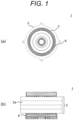
- FIG. 1(a) is a view of a rotary electric machine as viewed from an axial direction.
- FIG. 1(b) is a view of FIG. 1(a) as viewed from a radial direction.
- a rotary electric machine 1 includes a stator 2 on an outer peripheral side and a rotor 3 on an inner peripheral side. The rotor 3 faces the stator 2 with a predetermined gap (not shown) interposed therebetween.
- a stator core 2a is an electromagnetic steel plate having a plurality of slots.
- a plurality of coils 6 are arranged side by side in the radial direction and inserted into the plurality of slots provided in the stator core 2a.
- the rotor core 4 (referred to as a core 4 below) of the rotor 3 has a plurality of holes.
- magnet holes into which a plurality of magnets are respectively inserted include magnet holes into which a pair of first layer magnets 11 arranged in a V-shape are inserted, and magnet holes into which a pair of second layer magnets 12 arranged in a V-shape on an inner diameter side of the first layer magnets 11 are inserted.
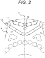
- the core 4 has a hole portion 10 at a position that overlaps with a d-axis 7, which is the magnetic pole center of the rotor core 4, between the first layer magnet 11 and the second layer magnet 12.
- the hole portion 10 is a hole for reducing stress.
- the hole portion 10 is not provided in a portion in which the density of the magnetic flux is high in the core 4, that is, on a flow path of the magnetic flux, and is provided at a position at which the magnetic performance is not affected.
- FIG. 3 (FIG. 3)
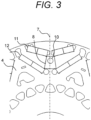
- the hole portion 10 is disposed in a region 8 formed by joining the corner on the innermost diameter side among the corners of the first layer magnets 11 and the corner closest to the d-axis 7 among the corners of the second layer magnets 12. As described above, by providing the hole portion 10 in the region 8 at the position that overlaps with the d-axis 7 between the first layer magnet hole and the second layer magnet hole, it is possible to disperse and reduce a load of stress related to the d-axis 7 on the inner side and the outer side of the core 4 in a well-balanced manner, so that it is possible to realize the stress reduction and the improvement of the rotational strength of the core 4.
- a plurality of hole portions 10 may be formed in the core 4 as long as a configuration in which the hole portions 10 are provided at positions that overlap with the d-axis 7 between the first layer magnet 11 and the second layer magnet 12, and the hole portions 10 are formed as voids is made.
- FIG. 4 (FIG. 4)
- a hole portion 10a includes a lower side that has a predetermined curvature and protrudes inward in the radial direction, and an upper side that has a curvature smaller than the predetermined curvature and protrudes outward in the radial direction.
- FIG. 5 (FIG. 5)
- a hole portion 10b includes a lower side that has a predetermined curvature and protrudes inward in the radial direction, and an upper side that has a curvature larger than the predetermined curvature and protrudes outward in the radial direction.
- the area of the hole portion 10 described with reference to FIGS. 2 and 3 is the same as the areas of the hole portions 10a and 10b described with reference to FIGS. 4 and 5 .
- the shape of the hole portion 10 does not need to be limited as long as the hole portion is provided at a place of the core 4 that does not affect the flow path of the magnetic flux and the size thereof does not affect the flow path of the magnetic flux.
- FIG. 6 (FIG. 6)
- the maximum diameter dimension d1 of the hole portion 10 is larger than the bridge width d2 formed between a pair of magnet holes into which the second layer magnets 12 are respectively inserted.
- FIG. 6 illustrates the maximum diameter dimension d1 in a direction perpendicular to the d-axis 7 in order to facilitate comparison of the width dimension.
- FIG. 7 (FIG. 7)
- a first angle ⁇ 1 formed by the first layer magnet 11 and the d-axis 7 is larger than a second angle ⁇ 2 formed by the second layer magnet 12 and the d-axis 7.
- the present invention is not limited to the above embodiment, and various modifications and other configurations can be combined without departing from the gist of the present invention.
- the present invention is not limited to one including all the configurations described in the above embodiment, and includes one in which a portion of the configuration is deleted.
Landscapes
- Engineering & Computer Science (AREA)
- Power Engineering (AREA)
- Permanent Field Magnets Of Synchronous Machinery (AREA)
Abstract
Description
- The present invention relates to a rotary electric machine.
- In a rotary electric machine, stress of a rotor core, which is generated by a rotational centrifugal force of a rotor, varies depending on the shape of a magnet hole of the rotor core. Regarding the stress of the rotor core, from the viewpoint of reliability, the maximum main stress needs to be equal to or less than the material strength of the material amount of the rotor core. In addition, in the rotor, the torque is improved in a configuration of the magnet arranged in a double V-shape as compared with a configuration of the magnet arranged in a single V-shape, and thus, it is advantageous to adopt the latter in order to improve the performance, but the stress of the rotor core increases. Based on this, the rotor core is required to achieve both improvement in torque and response to stress.
-
PTL 1 below discloses a configuration of a permanent magnet motor in which a double V-shaped magnet is arranged and a hole is provided in a portion other than a magnet insertion portion to disperse stress of a rotor core, which is generated by a centrifugal force. - PTL 1:
JP 2013-141393 A - In the configuration disclosed in
PTL 1, since there is a large hole in a d-axis portion between second layers, the magnet magnetic flux cannot be effectively used, and the performance of the motor is greatly adversely affected. In addition, the performance of the motor is deteriorated, and, at the same time, the strength is also problematic due to the stress of the rotor core caused by the rotational centrifugal force. Considering this, an object of the present invention is to provide a rotary electric machine that reduces stress without reducing torque and improves rotational strength. - A rotary electric machine includes a rotor core having a plurality of magnet holes, and a plurality of magnets respectively inserted into the plurality of magnet holes. The magnet includes a pair of first layer magnets arranged in a V-shape and a pair of second layer magnets arranged in a V-shape on an inner diameter side of the first layer magnets, and the rotor core has a hole portion at a position that overlaps with a d-axis which is a magnetic pole center of the rotor core, the hole portion being between the first layer magnet and the second layer magnet.
- According to the present invention, it is possible to provide a rotary electric machine that reduces stress without reducing torque and improves rotational strength.
-
- [
FIG. 1] FIG. 1 is an overall view of a rotary electric machine. - [
FIG. 2] FIG. 2 is an explanatory view of a hole portion of a rotor of the rotary electric machine according to an embodiment of the present invention. - [
FIG. 3] FIG. 3 is an explanatory view of a region defining a position of the hole portion inFIG. 2 . - [
FIG. 4] FIG. 4 is a first modification example. - [
FIG. 5] FIG. 5 is a second modification example. - [
FIG. 6] FIG. 6 is an explanatory view of a definition of the hole portion inFIG. 2 . - [
FIG. 7] FIG. 7 is an explanatory view of a relationship between a d-axis and a magnet hole. - Hereinafter, an embodiment of the present invention will be described with reference to the drawings. The following description and drawings are examples for describing the present invention, and will be omitted and simplified as appropriate for the sake of clarity of description. The present invention can be carried out in various other forms. Unless otherwise specified, each component may be singular or plural.
- Positions, sizes, shapes, ranges, and the like of components illustrated in the drawings may not represent actual positions, actual sizes, actual shapes, actual ranges, and the like in order to facilitate understanding of the invention. Therefore, the present invention is not necessarily limited to the positions, the sizes, the shapes, the ranges, and the like disclosed in the drawings.
-
FIG. 1(a) is a view of a rotary electric machine as viewed from an axial direction.FIG. 1(b) is a view ofFIG. 1(a) as viewed from a radial direction. A rotaryelectric machine 1 includes astator 2 on an outer peripheral side and arotor 3 on an inner peripheral side. Therotor 3 faces thestator 2 with a predetermined gap (not shown) interposed therebetween. Astator core 2a is an electromagnetic steel plate having a plurality of slots. A plurality ofcoils 6 are arranged side by side in the radial direction and inserted into the plurality of slots provided in thestator core 2a. - The rotor core 4 (referred to as a
core 4 below) of therotor 3 has a plurality of holes. Among the plurality of holes, magnet holes into which a plurality of magnets are respectively inserted include magnet holes into which a pair offirst layer magnets 11 arranged in a V-shape are inserted, and magnet holes into which a pair ofsecond layer magnets 12 arranged in a V-shape on an inner diameter side of thefirst layer magnets 11 are inserted. - The
core 4 has ahole portion 10 at a position that overlaps with a d-axis 7, which is the magnetic pole center of therotor core 4, between thefirst layer magnet 11 and thesecond layer magnet 12. Thehole portion 10 is a hole for reducing stress. Thehole portion 10 is not provided in a portion in which the density of the magnetic flux is high in thecore 4, that is, on a flow path of the magnetic flux, and is provided at a position at which the magnetic performance is not affected. - The
hole portion 10 is disposed in aregion 8 formed by joining the corner on the innermost diameter side among the corners of thefirst layer magnets 11 and the corner closest to the d-axis 7 among the corners of thesecond layer magnets 12. As described above, by providing thehole portion 10 in theregion 8 at the position that overlaps with the d-axis 7 between the first layer magnet hole and the second layer magnet hole, it is possible to disperse and reduce a load of stress related to the d-axis 7 on the inner side and the outer side of thecore 4 in a well-balanced manner, so that it is possible to realize the stress reduction and the improvement of the rotational strength of thecore 4. - Note that a plurality of
hole portions 10 may be formed in thecore 4 as long as a configuration in which thehole portions 10 are provided at positions that overlap with the d-axis 7 between thefirst layer magnet 11 and thesecond layer magnet 12, and thehole portions 10 are formed as voids is made. - A
hole portion 10a includes a lower side that has a predetermined curvature and protrudes inward in the radial direction, and an upper side that has a curvature smaller than the predetermined curvature and protrudes outward in the radial direction. As described above, by adopting thehole portion 10a having different curvatures on the outer side and the inner side in the radial direction, it is possible to disperse the load in a well-balanced manner without affecting the magnetic performance, and to further the stress reduction and the improvement of the rotational strength of thecore 4. - A
hole portion 10b includes a lower side that has a predetermined curvature and protrudes inward in the radial direction, and an upper side that has a curvature larger than the predetermined curvature and protrudes outward in the radial direction. By adopting thehole portion 10b having different curvatures on the outer side and the inner side in the radial direction as described above, it is possible to disperse the load in a well-balanced manner without affecting the magnetic performance, and to further the stress reduction and the improvement of the rotational strength of thecore 4. - Note that the area of the
hole portion 10 described with reference toFIGS. 2 and3 is the same as the areas of thehole portions FIGS. 4 and5 . In addition, even if thehole portion 10 has a shape other than thehole portions hole portion 10 does not need to be limited as long as the hole portion is provided at a place of thecore 4 that does not affect the flow path of the magnetic flux and the size thereof does not affect the flow path of the magnetic flux. - The maximum diameter dimension d1 of the
hole portion 10 is larger than the bridge width d2 formed between a pair of magnet holes into which thesecond layer magnets 12 are respectively inserted. Note thatFIG. 6 illustrates the maximum diameter dimension d1 in a direction perpendicular to the d-axis 7 in order to facilitate comparison of the width dimension. As a result, the load supported by a bridge portion crossing the d-axis 7 is reduced and deformation hardly occurs, so that it is possible to disperse the stress generated on the inner side of thecore 4 in the radial direction to the outer side in the radial direction in a better-balanced manner. - A first angle θ1 formed by the
first layer magnet 11 and the d-axis 7 is larger than a second angle θ2 formed by thesecond layer magnet 12 and the d-axis 7. With such a configuration, the effect of reducing the stress of thecore 4 by thehole portion 10 provided between thefirst layer magnet 11 and thesecond layer magnet 12 is further increased. - Although the
hole portion 10 of the present invention has been described above, since thefirst layer magnet 11 and thesecond layer magnet 12 generate heat simultaneously with the rotation of thecore 4, a configuration in which cooling water flows through thehole portion 10 to promote cooling may be adopted. - According to the embodiment of the present invention described above, the following operational effects are obtained.
- (1) The rotary
electric machine 1 includes therotor core 4 having a plurality of magnet holes, and a plurality of magnets respectively inserted into the plurality of magnet holes. The magnets include a pair offirst layer magnets 11 arranged in a V-shape, and a pair ofsecond layer magnets 12 arranged in a V-shape on an inner diameter side of thefirst layer magnets 11. Therotor core 4 has thehole portion 10 at a position that overlaps with the d-axis 7, which is the magnetic pole center of therotor core 4, between thefirst layer magnet 11 and thesecond layer magnet 12. In this manner, it is possible to provide the rotaryelectric machine 1 that reduces stress without reducing torque and improves rotational strength. - (2) The
hole portion 10 is disposed in theregion 8 formed by joining the corner on the innermost diameter side among the corners of thefirst layer magnets 11 and the corner closest to the d7-axis among the corners of thesecond layer magnets 12. In this manner, it is possible to realize the stress reduction and the improvement of the rotational strength of thecore 4. - (3) The
hole portion 10a includes the lower side that has a predetermined curvature and protrudes inward in the radial direction, and the upper side that has a curvature smaller than the predetermined curvature and protrudes outward in the radial direction. In this manner, it is possible to further realize the stress reduction and the improvement of the rotational strength of thecore 4. - (4) The
hole portion 10b includes the lower side that has a predetermined curvature and protrudes inward in the radial direction, and the upper side that has a curvature larger than the predetermined curvature and protrudes outward in the radial direction. In this manner, it is possible to further realize the stress reduction and the improvement of the rotational strength of thecore 4. - (5) The
rotor core 4 has at least onehole portion 10 at the position that overlaps with the d-axis 7 between thefirst layer magnet 11 and thesecond layer magnet 12. Thehole portion 10 is formed by at least one or more voids. In this manner, it is possible to further realize the stress reduction and the improvement of the rotational strength of thecore 4. - (6) The maximum diameter dimension d1 of the
hole portion 10 is larger than the bridge width d2 formed between a pair of magnet holes into which thesecond layer magnets 12 are respectively inserted. In this manner, it is possible to disperse the stress of thecore 4 to the outer side in the radial direction in a well-balanced manner. - (7) The first angle θ1 formed by the
first layer magnet 11 and the d-axis 7 is larger than the second angle θ2 formed by thesecond layer magnet 12 and the d-axis 7. In this manner, the effect of reducing the stress of thecore 4 is further increased. - Note that the present invention is not limited to the above embodiment, and various modifications and other configurations can be combined without departing from the gist of the present invention. In addition, the present invention is not limited to one including all the configurations described in the above embodiment, and includes one in which a portion of the configuration is deleted.
-
- 1
- rotary electric machine
- 2
- stator
- 3
- rotor
- 4
- rotor core
- 5
- slot
- 6
- coil
- 7
- d-axis
- 8
- region
- 10
- hole portion
- 10a
- hole portion in first modification example
- 10b
- hole portion in second modification example
- 11
- first layer magnet
- 12
- second layer magnet
- d1
- maximum diameter of hole portion
- d2
- bridge width
Claims (7)
- A rotary electric machine comprising:a rotor core having a plurality of magnet holes; anda plurality of magnets respectively inserted into the plurality of magnet holes,whereinthe magnet includes a pair of first layer magnets arranged in a V-shape and a pair of second layer magnets arranged in a V-shape on an inner diameter side of the first layer magnets, andthe rotor core has a hole portion at a position that overlaps with a d-axis which is a magnetic pole center of the rotor core, the hole portion being between the first layer magnet and the second layer magnet.
- The rotary electric machine according to claim 1, wherein the hole portion is disposed in a region formed by joining a corner on an innermost diameter side among corners of the first layer magnets and a corner closest to the d-axis among corners of the second layer magnets.
- The rotary electric machine according to claim 1, whereinthe hole portion includes a lower side that has a predetermined curvature and protrudes inward in a radial direction, andan upper side that has a curvature smaller than the predetermined curvature and protrudes outward in the radial direction.
- The rotary electric machine according to claim 1, whereinthe hole portion includes a lower side that has a predetermined curvature and protrudes inward in a radial direction, andan upper side that has a curvature larger than the predetermined curvature and protrudes outward in the radial direction.
- The rotary electric machine according to claim 1, whereinthe rotor core includes at least one hole portion at a position that overlaps with the d-axis, the at least one hole portion being between the first layer magnet and the second layer magnet, andthe hole portion is formed by at least one or more voids.
- The rotary electric machine according to claim 5, wherein a maximum diameter dimension of the hole portion is larger than a bridge width formed between a pair of magnet holes into which the second layer magnets are respectively inserted.
- The rotary electric machine according to claim 5, wherein a first angle formed by the first layer magnet and the d-axis is larger than a second angle formed by the second layer magnet and the d-axis.
Applications Claiming Priority (1)
| Application Number | Priority Date | Filing Date | Title |
|---|---|---|---|
| PCT/JP2022/023237 WO2023238309A1 (en) | 2022-06-09 | 2022-06-09 | Rotary electric machine |
Publications (2)
| Publication Number | Publication Date |
|---|---|
| EP4539304A1 true EP4539304A1 (en) | 2025-04-16 |
| EP4539304A4 EP4539304A4 (en) | 2026-04-01 |
Family
ID=89117760
Family Applications (1)
| Application Number | Title | Priority Date | Filing Date |
|---|---|---|---|
| EP22945811.2A Pending EP4539304A4 (en) | 2022-06-09 | 2022-06-09 | ELECTRIC LATHE |
Country Status (5)
| Country | Link |
|---|---|
| US (1) | US20250233467A1 (en) |
| EP (1) | EP4539304A4 (en) |
| JP (1) | JP7868141B2 (en) |
| CN (1) | CN118891806A (en) |
| WO (1) | WO2023238309A1 (en) |
Family Cites Families (6)
| Publication number | Priority date | Publication date | Assignee | Title |
|---|---|---|---|---|
| JP5353962B2 (en) | 2011-07-05 | 2013-11-27 | 日産自動車株式会社 | Permanent magnet type motor |
| JP6331506B2 (en) | 2014-03-12 | 2018-05-30 | 日産自動車株式会社 | Rotor structure of rotating electrical machine |
| EP3261220B1 (en) * | 2016-06-23 | 2020-08-12 | Volvo Car Corporation | Electric machine |
| JP6508168B2 (en) | 2016-11-15 | 2019-05-08 | トヨタ自動車株式会社 | Electric rotating machine |
| CN108321951B (en) * | 2018-03-16 | 2019-12-27 | 珠海格力电器股份有限公司 | Rotor structure, permanent magnet auxiliary synchronous reluctance motor and electric automobile |
| DE102018204299A1 (en) * | 2018-03-21 | 2019-09-26 | Zf Friedrichshafen Ag | Rotor of a permanent magnet excited electric machine |
-
2022
- 2022-06-09 US US18/848,774 patent/US20250233467A1/en active Pending
- 2022-06-09 WO PCT/JP2022/023237 patent/WO2023238309A1/en not_active Ceased
- 2022-06-09 CN CN202280093832.5A patent/CN118891806A/en active Pending
- 2022-06-09 JP JP2024526139A patent/JP7868141B2/en active Active
- 2022-06-09 EP EP22945811.2A patent/EP4539304A4/en active Pending
Also Published As
| Publication number | Publication date |
|---|---|
| WO2023238309A1 (en) | 2023-12-14 |
| US20250233467A1 (en) | 2025-07-17 |
| JP7868141B2 (en) | 2026-06-01 |
| CN118891806A (en) | 2024-11-01 |
| JPWO2023238309A1 (en) | 2023-12-14 |
| EP4539304A4 (en) | 2026-04-01 |
Similar Documents
| Publication | Publication Date | Title |
|---|---|---|
| US10594177B2 (en) | Rotary electric machine and rotor core manufacturing method | |
| CN102629790B (en) | Rotor for electric rotating machine | |
| JP6507273B2 (en) | Rotor for permanent magnet embedded motor and motor using the same | |
| US12519353B2 (en) | Rotor core with plurality of permanent magnets and magnet holes with bridges between magnets/magnet holes | |
| JP2012161228A (en) | Rotor for rotary electric machine | |
| CN105814773B (en) | Permanent magnet submerged motor | |
| JP7126557B2 (en) | Rotating electric machine | |
| US11411451B2 (en) | Rotor | |
| US7474028B2 (en) | Motor | |
| KR20180090476A (en) | motor | |
| US20190372411A1 (en) | Rotor and motor using same | |
| CN102810917A (en) | Switched reluctance motor | |
| JP2011147346A (en) | Electric motor | |
| US20250233467A1 (en) | Rotary Electric Machine | |
| CN106063085B (en) | Rotor | |
| US11146128B1 (en) | Squirrel-cage rotor and rotating electric machine | |
| JP2024177786A (en) | Rotating Electric Machine | |
| EP4167450A1 (en) | Electric motor | |
| JP2023102516A (en) | Rotor and rotary electric machine | |
| US20250309709A1 (en) | Rotor for rotating electrical machine | |
| US20250364856A1 (en) | Rotating Electrical Machine | |
| CN204290538U (en) | Permanent magnet embedded motor | |
| JP7593433B2 (en) | Electric motor | |
| WO2019044612A1 (en) | Electric motor | |
| WO2018159349A1 (en) | Motor, power device, and bulldozer |
Legal Events
| Date | Code | Title | Description |
|---|---|---|---|
| STAA | Information on the status of an ep patent application or granted ep patent |
Free format text: STATUS: THE INTERNATIONAL PUBLICATION HAS BEEN MADE |
|
| PUAI | Public reference made under article 153(3) epc to a published international application that has entered the european phase |
Free format text: ORIGINAL CODE: 0009012 |
|
| STAA | Information on the status of an ep patent application or granted ep patent |
Free format text: STATUS: REQUEST FOR EXAMINATION WAS MADE |
|
| 17P | Request for examination filed |
Effective date: 20250109 |
|
| AK | Designated contracting states |
Kind code of ref document: A1 Designated state(s): AL AT BE BG CH CY CZ DE DK EE ES FI FR GB GR HR HU IE IS IT LI LT LU LV MC MK MT NL NO PL PT RO RS SE SI SK SM TR |
|
| RAP3 | Party data changed (applicant data changed or rights of an application transferred) |
Owner name: ASTEMO, LTD. |
|
| DAV | Request for validation of the european patent (deleted) | ||
| DAX | Request for extension of the european patent (deleted) | ||
| A4 | Supplementary search report drawn up and despatched |
Effective date: 20260304 |
|
| RIC1 | Information provided on ipc code assigned before grant |
Ipc: H02K 1/276 20220101AFI20260226BHEP |