EP4539220A1 - Pouch-type battery cell, and method for manufacturing same - Google Patents
Pouch-type battery cell, and method for manufacturing same Download PDFInfo
- Publication number
- EP4539220A1 EP4539220A1 EP23840033.7A EP23840033A EP4539220A1 EP 4539220 A1 EP4539220 A1 EP 4539220A1 EP 23840033 A EP23840033 A EP 23840033A EP 4539220 A1 EP4539220 A1 EP 4539220A1
- Authority
- EP
- European Patent Office
- Prior art keywords
- metal
- cases
- pair
- case
- resin layer
- Prior art date
- Legal status (The legal status is an assumption and is not a legal conclusion. Google has not performed a legal analysis and makes no representation as to the accuracy of the status listed.)
- Pending
Links
Images



Classifications
-
- H—ELECTRICITY
- H01—ELECTRIC ELEMENTS
- H01M—PROCESSES OR MEANS, e.g. BATTERIES, FOR THE DIRECT CONVERSION OF CHEMICAL ENERGY INTO ELECTRICAL ENERGY
- H01M50/00—Constructional details or processes of manufacture of the non-active parts of electrochemical cells other than fuel cells, e.g. hybrid cells
- H01M50/10—Primary casings; Jackets or wrappings
- H01M50/183—Sealing members
- H01M50/19—Sealing members characterised by the material
- H01M50/191—Inorganic material
-
- B—PERFORMING OPERATIONS; TRANSPORTING
- B23—MACHINE TOOLS; METAL-WORKING NOT OTHERWISE PROVIDED FOR
- B23K—SOLDERING OR UNSOLDERING; WELDING; CLADDING OR PLATING BY SOLDERING OR WELDING; CUTTING BY APPLYING HEAT LOCALLY, e.g. FLAME CUTTING; WORKING BY LASER BEAM
- B23K26/00—Working by laser beam, e.g. welding, cutting or boring
- B23K26/20—Bonding
- B23K26/206—Laser sealing
-
- B—PERFORMING OPERATIONS; TRANSPORTING
- B23—MACHINE TOOLS; METAL-WORKING NOT OTHERWISE PROVIDED FOR
- B23K—SOLDERING OR UNSOLDERING; WELDING; CLADDING OR PLATING BY SOLDERING OR WELDING; CUTTING BY APPLYING HEAT LOCALLY, e.g. FLAME CUTTING; WORKING BY LASER BEAM
- B23K26/00—Working by laser beam, e.g. welding, cutting or boring
- B23K26/20—Bonding
- B23K26/21—Bonding by welding
- B23K26/24—Seam welding
- B23K26/244—Overlap seam welding
-
- B—PERFORMING OPERATIONS; TRANSPORTING
- B29—WORKING OF PLASTICS; WORKING OF SUBSTANCES IN A PLASTIC STATE IN GENERAL
- B29C—SHAPING OR JOINING OF PLASTICS; SHAPING OF MATERIAL IN A PLASTIC STATE, NOT OTHERWISE PROVIDED FOR; AFTER-TREATMENT OF THE SHAPED PRODUCTS, e.g. REPAIRING
- B29C53/00—Shaping by bending, folding, twisting, straightening or flattening; Apparatus therefor
- B29C53/36—Bending and joining, e.g. for making hollow articles
-
- H—ELECTRICITY
- H01—ELECTRIC ELEMENTS
- H01M—PROCESSES OR MEANS, e.g. BATTERIES, FOR THE DIRECT CONVERSION OF CHEMICAL ENERGY INTO ELECTRICAL ENERGY
- H01M10/00—Secondary cells; Manufacture thereof
- H01M10/04—Construction or manufacture in general
- H01M10/049—Processes for forming or storing electrodes in the battery container
-
- H—ELECTRICITY
- H01—ELECTRIC ELEMENTS
- H01M—PROCESSES OR MEANS, e.g. BATTERIES, FOR THE DIRECT CONVERSION OF CHEMICAL ENERGY INTO ELECTRICAL ENERGY
- H01M50/00—Constructional details or processes of manufacture of the non-active parts of electrochemical cells other than fuel cells, e.g. hybrid cells
- H01M50/10—Primary casings; Jackets or wrappings
- H01M50/102—Primary casings; Jackets or wrappings characterised by their shape or physical structure
- H01M50/105—Pouches or flexible bags
-
- H—ELECTRICITY
- H01—ELECTRIC ELEMENTS
- H01M—PROCESSES OR MEANS, e.g. BATTERIES, FOR THE DIRECT CONVERSION OF CHEMICAL ENERGY INTO ELECTRICAL ENERGY
- H01M50/00—Constructional details or processes of manufacture of the non-active parts of electrochemical cells other than fuel cells, e.g. hybrid cells
- H01M50/10—Primary casings; Jackets or wrappings
- H01M50/116—Primary casings; Jackets or wrappings characterised by the material
- H01M50/117—Inorganic material
- H01M50/119—Metals
-
- H—ELECTRICITY
- H01—ELECTRIC ELEMENTS
- H01M—PROCESSES OR MEANS, e.g. BATTERIES, FOR THE DIRECT CONVERSION OF CHEMICAL ENERGY INTO ELECTRICAL ENERGY
- H01M50/00—Constructional details or processes of manufacture of the non-active parts of electrochemical cells other than fuel cells, e.g. hybrid cells
- H01M50/10—Primary casings; Jackets or wrappings
- H01M50/116—Primary casings; Jackets or wrappings characterised by the material
- H01M50/121—Organic material
-
- H—ELECTRICITY
- H01—ELECTRIC ELEMENTS
- H01M—PROCESSES OR MEANS, e.g. BATTERIES, FOR THE DIRECT CONVERSION OF CHEMICAL ENERGY INTO ELECTRICAL ENERGY
- H01M50/00—Constructional details or processes of manufacture of the non-active parts of electrochemical cells other than fuel cells, e.g. hybrid cells
- H01M50/10—Primary casings; Jackets or wrappings
- H01M50/116—Primary casings; Jackets or wrappings characterised by the material
- H01M50/124—Primary casings; Jackets or wrappings characterised by the material having a layered structure
-
- H—ELECTRICITY
- H01—ELECTRIC ELEMENTS
- H01M—PROCESSES OR MEANS, e.g. BATTERIES, FOR THE DIRECT CONVERSION OF CHEMICAL ENERGY INTO ELECTRICAL ENERGY
- H01M50/00—Constructional details or processes of manufacture of the non-active parts of electrochemical cells other than fuel cells, e.g. hybrid cells
- H01M50/10—Primary casings; Jackets or wrappings
- H01M50/116—Primary casings; Jackets or wrappings characterised by the material
- H01M50/124—Primary casings; Jackets or wrappings characterised by the material having a layered structure
- H01M50/126—Primary casings; Jackets or wrappings characterised by the material having a layered structure comprising three or more layers
-
- H—ELECTRICITY
- H01—ELECTRIC ELEMENTS
- H01M—PROCESSES OR MEANS, e.g. BATTERIES, FOR THE DIRECT CONVERSION OF CHEMICAL ENERGY INTO ELECTRICAL ENERGY
- H01M50/00—Constructional details or processes of manufacture of the non-active parts of electrochemical cells other than fuel cells, e.g. hybrid cells
- H01M50/10—Primary casings; Jackets or wrappings
- H01M50/116—Primary casings; Jackets or wrappings characterised by the material
- H01M50/124—Primary casings; Jackets or wrappings characterised by the material having a layered structure
- H01M50/126—Primary casings; Jackets or wrappings characterised by the material having a layered structure comprising three or more layers
- H01M50/129—Primary casings; Jackets or wrappings characterised by the material having a layered structure comprising three or more layers with two or more layers of only organic material
-
- H—ELECTRICITY
- H01—ELECTRIC ELEMENTS
- H01M—PROCESSES OR MEANS, e.g. BATTERIES, FOR THE DIRECT CONVERSION OF CHEMICAL ENERGY INTO ELECTRICAL ENERGY
- H01M50/00—Constructional details or processes of manufacture of the non-active parts of electrochemical cells other than fuel cells, e.g. hybrid cells
- H01M50/10—Primary casings; Jackets or wrappings
- H01M50/131—Primary casings; Jackets or wrappings characterised by physical properties, e.g. gas permeability, size or heat resistance
- H01M50/136—Flexibility or foldability
-
- H—ELECTRICITY
- H01—ELECTRIC ELEMENTS
- H01M—PROCESSES OR MEANS, e.g. BATTERIES, FOR THE DIRECT CONVERSION OF CHEMICAL ENERGY INTO ELECTRICAL ENERGY
- H01M50/00—Constructional details or processes of manufacture of the non-active parts of electrochemical cells other than fuel cells, e.g. hybrid cells
- H01M50/10—Primary casings; Jackets or wrappings
- H01M50/172—Arrangements of electric connectors penetrating the casing
- H01M50/174—Arrangements of electric connectors penetrating the casing adapted for the shape of the cells
- H01M50/178—Arrangements of electric connectors penetrating the casing adapted for the shape of the cells for pouch or flexible bag cells
-
- B—PERFORMING OPERATIONS; TRANSPORTING
- B23—MACHINE TOOLS; METAL-WORKING NOT OTHERWISE PROVIDED FOR
- B23K—SOLDERING OR UNSOLDERING; WELDING; CLADDING OR PLATING BY SOLDERING OR WELDING; CUTTING BY APPLYING HEAT LOCALLY, e.g. FLAME CUTTING; WORKING BY LASER BEAM
- B23K2101/00—Articles made by soldering, welding or cutting
- B23K2101/36—Electric or electronic devices
-
- Y—GENERAL TAGGING OF NEW TECHNOLOGICAL DEVELOPMENTS; GENERAL TAGGING OF CROSS-SECTIONAL TECHNOLOGIES SPANNING OVER SEVERAL SECTIONS OF THE IPC; TECHNICAL SUBJECTS COVERED BY FORMER USPC CROSS-REFERENCE ART COLLECTIONS [XRACs] AND DIGESTS
- Y02—TECHNOLOGIES OR APPLICATIONS FOR MITIGATION OR ADAPTATION AGAINST CLIMATE CHANGE
- Y02E—REDUCTION OF GREENHOUSE GAS [GHG] EMISSIONS, RELATED TO ENERGY GENERATION, TRANSMISSION OR DISTRIBUTION
- Y02E60/00—Enabling technologies; Technologies with a potential or indirect contribution to GHG emissions mitigation
- Y02E60/10—Energy storage using batteries
Definitions
- a pouch type battery cell has a structure in which an electrode assembly is accommodated in a pouch type battery case and a sealing portion is provided on an edge of the battery case.
- TP thermal propagation
- An aspect of the present invention provides a pouch type battery cell, in which a sealing portion has high thermal resistance and sealing strength, and a method for manufacturing the pouch type battery cell.
- an electrode assembly may be accommodated between a pair of cases, each of which includes a first resin layer constituting the innermost layer, a second resin layer constituting the outermost layer, and a metal layer stacked between the first resin layer and the second resin layer.
- the pouch type battery cell may include a cup portion, which is provided in at least one of the pair of cases and accommodates the electrode assembly, an insulation sealing portion, at which the first resin layers of the pair of cases are sealed to each other, a folded portion, which is folded so that an edge of one case of the pair of cases surrounds an edge of the other case, and a metal sealing portion which is provided at the folded portion and at which the metal layers of the pair of cases are sealed to each other.
- the metal sealing portion may be disposed outside the insulation sealing portion.
- the metal sealing portion may include a first metal sealing portion, at which one surface of the metal layer of the other case is sealed to the metal layer of the one case, and a second metal sealing portion at which the other surface of the metal layer of the other case is sealed to the metal layer of the one case.
- the first resin layer and the second resin layer may be excluded from the metal sealing portion.
- the metal layer may include a stainless-steel material.
- a method for manufacturing a pouch type battery cell may include accommodating the electrode assembly in a cup portion formed in at least one of the pair of cases, sealing the first resin layers of the pair of cases to each other, forming a folded portion by folding an edge of one case of the pair of cases so that the edge surrounds an edge of the other case, and sealing the metal layers to each other at the folded portion.
- the first resin layers may be thermally fused to each other, and, in the sealing of the metal layers to each other, the metal layers may be welded to each other by laser.
- the laser may be emitted onto one surface, from which the second resin layer is excluded, of both outer surfaces of the folded portion.
- a pouch type battery cell 10 may include a pair of cases 100 and an electrode assembly 200 accommodated between the pair of cases 100.
- the pair of cases 100 may be sealed in a state of accommodating the electrode assembly 200 together with an electrolyte, to constitute the pouch type battery cell 10.
- a first line L1 and a second line L2 illustrated in FIG. 1 are shown as examples of lines to be folded in the hemming process.
- the first line L1 may be parallel to the full-length direction of the pouch type battery cell 10
- the second line L2 may be parallel to the full-width direction of the pouch type battery cell 10.
- Each of the first line L1 and the second line L2 may correspond to an end of the edge 120 of the other case 100B.
- the insulating sealing portion 140 may be provided to be elongated along the edge 120 of each of the pair of cases 100.
- the insulating sealing portion 140 may be connected to the first resin layer 101 in the cup portion 110.
- the electrode assembly 200 and the electrolyte in the cup portion 110 may be sealed to be in an insulated state by the insulating sealing portion 140.
- the metal sealing portion 150 may be formed by sealing the metal layers 103 of the pair of cases 100 to each other.
- the metal layers 103 of the edges 120 of the pair of cases 100 may be welded to each other to provide the metal sealing portion 150.
- each of the edges 120 of the pair of cases 100 which constitute the folded portion 130, may include an exposed region, in which the first resin layer 101 and the second resin layer 102 are excluded and the metal layer 103 is exposed to each of the inside and the outside.
- the folded portion 130 may be provided so that the exposed region of the one case 100A is folded to surround the exposed region of the other case 100B. That is, the folded portion 130 may be provided so that the metal layer 103 of the one case 100A is folded to surround the metal layer 103 of the other case 100B.
- the first resin layer 101 and the second resin layer 102 may prevent the sealing quality and strength of the metal sealing portion 150 from decreasing.
- FIG. 3 is a cross-sectional view of a pouch type battery cell according to another embodiment of the present invention.
- a cup portion 110 may not be provided in one of a pair of cases 100.
- a cup portion may not be provided in one case 100A, and the cup portion 110 may be provided in the other case 100B.
- an edge 120 of the one case 100A may be disposed on a circumference of a portion facing the cup portion 110 of the other case 100B.
- the edge 120 of the one case 100A may be folded to surround the edge 120 of the other case 100B to form a folded portion 130.
- an embodiment of the present invention is not limited thereto, and the edge 120 of the other case 100B may be also folded to surround the edge 120 of the one case 100A to form the folded portion 130.
- first resin layers 101 of the edges 120 of the pair of cases 100 may be thermally fused to each other to provide an insulating sealing portion 140, and metal layers 103 of the folded portion 130 may be welded to each other to provide a metal sealing portion 150.
- the content described above applies to sealing portions 140 and 150.
- FIG. 4 is an enlarged cross-sectional view illustrating a folded portion of a pouch type battery cell according to still another embodiment of the present invention.
- a second resin layer 102 may be excluded from any one of both outer surfaces a folded portion 130.
- the second resin layer 102 may be excluded from one surface (a top surface in FIG. 4 ), which includes an end of one case 100A, of both the outer surfaces of the folded portion 130, and the second resin layer 102 may be included in the opposite surface (a bottom surface in FIG. 4 ). That is, there is a difference in that, in the embodiment described above, the second resin layer 102 is excluded from each of both the outer surfaces of the folded portion 130, whereas in this embodiment, the second resin layer 102 is included in any one of both the outer surfaces of the folded portion 130.
- a laser beam for forming a metal sealing portion 150 may be emitted onto one surface, from which the second resin layer 102 is excluded, of both the outer surfaces of the folded portion 130. Accordingly, metal layers 103 of the folded portion 130 may be welded to each other so that damage to the second resin layer 102 is minimized during the forming of the metal sealing portion 150.
- FIG. 5 is a cross-sectional view of a pouch type battery cell according to Comparative Example.
- a pouch type battery cell 10' according to Comparative Example may include an insulating sealing portion 140, on which first resin layers 101 of edges 120 of a pair of cases 100 are thermally fused to each other, and may not include a metal sealing portion 150 on which metal layers 103 are welded to each other.
- the insulating sealing portion 140 may be weak against high-temperature.
- the first resin layers 101 include a polypropylene (PP) material
- the insulating sealing portion 140 may be melted at a temperature of about 150°C.
- PP polypropylene
- the folded portion 130 may include the metal sealing portion 150 that is dually sealed, so that the sealing of the pouch type battery cell 10 is maintained even when the insulating sealing portion 140 is melted.
- the metal sealing portion 150 may have higher sealing strength than the insulating sealing portion 140.
- the metal sealing portion 150 when the metal layer 103 constituting the metal sealing portion 150 includes a stainless steel (STS) material, the metal sealing portion 150 may not be melted to a temperature of about 1400°C and may maintain the sealing. Accordingly, an occurrence of thermal propagation (TP) to other battery cells around the pouch type battery cell 10 may be prevented or sufficiently delayed.
- STS stainless steel
- FIG. 6 is a flowchart of a method for manufacturing a pouch type battery cell according to still another embodiment of the present invention.
- the method for manufacturing a pouch type battery cell according to still another embodiment of the present invention may be a method for manufacturing the pouch type battery cell 10 described above.
- the method for manufacturing the pouch type battery cell may include accommodating an electrode assembly 200 in a cup portion 110 formed in at least one of a pair of cases 100 (S10) (hereinafter referred to as an "accommodating process"), sealing first resin layers 101 of the pair of cases 100 to each other (S20) (hereinafter referred to as an "insulation sealing process"), forming a folded portion 130 by folding an edge 120 of one case 100A of the pair of cases 100 so that the edge 120 surrounds an edge 120 of the other case 100B(S30) (hereinafter referred to as a "processing process"), and sealing metal layers 103 to each other at the folded portion 130 (S40) (hereinafter referred to as a "metal sealing process").
- the edges 120 of the pair of cases 100 may be in contact with each other in a state in which the electrode assembly 200 is accommodated in the cup portion 110. Accordingly, the electrode assembly 200 may be accommodated between the pair of cases 100.
- the first resin layers 101 of the edges 120 of the pair of cases 100 may be thermally fused to each other to form an insulating sealing portion 140.
- an exposed region of the one case 100A may be folded to surround an exposed region of the other case 100B.
- the exposed region may mean a region in which the first resin layer 101 is excluded from the edge 120 of each of the cases 100 and the metal layer 103 is exposed to the inside. Also, a second resin layer 102 may be excluded and the metal layer 103 may be exposed to the outside in at least a portion of the exposed region.
- the metal sealing portion 150 may include a first metal sealing portion 151, on which one surface (e.g., a top surface) of the metal layer 103 of the other case 100B is sealed to the metal layer 103 of the one case 100A, and a second metal sealing portion 152 on which the other surface (e.g., a bottom surface) of the metal layer 103 of the other case 100B is sealed to the metal layer 103 of the one case 100A.
- a first metal sealing portion 151 on which one surface (e.g., a top surface) of the metal layer 103 of the other case 100B is sealed to the metal layer 103 of the one case 100A
- second metal sealing portion 152 on which the other surface (e.g., a bottom surface) of the metal layer 103 of the other case 100B is sealed to the metal layer 103 of the one case 100A.
- the processing process (S30) and the metal sealing process (S40) may be performed in sequence. However, the order in which the insulation sealing process (S20) is performed may be changed as necessary.
- the insulation sealing process (S20) may be performed after the processing process (S30) and the metal sealing process (S40).
- pouch type battery cell 100 case 101: first resin layer 102: second resin layer 103: metal layer 110: cup portion 120: edge 130: folded portion 140: insulating sealing portion 150: metal sealing portion 151: first metal sealing portion 152: second metal sealing portion 200: electrode assembly
Landscapes
- Chemical & Material Sciences (AREA)
- Chemical Kinetics & Catalysis (AREA)
- Electrochemistry (AREA)
- General Chemical & Material Sciences (AREA)
- Engineering & Computer Science (AREA)
- Physics & Mathematics (AREA)
- Optics & Photonics (AREA)
- Inorganic Chemistry (AREA)
- Mechanical Engineering (AREA)
- Plasma & Fusion (AREA)
- Manufacturing & Machinery (AREA)
- Sealing Battery Cases Or Jackets (AREA)
Abstract
Description
- This application claims the priority of
Korean Patent Application No. 10-2022-0087829 filed on July 15, 2022 - The present invention relates to a pouch type battery cell, in which an electrode assembly is accommodated between a pair of cases, each of which includes a first resin layer constituting the innermost layer, a second resin layer constituting the outermost layer, and a metal layer stacked between the first resin layer and the second resin layer, and a method for manufacturing the pouch type battery cell.
- Recently, secondary batteries receive attention as power sources for electric vehicles (EV), hybrid electric vehicles (HEV), and the like, which are proposed as solutions to solve problems such as air pollution caused by existing gasoline vehicles, diesel vehicles, and the like, using fossil fuel.
- While a small-sized mobile device uses one or a few secondary batteries, a medium to large-sized device such as electric vehicle, uses a battery module, in which a plurality of secondary batteries are electrically connected to each other, or a battery pack, in which a plurality of battery modules are electrically connected to each other, due to the need for high output and large capacity.
- It can be said that one of the secondary batteries that attract the most interest among currently commercialized secondary batteries is a lithium secondary battery. According to the shape of an exterior material, the lithium secondary battery may be classified into a can type, a prismatic type, a pouch type, and the like. Among these batteries, pouch type secondary batteries are widely used in medium to large-sized battery modules due to advantages of having a high energy density and of being easily stacked.
- Recently, as a demand for a secondary battery module mounted in a vehicle increases, the customers' request for stability gradually increases. The customers request that an energy density of the battery cells be increased in a restricted space of the secondary battery module. In this case, there is a problem that a stability risk related to battery cell fires and explosions increases together.
- In general, a pouch type battery cell has a structure in which an electrode assembly is accommodated in a pouch type battery case and a sealing portion is provided on an edge of the battery case.
- When a temperature of the battery exceeds a critical temperature due to abnormal heat generation or the like, the temperature rapidly may increase and thermal propagation (TP) to other surrounding battery cells may occur. Accordingly, a safety problem may occur. Thus, a sealing portion having higher thermal resistance and sealing strength needs to be achieved to prevent or sufficiently delay the thermal propagation.
- An aspect of the present invention provides a pouch type battery cell, in which a sealing portion has high thermal resistance and sealing strength, and a method for manufacturing the pouch type battery cell.
- In a pouch type battery cell according to an embodiment of the present invention, an electrode assembly may be accommodated between a pair of cases, each of which includes a first resin layer constituting the innermost layer, a second resin layer constituting the outermost layer, and a metal layer stacked between the first resin layer and the second resin layer. The pouch type battery cell may include a cup portion, which is provided in at least one of the pair of cases and accommodates the electrode assembly, an insulation sealing portion, at which the first resin layers of the pair of cases are sealed to each other, a folded portion, which is folded so that an edge of one case of the pair of cases surrounds an edge of the other case, and a metal sealing portion which is provided at the folded portion and at which the metal layers of the pair of cases are sealed to each other.
- The metal sealing portion may be disposed outside the insulation sealing portion.
- The metal sealing portion may include a first metal sealing portion, at which one surface of the metal layer of the other case is sealed to the metal layer of the one case, and a second metal sealing portion at which the other surface of the metal layer of the other case is sealed to the metal layer of the one case.
- The first resin layer and the second resin layer may be excluded from the metal sealing portion.
- The first resin layer may be excluded from the metal sealing portion, and the second resin layer may be excluded from any one of both outer surfaces of the folded portion.
- The metal layer may include a stainless-steel material.
- A method for manufacturing a pouch type battery cell according to an embodiment of the present invention may include accommodating the electrode assembly in a cup portion formed in at least one of the pair of cases, sealing the first resin layers of the pair of cases to each other, forming a folded portion by folding an edge of one case of the pair of cases so that the edge surrounds an edge of the other case, and sealing the metal layers to each other at the folded portion.
- In the sealing of the first resin layers to each other, the first resin layers may be thermally fused to each other, and, in the sealing of the metal layers to each other, the metal layers may be welded to each other by laser.
- The edge of each of the pair of cases may include an exposed region in which the first resin layer is excluded and the metal layer is exposed to the inside, and, in the forming of the folded portion, the exposed region of the one case may surround the exposed region of the other case.
- In the sealing of the metal layers to each other, the laser may be emitted onto one surface, from which the second resin layer is excluded, of both outer surfaces of the folded portion.
- According to the preferred embodiments of the present invention, the metal sealing portion may be formed on the folded portion to maintain the sealing of the pouch type battery cell event at the high temperature and the high pressure and to have the high sealing strength. Accordingly, when the abnormal high-temperature occurs in the electrode assembly, the occurrence of the thermal propagation (TP) to other battery cells may be prevented or sufficiently delayed.
- Moreover, the insulating sealing potion may be formed inside the metal sealing portion to maintain the case to be in the state insulated from the electrode assembly and the electrolyte.
- The metal sealing portion may be dually sealed so that the sealing strength of the metal sealing portion is further increased.
- When compared to a case in which the folded portion is not formed, the ratio of the gap between the metal layers relative to the thickness of the folded portion may decrease so that the quality of the laser welding is improved.
- In addition, the effects may be included which are easily predictable by those skilled in the art from the configurations according to the preferred embodiments of the present invention.
- The following drawings attached in this specification illustrate a preferred embodiment of the present invention and function to make further understood the technical spirit of the present invention along with the detailed description of the invention. The present invention should not be construed as being limited to only the drawings. In the drawings:
-
FIG. 1 is a perspective view illustrating a case and an electrode assembly of a pouch type battery cell according to an embodiment of the present invention; -
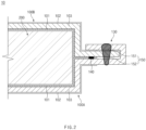
FIG. 2 is a cross-sectional view of a pouch type battery cell according to an embodiment of the present invention; -
FIG. 3 is a cross-sectional view of a pouch type battery cell according to another embodiment of the present invention; -
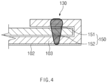
FIG. 4 is an enlarged cross-sectional view illustrating a folded portion of a pouch type battery cell according to still another embodiment of the present invention; -
FIG. 5 is a cross-sectional view of a pouch type battery cell according to Comparative Example; and -
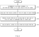
FIG. 6 is a flowchart of a method for manufacturing a pouch type battery cell according to still another embodiment of the present invention. - Hereinafter, preferred embodiments of the present invention will be described in detail with reference to the accompanying drawings to enable those skilled in the art to which the present invention pertains to easily carry out the present invention. The present invention may, however, be embodied in different forms and should not be construed as limited by the embodiments set forth herein.
- The parts unrelated to the description, or the detailed descriptions of related well-known art that may unnecessarily obscure subject matters of the present invention, will be ruled out in order to clearly describe the present invention. Like reference numerals refer to like elements throughout the whole specification.
- Moreover, terms or words used in this specification and claims should not be restrictively interpreted as ordinary meanings or dictionary-based meanings, but should be interpreted as meanings and concepts conforming to the scope of the present invention on the basis of the principle that an inventor can properly define the concept of a term to describe and explain his or her invention in the best ways.
-
FIG. 1 is a perspective view illustrating a case and an electrode assembly of a pouch type battery cell according to an embodiment of the present invention.FIG. 2 is a cross-sectional view of a pouch type battery cell according to an embodiment of the present invention. - A pouch
type battery cell 10 according to an embodiment of the present invention may include a pair ofcases 100 and anelectrode assembly 200 accommodated between the pair ofcases 100. In more detail, the pair ofcases 100 may be sealed in a state of accommodating theelectrode assembly 200 together with an electrolyte, to constitute the pouchtype battery cell 10. - The
electrode assembly 200 may include a positive electrode, a negative electrode, and a separator that is interposed between the positive electrode and the negative electrode to insulate the positive electrode and the negative electrode from each other. The type of theelectrode assembly 200 is not limited. As one example, theelectrode assembly 200 may be a stacked type electrode assembly in which a positive electrode and a negative electrode are stacked alternately with a separator therebetween. As another example, theelectrode assembly 200 may be a jelly-roll-type electrode assembly in which sheet-shaped positive and negative electrodes are wound together with a separator therebetween. - The pair of
cases 100 may provide an accommodation space capable of accommodating theelectrode assembly 200, and have a pouch shape as a whole. - The pair of
cases 100 may be connected to each other at one side, and the portions connected to each other may constitute a folding part 105. That is, the pair ofcases 100 may be connected as one body by the folding part 105. However, an embodiment of the present invention is not limited thereto, and the pair ofcases 100 may be provided as separate members separated from each other. - Each of the
cases 100 may include afirst resin layer 101, asecond resin layer 102, and ametal layer 103. That is, thecase 100 may be manufactured by molding a laminate film including thefirst resin layer 101, thesecond resin layer 102, and themetal layer 103. - The
first resin layer 101 may constitute the innermost layer of thecase 100. - The
first resin layer 101 disposed in acup portion 110 of each of the pair ofcases 100 may be in direct contact with or adjacent to each of theelectrode assembly 200 and an electrolyte. Thus, thefirst resin layer 101 may have high insulating properties and corrosion resistance. For example, thefirst resin layer 101 may include a polypropylene (PP) material. However, an embodiment of the present invention is not limited thereto, and the material of thefirst resin layer 101 may be selected as appropriate by those skilled in the art. - The first resin layers 101 disposed on
edges 120 of the pair ofcases 100, respectively, may be sealed to each other to provide an insulatingsealing portion 140. The insulatingsealing portion 140 will be described later in detail. - The
second resin layer 102 may constitute the outermost layer of thecase 100. Thesecond resin layer 102 may electrically insulate theelectrode assembly 200 from the outside while protecting the pouchtype battery cell 10 from friction and collision with the outside. For example, thesecond resin layer 102 may include a polyethylene terephthalate (PET) material. However, an embodiment of the present invention is not limited thereto, and the material of thesecond resin layer 102 may be selected as appropriate by those skilled in the art. - The
metal layer 103 may be stacked between thefirst resin layer 101 and thesecond resin layer 102. Themetal layer 103 may secure the mechanical strength of thecase 100, block entrance of external gas, moisture, or the like, and prevent leakage of the electrolyte. - The
metal layer 103 may include a stainless steel (STS) material. As the stainless steel has a melting point of about 1400°C, the stainless steel may have high thermal resistance compared to aluminum (Al) used in a pouch type battery cell according to the related art. - The metal layers 103 disposed in
edges 120 of the pair ofcases 100, respectively, may be sealed to each other to provide ametal sealing portion 150. Themetal sealing portion 150 will be described later in detail. - The
cup portion 110 that accommodates theelectrode assembly 200 may be provided in at least one of the pair ofcases 100. Thecup portion 110 may be recessed and molded in the laminate film that is a base material of thecase 100. - In this embodiment, the
cup portion 110 may be provided in each of the pair ofcases 100. The pair ofcup portions 110 may communicate with each other to provide an accommodation space in which theelectrode assembly 200 is accommodated. - Each of the pair of
cases 100 may include theedge 120 disposed at a circumference of thecup portion 110. Theedge 120 may be termed a terrace part. Theedges 120 of the pair ofcases 100 may be sealed to each other in a state of being in contact with each other and accordingly, theelectrode assembly 200 may be sealed in the pair ofcases 100. - In one example, when the pair of
cases 100 are provided as one body, the folding part 105 may be folded so that theedges 120 of the pair ofcases 100 are in contact with each other. In this case, theedges 120 that are in contact with each other may constitute three sides of the pouchtype battery cell 10, and the folding part 105 may constitute one remaining side. Thus, in the pouchtype battery cell 10, sealingportions - For another example, when the pair of
cases 100 are separated from each other, theedges 120 of the pair ofcases 100 may be disposed to be in contact with each other. In this case, theedges 120 that are in contact with each other may constitute four sides of the pouchtype battery cell 10. In the pouchtype battery cell 10, sealingportions - The pouch
type battery cell 10 may include a foldedportion 130 at which theedge 120 of onecase 100A of the pair ofcases 100 is folded to surround theedge 120 of theother case 100B. - In more detail, the
edge 120 of the onecase 100A may be processed by hemming along an end of theedge 120 of theother case 100B. To this end, theedge 120 of the onecase 100A may be wider than theedge 120 of theother case 100B. In more detail, theedge 120 of the onecase 100A may be more elongated in a full-length and full-width directions than theedge 120 of theother case 100B. - A first line L1 and a second line L2 illustrated in
FIG. 1 are shown as examples of lines to be folded in the hemming process. The first line L1 may be parallel to the full-length direction of the pouchtype battery cell 10, and the second line L2 may be parallel to the full-width direction of the pouchtype battery cell 10. Each of the first line L1 and the second line L2 may correspond to an end of theedge 120 of theother case 100B. - The first line L1 and the second line L2 may be folded in sequence or in the inverse order. A corner portion at which the first line L1 and the second line L2 overlap each other at the
edge 120 of the onecase 100A may be double folded. However, an embodiment of the present invention is not limited thereto, and the corner portion may be cut out to have an appropriate shape by those skilled in the art. - The pouch
type battery cell 10 may include the insulating sealingportion 140 and themetal sealing portion 150. - The insulating
sealing portion 140 may be formed by sealing the first resin layers 101 of the pair ofcases 100 to each other. In more detail, the first resin layers 101 of theedges 120 of the pair ofcases 100 may be thermally fused to each other to provide the insulating sealingportion 140. - The insulating
sealing portion 140 may be provided inward from the foldedportion 130 or overlap a portion of the inside of the foldedportion 130. - The insulating
sealing portion 140 may be provided to be elongated along theedge 120 of each of the pair ofcases 100. The insulatingsealing portion 140 may be connected to thefirst resin layer 101 in thecup portion 110. Thus, theelectrode assembly 200 and the electrolyte in thecup portion 110 may be sealed to be in an insulated state by the insulating sealingportion 140. - The
metal sealing portion 150 may be formed by sealing the metal layers 103 of the pair ofcases 100 to each other. In more detail, the metal layers 103 of theedges 120 of the pair ofcases 100 may be welded to each other to provide themetal sealing portion 150. - The
metal sealing portion 150 may be provided to be elongated along the foldedportion 130. Themetal sealing portion 150 may be disposed outside the insulating sealingportion 140. - As the metal layers 103 are welded to each other, the
metal sealing portion 150 may have higher sealing strength than the insulating sealingportion 140 on which the first resin layers 101 are fused to each other. Accordingly, the sealing strength of the pouchtype battery cell 10 may be remarkably increased. - The
metal sealing portion 150 may be provided at the foldedportion 130. Themetal sealing portion 150 may be formed by welding the metal layers 103 of the foldedportion 130 to each other by laser in a state in which the foldedportion 130 is formed. Thus, themetal sealing portion 150 may be dually sealed. - A laser beam for forming the
metal sealing portion 150 may be emitted at one side of the foldedportion 130, and the emitting direction is not limited. For example, the laser beam may be emitted from above or below the foldedportion 130. - In more detail, the
metal sealing portion 150 may include a firstmetal sealing portion 151, at which one surface (e.g., a top surface) of themetal layer 103 of theother case 100B is sealed to themetal layer 103 of the onecase 100A, and a secondmetal sealing portion 152 at which the other surface (e.g., a bottom surface) of themetal layer 103 of theother case 100B is sealed to themetal layer 103 of the onecase 100A. - As the
metal sealing portion 150 is dually formed at the foldedportion 130 as above, the sealing strength of the pouchtype battery cell 10 may be further increased. In addition, when compared to a case in which the foldedportion 130 is not formed, there is an advantage that a ratio of a gap between the metal layers 103 relative to the thickness of the foldedportion 130 may decrease so that quality of the laser welding is improved. - The
first resin layer 101 and thesecond resin layer 102 may be excluded from themetal sealing portion 150. - In more detail, each of the
edges 120 of the pair ofcases 100, which constitute the foldedportion 130, may include an exposed region, in which thefirst resin layer 101 and thesecond resin layer 102 are excluded and themetal layer 103 is exposed to each of the inside and the outside. The foldedportion 130 may be provided so that the exposed region of the onecase 100A is folded to surround the exposed region of theother case 100B. That is, the foldedportion 130 may be provided so that themetal layer 103 of the onecase 100A is folded to surround themetal layer 103 of theother case 100B. - Accordingly, the
first resin layer 101 and thesecond resin layer 102 may prevent the sealing quality and strength of themetal sealing portion 150 from decreasing. -
FIG. 3 is a cross-sectional view of a pouch type battery cell according to another embodiment of the present invention. - Hereinafter, the content duplicated with the embodiment described above will be omitted and the description will be focused on differences.
- In a pouch
type battery cell 10 according to another embodiment of the present invention, acup portion 110 may not be provided in one of a pair ofcases 100. For example, a cup portion may not be provided in onecase 100A, and thecup portion 110 may be provided in theother case 100B. In this case, anedge 120 of the onecase 100A may be disposed on a circumference of a portion facing thecup portion 110 of theother case 100B. - As describe above, the
edge 120 of the onecase 100A may be folded to surround theedge 120 of theother case 100B to form a foldedportion 130. However, an embodiment of the present invention is not limited thereto, and theedge 120 of theother case 100B may be also folded to surround theedge 120 of the onecase 100A to form the foldedportion 130. - In addition, first resin layers 101 of the
edges 120 of the pair ofcases 100 may be thermally fused to each other to provide an insulatingsealing portion 140, andmetal layers 103 of the foldedportion 130 may be welded to each other to provide ametal sealing portion 150. The content described above applies to sealingportions -
FIG. 4 is an enlarged cross-sectional view illustrating a folded portion of a pouch type battery cell according to still another embodiment of the present invention. - Hereinafter, the content duplicated with the embodiment described above will be omitted and the description will be focused on differences.
- In a pouch
type battery cell 10 according to still another embodiment of the present invention, asecond resin layer 102 may be excluded from any one of both outer surfaces a foldedportion 130. Preferably, thesecond resin layer 102 may be excluded from one surface (a top surface inFIG. 4 ), which includes an end of onecase 100A, of both the outer surfaces of the foldedportion 130, and thesecond resin layer 102 may be included in the opposite surface (a bottom surface inFIG. 4 ). That is, there is a difference in that, in the embodiment described above, thesecond resin layer 102 is excluded from each of both the outer surfaces of the foldedportion 130, whereas in this embodiment, thesecond resin layer 102 is included in any one of both the outer surfaces of the foldedportion 130. - A laser beam for forming a
metal sealing portion 150 may be emitted onto one surface, from which thesecond resin layer 102 is excluded, of both the outer surfaces of the foldedportion 130. Accordingly,metal layers 103 of the foldedportion 130 may be welded to each other so that damage to thesecond resin layer 102 is minimized during the forming of themetal sealing portion 150. -
FIG. 5 is a cross-sectional view of a pouch type battery cell according to Comparative Example. - A pouch type battery cell 10' according to Comparative Example may include an insulating
sealing portion 140, on which first resin layers 101 ofedges 120 of a pair ofcases 100 are thermally fused to each other, and may not include ametal sealing portion 150 on which metal layers 103 are welded to each other. - As the insulating sealing
portion 140 is formed by thermally fusing the first resin layers 101 to each other, the insulating sealingportion 140 may be weak against high-temperature. For example, when the first resin layers 101 include a polypropylene (PP) material, the insulating sealingportion 140 may be melted at a temperature of about 150°C. Thus, when a temperature exceeds a critical temperature due to abnormal heat generation of anelectrode assembly 200, or the like, the temperature rapidly increases to about 1000°C or higher. Accordingly, there is a concern that sealing of the pouch type battery cell 10' may be destroyed. - On the other hand, in the pouch
type battery cell 10 according to the present invention, the foldedportion 130 may include themetal sealing portion 150 that is dually sealed, so that the sealing of the pouchtype battery cell 10 is maintained even when the insulating sealingportion 140 is melted. Moreover, themetal sealing portion 150 may have higher sealing strength than the insulating sealingportion 140. - In particular, when the
metal layer 103 constituting themetal sealing portion 150 includes a stainless steel (STS) material, themetal sealing portion 150 may not be melted to a temperature of about 1400°C and may maintain the sealing. Accordingly, an occurrence of thermal propagation (TP) to other battery cells around the pouchtype battery cell 10 may be prevented or sufficiently delayed. -
FIG. 6 is a flowchart of a method for manufacturing a pouch type battery cell according to still another embodiment of the present invention. - The method for manufacturing a pouch type battery cell according to still another embodiment of the present invention may be a method for manufacturing the pouch
type battery cell 10 described above. - The method for manufacturing the pouch type battery cell may include accommodating an
electrode assembly 200 in acup portion 110 formed in at least one of a pair of cases 100 (S10) (hereinafter referred to as an "accommodating process"), sealing first resin layers 101 of the pair ofcases 100 to each other (S20) (hereinafter referred to as an "insulation sealing process"), forming a foldedportion 130 by folding anedge 120 of onecase 100A of the pair ofcases 100 so that theedge 120 surrounds anedge 120 of theother case 100B(S30) (hereinafter referred to as a "processing process"), and sealingmetal layers 103 to each other at the folded portion 130 (S40) (hereinafter referred to as a "metal sealing process"). - In the accommodating process (S10), the
edges 120 of the pair ofcases 100 may be in contact with each other in a state in which theelectrode assembly 200 is accommodated in thecup portion 110. Accordingly, theelectrode assembly 200 may be accommodated between the pair ofcases 100. - In the insulation sealing process (S20), the first resin layers 101 of the
edges 120 of the pair ofcases 100 may be thermally fused to each other to form an insulatingsealing portion 140. - In the processing process (S30), an exposed region of the one
case 100A may be folded to surround an exposed region of theother case 100B. The exposed region may mean a region in which thefirst resin layer 101 is excluded from theedge 120 of each of thecases 100 and themetal layer 103 is exposed to the inside. Also, asecond resin layer 102 may be excluded and themetal layer 103 may be exposed to the outside in at least a portion of the exposed region. - In addition, when a corner portion of the
edge 120 of the onecase 100A is double folded, the processing process (S30) may include a process of pressing the double-folded corner portion. Accordingly, the corner portion may be prevented from unnecessarily increasing in thickness. - In the metal sealing process (S40), the metal layers 103 of the folded
portion 130 are welded to each other by laser to form ametal sealing portion 150. In more detail, the laser may be emitted onto one surface, from which thesecond resin layer 102 is excluded, of both outer surfaces of the foldedportion 130. - The
metal sealing portion 150 may include a firstmetal sealing portion 151, on which one surface (e.g., a top surface) of themetal layer 103 of theother case 100B is sealed to themetal layer 103 of the onecase 100A, and a secondmetal sealing portion 152 on which the other surface (e.g., a bottom surface) of themetal layer 103 of theother case 100B is sealed to themetal layer 103 of the onecase 100A. - The processing process (S30) and the metal sealing process (S40) may be performed in sequence. However, the order in which the insulation sealing process (S20) is performed may be changed as necessary.
- In one example, as illustrated in
FIG. 6 , the insulation sealing process (S20), the processing process (S30), and the metal sealing process (S40) may be performed in sequence. - In another example, the insulation sealing process (S20) may be performed after the processing process (S30) and the metal sealing process (S40).
- In still another example, the insulation sealing process (S20) may be performed between the processing process (S30) and the metal sealing process (S40).
- The description of the present invention is intended to be illustrative, and various changes and modifications can be made by those of ordinary skill in the art to which the present invention pertains, without departing from the spirit and scope of the present invention as defined by the appended claims.
- Therefore, the embodiments set forth herein are to describe the technical spirit of the present invention and not to limit. The scope of the technical spirit of the present invention is not limited by the embodiments.
- Moreover, the protective scope of the present invention should be determined by reasonable interpretation of the appended claims and all technical concepts coming within the equivalency range of the present application should be interpreted to be in the scope of the right of the present application.
-
10: pouch type battery cell 100: case 101: first resin layer 102: second resin layer 103: metal layer 110: cup portion 120: edge 130: folded portion 140: insulating sealing portion 150: metal sealing portion 151: first metal sealing portion 152: second metal sealing portion 200: electrode assembly
Claims (10)
- A pouch type battery cell, in which an electrode assembly is accommodated between a pair of cases, each of which comprises a first resin layer constituting the innermost layer, a second resin layer constituting the outermost layer, and a metal layer stacked between the first resin layer and the second resin layer, the pouch type battery cell comprising:a cup portion provided in at least one of the pair of cases and configured to accommodate the electrode assembly;an insulation sealing portion at which the first resin layers of the pair of cases are sealed to each other;a folded portion folded so that an edge of one case of the pair of cases surrounds an edge of the other case; anda metal sealing portion which is provided at the folded portion and at which the metal layers of the pair of cases are sealed to each other.
- The pouch type battery cell of claim 1, wherein the metal sealing portion is disposed outside the insulation sealing portion.
- The pouch type battery cell of claim 1, wherein the metal sealing portion comprises:a first metal sealing portion at which one surface of the metal layer of the other case is sealed to the metal layer of the one case; anda second metal sealing portion at which the other surface of the metal layer of the other case is sealed to the metal layer of the one case.
- The pouch type battery cell of claim 1, wherein the first resin layer and the second resin layer are excluded from the metal sealing portion.
- The pouch type battery cell of claim 1, wherein the first resin layer is excluded from the metal sealing portion, and
the second resin layer is excluded from any one of both outer surfaces of the folded portion. - The pouch type battery cell of claim 1, wherein the metal layer comprises a stainless-steel material.
- A method for manufacturing a pouch type battery cell, in which an electrode assembly is accommodated between a pair of cases, each of which comprises the innermost first resin layer, the outermost second resin layer, and a metal layer stacked between the first resin layer and the second resin layer, the method comprising:accommodating the electrode assembly in a cup portion formed in at least one of the pair of cases;sealing the first resin layers of the pair of cases to each other;forming a folded portion by folding an edge of one case of the pair of cases so that the edge surrounds an edge of the other case; andsealing the metal layers to each other at the folded portion.
- The method of claim 7, wherein, in the sealing of the first resin layers to each other, the first resin layers are thermally fused to each other, and
in the sealing of the metal layers to each other, the metal layers are welded to each other by laser. - The method of claim 7, wherein the edge of each of the pair of cases comprises an exposed region in which the first resin layer is excluded and the metal layer is exposed to the inside,
wherein, in the forming of the folded portion, the exposed region of the one case surrounds the exposed region of the other case. - The method of claim 7, wherein, in the sealing of the metal layers to each other, the laser is emitted onto one surface, from which the second resin layer is excluded, of both outer surfaces of the folded portion.
Applications Claiming Priority (2)
| Application Number | Priority Date | Filing Date | Title |
|---|---|---|---|
| KR1020220087829A KR102655291B1 (en) | 2022-07-15 | 2022-07-15 | Pouch type battery cell and manufacturing method of the same |
| PCT/KR2023/095027 WO2024014942A1 (en) | 2022-07-15 | 2023-07-12 | Pouch-type battery cell, and method for manufacturing same |
Publications (2)
| Publication Number | Publication Date |
|---|---|
| EP4539220A1 true EP4539220A1 (en) | 2025-04-16 |
| EP4539220A4 EP4539220A4 (en) | 2025-11-12 |
Family
ID=89509256
Family Applications (1)
| Application Number | Title | Priority Date | Filing Date |
|---|---|---|---|
| EP23840033.7A Pending EP4539220A4 (en) | 2022-07-15 | 2023-07-12 | Pouch-shaped battery cell and method for its manufacture |
Country Status (7)
| Country | Link |
|---|---|
| US (1) | US12009530B2 (en) |
| EP (1) | EP4539220A4 (en) |
| JP (1) | JP2025525532A (en) |
| KR (1) | KR102655291B1 (en) |
| CN (1) | CN119631229A (en) |
| CA (1) | CA3261428A1 (en) |
| WO (1) | WO2024014942A1 (en) |
Families Citing this family (3)
| Publication number | Priority date | Publication date | Assignee | Title |
|---|---|---|---|---|
| KR20250154804A (en) * | 2024-04-22 | 2025-10-29 | 주식회사 엘지에너지솔루션 | Battery cell and manufacturing method of the same |
| KR20260027554A (en) * | 2024-08-21 | 2026-03-03 | 주식회사 엘지에너지솔루션 | Secondary battery and method of manufacturing the same |
| CN118899596A (en) * | 2024-09-29 | 2024-11-05 | 宁德时代新能源科技股份有限公司 | Solid-state battery cell and method for manufacturing the same |
Family Cites Families (22)
| Publication number | Priority date | Publication date | Assignee | Title |
|---|---|---|---|---|
| JP4341098B2 (en) | 1999-02-02 | 2009-10-07 | パナソニック株式会社 | battery |
| JP3070035U (en) | 1999-12-28 | 2000-07-14 | パイオニクス株式会社 | Casing of card type secondary battery |
| JP2004055154A (en) | 2002-07-16 | 2004-02-19 | Nissan Motor Co Ltd | Sealing structure and sealing treatment method for stacked battery |
| JP2004095217A (en) | 2002-08-29 | 2004-03-25 | Nissan Motor Co Ltd | Laminate material for battery exterior, battery and method for manufacturing the same, and assembled battery and assembled battery module |
| KR20040048295A (en) | 2002-12-02 | 2004-06-07 | 히다치 막셀 가부시키가이샤 | Battery |
| JP2005045180A (en) | 2003-07-25 | 2005-02-17 | Tdk Corp | Electrochemical element |
| KR100879893B1 (en) * | 2006-07-10 | 2009-01-21 | 주식회사 엘지화학 | Secondary battery with improved safety |
| JP5303974B2 (en) | 2008-03-14 | 2013-10-02 | 日本電気株式会社 | Assembled battery |
| KR101002468B1 (en) | 2008-07-01 | 2010-12-17 | 삼성에스디아이 주식회사 | Pouch Type Lithium Secondary Battery |
| KR101216422B1 (en) * | 2010-10-15 | 2012-12-28 | 주식회사 엘지화학 | Secondary Battery Having Sealing Portion of Improved Insulating Property |
| WO2013132673A1 (en) | 2012-03-05 | 2013-09-12 | 新日鉄住金マテリアルズ株式会社 | Resin-metal composite seal container and method for producing same |
| US20150118543A1 (en) * | 2012-05-14 | 2015-04-30 | Eig Ltd. | Pouch-type battery with improved safety by coating sealing unit with flame retardant and heat resistant resin composition prepared by mixing flame retardant material and heat resistant material to thermoplastic resin or thermosetting resin and production method thereof |
| KR101884410B1 (en) | 2012-08-07 | 2018-08-02 | 에스케이이노베이션 주식회사 | Battery pack |
| KR20140110444A (en) | 2013-03-08 | 2014-09-17 | 현대모비스 주식회사 | Combination structure of outside installation battery pack of vehicle and method thereof |
| KR102175038B1 (en) * | 2014-03-24 | 2020-11-06 | 에스케이이노베이션 주식회사 | Pouch for secondary battery having enhanced moisture-resistance property |
| KR102023736B1 (en) | 2016-01-05 | 2019-09-20 | 주식회사 엘지화학 | Pouch case, secondary battery comprising the same, and preparation method therof |
| KR102178726B1 (en) | 2016-07-29 | 2020-11-13 | 주식회사 엘지화학 | A pouch case for a secondary battery and a pouch type secondary battery |
| WO2018235516A1 (en) | 2017-06-19 | 2018-12-27 | 株式会社村田製作所 | Secondary battery |
| KR102143627B1 (en) | 2017-11-21 | 2020-08-11 | 삼성에스디아이 주식회사 | Pouch type secondary battery |
| CN111989794B (en) | 2018-04-19 | 2023-03-24 | 株式会社村田制作所 | Secondary battery |
| KR20200114385A (en) * | 2019-03-28 | 2020-10-07 | 주식회사 엘지화학 | Pouch type secondary battery and method of manufacturing the same |
| WO2022124310A1 (en) | 2020-12-07 | 2022-06-16 | 大日本印刷株式会社 | Power storage device exterior material, method for manufacturing same, and power storage device |
-
2022
- 2022-07-15 KR KR1020220087829A patent/KR102655291B1/en active Active
-
2023
- 2023-07-12 WO PCT/KR2023/095027 patent/WO2024014942A1/en not_active Ceased
- 2023-07-12 US US18/221,102 patent/US12009530B2/en active Active
- 2023-07-12 CA CA3261428A patent/CA3261428A1/en active Pending
- 2023-07-12 JP JP2025501673A patent/JP2025525532A/en active Pending
- 2023-07-12 CN CN202380052158.0A patent/CN119631229A/en active Pending
- 2023-07-12 EP EP23840033.7A patent/EP4539220A4/en active Pending
Also Published As
| Publication number | Publication date |
|---|---|
| WO2024014942A1 (en) | 2024-01-18 |
| CN119631229A (en) | 2025-03-14 |
| US12009530B2 (en) | 2024-06-11 |
| EP4539220A4 (en) | 2025-11-12 |
| KR20240010354A (en) | 2024-01-23 |
| JP2025525532A (en) | 2025-08-05 |
| KR102655291B1 (en) | 2024-04-08 |
| US20240021927A1 (en) | 2024-01-18 |
| CA3261428A1 (en) | 2025-04-24 |
Similar Documents
| Publication | Publication Date | Title |
|---|---|---|
| US12009530B2 (en) | Pouch type battery cell and method for manufacturing the same | |
| KR101264527B1 (en) | Pouch case and battery pack using the same | |
| US9196895B2 (en) | Sealed secondary battery | |
| CN103081161A (en) | Secondary battery pouch with improved stability, pouch-type secondary battery using the same, and medium-to-large-sized battery pack | |
| JP7276996B2 (en) | Battery module and battery pack containing same | |
| US12512548B2 (en) | Battery pack and device including the same | |
| EP4113733B1 (en) | Battery cell including electrode tab having stress relief portion | |
| US11296376B2 (en) | Sealed battery | |
| US20230369703A1 (en) | Battery pack and battery holder | |
| KR101913866B1 (en) | Secondary Battery Module | |
| KR102935762B1 (en) | Battery cell and battery module including the same | |
| EP4550491A1 (en) | Folding device and folding method | |
| EP4648202A1 (en) | Pouch-type battery cell | |
| KR20250154804A (en) | Battery cell and manufacturing method of the same | |
| US12614788B2 (en) | Electrochemical pouch cell for energy storage device | |
| JP7706431B2 (en) | battery | |
| US12362413B2 (en) | Battery cell, and battery module, battery pack and vehicle including the same | |
| US20230327279A1 (en) | Flame arrester and battery pack including the same | |
| US20250349952A1 (en) | Battery Module Housing for Accommodating Battery Cell Stack | |
| KR102754503B1 (en) | Battery module and device including the same | |
| KR20260068459A (en) | Secondary battery and battery box including the same | |
| KR20230073506A (en) | Secondary battery and battery module including the same | |
| KR20250028694A (en) | Battery module and battery pack including the same | |
| KR20260034495A (en) | Electrode assembly and rechargeable battery including the same | |
| KR20240152178A (en) | Pouch type battery cell |
Legal Events
| Date | Code | Title | Description |
|---|---|---|---|
| STAA | Information on the status of an ep patent application or granted ep patent |
Free format text: STATUS: THE INTERNATIONAL PUBLICATION HAS BEEN MADE |
|
| PUAI | Public reference made under article 153(3) epc to a published international application that has entered the european phase |
Free format text: ORIGINAL CODE: 0009012 |
|
| STAA | Information on the status of an ep patent application or granted ep patent |
Free format text: STATUS: REQUEST FOR EXAMINATION WAS MADE |
|
| 17P | Request for examination filed |
Effective date: 20250113 |
|
| AK | Designated contracting states |
Kind code of ref document: A1 Designated state(s): AL AT BE BG CH CY CZ DE DK EE ES FI FR GB GR HR HU IE IS IT LI LT LU LV MC ME MK MT NL NO PL PT RO RS SE SI SK SM TR |
|
| DAV | Request for validation of the european patent (deleted) | ||
| DAX | Request for extension of the european patent (deleted) | ||
| A4 | Supplementary search report drawn up and despatched |
Effective date: 20251010 |
|
| RIC1 | Information provided on ipc code assigned before grant |
Ipc: H01M 50/191 20210101AFI20251006BHEP Ipc: H01M 50/105 20210101ALI20251006BHEP Ipc: H01M 50/119 20210101ALI20251006BHEP Ipc: H01M 50/129 20210101ALI20251006BHEP Ipc: H01M 50/126 20210101ALI20251006BHEP Ipc: H01M 50/178 20210101ALI20251006BHEP Ipc: B29C 53/36 20060101ALI20251006BHEP |