EP4539204A1 - Battery module - Google Patents
Battery module Download PDFInfo
- Publication number
- EP4539204A1 EP4539204A1 EP24205795.8A EP24205795A EP4539204A1 EP 4539204 A1 EP4539204 A1 EP 4539204A1 EP 24205795 A EP24205795 A EP 24205795A EP 4539204 A1 EP4539204 A1 EP 4539204A1
- Authority
- EP
- European Patent Office
- Prior art keywords
- cell sets
- battery module
- collection
- single cells
- electrically connected
- Prior art date
- Legal status (The legal status is an assumption and is not a legal conclusion. Google has not performed a legal analysis and makes no representation as to the accuracy of the status listed.)
- Pending
Links
- 229920002799 BoPET Polymers 0.000 claims description 15
- 230000005540 biological transmission Effects 0.000 claims description 14
- 230000007704 transition Effects 0.000 claims description 11
- 230000002093 peripheral effect Effects 0.000 claims description 4
- 238000010586 diagram Methods 0.000 description 7
- 238000009434 installation Methods 0.000 description 7
- 238000003466 welding Methods 0.000 description 7
- XAGFODPZIPBFFR-UHFFFAOYSA-N aluminium Chemical compound [Al] XAGFODPZIPBFFR-UHFFFAOYSA-N 0.000 description 3
- 229910052782 aluminium Inorganic materials 0.000 description 3
- 230000000694 effects Effects 0.000 description 3
- 238000004519 manufacturing process Methods 0.000 description 3
- 238000000034 method Methods 0.000 description 3
- 229920000139 polyethylene terephthalate Polymers 0.000 description 3
- 239000005020 polyethylene terephthalate Substances 0.000 description 3
- 238000007731 hot pressing Methods 0.000 description 2
- RYGMFSIKBFXOCR-UHFFFAOYSA-N Copper Chemical compound [Cu] RYGMFSIKBFXOCR-UHFFFAOYSA-N 0.000 description 1
- 239000000853 adhesive Substances 0.000 description 1
- 230000001070 adhesive effect Effects 0.000 description 1
- 229910052802 copper Inorganic materials 0.000 description 1
- 239000010949 copper Substances 0.000 description 1
- 239000010408 film Substances 0.000 description 1
- 239000000463 material Substances 0.000 description 1
- 238000000465 moulding Methods 0.000 description 1
- -1 polyethylene terephthalate Polymers 0.000 description 1
Images


Classifications
-
- H—ELECTRICITY
- H01—ELECTRIC ELEMENTS
- H01M—PROCESSES OR MEANS, e.g. BATTERIES, FOR THE DIRECT CONVERSION OF CHEMICAL ENERGY INTO ELECTRICAL ENERGY
- H01M50/00—Constructional details or processes of manufacture of the non-active parts of electrochemical cells other than fuel cells, e.g. hybrid cells
- H01M50/20—Mountings; Secondary casings or frames; Racks, modules or packs; Suspension devices; Shock absorbers; Transport or carrying devices; Holders
- H01M50/204—Racks, modules or packs for multiple batteries or multiple cells
- H01M50/207—Racks, modules or packs for multiple batteries or multiple cells characterised by their shape
- H01M50/209—Racks, modules or packs for multiple batteries or multiple cells characterised by their shape adapted for prismatic or rectangular cells
-
- H—ELECTRICITY
- H01—ELECTRIC ELEMENTS
- H01M—PROCESSES OR MEANS, e.g. BATTERIES, FOR THE DIRECT CONVERSION OF CHEMICAL ENERGY INTO ELECTRICAL ENERGY
- H01M10/00—Secondary cells; Manufacture thereof
- H01M10/42—Methods or arrangements for servicing or maintenance of secondary cells or secondary half-cells
- H01M10/48—Accumulators combined with arrangements for measuring, testing or indicating the condition of cells, e.g. the level or density of the electrolyte
- H01M10/482—Accumulators combined with arrangements for measuring, testing or indicating the condition of cells, e.g. the level or density of the electrolyte for several batteries or cells simultaneously or sequentially
-
- H—ELECTRICITY
- H01—ELECTRIC ELEMENTS
- H01M—PROCESSES OR MEANS, e.g. BATTERIES, FOR THE DIRECT CONVERSION OF CHEMICAL ENERGY INTO ELECTRICAL ENERGY
- H01M10/00—Secondary cells; Manufacture thereof
- H01M10/42—Methods or arrangements for servicing or maintenance of secondary cells or secondary half-cells
- H01M10/48—Accumulators combined with arrangements for measuring, testing or indicating the condition of cells, e.g. the level or density of the electrolyte
- H01M10/486—Accumulators combined with arrangements for measuring, testing or indicating the condition of cells, e.g. the level or density of the electrolyte for measuring temperature
-
- H—ELECTRICITY
- H01—ELECTRIC ELEMENTS
- H01M—PROCESSES OR MEANS, e.g. BATTERIES, FOR THE DIRECT CONVERSION OF CHEMICAL ENERGY INTO ELECTRICAL ENERGY
- H01M50/00—Constructional details or processes of manufacture of the non-active parts of electrochemical cells other than fuel cells, e.g. hybrid cells
- H01M50/20—Mountings; Secondary casings or frames; Racks, modules or packs; Suspension devices; Shock absorbers; Transport or carrying devices; Holders
- H01M50/298—Mountings; Secondary casings or frames; Racks, modules or packs; Suspension devices; Shock absorbers; Transport or carrying devices; Holders characterised by the wiring of battery packs
-
- H—ELECTRICITY
- H01—ELECTRIC ELEMENTS
- H01M—PROCESSES OR MEANS, e.g. BATTERIES, FOR THE DIRECT CONVERSION OF CHEMICAL ENERGY INTO ELECTRICAL ENERGY
- H01M50/00—Constructional details or processes of manufacture of the non-active parts of electrochemical cells other than fuel cells, e.g. hybrid cells
- H01M50/50—Current conducting connections for cells or batteries
- H01M50/502—Interconnectors for connecting terminals of adjacent batteries; Interconnectors for connecting cells outside a battery casing
- H01M50/503—Interconnectors for connecting terminals of adjacent batteries; Interconnectors for connecting cells outside a battery casing characterised by the shape of the interconnectors
-
- H—ELECTRICITY
- H01—ELECTRIC ELEMENTS
- H01M—PROCESSES OR MEANS, e.g. BATTERIES, FOR THE DIRECT CONVERSION OF CHEMICAL ENERGY INTO ELECTRICAL ENERGY
- H01M50/00—Constructional details or processes of manufacture of the non-active parts of electrochemical cells other than fuel cells, e.g. hybrid cells
- H01M50/50—Current conducting connections for cells or batteries
- H01M50/502—Interconnectors for connecting terminals of adjacent batteries; Interconnectors for connecting cells outside a battery casing
- H01M50/507—Interconnectors for connecting terminals of adjacent batteries; Interconnectors for connecting cells outside a battery casing comprising an arrangement of two or more busbars within a container structure, e.g. busbar modules
-
- H—ELECTRICITY
- H01—ELECTRIC ELEMENTS
- H01M—PROCESSES OR MEANS, e.g. BATTERIES, FOR THE DIRECT CONVERSION OF CHEMICAL ENERGY INTO ELECTRICAL ENERGY
- H01M50/00—Constructional details or processes of manufacture of the non-active parts of electrochemical cells other than fuel cells, e.g. hybrid cells
- H01M50/50—Current conducting connections for cells or batteries
- H01M50/569—Constructional details of current conducting connections for detecting conditions inside cells or batteries, e.g. details of voltage sensing terminals
-
- Y—GENERAL TAGGING OF NEW TECHNOLOGICAL DEVELOPMENTS; GENERAL TAGGING OF CROSS-SECTIONAL TECHNOLOGIES SPANNING OVER SEVERAL SECTIONS OF THE IPC; TECHNICAL SUBJECTS COVERED BY FORMER USPC CROSS-REFERENCE ART COLLECTIONS [XRACs] AND DIGESTS
- Y02—TECHNOLOGIES OR APPLICATIONS FOR MITIGATION OR ADAPTATION AGAINST CLIMATE CHANGE
- Y02E—REDUCTION OF GREENHOUSE GAS [GHG] EMISSIONS, RELATED TO ENERGY GENERATION, TRANSMISSION OR DISTRIBUTION
- Y02E60/00—Enabling technologies; Technologies with a potential or indirect contribution to GHG emissions mitigation
- Y02E60/10—Energy storage using batteries
Definitions
- the present disclosure relates to the technical field of batteries, and in particular to a battery module.
- a battery of 12 V may be applied to a generator to provide a strong starting current for starting the generator, and may also assist the generator in supplying power to an electrical device when the generator is overloaded.
- Stacking a greater number of single cells in a stacking direction results in an increase in the height of the cell sets, which does not facilitate installation on an electrical device.
- a battery module in the present disclosure including: two cell sets provided back to back, poles of the cell sets extending out laterally; and a CCS assembly 100, electrically connected to each of the two cell sets, so as to realize electrical conduction between the two the cell sets, and to realize temperature and voltage collection of each of the cell sets.
- the CCS assembly is arranged along a circumferential direction of the two cell sets and extends in a stacking direction of the single cells in each of the cell sets.
- the two cell sets provided back to back allow power to be supplied through each cell set, so that the entire battery module in the present disclosure is able to provide more power supply compared to the way of supplying power with one cell set. Furthermore, as each of the cell sets takes up a respective height, the two cell sets are able to provide a larger power supply without taking up too much height space in the stacking direction of the single cells, which is more suitable for installation when the battery module is applied in an electric vehicle. Moreover, the CCS assembly is arranged along the peripheral direction of the two cell sets and extends in the stacking direction of the single cells to be adapted to the laterally extending structure of the poles of the cell sets 200, which makes full use of lateral space of the battery module.
- Labels 100 CCS assembly, 10 transmission structure, 11 support frame, 111 PET film, 112 first through-hole, 113 second through-hole, 114 connecting hole, 12 conduction unit, 121 connecting bar, 122 external connecting bar, 1221 external connecting segment, 1221a transition segment, 1121b electrical connecting segment, 1121c first projection, 1222 inner connecting segment, 1222a first branch, 13 collection unit, 131 collection wire, 132 wire harness sleeve, 20 transition bar, 21 connecting end, 211 second branch, 22 extension segment, 221 second projection, 30 connector, 40 cable tie, 50 insulating sleeve, 200 cell set, 210 single cell, 220 positive pole, 230 negative pole, 240 parallel group, 300 battery module.
- a battery module 300 including a cell contact system, CCS, assembly 100, and two cell sets 200 provided back to back.
- the two cell sets 200 are provided back to back, and poles of the cell sets 200 extend out laterally.
- the CCS assembly is electrically connected to each of the two cell sets 200, so as to realize electrical conduction between the two the cell sets 200, and to realize temperature and voltage collection of each the cell set 200.
- the CCS assembly 100 is arranged along a peripheral direction of the two cell sets 200 and extends in a stacking direction of the single cells 210 in each of the cell sets 200.
- the battery module 300 described above adopts the two cell sets 200 provided back to back to allow power to be supplied through each of the cell sets 200, so that the entire battery module 300 in the present implementation is able to provide more power supply compared to the way of supplying power with one cell set 200. Furthermore, as each of the cell sets 200 takes up a respective height, the two cell sets are able to provide a larger power supply without taking up too much height space in the stacking direction of the single cells 210, which is more suitable for installation when the battery module is applied in an electric vehicle.
- the CCS assembly 100 is arranged along the peripheral direction of the two cell sets 200 and extends in the stacking direction of the single cells 210 to be adapted to the laterally extending structure of the poles of the cell sets 200, which makes full use of lateral space of the battery module 300.
- the CCS assembly 100 in order to facilitate realizing the electrical connection between the two cell sets 200, includes two transmission structures 10 provided oppositely and an adapter bar 20, each of the transmission structures 10 is electrically connected to corresponding one of the cell sets 200, so as to realize electrical conduction as well as temperature and voltage collection within each of the two cell sets 200, and the adapter bar 20 is electrically connected to each of the two cell sets 200, so as to realize electrical conduction between the two cell sets 200.
- the entire CCS assembly 100 in the present implementation has a simpler structure and leads to a reduction in production costs compared to the way in which each of the transmission structures 10 is provided with a respective adapter structure and a respective adapter conductive block and is then connected by bolts.
- each of the transmission structures 10 includes a support frame 11, and a conduction unit 12 and a collection unit 13 which are provided on the support frame 11.
- the conduction unit 12 is electrically connected to each of the single cells 210 to realize electrical conduction within each of the cell sets 200.
- the collection unit 13 includes a plurality of collection wires 131, and an end of the collection wires 131 is electrically connected to the conduction unit 12 or configured to mount a temperature collection member. Therefore, the transmission of voltage signals and temperature signals can be realized without the use of a circuit board by setting the components for temperature and voltage collection as collection wires 131, which leads to a reduction in production costs of the entire CCS assembly 100.
- the collection wires 131 in the present implementation are smaller in size and take up less space compared to the collection solution of employing the circuit board in the prior art, so that the entire collection unit 13 is more compact and the CCS assembly 100 can be simpler in structure.
- the CCS assembly 100 further includes a connector 30.
- the transmission of electrical signals is realized through the connector 30 and a battery management system, BMS.
- BMS battery management system
- Another end of the collection wires 131 is connected to the connector 30 to transmit the temperature and voltage signals from the connector 30 to the BMS.
- an end of part of collection wires 131 may be provided with a first connecting terminal, which is configured to be in welded connection with the conduction unit 12, and an end of part of collection wires 131 may be provided with a temperature collection sensor to collect the temperature information of the single cells 210 through the temperature collection sensor.
- a diameter of each of the collection wires 131 is in a range of 0.25 mm to 0.45 mm.
- each of the collection wires 131 being set in the range allows the diameter of each of the collection wires 131 to have a certain size, thus ensuring that a welding contact area between each of the collection wires 131 and the conduction unit 12 is sufficient to meet a requirement of a peeling force at a welding point between each of the collection wires 131 and the conduction unit 12, and allows the diameter of each of the collection wires 131 to be not too large to take up a relatively large space, thus facilitating hot-press molding between the two layers of PET, polyethylene terephthalate, film 111.
- the diameter of each of the collection wires 131 is set to 0.35 mm, to ensure a size of the welding area at the welding point between each of the collection wires 131 and the conduction unit 12, and to allow the diameter of the collection wires 131 to be not too large to take up a relatively large installation space.
- the diameter of each of the collection wires 131 may be set to another value within the range of 0.2 mm to 0.45 mm as required, such as 0.25 mm, 0.3 mm, 0.4 mm, 0.45 mm, or other values, which are not limited herein.
- the support frame 11 in order to facilitate the installation of the support frame 11 with the collection unit 13 and the conduction unit 12, respectively, includes two PET films111 provided oppositely, the conduction unit 12 and part of the collection unit 13 are hot-pressed between the two PET films 111, and part of the collection unit 13 passes through the PET films 111.
- the conduction unit 12 and part of the collection unit 13 are able to be sandwiched between the two PET films 111 by the way of setting the support frame 11 as two PET films 111, which allows the connection between the collection unit 13 and the conduction unit 12 to be shielded to ensure an insulating effect.
- the way of hot-pressing the two PET films 111 improves the reliability of protecting the welding point, and has a simpler mounting process, which improves the production efficiency.
- the PET films are provided with a first through-hole 112 and a second through-hole 113
- the first through-hole 112 is configured to be mounted with the conduction unit 12 to allows the conduction unit 12 to be exposed from the first through-hole 112, thereby facilitating the welding of the conduction unit 12 and the poles of the single cells 210.
- the second through-hole 113 is configured to be passed through by the collection unit 13, so that the passed through part of the collection unit 13 is able to be connected to the connector 30.
- the collection unit 13 when mounting the collection wire 131, part of the collection wires 131 is hot-pressed between the two PET films 111, and part of the collection wires 131 passes through the PET films 111 and is then connected to the connector 30. Since the conduction unit 12 is welded with a plurality of collection wires 131, in order to facilitate the installation of all of the collection wires 131, the collection unit 13 further includes a wire harness sleeve 132 and the wire harness sleeve 132 is sleeved outside the plurality of collection wires 131, which allows the plurality of collection wires 131 to be sleeved as a whole, thereby preventing the plurality of collection wires 131 from being in a loose state so as not to affect the assembly of the entire battery module 300.
- the support frame 11 is provided with a connecting hole 114, and the CCS assembly 100 further includes at least one cable tie 40, and the at least one cable tie 40 is configured to pass through the connecting hole 114 to bind the collection wires 131 and the wire harness sleeve 132 to the support frame 11.
- the wire harness sleeve 132 and the collection wires 131 are bound to the support frame 11 by the cable tie 40, which prevents the collection wires 131 from being in a state of being placed in the messy state, avoiding affecting the assembly of the CCS assembly 100 and the cell set 200, and ensuring a neatness when the CCS assembly 100 and the cell set 200 are assembled to form the battery module 300.
- an imitation structure that is consistent with a shape of the collection wires 131 is formed on the PET films 111 when the two PET films 111 and the collection wires 131 are hot-pressed and molded.
- the conduction unit 12 includes a connecting bar 121 and an external connecting bar 122.
- the external connecting bar 122 is configured to be electrically connected to the single cell 210 at an input or an output end of the cell sets 200, and configured to be electrically conducted with an external structure.
- the connecting bar 121 is configured to realize the series-parallel connection of the single cells 210 in each of the cell sets 200 and is connected to the adapter bar 20 in series.
- the input or output of current is realized by means of the external connecting bar 122 electrically conducting with the external structure
- the single cells 210 in each of the cell sets 200 connected in series and in parallel is realized by the connecting bar 121
- the connecting bar 121 is connected to the adapter bar 20 in series, so as to realize the current conduction of one of the transmission structures 10 with the other thereof, and ultimately, it is possible to realize the series connection of the two cell sets 200, so as to enable the two cell sets 200 in series connection to provide sufficient power to an electrical device.
- the two provided cell sets 200 are able to lead to a reduction in the height in a stacking direction of the single cells 210, and thus are adapted for the installation when applied within an electric vehicle.
- the battery module includes two external connecting bars 122.
- one of the external connecting bars 122 in one of the transmission structures 10 is an input bar
- the other is an output bar.
- One of the external connecting bars is configured to input the current
- the other is configured to output the current, thereby realizing current flow between the two cell sets 200 and the external structure.
- the CCS assembly 100 is configured to realize a way of a multi-series and multi-parallel connection of the two cell sets 200, so as to allow more single cells 210 to be connected in parallel, thereby increasing the power supply capacity of the single cells 210 applied to the battery module 300.
- each of the external connecting bars 122 includes an external connecting segment 1221 and an inner connecting segment 1222 integrally provided, the external connecting segment 1221 is configured to be electrically conducted with the external structure, the inner connecting segment 1222 includes at least two first branches 1222a provided side by side, and each of the first branches 1222a is configured to be electrically connected to corresponding one of the poles of each of the single cells 210, and to be electrically connected to the collection wires 131.
- the external connecting bars 122 not only realize electrical connection with the external structure, but are also capable of realizing electrical connection with the internal single cells 210.
- each of the external connecting bars 122 includes a plurality of first branches 1222a provided side by side, the parallel connection of the plurality of single cells 210 by the external connecting bar 122 is realized when each of the first branches 1222a is electrically connected to corresponding one of the single cells 210, for example, when electrically connected to a negative pole of each of the single cells 210.
- the current is conducted to and within the single cells 210, is conducted through the positive poles of the single cells 210 to the connecting bar 121, is then conducted through the connecting bar 121 to other single cells 210 connected to the connecting bar 121, and is ultimately conducted through the adapter bar 20 to the other cell sets 200, which is then output from the other cell set 200, thereby circulating the current.
- the number of first branches 1222a is consistent with the number of single cells 210 connected in parallel.
- the external connecting segment 1221 includes a transition part 1221a and an electrical connecting part 1121b, the transition part 1221a is connected between each of the first branches 1222a and the electrical connecting part 1121b, the electrical connecting part 1121b is configured to be electrically conducted with the external structure, the transition part 1221a is parallel to the support frame 11 and perpendicular to the electrical connecting part 1121b, and the electrical connecting part 1121b is positioned on a side of the cell sets 200.
- the two external connecting bars 122 are extended in a lateral direction of the cell sets 200 by means of the electrical connecting part 1121b being perpendicular to the transition part 1221a, and are able to be positioned on the same side of the two cell sets 200, ensuring the compactness of the structure when assembled into the battery module 300.
- each end of the adapter bar 20 is electrically connected to corresponding one of the cell sets 200, respectively, and electrically connected to the collection unit 13. That is, the adapter bar 20 not only realizes the electrical conduction between the two transmission structures 10, but also directly realizes the electrical conduction of the single cells 210, which is equivalent to also having the role of the connecting bar 121, and the current from the single cells 210 is directly conducted to the other cell set 200 through the adapter bar 20, so as to enable simplicity in the structure of the entire CCS assembly 100.
- the adapter bar 20 includes two connecting ends 21, the connecting ends 21 are connected to the support frame 11, and are further configured to realize the parallel connection of at least two single cells 210.
- the connecting ends 21 include at least two second branches 211, and each of the second branches 211 is electrically connected to corresponding one of the single cells 210.
- each of the second branches 211 is in welded connection with one of the poles of corresponding one of the single cells 210, thereby realizing a parallel connection of two single cells 210 within a parallel group 240, and also realizing a series connection with the connecting bar 121.
- the CCS assembly 100 is configured to realize a power supply module with two parallel connections and four series connections.
- Each of the external connecting bars 122 includes two first branches 1222a provided side by side, which are configured to realize the parallel connection of two of the single cells 210, and each of the connecting ends 21 includes two second branches 211, which are configured to realize the parallel connection of two of the single cells 210, so that each two of the single cells 210 connected in parallel forms a parallel group 240.
- Each of the cell sets 200 includes two parallel groups 240.
- Each two of the parallel groups 240 is connected in series through the connecting bar 121, and each of the connecting bar 121 is further configured to realize the parallel connection of the two single cells 210 in each of the parallel groups 240.
- the number of single cells 210 connected in parallel in each of the parallel groups 240 may be increased.
- the adapter bar 20 further includes an extension segment 22 connected between the two connecting ends 21.
- the extension segment 22, the two external connecting bars 122, and the connector 30 are provided on a same side of the cell sets, i.e., positioned at a same end of the supporting frame 11. That is, the structures that need to be electrically connected to the external connecting structure are all provided at the same end of the support frame 11, i.e., all provided at the same side of the cell set 200, which facilitates assembly of forming the battery module 300.
- the transition part 1221a of each of the external connecting bars 122 is provided with at least one first projection 1121c
- the extension segment 22 of the adapter bar 20 is formed with at least one second projection 221
- both the first projection 1121c and the second projection 221 are extended in the stacking direction of the single cells 210.
- the extension segment 22 In a direction of the length of the extension segment 22, i.e., in a parallel direction of the two cell sets 200, it may be stretched at the first projection 1121c and the second projection 221 when the length of the single cells 210 becomes longer, and it may be compressed at the first projection 1121c and the second projection 221 when the length of the single cells 210 becomes shorter, so as to enable the CCS assembly 100 to have greater applicability.
- the CCS assembly 100 is configured to assemble two cell sets 200 with two parallel connections and four series connections, and the number of single cells 210 is relatively low, so that the amount of current flowing in the adapter bar 20 is relatively low, and the adapter bar 20 requires a relatively low overcurrent capacity.
- the adapter bar 20 is an aluminum bar, and the adapter bar 20 made of the aluminum material, compared to the way of using a copper bar, is capable of achieving the effect of reducing the cost of use due to the lower price of the aluminum bars.
- the CCS assembly 100 further includes an insulating sleeve 50, and the insulating sleeve 50 is sleeved outside the extension segment 22, so as to protect the extension segment 22 by the insulating sleeve 50, avoiding the normal use of the battery module 300 due to the electrical conduction between the extension segment 22 and other parts.
- Each of the cell sets 200 includes four single cells 210, and each two of the single cells 210 is a parallel group 240.
- the positive poles 220 of the two single cells 210 in each of the parallel groups 240 are all at a same end, and the negative poles 230 thereof are all at another same end.
- An arrangement of the positive poles 220 and the negative poles 230 of one of the two parallel groups 240 is in an opposite direction to that of the other. In this way, a series connection effect of the four parallel groups 240 is realized by the conduction of the conduction unit 12 and the adapter bar 122.
- Fig. 6 shows a schematic diagram illustrating a current direction the current in the single cells 210 in the present implementation.
Landscapes
- Chemical & Material Sciences (AREA)
- Chemical Kinetics & Catalysis (AREA)
- Electrochemistry (AREA)
- General Chemical & Material Sciences (AREA)
- Engineering & Computer Science (AREA)
- Manufacturing & Machinery (AREA)
- Battery Mounting, Suspending (AREA)
- Connection Of Batteries Or Terminals (AREA)
Abstract
Disclosed is a battery module in the present disclosure. The battery module includes: two cell sets provided back to back, poles of the cell sets extending out laterally; and a CCS assembly 100, electrically connected to each of the two cell sets, so as to realize electrical conduction between the two cell sets, and to realize temperature and voltage collection of each of the cell sets. The CCS assembly is arranged along a circumferential direction of the two cell sets and extends in a stacking direction of the single cells in each of the cell sets.
Description
- The present disclosure claims the priority of
Chinese Patent Application No. 2023113189491 filed on October 12, 2023 Chinese Patent Application No. 2023227378808 filed on October 12, 2023 - The present disclosure relates to the technical field of batteries, and in particular to a battery module.
- A battery of 12 V may be applied to a generator to provide a strong starting current for starting the generator, and may also assist the generator in supplying power to an electrical device when the generator is overloaded.
- When there are needs to increase the battery capacity of the battery of 12 V, it is usually to stack a greater number of single cells in a stacking direction of the single cells.
- Stacking a greater number of single cells in a stacking direction results in an increase in the height of the cell sets, which does not facilitate installation on an electrical device.
- Provided is a battery module in the present disclosure, including: two cell sets provided back to back, poles of the cell sets extending out laterally; and a
CCS assembly 100, electrically connected to each of the two cell sets, so as to realize electrical conduction between the two the cell sets, and to realize temperature and voltage collection of each of the cell sets. The CCS assembly is arranged along a circumferential direction of the two cell sets and extends in a stacking direction of the single cells in each of the cell sets. - The two cell sets provided back to back allow power to be supplied through each cell set, so that the entire battery module in the present disclosure is able to provide more power supply compared to the way of supplying power with one cell set. Furthermore, as each of the cell sets takes up a respective height, the two cell sets are able to provide a larger power supply without taking up too much height space in the stacking direction of the single cells, which is more suitable for installation when the battery module is applied in an electric vehicle. Moreover, the CCS assembly is arranged along the peripheral direction of the two cell sets and extends in the stacking direction of the single cells to be adapted to the laterally extending structure of the poles of the
cell sets 200, which makes full use of lateral space of the battery module. -
-
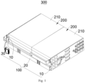
Fig. 1 is a schematic structural diagram of a battery module in an implementation of the present disclosure; -
Fig. 2 is a schematic structural diagram of a CCS assembly inFig. 1 ; -
Fig. 3 is a schematic diagram illustrating a partial exploded view of the CCS assembly inFig. 2 ; -
Fig. 4 is a schematic structural diagram of the CCS assembly inFig. 2 with a support frame being hidden; -
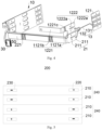
Fig. 5 is a schematic diagram illustrating a stacking method of the cell sets inFig. 1 ; and -
Fig. 6 is a schematic diagram illustrating a current direction of the CCS assembly and the cell sets in an implementation of the present disclosure. - Labels: 100 CCS assembly, 10 transmission structure, 11 support frame, 111 PET film, 112 first through-hole, 113 second through-hole, 114 connecting hole, 12 conduction unit, 121 connecting bar, 122 external connecting bar, 1221 external connecting segment, 1221a transition segment, 1121b electrical connecting segment, 1121c first projection, 1222 inner connecting segment, 1222a first branch, 13 collection unit, 131 collection wire, 132 wire harness sleeve, 20 transition bar, 21 connecting end, 211 second branch, 22 extension segment, 221 second projection, 30 connector, 40 cable tie, 50 insulating sleeve, 200 cell set, 210 single cell, 220 positive pole, 230 negative pole, 240 parallel group, 300 battery module.
- In the description of the present disclosure, it is to be noted that the terms "up", "down", "front", "back", "left", "right", "vertical", "horizontal", "top", "bottom", "inside", "outside" and other orientation or position relationships are based on the orientation or position relationships shown in the attached drawings. It is only intended to facilitate description of the present disclosure and simplify description, but not to indicate or imply that the referred device or element has a specific orientation, or is constructed and operated in a specific orientation. Therefore, they should not be construed as a limitation of the present disclosure.
- Unless otherwise defined, all terms including technical and scientific terms used herein have the same meaning as commonly understood by those skilled in the art to which the present disclosure belongs. The terms used herein in the specification of the present disclosure are used only to describe specific embodiments and are not intended as a limitation of the disclosure.
- The present disclosure is further described below in conjunction with the attached drawings.
- Referring to
Figs. 1 to 6 , provided is abattery module 300 according to the present disclosure, including a cell contact system, CCS,assembly 100, and twocell sets 200 provided back to back. - Referring to
Fig. 1 , the twocell sets 200 are provided back to back, and poles of thecell sets 200 extend out laterally. The CCS assembly is electrically connected to each of the twocell sets 200, so as to realize electrical conduction between the two thecell sets 200, and to realize temperature and voltage collection of each thecell set 200. TheCCS assembly 100 is arranged along a peripheral direction of the twocell sets 200 and extends in a stacking direction of thesingle cells 210 in each of thecell sets 200. - The
battery module 300 described above adopts the twocell sets 200 provided back to back to allow power to be supplied through each of thecell sets 200, so that theentire battery module 300 in the present implementation is able to provide more power supply compared to the way of supplying power with onecell set 200. Furthermore, as each of thecell sets 200 takes up a respective height, the two cell sets are able to provide a larger power supply without taking up too much height space in the stacking direction of thesingle cells 210, which is more suitable for installation when the battery module is applied in an electric vehicle. Moreover, theCCS assembly 100 is arranged along the peripheral direction of the twocell sets 200 and extends in the stacking direction of thesingle cells 210 to be adapted to the laterally extending structure of the poles of thecell sets 200, which makes full use of lateral space of thebattery module 300. - In some implementations, referring to
Figs. 1 to 4 , in order to facilitate realizing the electrical connection between the twocell sets 200, theCCS assembly 100 includes twotransmission structures 10 provided oppositely and anadapter bar 20, each of thetransmission structures 10 is electrically connected to corresponding one of thecell sets 200, so as to realize electrical conduction as well as temperature and voltage collection within each of the twocell sets 200, and theadapter bar 20 is electrically connected to each of the twocell sets 200, so as to realize electrical conduction between the twocell sets 200. In this way, current transfer between the external structure and the inside of the cell set 200 as well as the temperature and voltage collection are realized through thetransmission structures 10, and current transfer between the twocell sets 200 is realized through theadapter bar 20, the electrical conduction between the twocell sets 200 is realized as a whole. Theentire CCS assembly 100 in the present implementation has a simpler structure and leads to a reduction in production costs compared to the way in which each of thetransmission structures 10 is provided with a respective adapter structure and a respective adapter conductive block and is then connected by bolts. - In some implementations, each of the
transmission structures 10 includes asupport frame 11, and aconduction unit 12 and acollection unit 13 which are provided on thesupport frame 11. Theconduction unit 12 is electrically connected to each of thesingle cells 210 to realize electrical conduction within each of thecell sets 200. Thecollection unit 13 includes a plurality ofcollection wires 131, and an end of thecollection wires 131 is electrically connected to theconduction unit 12 or configured to mount a temperature collection member. Therefore, the transmission of voltage signals and temperature signals can be realized without the use of a circuit board by setting the components for temperature and voltage collection ascollection wires 131, which leads to a reduction in production costs of theentire CCS assembly 100. Furthermore, thecollection wires 131 in the present implementation are smaller in size and take up less space compared to the collection solution of employing the circuit board in the prior art, so that theentire collection unit 13 is more compact and theCCS assembly 100 can be simpler in structure. - In some implementations, the
CCS assembly 100 further includes aconnector 30. The transmission of electrical signals is realized through theconnector 30 and a battery management system, BMS. Another end of thecollection wires 131 is connected to theconnector 30 to transmit the temperature and voltage signals from theconnector 30 to the BMS. - In some implementations, in order to allow the
collection wires 131 to realize the voltage collection, an end of part ofcollection wires 131 may be provided with a first connecting terminal, which is configured to be in welded connection with theconduction unit 12, and an end of part ofcollection wires 131 may be provided with a temperature collection sensor to collect the temperature information of thesingle cells 210 through the temperature collection sensor. In some implementations, a diameter of each of thecollection wires 131 is in a range of 0.25 mm to 0.45 mm. The diameter of each of thecollection wires 131 being set in the range allows the diameter of each of thecollection wires 131 to have a certain size, thus ensuring that a welding contact area between each of thecollection wires 131 and theconduction unit 12 is sufficient to meet a requirement of a peeling force at a welding point between each of thecollection wires 131 and theconduction unit 12, and allows the diameter of each of thecollection wires 131 to be not too large to take up a relatively large space, thus facilitating hot-press molding between the two layers of PET, polyethylene terephthalate,film 111. - In some implementations, the diameter of each of the
collection wires 131 is set to 0.35 mm, to ensure a size of the welding area at the welding point between each of thecollection wires 131 and theconduction unit 12, and to allow the diameter of thecollection wires 131 to be not too large to take up a relatively large installation space. In other implementations, the diameter of each of thecollection wires 131 may be set to another value within the range of 0.2 mm to 0.45 mm as required, such as 0.25 mm, 0.3 mm, 0.4 mm, 0.45 mm, or other values, which are not limited herein. - Referring to
Fig. 3 , in an implementation of the present disclosure, in order to facilitate the installation of thesupport frame 11 with thecollection unit 13 and theconduction unit 12, respectively, thesupport frame 11 includes two PET films111 provided oppositely, theconduction unit 12 and part of thecollection unit 13 are hot-pressed between the twoPET films 111, and part of thecollection unit 13 passes through thePET films 111. In such an arrangement, theconduction unit 12 and part of thecollection unit 13 are able to be sandwiched between the twoPET films 111 by the way of setting thesupport frame 11 as twoPET films 111, which allows the connection between thecollection unit 13 and theconduction unit 12 to be shielded to ensure an insulating effect. Compared to the way of using UV adhesive to protect the welding point at the connection between thecollection unit 13 and theconduction unit 12, the way of hot-pressing the twoPET films 111 improves the reliability of protecting the welding point, and has a simpler mounting process, which improves the production efficiency. - In some implementations, the PET films are provided with a first through-
hole 112 and a second through-hole 113, the first through-hole 112 is configured to be mounted with theconduction unit 12 to allows theconduction unit 12 to be exposed from the first through-hole 112, thereby facilitating the welding of theconduction unit 12 and the poles of thesingle cells 210. The second through-hole 113 is configured to be passed through by thecollection unit 13, so that the passed through part of thecollection unit 13 is able to be connected to theconnector 30. - In some implementations, when mounting the
collection wire 131, part of thecollection wires 131 is hot-pressed between the twoPET films 111, and part of thecollection wires 131 passes through thePET films 111 and is then connected to theconnector 30. Since theconduction unit 12 is welded with a plurality ofcollection wires 131, in order to facilitate the installation of all of thecollection wires 131, thecollection unit 13 further includes awire harness sleeve 132 and thewire harness sleeve 132 is sleeved outside the plurality ofcollection wires 131, which allows the plurality ofcollection wires 131 to be sleeved as a whole, thereby preventing the plurality ofcollection wires 131 from being in a loose state so as not to affect the assembly of theentire battery module 300. - In some implementations, since the
collection wires 131 and thewire harness sleeve 132 have a certain length, in order to prevent thecollection wires 131 and theharness sleeve 132 from being in a messy state when theentire CCS assembly 100 is assembled to form thebattery module 300, thesupport frame 11 is provided with a connectinghole 114, and theCCS assembly 100 further includes at least onecable tie 40, and the at least onecable tie 40 is configured to pass through the connectinghole 114 to bind thecollection wires 131 and thewire harness sleeve 132 to thesupport frame 11. Therefore, thewire harness sleeve 132 and thecollection wires 131 are bound to thesupport frame 11 by thecable tie 40, which prevents thecollection wires 131 from being in a state of being placed in the messy state, avoiding affecting the assembly of theCCS assembly 100 and thecell set 200, and ensuring a neatness when theCCS assembly 100 and thecell set 200 are assembled to form thebattery module 300. - In some implementations, since part of the
collection wires 131 is hot-pressed between the twoPET films 111 and thePET films 111 has a certain degree of softness during hot-pressing, an imitation structure that is consistent with a shape of thecollection wires 131 is formed on thePET films 111 when the twoPET films 111 and thecollection wires 131 are hot-pressed and molded. - Referring to
Figs. 2 to 4 , shown is a structure of theconduction unit 12 in an implementation of the present disclosure. Theconduction unit 12 includes a connectingbar 121 and anexternal connecting bar 122. The external connectingbar 122 is configured to be electrically connected to thesingle cell 210 at an input or an output end of the cell sets 200, and configured to be electrically conducted with an external structure. The connectingbar 121 is configured to realize the series-parallel connection of thesingle cells 210 in each of the cell sets 200 and is connected to theadapter bar 20 in series. In this way, the input or output of current is realized by means of the external connectingbar 122 electrically conducting with the external structure, thesingle cells 210 in each of the cell sets 200 connected in series and in parallel is realized by the connectingbar 121, and the connectingbar 121 is connected to theadapter bar 20 in series, so as to realize the current conduction of one of thetransmission structures 10 with the other thereof, and ultimately, it is possible to realize the series connection of the two cell sets 200, so as to enable the two cell sets 200 in series connection to provide sufficient power to an electrical device. The two provided cell sets 200 are able to lead to a reduction in the height in a stacking direction of thesingle cells 210, and thus are adapted for the installation when applied within an electric vehicle. - In some implementations, the battery module includes two external connecting
bars 122. When one of the external connectingbars 122 in one of thetransmission structures 10 is an input bar, the other is an output bar. One of the external connecting bars is configured to input the current, and the other is configured to output the current, thereby realizing current flow between the two cell sets 200 and the external structure. - In some implementations, the
CCS assembly 100 is configured to realize a way of a multi-series and multi-parallel connection of the two cell sets 200, so as to allow moresingle cells 210 to be connected in parallel, thereby increasing the power supply capacity of thesingle cells 210 applied to thebattery module 300. - In order to facilitate the assembly of the
entire CCS assembly 100, each of the external connectingbars 122 includes an external connectingsegment 1221 and an inner connectingsegment 1222 integrally provided, the external connectingsegment 1221 is configured to be electrically conducted with the external structure, the inner connectingsegment 1222 includes at least twofirst branches 1222a provided side by side, and each of thefirst branches 1222a is configured to be electrically connected to corresponding one of the poles of each of thesingle cells 210, and to be electrically connected to thecollection wires 131. Thereby, the external connectingbars 122 not only realize electrical connection with the external structure, but are also capable of realizing electrical connection with the internalsingle cells 210. Since each of the external connectingbars 122 includes a plurality offirst branches 1222a provided side by side, the parallel connection of the plurality ofsingle cells 210 by the external connectingbar 122 is realized when each of thefirst branches 1222a is electrically connected to corresponding one of thesingle cells 210, for example, when electrically connected to a negative pole of each of thesingle cells 210. When the current is input through the external connectingbar 122, the current is conducted to and within thesingle cells 210, is conducted through the positive poles of thesingle cells 210 to the connectingbar 121, is then conducted through the connectingbar 121 to othersingle cells 210 connected to the connectingbar 121, and is ultimately conducted through theadapter bar 20 to the other cell sets 200, which is then output from the other cell set 200, thereby circulating the current. In some implementations, the number offirst branches 1222a is consistent with the number ofsingle cells 210 connected in parallel. - In order to enable a reasonable configuration of the
battery module 300 in structure when theCCS assembly 100 and the cell sets 200 are assembled into thebattery module 300, the external connectingsegment 1221 includes atransition part 1221a and an electrical connectingpart 1121b, thetransition part 1221a is connected between each of thefirst branches 1222a and the electrical connectingpart 1121b, the electrical connectingpart 1121b is configured to be electrically conducted with the external structure, thetransition part 1221a is parallel to thesupport frame 11 and perpendicular to the electrical connectingpart 1121b, and the electrical connectingpart 1121b is positioned on a side of the cell sets 200. In this way, the two external connectingbars 122 are extended in a lateral direction of the cell sets 200 by means of the electrical connectingpart 1121b being perpendicular to thetransition part 1221a, and are able to be positioned on the same side of the two cell sets 200, ensuring the compactness of the structure when assembled into thebattery module 300. - In some implementations, in order to save the cost of the
entire CCS assembly 100, each end of theadapter bar 20 is electrically connected to corresponding one of the cell sets 200, respectively, and electrically connected to thecollection unit 13. That is, theadapter bar 20 not only realizes the electrical conduction between the twotransmission structures 10, but also directly realizes the electrical conduction of thesingle cells 210, which is equivalent to also having the role of the connectingbar 121, and the current from thesingle cells 210 is directly conducted to the other cell set 200 through theadapter bar 20, so as to enable simplicity in the structure of theentire CCS assembly 100. - In some implementations, the
adapter bar 20 includes two connecting ends 21, the connecting ends 21 are connected to thesupport frame 11, and are further configured to realize the parallel connection of at least twosingle cells 210. Corresponding to the number ofsingle cells 210 in corresponding one of the cell sets 200, the connecting ends 21 include at least twosecond branches 211, and each of thesecond branches 211 is electrically connected to corresponding one of thesingle cells 210. In some implementations, each of thesecond branches 211 is in welded connection with one of the poles of corresponding one of thesingle cells 210, thereby realizing a parallel connection of twosingle cells 210 within aparallel group 240, and also realizing a series connection with the connectingbar 121. - In some implementations, referring to
Figs. 5 and6 , theCCS assembly 100 is configured to realize a power supply module with two parallel connections and four series connections. Each of the external connectingbars 122 includes twofirst branches 1222a provided side by side, which are configured to realize the parallel connection of two of thesingle cells 210, and each of the connecting ends 21 includes twosecond branches 211, which are configured to realize the parallel connection of two of thesingle cells 210, so that each two of thesingle cells 210 connected in parallel forms aparallel group 240. Each of the cell sets 200 includes twoparallel groups 240. Each two of theparallel groups 240 is connected in series through the connectingbar 121, and each of the connectingbar 121 is further configured to realize the parallel connection of the twosingle cells 210 in each of theparallel groups 240. When it is necessary to increase the amount of power supply from the cell sets 200, the number ofsingle cells 210 connected in parallel in each of theparallel groups 240 may be increased. - In some implementations, in order to ensure the compactness when assembled into the
battery module 300, theadapter bar 20 further includes anextension segment 22 connected between the two connecting ends 21. Theextension segment 22, the two external connectingbars 122, and theconnector 30 are provided on a same side of the cell sets, i.e., positioned at a same end of the supportingframe 11. That is, the structures that need to be electrically connected to the external connecting structure are all provided at the same end of thesupport frame 11, i.e., all provided at the same side of the cell set 200, which facilitates assembly of forming thebattery module 300. - In some implementations, in order to improve the applicability of the entire CCS assembly, the
transition part 1221a of each of the external connectingbars 122 is provided with at least onefirst projection 1121c, theextension segment 22 of theadapter bar 20 is formed with at least onesecond projection 221, and both thefirst projection 1121c and thesecond projection 221 are extended in the stacking direction of thesingle cells 210. Thereby, by providing thefirst projection 1121c and thesecond projection 221, theCCS assembly 100, when mounted on the two cell sets 200, is able to be compressed at the two kinds of projections, which is adapted to the assembly tolerance, and is able to be adapted to more types of thesingle cells 210. In a direction of the length of theextension segment 22, i.e., in a parallel direction of the two cell sets 200, it may be stretched at thefirst projection 1121c and thesecond projection 221 when the length of thesingle cells 210 becomes longer, and it may be compressed at thefirst projection 1121c and thesecond projection 221 when the length of thesingle cells 210 becomes shorter, so as to enable theCCS assembly 100 to have greater applicability. - In some implementations, the
CCS assembly 100 is configured to assemble two cell sets 200 with two parallel connections and four series connections, and the number ofsingle cells 210 is relatively low, so that the amount of current flowing in theadapter bar 20 is relatively low, and theadapter bar 20 requires a relatively low overcurrent capacity. Theadapter bar 20 is an aluminum bar, and theadapter bar 20 made of the aluminum material, compared to the way of using a copper bar, is capable of achieving the effect of reducing the cost of use due to the lower price of the aluminum bars. - In some implementations, in order to ensure normal use when the
CCS assembly 100 and the cell set 200 are assembled into thebattery module 300, theCCS assembly 100 further includes an insulatingsleeve 50, and the insulatingsleeve 50 is sleeved outside theextension segment 22, so as to protect theextension segment 22 by the insulatingsleeve 50, avoiding the normal use of thebattery module 300 due to the electrical conduction between theextension segment 22 and other parts. - Referring to
Fig. 5 , shown is a stacking method of the cell sets 200 in the present implementation. Each of the cell sets 200 includes foursingle cells 210, and each two of thesingle cells 210 is aparallel group 240. Thepositive poles 220 of the twosingle cells 210 in each of theparallel groups 240 are all at a same end, and thenegative poles 230 thereof are all at another same end. An arrangement of thepositive poles 220 and thenegative poles 230 of one of the twoparallel groups 240 is in an opposite direction to that of the other. In this way, a series connection effect of the fourparallel groups 240 is realized by the conduction of theconduction unit 12 and theadapter bar 122.Fig. 6 shows a schematic diagram illustrating a current direction the current in thesingle cells 210 in the present implementation.
Claims (14)
- A battery module (300), comprising:two cell sets (200) provided back to back, poles of the cell sets (200) extending out laterally; anda CCS assembly (100), electrically connected to each of the two cell sets (200), so as to realize electrical conduction between the two cell sets (200), and to realize temperature and voltage collection of each of the cell sets (200), wherein the CCS assembly (100) is arranged along a peripheral direction of the two cell sets (200) and extends in a stacking direction of single cells (210) in each of the cell sets (200).
- The battery module (300) according to claim 1, wherein the CCS assembly (100) comprises two transmission structures (10) provided oppositely and an adapter bar (20), each transmission structure (10) is electrically connected to corresponding one of the cell sets (200), so as to realize electrical conduction as well as temperature and voltage collection in each of the cell sets (200), and the adapter bar (20) is electrically connected to each of the two cell sets (200), so as to realize electrical conduction between the two cell sets (200).
- The battery module (300) according to claim 2, wherein the transmission structure (10) comprises a supporting frame (11) and a conduction unit (12) and a collection unit (13) provided on the support frame (11), wherein the conduction unit (12) is electrically connected to each of the single cells (210), so as to realize electrical conduction in the cell sets (200), the collection unit (13) comprises a plurality of collection wires (131), an end of the plurality of collection wires (131) is electrically connected to the conduction unit (12) or is configured to mount a temperature collection member.
- The battery module (300) according to claim 3, wherein a diameter of each of the plurality of collection wires (131) is in a range of 0.25 mm to 0.45 mm.
- The battery module (300) according to claim 3 or 4, wherein the collection unit (13) further comprises a wire harness sleeve (132), and the wire harness sleeve (132) is sleeved outside the plurality of the collection wires (131).
- The battery module (300) according to claim 5, wherein the support frame (11) is provided with a connecting hole (114), the CCS assembly (100) further comprises at least one cable tie (40), and the at least one cable tie (40) is configured to be passed through the connecting hole (114) to bind the collection wires (131) and the wire harness sleeve (132) to the support frame (11).
- The battery module (300) according to claim 3 or 4, wherein the conduction unit (12) comprises a connecting bar (121) and an external connecting bar (122), the external connecting bar (122) is configured to be electrically connected to the single cell (210) at an input or an output of one of the cell sets (200), and is configured to be electrically conducted with an external structure, the connecting bar (121) is configured to realize that the single cells (210) in each of the cell sets (200) are connected in series and in parallel, and the connecting bar (121) is connected to the adapter bar (20) in series.
- The battery module (300) according to claim 7, wherein the external connecting bar (122) comprises an external connecting segment (1221) and an inner connecting segment (1222) integrally provided, the external connecting segment (1221) is configured to be electrically conducted with the external structure, the inner connecting segment (1222) comprises at least two first branches (1222a) provided side by side, each of the first branches (1222a) is configured to be electrically connected to one of the poles of corresponding one of the single cells (210), and to be electrically connected to the plurality of collection wires (131).
- The battery module (300) according to claim 8, wherein the external connecting segment (1221) comprises a transition part (1221a) and an electrical connecting part (1121b), the transition part (1221a) is connected between each of the first branches (1222a) and the electrical connecting part (1121b), the electrical connecting part (1121b) is configured to be electrically conducted with the external structure, the transition part (1221a) is parallel to the support frame (11) and perpendicular to the electrical connecting part (1121b), and the electrical connecting part (1121b) is positioned on a side of the cell sets (200).
- The battery module (300) according to claim 9, wherein the adapter bar (20) comprises two connecting ends (21), the connecting ends (21) are connected to the support frame (11), and further configured to realize parallel connection of at least two of the single cells (210), the connecting ends (21) comprise at least two second branches (211), and each of the second branches (211) is electrically connected to corresponding one of the single cells (210).
- The battery module (300) according to claim 10, wherein the adapter bar (20) further comprises an extension segment (22) connected between the two connecting ends (21), and the extension segment (22), the two external connecting bars (122), and a connector (30) are provided on a same side of the cell sets (200).
- The battery module (300) according to claim 11, wherein the transition part (1221a) is provided with at least one first projection (1121c), the extension segment (22) is formed with at least one second projection (221), and both the first projection (1121c) and the second projection (221) are extended in a stacking direction of the single cells (210).
- The battery module (300) according to claim 11, wherein the CCS assembly (100) further comprises an insulating sleeve (50), and the insulating sleeve (50) is sleeved outside the extension segment (22).
- The battery module (300) according to any one of claims 3, 4, and 8-13, wherein the support frame (11) comprises two PET films (111) provided oppositely, the conduction unit (12) and part of the collection wires (131) is hot-pressed between the two PET films (111).
Applications Claiming Priority (2)
| Application Number | Priority Date | Filing Date | Title |
|---|---|---|---|
| CN202311318949.1A CN117175125A (en) | 2023-10-12 | 2023-10-12 | battery module |
| CN202322737880.8U CN221102306U (en) | 2023-10-12 | 2023-10-12 | Battery Module |
Publications (1)
| Publication Number | Publication Date |
|---|---|
| EP4539204A1 true EP4539204A1 (en) | 2025-04-16 |
Family
ID=93100121
Family Applications (1)
| Application Number | Title | Priority Date | Filing Date |
|---|---|---|---|
| EP24205795.8A Pending EP4539204A1 (en) | 2023-10-12 | 2024-10-10 | Battery module |
Country Status (4)
| Country | Link |
|---|---|
| US (1) | US20250125432A1 (en) |
| EP (1) | EP4539204A1 (en) |
| JP (1) | JP2025537453A (en) |
| WO (1) | WO2025077650A1 (en) |
Citations (4)
| Publication number | Priority date | Publication date | Assignee | Title |
|---|---|---|---|---|
| US20090017366A1 (en) * | 2006-01-03 | 2009-01-15 | Johnson Controls Technology Company | Battery system |
| US20100047682A1 (en) * | 2007-03-01 | 2010-02-25 | Johnson Controls - SAFT Advanced Power Solutions, LLC | Battery system and thermal management system therefor |
| US9450219B2 (en) * | 2011-09-15 | 2016-09-20 | Samsung Sdi Co., Ltd. | Battery module |
| US20210126310A1 (en) * | 2018-12-30 | 2021-04-29 | Contemporary Amperex Technology Co., Limited | Battery module and battery pack |
Family Cites Families (9)
| Publication number | Priority date | Publication date | Assignee | Title |
|---|---|---|---|---|
| JP4440548B2 (en) * | 2002-02-13 | 2010-03-24 | パナソニック株式会社 | Battery and manufacturing method thereof |
| CN202495496U (en) * | 2012-01-13 | 2012-10-17 | 深圳市沃特玛电池有限公司 | Stacked battery pack |
| CN211376883U (en) * | 2019-12-30 | 2020-08-28 | 银隆新能源股份有限公司 | Double-row battery module and energy storage system |
| JP2022014716A (en) * | 2020-07-07 | 2022-01-20 | トヨタ自動車株式会社 | Battery module |
| CN114583401B (en) * | 2020-12-02 | 2024-07-02 | 莫仕连接器(成都)有限公司 | Battery connection module |
| CN219476774U (en) * | 2022-12-13 | 2023-08-04 | 湖北亿纬动力有限公司 | Integrated CCS assembly and battery pack |
| CN219017875U (en) * | 2023-01-30 | 2023-05-12 | 宁德时代新能源科技股份有限公司 | Batteries and Consumers |
| CN117175125A (en) * | 2023-10-12 | 2023-12-05 | 惠州亿纬锂能股份有限公司 | battery module |
| CN221102306U (en) * | 2023-10-12 | 2024-06-07 | 惠州亿纬锂能股份有限公司 | Battery Module |
-
2024
- 2024-09-30 JP JP2024574805A patent/JP2025537453A/en active Pending
- 2024-09-30 WO PCT/CN2024/122895 patent/WO2025077650A1/en active Pending
- 2024-10-10 US US18/911,303 patent/US20250125432A1/en active Pending
- 2024-10-10 EP EP24205795.8A patent/EP4539204A1/en active Pending
Patent Citations (4)
| Publication number | Priority date | Publication date | Assignee | Title |
|---|---|---|---|---|
| US20090017366A1 (en) * | 2006-01-03 | 2009-01-15 | Johnson Controls Technology Company | Battery system |
| US20100047682A1 (en) * | 2007-03-01 | 2010-02-25 | Johnson Controls - SAFT Advanced Power Solutions, LLC | Battery system and thermal management system therefor |
| US9450219B2 (en) * | 2011-09-15 | 2016-09-20 | Samsung Sdi Co., Ltd. | Battery module |
| US20210126310A1 (en) * | 2018-12-30 | 2021-04-29 | Contemporary Amperex Technology Co., Limited | Battery module and battery pack |
Also Published As
| Publication number | Publication date |
|---|---|
| US20250125432A1 (en) | 2025-04-17 |
| JP2025537453A (en) | 2025-11-18 |
| WO2025077650A1 (en) | 2025-04-17 |
Similar Documents
| Publication | Publication Date | Title |
|---|---|---|
| KR102595362B1 (en) | Battery packs and vehicles | |
| KR102059612B1 (en) | Interconnection Member Occupying Small Space in Battery Module and Battery Module with the Same | |
| CN209401936U (en) | A kind of busbar connector and battery modules | |
| CN210006811U (en) | Battery packs for cells, battery packs and vehicles | |
| WO2022065647A1 (en) | Ffc busbar | |
| CN221102306U (en) | Battery Module | |
| CN212323159U (en) | Battery package high-voltage circuit connecting device | |
| KR20260042097A (en) | Sensing assembly and battery module including the same | |
| US20250125432A1 (en) | Battery module | |
| CN215342766U (en) | A square battery module | |
| US20250087768A1 (en) | Battery pack and electric vehicle | |
| CN109920961B (en) | Battery binding post mechanism, power battery system and electric vehicle | |
| CN211828986U (en) | Battery box | |
| CN117175125A (en) | battery module | |
| CN217213070U (en) | Battery pack temperature and voltage acquisition device | |
| CN206893696U (en) | Cylinder manifold and the battery modules containing it | |
| CN217282317U (en) | Direct current convergence device and lithium battery energy storage system | |
| CN223309165U (en) | CCS component for multi-cell module of power battery | |
| CN222775473U (en) | Battery module, battery pack and new energy automobile | |
| EP4398410A1 (en) | Battery module | |
| CN219123359U (en) | Battery module and power supply device | |
| CN216928303U (en) | Controller structure and thin film capacitor group thereof | |
| US20240145874A1 (en) | Battery module and battery with such battery modules | |
| CN220628126U (en) | Cell components, battery modules and battery packs | |
| CN220106990U (en) | New energy integrated busbar production line structure |
Legal Events
| Date | Code | Title | Description |
|---|---|---|---|
| PUAI | Public reference made under article 153(3) epc to a published international application that has entered the european phase |
Free format text: ORIGINAL CODE: 0009012 |
|
| STAA | Information on the status of an ep patent application or granted ep patent |
Free format text: STATUS: REQUEST FOR EXAMINATION WAS MADE |
|
| 17P | Request for examination filed |
Effective date: 20241010 |
|
| AK | Designated contracting states |
Kind code of ref document: A1 Designated state(s): AL AT BE BG CH CY CZ DE DK EE ES FI FR GB GR HR HU IE IS IT LI LT LU LV MC ME MK MT NL NO PL PT RO RS SE SI SK SM TR |