EP4539123A1 - Display panel and display terminal - Google Patents
Display panel and display terminal Download PDFInfo
- Publication number
- EP4539123A1 EP4539123A1 EP22927585.4A EP22927585A EP4539123A1 EP 4539123 A1 EP4539123 A1 EP 4539123A1 EP 22927585 A EP22927585 A EP 22927585A EP 4539123 A1 EP4539123 A1 EP 4539123A1
- Authority
- EP
- European Patent Office
- Prior art keywords
- line section
- section
- fan
- sections
- display panel
- Prior art date
- Legal status (The legal status is an assumption and is not a legal conclusion. Google has not performed a legal analysis and makes no representation as to the accuracy of the status listed.)
- Pending
Links
Images



Classifications
-
- H—ELECTRICITY
- H10—SEMICONDUCTOR DEVICES; ELECTRIC SOLID-STATE DEVICES NOT OTHERWISE PROVIDED FOR
- H10D—INORGANIC ELECTRIC SEMICONDUCTOR DEVICES
- H10D86/00—Integrated devices formed in or on insulating or conducting substrates, e.g. formed in silicon-on-insulator [SOI] substrates or on stainless steel or glass substrates
- H10D86/40—Integrated devices formed in or on insulating or conducting substrates, e.g. formed in silicon-on-insulator [SOI] substrates or on stainless steel or glass substrates characterised by multiple TFTs
- H10D86/441—Interconnections, e.g. scanning lines
- H10D86/443—Interconnections, e.g. scanning lines adapted for preventing breakage, peeling or short circuiting
-
- H—ELECTRICITY
- H10—SEMICONDUCTOR DEVICES; ELECTRIC SOLID-STATE DEVICES NOT OTHERWISE PROVIDED FOR
- H10D—INORGANIC ELECTRIC SEMICONDUCTOR DEVICES
- H10D86/00—Integrated devices formed in or on insulating or conducting substrates, e.g. formed in silicon-on-insulator [SOI] substrates or on stainless steel or glass substrates
- H10D86/40—Integrated devices formed in or on insulating or conducting substrates, e.g. formed in silicon-on-insulator [SOI] substrates or on stainless steel or glass substrates characterised by multiple TFTs
- H10D86/60—Integrated devices formed in or on insulating or conducting substrates, e.g. formed in silicon-on-insulator [SOI] substrates or on stainless steel or glass substrates characterised by multiple TFTs wherein the TFTs are in active matrices
-
- H—ELECTRICITY
- H10—SEMICONDUCTOR DEVICES; ELECTRIC SOLID-STATE DEVICES NOT OTHERWISE PROVIDED FOR
- H10K—ORGANIC ELECTRIC SOLID-STATE DEVICES
- H10K59/00—Integrated devices, or assemblies of multiple devices, comprising at least one organic light-emitting element covered by group H10K50/00
- H10K59/10—OLED displays
- H10K59/12—Active-matrix OLED [AMOLED] displays
- H10K59/131—Interconnections, e.g. wiring lines or terminals
Definitions
- the present application relates to the field of display technology, and in particular, to a display panel and a display terminal.
- An embodiment of the present application provides a display panel, which is used to solve the technical problem that the oblique fan-out wirings of the display panel in the prior art have a relatively thin line width actually manufactured at a corner and have a risk of disconnection.
- Embodiments of the present application provide a display panel, including a display area and a fan-out area defined at one side of the display area, the fan-out area includes a plurality of fan-out wirings being insulated from each other, and each of the fan-out wirings includes: a straight section; and an inclined section electrically connected to one end of the straight section away from the display area, wherein the inclined section is arranged at an obtuse angle with the straight section; wherein the display panel further includes a plurality of protection members, the plurality of protection members are in one-to-one correspondence with the inclined sections of the plurality of fan-out wirings, each of the protection members is close to a corresponding one of the inclined sections, an orthographic projection of each of the protection members on a plane where the fan-out wirings are located is located in an area between adjacent ones of the straight sections, and each of the protection members has an included angle of greater than 0 degrees and less than 180 degrees with the straight sections.
- a display panel provided by an embodiment of the present application includes a display area and a fan-out area defined at one side of the display area, the fan-out area includes a plurality of fan-out wirings arranged in isolation, and each of the fan-out wirings includes a straight section and an inclined section.
- the widened portion 301 is disposed in contact with the first line section 1021. It is appreciated that, in this embodiment, the width of the first line section 1021 is increased by attaching the widened portion 301 to the first line section 1021, so as to compensate a load of the first line section 1021 and reduce a risk of disconnection of the first line section 1021.
- the widened portion 301 and the first line section 1021 in this embodiment are disposed in the same layer, and can be formed in one exposure process, and the first line section 1021 is widened and compensated by using the metal in the same layer, without any additional process flow, so that the manufacturing method is simple and practical.
- a sum of the width of the first line section 1021 and the width of the widened portion 301 is greater than or equal to 1. 8 ⁇ m.
- the widened portion 301 specifically compensates for the portion where the line width of the first line section 1021 is less than 1.8 micrometers, and compensates the line width of the first line section 1021 to 1.8 micrometers or more than 1.8 microns.
- FIG. 4 is a cross-sectional view taken along the line DD' in FIG. 3 , that is, a film stacking diagram of the display panel in the fan-out area A2.
- FIG. 4 illustrates an example in which the inclined sections 102 are arranged in the same layers as the first gate metal layer and the second gate metal layer respectively. In other embodiments, the inclined sections 102 may be arranged in the same layer only with the first gate metal layer or only with the second gate metal layer.
- the inclined sections 102 of the plurality of fan-out wirings 10 in this embodiment are alternately routed in the first gate metal layer and the second gate metal layer, that is, the inclined sections 102 of adjacent ones of the fan-out wirings 10 respectively located in the first gate metal layer and the second gate metal layer.
- the first line section 1021 of the inclined section 102 close to the display area A1 is thinner than the second line section 1022 and is prone to disconnection.
- the protection member 30 is provided at the first line section 1021, and the protection member 30 including a widened portion 301 is arranged on the same layer as the first line section 1021 to increase the width of the first line section 1021 and reduce the risk of disconnection of the first line section 1021, so as to achieve the purpose of protecting the fan-out wirings 10.
- FIG. 5a and FIG. 5b which are relative positional relationship diagrams of a widened portion and a first line section provided by embodiments of the present application
- the widened portion 301 and the first line section 1021 are stacked, and both the widened portion 301 and the first line section 1021 are disposed on the substrate layer 40.
- the first line section 1021 can be widened without impacting an original arrangement of the fan-out wirings 10.
- the inclined section 102 includes a first line section 1021 and a second line section 1022.
- a first end of the first line section 1021 is electrically connected to one end of the straight section 101 away from the display area A1 (as shown in FIG.
- each of the protection members 30 includes a widened portion 301, a first end of the widened portion 301 is electrically connected to one of the straight sections 101, and a second end of the widened portion 301 is electrically connected to the second line section 1022.
- the widened portion 301 is disposed separately from the first line section 1021, and the widened portion 301 is located at a side of the first line section 1021 close to the display area A1.
- a first end of the widened portion 301 is electrically connected to one of the straight sections 101
- a second end of the widened portion 301 is electrically connected to the second line section 1022
- the widened portion 301 is disposed separately from the second line section 1022, that is, the driving electrical signal on the second line section 1022 can be transmitted to the straight section 101 through the first line section 1021, and the driving electrical signal on the second line section 1022 can also be transmitted to the straight section 101 through the widened portion 301.
- the widening section 301 and the first line section 1021 are arranged in parallel, if the first line section 1021 is disconnected, the driving electrical signal can also be transmitted through the widening section 301, which will not cause abnormal display of a partial screen of the display panel.
- a material of the widened portion 301 in this embodiment is a conductive material.
- each of the protection members 30 includes a blocking portion 302, the blocking portion 302 is disposed separately from the fan-out wirings 10, the blocking portion 302 and the inclined section 102 are disposed in the same layer, and the blocking portion 302 is located at a side of the inclined section 102 close to the display area A1.
- the blocking portion 302 by disposing the blocking portion 302 at the side of the inclined section 102 close to the display area A1, the blocking portion 302 can block the etchant at the peripheral, so as to prevent the etchant from over-etching the first line section 1021 and causing disconnection of the first line section 1021.
- the material of the blocking portion 302 may be a corrosion-resistant non-conductive material or a conductive material.
- the blocking portion 302 includes a plurality of blocking line sections 3021, and the plurality of the blocking line sections 3021 are provided separately. It should be noted that the blocking portion 302 is composed of a plurality of blocking line sections 3021, the plurality of blocking line sections 3021 are arranged in parallel with the inclined sections 102, and a distance between the plurality of blocking line sections 3021 is gradually decreased along a direction away from the display area A1 (as shown in FIG. 1 ).
- the blocking line sections 3021 close to the inclined section 102 are set more densely, which can improve the blocking effect and prevent the etchant at the periphery from over-etching of the first line section 1021 to cause disconnection of the first line section 1021.
- the blocking portion 302 when the material of the blocking portion 302 is a non-conductive material, the blocking portion 302 will not cause a short circuit between adjacent ones of the fan-out wirings 10, and distances between the blocking portion 302 and ones of the straight sections 101 on both the left and right sides of the blocking portion 302 can be further reduced to improve the blocking effect.
- the width of the blocking line section 3021 is equal to the width of the inclined section 102 in a direction perpendicular to an extending direction of the inclined section 102. It should be noted that, the blocking line section 3021 and the inclined section 102 can be manufactured by using the same photomask to save production cost.
- the distance between the blocking portion 302 and the inclined section 102 is smaller than the distance between adjacent ones of the inclined sections 102. It is appreciated that, in this embodiment, by setting the distance between the blocking portion 302 and the inclined section 102 to be smaller than the distance between adjacent ones of the inclined sections 102, the blocking effect can be improved.
- each of the protection members 30 includes a widened portion 301 and a blocking portion 302.
- a first end is electrically connected to one of the straight sections 101
- the second end of the widened portion 301 is electrically connected to the second line section 1022
- the blocking portion 302 is separated from the fan-out wiring 10
- the blocking portion 302 is disposed on the same layer as the inclined section 102
- the blocking portion 302 is located at the side of the inclined section 102 close to the display area A1.
- the widened portion 301 is disposed in contact with the first line section 1021. It is appreciated that, in this embodiment, the width of the first line section 1021 is increased by attaching the widened portion 301 to the first line section 1021, so as to compensate a load of the first line section 1021 and reduce a risk of disconnection of the first line section 1021.
- the widened portion 301 and the first line section 1021 are disposed in the same layer, and the widened portion 301 is located at a side of the first line section 1021 close to the display area A1.
- the widened portion 301 and the first line section 1021 in this embodiment are disposed in the same layer, and can be formed in one exposure process, and the first line section 1021 is widened and compensated by using the metal in the same layer, without any additional process flow, so that the manufacturing method is simple and practical.
- a distance between the first line section 1021 and a second line section 1022 of an adjacent one of the fan-out wirings 10 can be prevented from changing, which may otherwise result in a short circuit between the first line section 1021 and the second line section 1022 of an adjacent one of the fan-out wirings 10, thus improving the stability of the fan-out wirings 10.
- a sum of the width of the first line section 1021 and the width of the widened portion 301 is greater than or equal to the width of the second line section 1022.
- the width of the first line section 1021 is smaller than the width of the second line section 1022 in a direction perpendicular to an extending direction of the inclined section 102, which causes the first line section 1021 to be prone to disconnection.
- the widened portion 301 is provided, and the sum of the width of the first line section 1021 and the width of the widened portion 301 is greater than or equal to the width of the second line section 1022, that is, the widened portion 301 can increase the width of the first line section 1021, so that the risk of disconnection of the first line section 1021 can be reduced.
- the widened portion 301 specifically compensates for the portion where the line width of the first line section 1021 is less than 1. 8 micrometers, and compensates the line width of the first line section 1021 to 1. 8 micrometers or more than 1. 8 microns.
- the widened portion 301 and the first line section 1021 are stacked. It should be noted that, by arranging the widened portion 301 above or below the first line section 1021 in this embodiment, the first line section 1021 can be widened without impacting an original arrangement of the fan-out wirings 10.
Landscapes
- Engineering & Computer Science (AREA)
- Microelectronics & Electronic Packaging (AREA)
- Devices For Indicating Variable Information By Combining Individual Elements (AREA)
- Liquid Crystal (AREA)
- Electroluminescent Light Sources (AREA)
Abstract
Description
- The present application relates to the field of display technology, and in particular, to a display panel and a display terminal.
- Active-matrix organic light-emitting diode (AMOLED) display panels have gradually become a new generation of display technology due to their high contrast ratio, wide color gamut, and low power consumption. Compared with traditional liquid crystal display panels, AMOLED display panels are easy to be flexible and are a key technology for wearable and foldable products. With the continuous development of display technology, narrow bezel technology has become a differentiated technology that attracts clients. In the prior art, the narrow bezel technology is realized by compressing widths of the fan-out wirings in the fan-out area.
- In a manufacturing process, it is necessary to etch away a large area of metal at a periphery of the fan-out area. A concentration of an etchant at the periphery is high, and the fan-out wirings near the periphery may have the risk of disconnection. In the case of ensuring safety of a line width process of dense fan-out wirings, due to a loading effect of the process, a line width of the oblique fan-out wirings actually manufactured at a corner is thinner than a width of the wirings in the inner dense wiring area, and has a risk of disconnection. Therefore, there is a need to alleviate this defect.
- An embodiment of the present application provides a display panel, which is used to solve the technical problem that the oblique fan-out wirings of the display panel in the prior art have a relatively thin line width actually manufactured at a corner and have a risk of disconnection.
- Embodiments of the present application provide a display panel, including a display area and a fan-out area defined at one side of the display area, the fan-out area includes a plurality of fan-out wirings being insulated from each other, and each of the fan-out wirings includes: a straight section; and an inclined section electrically connected to one end of the straight section away from the display area, wherein the inclined section is arranged at an obtuse angle with the straight section; wherein the display panel further includes a plurality of protection members, the plurality of protection members are in one-to-one correspondence with the inclined sections of the plurality of fan-out wirings, each of the protection members is close to a corresponding one of the inclined sections, an orthographic projection of each of the protection members on a plane where the fan-out wirings are located is located in an area between adjacent ones of the straight sections, and each of the protection members has an included angle of greater than 0 degrees and less than 180 degrees with the straight sections.
- Embodiments of the present application provide a display panel, including a display area and a fan-out area defined at one side of the display area, the fan-out area includes a plurality of fan-out wirings being insulated from each other, and each of the fan-out wirings includes: a straight section; and an inclined section electrically connected to one end of the straight section away from the display area, wherein the inclined section is arranged at an obtuse angle with the straight section; wherein the display panel further includes a plurality of protection members, the plurality of protection members are in one-to-one correspondence with the inclined sections of the plurality of fan-out wirings, each of the protection members is close to a corresponding one of the inclined sections, an orthographic projection of each of the protection members on a plane where the fan-out wirings are located is located in an area between adjacent ones of the straight sections, and each of the protection members has an included angle of greater than 0 degrees and less than 180 degrees with the straight sections; and wherein each of the protection members includes a blocking portion, the blocking portion is spaced apart from the fan-out wirings, the blocking portion is disposed in a same layer as the inclined sections, and the blocking portion is located at a side of the inclined sections close to the display area.
- Embodiments of the present application provide a display terminal, including a terminal main body and a display panel, wherein the terminal main body and the display panel are combined into a whole, the display panel includes the fan-out area includes a plurality of fan-out wirings being insulated from each other, and each of the fan-out wirings includes: a straight section; and an inclined section electrically connected to one end of the straight section away from the display area, wherein the inclined section is arranged at an obtuse angle with the straight section; wherein the display panel further includes a plurality of protection members, the plurality of protection members are in one-to-one correspondence with the inclined sections of the plurality of fan-out wirings, each of the protection members is close to a corresponding one of the inclined sections, an orthographic projection of each of the protection members on a plane where the fan-out wirings are located is located in an area between adjacent ones of the straight sections, and each of the protection members has an included of greater than 0 degrees and less than 180 degrees with the straight sections.
- A display panel provided by an embodiment of the present application includes a display area and a fan-out area defined at one side of the display area, the fan-out area includes a plurality of fan-out wirings arranged in isolation, and each of the fan-out wirings includes a straight section and an inclined section. The inclined section is electrically connected to one end of the straight section away from the display area, and the inclined section is arranged at an obtuse angle with the straight section; wherein the display panel further includes a plurality of protection members, the plurality of protection members are in one-to-one correspondence with the inclined sections of the plurality of fan-out wirings, each of the protection members is close to a corresponding one of the inclined sections, an orthographic projection of each of the protection members on a plane where the fan-out wirings are located is located in an area between adjacent ones of the straight sections, and each of the protection members has an included angle of greater than 0 degrees and less than 180 degrees with the straight sections. In the present application, the protection members in one-to-one correspondence with the inclined sections are arranged in an area between adjacent ones of the straight sections, each of the protection members is arranged close to a corresponding one of the inclined sections, and each of the protection members has an included angle of greater than 0 degrees and less than 180 degrees with the straight sections, so as to protect the oblique fan-out wirings at the corner, enhance the stability of the fan-out wirings, and reduce a risk of disconnection of the oblique fan-out wirings at the corner to achieve ultra-narrow bezels.
-
-
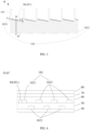
FIG. 1 is a schematic diagram of a basic structure of a fan-out wiring in the prior art. -
FIG. 2 is a schematic diagram of a basic structure of a display panel provided by an embodiment of the present application. -
FIG. 3 is a first enlarged view of B inFIG. 2 . -
FIG. 4 is a cross-sectional view taken along the line D-D' inFIG. 3 . -
FIG. 5a and FIG. 5b are relative positional relationship diagrams of a widened portion and a first line section provided by embodiments of the present application. -
FIG. 6 is a schematic diagram of a basic structure of fan-out wirings provided by an embodiment of the present application. -
FIG. 7 is a second enlarged view of B inFIG. 2 . -
FIG. 8 is a third enlarged view of B inFIG. 2 . -
FIG. 9 is a fourth enlarged view of B inFIG. 2 . - The technical solutions in the embodiments of the present application will be clearly and completely described below with reference to the accompanying drawings in the embodiments of the present application. In the drawings, for clarity and ease of understanding and description, dimensions and thicknesses of components depicted in the drawings are not to scale.
- Refers to
FIG. 1 , which is a schematic diagram of a basic structure of the fan-out wiring in the prior art, and is specifically a structural diagram of the fan-out wiring actually manufactured in the prior art. It is appreciated that after a bezel is compressed, a line width of the fan-out wiring is compressed correspondingly. It can be clearly seen fromFIG. 1 that the fan-out wiring at the corner C is obviously thinner and has a higher risk of disconnection. Embodiments of the present application can solve the above-mentioned defects. - As shown in
FIG. 2 , which is a schematic diagram of a basic structure of a display panel provided by an embodiment of the present application, the display panel includes a display area A1 and a fan-out area A2 defined at one side of the display area A1, the fan-out area A2 includes a plurality of fan-out wirings 10 that are insulated from one another, and each of the fan-out wirings 10 includes: astraight section 101 and aninclined section 102, theinclined section 102 is electrically connected to one end of thestraight section 101 away from the display area, wherein the inclined section is arranged at an obtuse angle with the straight section A1 (an angle c between theinclined section 102 and thestraight section 101 is greater than 90 degrees and less than 180 degrees); wherein the display panel further includes a plurality of protection members (not shown), the plurality of protection members are in one-to-one correspondence with theinclined sections 102 of the plurality of fan-out wirings 10, each of the protection members is close to a corresponding one of theinclined sections 102, an orthographic projection of each of the protection members on a plane where the fan-out wirings 10 are located is located in an area between adjacent ones of thestraight sections 101, and each of the protection members has an included angle of greater than 0 degrees and less than 180 degrees with thestraight sections 101. - It is appreciated that, since the line width of the fan-out wiring is compressed to achieve a narrow bezel in the prior art, the line width of the oblique fan-out wirings actually manufactured at the corner is relatively thin, which is prone to disconnection. In the embodiment of the present application, the plurality of protection members in one-to-one correspondence with the
inclined sections 102 are disposed in the area between adjacent ones of thestraight sections 101, each of the protection members is close to a corresponding one of theinclined sections 102, an orthographic projection of each of the protection members on a plane where the fan-outwirings 10 are located is located in an area between adjacent ones of thestraight sections 101, so as to protect the fan-outwirings 10 at the corner, the stability of the fan-outwiring 10 is enhanced under the premise of compressing the line width, and the risk of disconnection the oblique fan-outwiring 10 at the corner is reduced, so as to realize an ultra-narrow bezel. - In an embodiment, the display panel further includes an integrated
circuit chip 20 located in the fan-out area A2, theintegrated circuit chips 20 are configured to provide driving electrical signals required for the display area A1, and the integratedcircuit chips 20 transmit driving electrical signals to the display area A1 through the fan-out wirings 10. - Next, referring
FIG. 3 , which is a first enlarged view of B inFIG. 2 , specifically, theinclined section 102 includes afirst line section 1021 and asecond line section 1022. A first end of thefirst line section 1021 is electrically connected to one end of thestraight section 101 away from the display area A1 (as shown inFIG. 1 ), and a second end of thefirst line section 1021 is electrically connected to thesecond line section 1022; thefirst line section 1021 is located in an area between one of thestraight sections 101 electrically connected to thefirst line section 1021 and an adjacent one of thestraight sections 101; wherein each of theprotection members 30 includes awidened portion 301, a first end of the widenedportion 301 is electrically connected to one of thestraight sections 101, and a second end of the widenedportion 301 is electrically connected to thesecond line section 1022. - It should be noted that two dotted lines L1 and L2 on the fan-
out wiring 10 inFIG. 3 further explain the division of thestraight section 101 , thefirst line section 1021 and thesecond line segment 1022 The junction between thestraight section 101 and thefirst line section 1021 is represented by the dotted line L1, and the junction between thefirst line section 1021 and thesecond line section 1022 is represented by the dotted line L2. That is, thefirst line section 1021 is located in the area between thestraight section 101 on the dotted line L1 and thestraight section 101 on the dotted line L2. - It is appreciated that, in this embodiment, by disposing the widened
portion 301 between thestraight section 101 and thesecond line section 1022, the widenedportion 301 can widen thefirst line section 1021, and reduce the impact on a load effect of the wiring process due to the thinness of thefirst line section 1021, and the risk of disconnection of thefirst line section 1021 is reduced, so as to achieve the purpose of protecting the fan-outwiring 10. - In an embodiment, the widened
portion 301 is disposed in contact with thefirst line section 1021. It is appreciated that, in this embodiment, the width of thefirst line section 1021 is increased by attaching the widenedportion 301 to thefirst line section 1021, so as to compensate a load of thefirst line section 1021 and reduce a risk of disconnection of thefirst line section 1021. - It should be noted that, when the widened
portion 301 and thefirst line section 1021 are attached, the material of the widenedportion 301 can be a conductive material, or a non-conductive but corrosion-resistant material, which can reduce an influence of etchant on thefirst line section 1021, protect thefirst line section 1021, and improve the stability of the fan-out wirings 10. - In an embodiment, the widened
portion 301 and thefirst line section 1021 are disposed in the same layer, and the widenedportion 301 is located at a side of thefirst line section 1021 close to the display area A1. - It is appreciated that, the widened
portion 301 and thefirst line section 1021 in this embodiment are disposed in the same layer, and can be formed in one exposure process, and thefirst line section 1021 is widened and compensated by using the metal in the same layer, without any additional process flow, so that the manufacturing method is simple and practical. - It should be noted that, with reference to
FIG. 3 , in this embodiment, by arranging the widenedportion 301 at the side of thefirst line section 1021 close to the display area A1, a distance between thefirst line section 1021 and asecond line section 1022 of an adjacent one of the fan-out wirings 10 can be prevented from changing, which may otherwise result in a short circuit between thefirst line section 1021 and thesecond line section 1022 of an adjacent one of the fan-out wirings 10, thus improving the stability of the fan-out wirings 10. - In an embodiment, in a direction perpendicular to an extending direction of the
inclined section 102, a sum of the width of thefirst line section 1021 and the width of thewidened portion 301 is greater than or equal to the width of thesecond line section 1022. - It is appreciated that, before the widened
portion 301 is provided, the width of thefirst line section 1021 is smaller than the width of thesecond line section 1022 in a direction perpendicular to an extending direction of theinclined section 102, which causes thefirst line section 1021 to be prone to disconnection. In this embodiment, the widenedportion 301 is provided, and the sum of the width of thefirst line section 1021 and the width of the widenedportion 301 is greater than or equal to the width of thesecond line section 1022, that is, the widenedportion 301 can increase the width of thefirst line section 1021, so that the risk of disconnection of thefirst line section 1021 can be reduced. - In an embodiment, in a direction perpendicular to an extending direction of the
inclined section 102, a sum of the width of thefirst line section 1021 and the width of the widenedportion 301 is greater than or equal to 1. 8 µm. - It should be noted that, in this embodiment, the widened
portion 301 specifically compensates for the portion where the line width of thefirst line section 1021 is less than 1.8 micrometers, and compensates the line width of thefirst line section 1021 to 1.8 micrometers or more than 1.8 microns. - In one embodiment, refers to
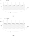
FIG. 4 , which is a cross-sectional view taken along the line DD' inFIG. 3 , that is, a film stacking diagram of the display panel in the fan-out area A2. It should be noted thatFIG. 4 illustrates an example in which theinclined sections 102 are arranged in the same layers as the first gate metal layer and the second gate metal layer respectively. In other embodiments, theinclined sections 102 may be arranged in the same layer only with the first gate metal layer or only with the second gate metal layer. - Specifically, the
inclined sections 102 of the plurality of fan-out wirings 10 in this embodiment are alternately routed in the first gate metal layer and the second gate metal layer, that is, theinclined sections 102 of adjacent ones of the fan-outwirings 10 respectively located in the first gate metal layer and the second gate metal layer. Thefirst line section 1021 of theinclined section 102 close to the display area A1 is thinner than thesecond line section 1022 and is prone to disconnection. In the present application, theprotection member 30 is provided at thefirst line section 1021, and theprotection member 30 including a widenedportion 301 is arranged on the same layer as thefirst line section 1021 to increase the width of thefirst line section 1021 and reduce the risk of disconnection of thefirst line section 1021, so as to achieve the purpose of protecting the fan-outwirings 10. - It should be noted that, as shown in
FIG. 4 , when theinclined sections 102 of adjacent ones of the fan-outwirings 10 are located in the first gate metal layer and the second gate metal layer respectively, that is, when adjacent ones of theinclined sections 102 are arranged in different layers, the widenedportion 301 can also be arranged on the side of thefirst line section 1021 away from the display area A1, that is, arranged above an adjacentinclined section 102, and no short circuit will occur in this case. - In this embodiment, the display panel includes a
substrate layer 40, an insulatinglayer 50, aplanarization layer 60, afirst passivation layer 70, and asecond passivation layer 80; and the first gate metal layer is located on thesubstrate layer 40 and the insulatinglayer 50. The second gate metal layer is located between the insulatinglayer 50 and theplanarization layer 60, thefirst passivation layer 70 is located on a side of theplanarization layer 60 away from the insulatinglayer 50, and thesecond passivation layer 80 is located on a side of thefirst passivation layer 70 away from theplanarization layer 60 is. - In an embodiment, as shown in
FIG. 5a and FIG. 5b , which are relative positional relationship diagrams of a widened portion and a first line section provided by embodiments of the present application, in the direction of the light-exiting side of the display panel, the widenedportion 301 and thefirst line section 1021 are stacked, and both the widenedportion 301 and thefirst line section 1021 are disposed on thesubstrate layer 40. It should be noted that, in this embodiment, by arranging the widenedportion 301 above the first line section 1021 (as shown inFIG. 5a ) or below the first line section 1021 (as shown inFIG. 5b ), thefirst line section 1021 can be widened without impacting an original arrangement of the fan-outwirings 10. - Next, refers to
FIG. 6 , which is a schematic diagram of a basic structure of fan-out wirings provided by an embodiment of the present application, and specifically a structural diagram of the fan-outwirings 10 actually manufactured in the present application. In the present application, a widening compensation is performed at thefirst line section 1021, and after compensation, a line width of the exposed wiring (the first line section 1021) and a line width of thesecond line section 1022 in the inner dense wiring area are equivalent, thereby reducing a risk of disconnection of thefirst line sections 1021 - Next, referring
FIG. 7 , which is a second enlarged view of B inFIG. 2 , specifically, theinclined section 102 includes afirst line section 1021 and asecond line section 1022. A first end of thefirst line section 1021 is electrically connected to one end of thestraight section 101 away from the display area A1 (as shown inFIG. 1 ), and a second end of thefirst line section 1021 is electrically connected to thesecond line section 1022; thefirst line section 1021 is located in an area between one of thestraight sections 101 electrically connected to thefirst line section 1021 and an adjacent one of thestraight sections 101; wherein each of theprotection members 30 includes a widenedportion 301, a first end of the widenedportion 301 is electrically connected to one of thestraight sections 101, and a second end of the widenedportion 301 is electrically connected to thesecond line section 1022. In this embodiment, the widenedportion 301 is disposed separately from thefirst line section 1021, and the widenedportion 301 is located at a side of thefirst line section 1021 close to the display area A1. - It is appreciated that in this embodiment, a first end of the widened
portion 301 is electrically connected to one of thestraight sections 101, a second end of the widenedportion 301 is electrically connected to thesecond line section 1022, but the widenedportion 301 is disposed separately from thesecond line section 1022, that is, the driving electrical signal on thesecond line section 1022 can be transmitted to thestraight section 101 through thefirst line section 1021, and the driving electrical signal on thesecond line section 1022 can also be transmitted to thestraight section 101 through the widenedportion 301. It is equivalent to that the wideningsection 301 and thefirst line section 1021 are arranged in parallel, if thefirst line section 1021 is disconnected, the driving electrical signal can also be transmitted through the wideningsection 301, which will not cause abnormal display of a partial screen of the display panel. - It should be noted that a material of the widened
portion 301 in this embodiment is a conductive material. - Next, referring
FIG. 8 , which is a third enlarged view of B inFIG. 2 . In this embodiment, each of theprotection members 30 includes a blockingportion 302, the blockingportion 302 is disposed separately from the fan-outwirings 10, the blockingportion 302 and theinclined section 102 are disposed in the same layer, and the blockingportion 302 is located at a side of theinclined section 102 close to the display area A1. - It is appreciated that, in this embodiment, by disposing the blocking
portion 302 at the side of theinclined section 102 close to the display area A1, the blockingportion 302 can block the etchant at the peripheral, so as to prevent the etchant from over-etching thefirst line section 1021 and causing disconnection of thefirst line section 1021. It should be noted that the material of the blockingportion 302 may be a corrosion-resistant non-conductive material or a conductive material. - In one embodiment, the blocking
portion 302 includes a plurality of blockingline sections 3021, and the plurality of the blockingline sections 3021 are provided separately. It should be noted that the blockingportion 302 is composed of a plurality of blockingline sections 3021, the plurality of blockingline sections 3021 are arranged in parallel with theinclined sections 102, and a distance between the plurality of blockingline sections 3021 is gradually decreased along a direction away from the display area A1 (as shown inFIG. 1 ). It is appreciated that when a distance between the plurality of blockingline sections 3021 gradually decreases along a direction away from the display area A1, that is, the blockingline sections 3021 close to theinclined section 102 are set more densely, which can improve the blocking effect and prevent the etchant at the periphery from over-etching of thefirst line section 1021 to cause disconnection of thefirst line section 1021. - It should be noted that when the material of the blocking
portion 302 is a non-conductive material, the blockingportion 302 will not cause a short circuit between adjacent ones of the fan-outwirings 10, and distances between the blockingportion 302 and ones of thestraight sections 101 on both the left and right sides of the blockingportion 302 can be further reduced to improve the blocking effect. - In an embodiment, the width of the
blocking line section 3021 is equal to the width of theinclined section 102 in a direction perpendicular to an extending direction of theinclined section 102. It should be noted that, the blockingline section 3021 and theinclined section 102 can be manufactured by using the same photomask to save production cost. - In an embodiment, in the extending direction of the
straight section 101, the distance between the blockingportion 302 and theinclined section 102 is smaller than the distance between adjacent ones of theinclined sections 102. It is appreciated that, in this embodiment, by setting the distance between the blockingportion 302 and theinclined section 102 to be smaller than the distance between adjacent ones of theinclined sections 102, the blocking effect can be improved. - In one embodiment, as shown in
FIG. 9 , which is a fourth enlarged view of B inFIG. 2 , each of theprotection members 30 includes a widenedportion 301 and a blockingportion 302. A first end is electrically connected to one of thestraight sections 101, the second end of the widenedportion 301 is electrically connected to thesecond line section 1022, the blockingportion 302 is separated from the fan-outwiring 10, the blockingportion 302 is disposed on the same layer as theinclined section 102, and the blockingportion 302 is located at the side of theinclined section 102 close to the display area A1. - It is appreciated that, in this embodiment, by dividing the
protection member 30 into a widenedportion 301 and a blockingportion 302, the widenedportion 301 can widen thefirst line section 1021 and reduce the risk of disconnection of thefirst line section 1021, and the blockingportion 302 can block the etchant to prevent the etchant from over-etching thefirst line section 1021, and can also reduce the risk of disconnection of thefirst line section 1021. This embodiment can further improve the stability of the fan-outwirings 10. - In this embodiment, the widened
portion 301 is disposed in contact with thefirst line section 1021. It is appreciated that, in this embodiment, the width of thefirst line section 1021 is increased by attaching the widenedportion 301 to thefirst line section 1021, so as to compensate a load of thefirst line section 1021 and reduce a risk of disconnection of thefirst line section 1021. - It should be noted that, when the widened
portion 301 and thefirst line section 1021 are attached, the material of the widenedportion 301 can be a conductive material, or a non-conductive but corrosion-resistant material, which can reduce an influence of etchant on thefirst line section 1021, protect thefirst line section 1021, and improve the stability of the fan-outwirings 10. - In an embodiment, the widened
portion 301 and thefirst line section 1021 are disposed in the same layer, and the widenedportion 301 is located at a side of thefirst line section 1021 close to the display area A1. - It is appreciated that, the widened
portion 301 and thefirst line section 1021 in this embodiment are disposed in the same layer, and can be formed in one exposure process, and thefirst line section 1021 is widened and compensated by using the metal in the same layer, without any additional process flow, so that the manufacturing method is simple and practical. - It should be noted that, in this embodiment, by arranging the widened
portion 301 at the side of thefirst line section 1021 close to the display area A1, a distance between thefirst line section 1021 and asecond line section 1022 of an adjacent one of the fan-outwirings 10 can be prevented from changing, which may otherwise result in a short circuit between thefirst line section 1021 and thesecond line section 1022 of an adjacent one of the fan-outwirings 10, thus improving the stability of the fan-outwirings 10. - In an embodiment, in a direction perpendicular to an extending direction of the
inclined section 102, a sum of the width of thefirst line section 1021 and the width of the widenedportion 301 is greater than or equal to the width of thesecond line section 1022. - It is appreciated that, before the widened
portion 301 is provided, the width of thefirst line section 1021 is smaller than the width of thesecond line section 1022 in a direction perpendicular to an extending direction of theinclined section 102, which causes thefirst line section 1021 to be prone to disconnection. In this embodiment, the widenedportion 301 is provided, and the sum of the width of thefirst line section 1021 and the width of the widenedportion 301 is greater than or equal to the width of thesecond line section 1022, that is, the widenedportion 301 can increase the width of thefirst line section 1021, so that the risk of disconnection of thefirst line section 1021 can be reduced. - In an embodiment, in a direction perpendicular to an extending direction of the
inclined section 102, a sum of the width of thefirst line section 1021 and the width of the widenedportion 301 is greater than or equal to 1. 8 µm. - It should be noted that, in this embodiment, the widened
portion 301 specifically compensates for the portion where the line width of thefirst line section 1021 is less than 1. 8 micrometers, and compensates the line width of thefirst line section 1021 to 1. 8 micrometers or more than 1. 8 microns. - In an embodiment, in the direction of the light-exiting side of the display panel, the widened
portion 301 and thefirst line section 1021 are stacked. It should be noted that, by arranging the widenedportion 301 above or below thefirst line section 1021 in this embodiment, thefirst line section 1021 can be widened without impacting an original arrangement of the fan-outwirings 10. - In an embodiment, the widened
portion 301 is disposed separately from thefirst line section 1021, and the widenedportion 301 is located at a side of thefirst line section 1021 close to the display area A1. It is appreciated that in this embodiment, a first end of the widenedportion 301 is electrically connected to one of thestraight sections 101, a second end of the widenedportion 301 is electrically connected to thesecond line section 1022, but the widenedportion 301 is disposed separately from thesecond line section 1022, that is, the driving electrical signal on thesecond line section 1022 can be transmitted to thestraight section 101 through thefirst line section 1021, and the driving electrical signal on thesecond line section 1022 can also be transmitted to thestraight section 101 through the widenedportion 301. It is equivalent to that the wideningsection 301 and thefirst line section 1021 are arranged in parallel, if thefirst line section 1021 is disconnected, the driving electrical signal can also be transmitted through the wideningsection 301, which will not cause abnormal display of a partial screen of the display panel. - Embodiments of the present application further provide a display terminal, including a terminal body and the above-mentioned display panel, wherein the terminal body and the display panel are combined into a whole. Specific structure of the display panel can be referred to related descriptions for
FIG. 2 to FIG. 9 , which will not be repeated herein for brevity. The display terminal provided by an embodiment of the present application may be a product or component with a display function, such as a mobile phone, a tablet computer, a notebook computer, a TV, a digital camera, a navigator, and so on. - The display panel and the display terminal provided by the embodiments of the present application are described in detail above. It should be understood that the exemplary embodiments described herein should be regarded as descriptive only, and are used to help understand the method and the core idea of the present application, but not to limit the present application.
Claims (20)
- A display panel, comprising a display area and a fan-out area defined at one side of the display area, the fan-out area comprises a plurality of fan-out wirings being insulated from each other, and each of the fan-out wirings comprises:a straight section; andan inclined section electrically connected to one end of the straight section away from the display area, wherein the inclined section is arranged at an obtuse angle with the straight section;wherein the display panel further comprises a plurality of protection members, the plurality of protection members are in one-to-one correspondence with the inclined sections of the plurality of fan-out wirings, each of the protection members is close to a corresponding one of the inclined sections, an orthographic projection of each of the protection members on a plane where the fan-out wirings are located is located in an area between adjacent ones of the straight sections, and each of the protection members has an included angle of greater than 0 degrees and less than 180 degrees with the straight sections.
- The display panel according to claim 1, wherein each of the inclined sections comprises a first line section and a second line section, and a first end of the first line section is electrically connected to the end of the straight section away from the display area, a second end of the first line section is electrically connected to the second line section, and the first line section is located in an area between one of the straight sections electrically connected to the first line section and an adjacent one of the straight sections; and
wherein each of the protection members comprises a widened portion, a first end of the widened portion is electrically connected to one of the straight sections, and a second end of the widened portion is electrically connected to the second line section. - The display panel according to claim 2, wherein the widened portion is disposed in contact with the first line section.
- The display panel according to claim 3, wherein the widened portion is disposed in a same layer as the first line section, and the widened portion is located at a side of the first line section close to the display area.
- The display panel according to claim 4, wherein, in a direction perpendicular to an extending direction of the inclined section, a sum of a width of the first line section and a width of the widened portion is greater than or equal to a width of the second line section.
- The display panel according to claim 4, wherein, in a direction perpendicular to an extending direction of the inclined sections, a sum of a width of the first line section and a width of the widened portion is greater than or equal to 1. 8 micrometers.
- The display panel according to claim 3, wherein, in a direction of the light-exiting side of the display panel, the widened portion and the first line section are stacked.
- The display panel according to claim 2, wherein the widened portion is spaced apart from the first line section, and the widened portion is located at a side of the first line section close to the display area.
- The display panel according to claim 1, wherein each of the protection members comprises a blocking portion, the blocking portion is spaced apart from the fan-out wirings, the blocking portion is disposed in a same layer as the inclined sections, and the blocking section is located at a side of the inclined sections close to the display area.
- The display panel according to claim 9, wherein the blocking portion comprises a plurality of blocking line sections, and the plurality of blocking line sections are arranged separately.
- The display panel according to claim 10, wherein, in a direction perpendicular to an extending direction of the inclined sections, a width of the blocking line section is equal to a width of each of the inclined sections.
- The display panel according to claim 9, wherein, in an extending direction of the straight sections, a distance between the blocking portion and the inclined section is smaller than a distance between adjacent ones of the inclined sections.
- A display panel, comprising a display area and a fan-out area defined at one side of the display area, the fan-out area comprises a plurality of fan-out wirings being insulated from each other, and each of the fan-out wirings comprises:a straight section; andan inclined section electrically connected to one end of the straight section away from the display area, wherein the inclined section is arranged at an obtuse angle with the straight section;wherein the display panel further comprises a plurality of protection members, the plurality of protection members are in one-to-one correspondence with the inclined sections of the plurality of fan-out wirings, each of the protection members is close to a corresponding one of the inclined sections, an orthographic projection of each of the protection members on a plane where the fan-out wirings are located is located in an area between adjacent ones of the straight sections, and each of the protection members has an included angle of greater than 0 degrees and less than 180 degrees with the straight sections;wherein each of the inclined sections comprises a first line section and a second line section, and a first end of the first line section is electrically connected to the end of the straight section away from the display area, a second end of the first line section is electrically connected to the second line section, and the first line section is located in an area between one of the straight sections electrically connected to the first line section and an adjacent one of the straight sections; andwherein each of the protection members comprises a blocking portion, the blocking portion is spaced apart from the fan-out wirings, the blocking portion is disposed in a same layer as the inclined sections, and the blocking portion is located at a side of the inclined sections close to the display area.
- The display panel according to claim 13, wherein the widened portion is disposed in contact with the first line section.
- The display panel according to claim 14, wherein, in a direction of the light-exiting side of the display panel, the widened portion and the first line section are stacked.
- A display terminal, comprising a terminal main body and a display panel, wherein the terminal main body and the display panel are combined into a whole, the display panel comprises the fan-out area comprises a plurality of fan-out wirings being insulated from each other, and each of the fan-out wirings comprises:a straight section; andan inclined section electrically connected to one end of the straight section away from the display area, wherein the inclined section is arranged at an obtuse angle with the straight section;wherein the display panel further comprises a plurality of protection members, the plurality of protection members are in one-to-one correspondence with the inclined sections of the plurality of fan-out wirings, each of the protection members is close to a corresponding one of the inclined sections, an orthographic projection of each of the protection members on a plane where the fan-out wirings are located is located in an area between adjacent ones of the straight sections, and each of the protection members has an included of greater than 0 degrees and less than 180 degrees with the straight sections.
- The display terminal according to claim 16, wherein each of the inclined sections comprises a first line section and a second line section, and a first end of the first line section is electrically connected to the end of the straight section away from the display area, a second end of the first line section is electrically connected to the second line section, and the first line section is located in an area between one of the straight sections electrically connected to the first line section and an adjacent one of the straight sections; and
wherein each of the protection members comprises a widened portion, a first end of the widened portion is electrically connected to one of the straight sections, and a second end of the widened portion is electrically connected to the second line section. - The display terminal according to claim 17, wherein the widened portion is spaced apart from the first line section, and the widened portion is located at a side of the first line section close to the display area.
- The display terminal according to claim 16, wherein each of the protection members comprises a blocking portion, the blocking portion is spaced apart from the fan-out wiring, the blocking portion is disposed in a same layer as the inclined sections, and the blocking section is located at a side of the inclined sections close to the display area.
- The display terminal according to claim 19, wherein, in an extending direction of the straight sections, a distance between the blocking portion and the inclined section is smaller than a distance between adjacent ones of the inclined sections.
Applications Claiming Priority (2)
| Application Number | Priority Date | Filing Date | Title |
|---|---|---|---|
| CN202210642029.4A CN114883348A (en) | 2022-06-07 | 2022-06-07 | Display panel and display terminal |
| PCT/CN2022/103077 WO2023236294A1 (en) | 2022-06-07 | 2022-06-30 | Display panel and display terminal |
Publications (2)
| Publication Number | Publication Date |
|---|---|
| EP4539123A1 true EP4539123A1 (en) | 2025-04-16 |
| EP4539123A4 EP4539123A4 (en) | 2026-04-15 |
Family
ID=82679725
Family Applications (1)
| Application Number | Title | Priority Date | Filing Date |
|---|---|---|---|
| EP22927585.4A Pending EP4539123A4 (en) | 2022-06-07 | 2022-06-30 | DISPLAY PANEL AND DISPLAY DEVICE |
Country Status (4)
| Country | Link |
|---|---|
| US (1) | US12426460B2 (en) |
| EP (1) | EP4539123A4 (en) |
| CN (1) | CN114883348A (en) |
| WO (1) | WO2023236294A1 (en) |
Family Cites Families (30)
| Publication number | Priority date | Publication date | Assignee | Title |
|---|---|---|---|---|
| US5982470A (en) * | 1996-08-29 | 1999-11-09 | Sharp Kabushiki Kaisha | Liquid crystal display device having dummy electrodes with interleave ratio same on all sides |
| JP3709079B2 (en) * | 1998-08-31 | 2005-10-19 | 京セラ株式会社 | Liquid crystal display device |
| JP4132580B2 (en) * | 1999-08-06 | 2008-08-13 | シャープ株式会社 | Wiring structure, substrate manufacturing method, liquid crystal display device, and manufacturing method thereof |
| JP3531633B2 (en) * | 2000-09-14 | 2004-05-31 | セイコーエプソン株式会社 | Liquid crystal devices and electronic equipment |
| JP2002169487A (en) * | 2000-09-22 | 2002-06-14 | Seiko Epson Corp | Electro-optical devices and electronic equipment |
| US6806938B2 (en) * | 2001-08-30 | 2004-10-19 | Kyocera Corporation | Liquid crystal display device with particular on substrate wiring, portable terminal and display equipment provided with the liquid crystal display device |
| TW525021B (en) * | 2001-11-22 | 2003-03-21 | Chi Mei Optoelectronics Corp | Liquid crystal display device and its thin film transistor substrate |
| JP4005410B2 (en) * | 2002-05-15 | 2007-11-07 | 株式会社 日立ディスプレイズ | Image display device |
| JP4674287B2 (en) * | 2003-12-12 | 2011-04-20 | 奇美電子股▲ふん▼有限公司 | Image display device |
| KR100831306B1 (en) * | 2004-03-17 | 2008-05-22 | 엘지디스플레이 주식회사 | LCD display device |
| JP5260912B2 (en) | 2007-07-31 | 2013-08-14 | パナソニック液晶ディスプレイ株式会社 | Display device |
| KR101433109B1 (en) * | 2007-10-16 | 2014-08-26 | 엘지디스플레이 주식회사 | An Array Substrate of Liquid Crystal Display Device and the method for fabricating thereof |
| JP2009140397A (en) * | 2007-12-10 | 2009-06-25 | Shinko Electric Ind Co Ltd | Automatic wiring design method and computer program therefor |
| CN101673004B (en) * | 2009-10-15 | 2013-04-17 | 友达光电股份有限公司 | Touch-control display panel and display device |
| US20130242511A1 (en) * | 2010-11-16 | 2013-09-19 | Sharp Kabushiki Kaisha | Wiring board, display panel, and electronic apparatus |
| CN103399434B (en) * | 2013-08-01 | 2015-09-16 | 深圳市华星光电技术有限公司 | Display panel and Fanout line structure thereof |
| JP6451258B2 (en) * | 2014-11-25 | 2019-01-16 | 大日本印刷株式会社 | Electrode substrate for touch panel, touch panel, and display device |
| KR102246382B1 (en) * | 2014-12-29 | 2021-04-30 | 엘지디스플레이 주식회사 | Display device and display panel with static electricity preventing pattern |
| KR102378551B1 (en) * | 2015-06-25 | 2022-03-25 | 삼성디스플레이 주식회사 | Display device |
| CN105679744A (en) * | 2016-03-29 | 2016-06-15 | 京东方科技集团股份有限公司 | Fan-out line structure, display panel and manufacturing method thereof |
| KR102777195B1 (en) * | 2016-10-13 | 2025-03-06 | 삼성디스플레이 주식회사 | Organic light emitting display device |
| KR102417112B1 (en) * | 2017-09-28 | 2022-07-06 | 삼성디스플레이 주식회사 | Display apparatus |
| CN108681415A (en) * | 2018-04-28 | 2018-10-19 | 上海中航光电子有限公司 | A kind of array substrate, display panel and display device |
| CN109300921B (en) * | 2018-11-15 | 2020-09-01 | 昆山龙腾光电股份有限公司 | Array substrate and display panel |
| CN109445135A (en) * | 2018-12-12 | 2019-03-08 | 惠科股份有限公司 | Display panel and repairing method thereof |
| CN209150099U (en) * | 2019-01-09 | 2019-07-23 | 昆山工研院新型平板显示技术中心有限公司 | A kind of display panel and display device |
| CN111625120A (en) * | 2020-05-07 | 2020-09-04 | 武汉华星光电技术有限公司 | Display panel |
| CN114141825B (en) * | 2021-11-09 | 2023-04-07 | 武汉华星光电半导体显示技术有限公司 | Display panel and mobile terminal |
| CN117016055A (en) * | 2022-03-01 | 2023-11-07 | 京东方科技集团股份有限公司 | Display substrate and manufacturing method thereof, display device |
| CN115148774B (en) * | 2022-06-30 | 2024-10-29 | 厦门天马显示科技有限公司 | Display panel and display device |
-
2022
- 2022-06-07 CN CN202210642029.4A patent/CN114883348A/en active Pending
- 2022-06-30 US US17/795,550 patent/US12426460B2/en active Active
- 2022-06-30 WO PCT/CN2022/103077 patent/WO2023236294A1/en not_active Ceased
- 2022-06-30 EP EP22927585.4A patent/EP4539123A4/en active Pending
Also Published As
| Publication number | Publication date |
|---|---|
| CN114883348A (en) | 2022-08-09 |
| US20240188356A1 (en) | 2024-06-06 |
| WO2023236294A1 (en) | 2023-12-14 |
| US12426460B2 (en) | 2025-09-23 |
| EP4539123A4 (en) | 2026-04-15 |
Similar Documents
| Publication | Publication Date | Title |
|---|---|---|
| US20260118726A1 (en) | Display panel and display device | |
| US12105383B2 (en) | Array substrate having conductive bumps, liquid crystal display panel and method for manufacturing the same, and display apparatus | |
| US10192893B2 (en) | Array substrate and display device | |
| US12422966B2 (en) | Touch display panel, touch display apparatus and touch display mother board | |
| US12520430B2 (en) | Display module and mobile terminal | |
| US12279485B2 (en) | Display panel and display device | |
| US20230154427A1 (en) | Array substrate and display device | |
| US12608111B2 (en) | Touch structure, display panel and display apparatus | |
| WO2024109061A1 (en) | Display panel and display device | |
| EP4239620B1 (en) | Display base plate and display device | |
| US12287554B2 (en) | Array substrate, preparation method thereof, display panel and display apparatus | |
| US20200144307A1 (en) | Array substrate, manufacturing method of the array substrate, and display device | |
| US20250271962A1 (en) | Touch display panel and display device | |
| US12426460B2 (en) | Display panel and display terminal | |
| US12349569B2 (en) | Display substrate and display device | |
| KR102952814B1 (en) | Display panel and electronic device | |
| CN110738936A (en) | Component substrate and splicing electronic device | |
| US20210325985A1 (en) | Touch structure and method for manufacturing the same, touch substrate, display substrate | |
| US20250160143A1 (en) | Array substrate and display panel | |
| US20240276844A1 (en) | Display substrate and display device | |
| US20240258478A1 (en) | Light-emitting substrate, method for manufacturing the same, and display device | |
| US20240411184A1 (en) | Array substrate, liquid crystal display panel and method for manufacturing the same, and display apparatus | |
| WO2023097599A1 (en) | Display substrate and electronic device | |
| US20260052868A1 (en) | Display substrate and display device | |
| US11294249B2 (en) | Liquid crystal display panel and manufacturing method |
Legal Events
| Date | Code | Title | Description |
|---|---|---|---|
| STAA | Information on the status of an ep patent application or granted ep patent |
Free format text: STATUS: UNKNOWN |
|
| STAA | Information on the status of an ep patent application or granted ep patent |
Free format text: STATUS: THE INTERNATIONAL PUBLICATION HAS BEEN MADE |
|
| PUAI | Public reference made under article 153(3) epc to a published international application that has entered the european phase |
Free format text: ORIGINAL CODE: 0009012 |
|
| STAA | Information on the status of an ep patent application or granted ep patent |
Free format text: STATUS: REQUEST FOR EXAMINATION WAS MADE |
|
| 17P | Request for examination filed |
Effective date: 20230829 |
|
| AK | Designated contracting states |
Kind code of ref document: A1 Designated state(s): AL AT BE BG CH CY CZ DE DK EE ES FI FR GB GR HR HU IE IS IT LI LT LU LV MC MK MT NL NO PL PT RO RS SE SI SK SM TR |
|
| DAV | Request for validation of the european patent (deleted) | ||
| DAX | Request for extension of the european patent (deleted) | ||
| REG | Reference to a national code |
Ref country code: DE Ref legal event code: R079 Free format text: PREVIOUS MAIN CLASS: H01L0027120000 Ipc: G02F0001134500 |
|
| A4 | Supplementary search report drawn up and despatched |
Effective date: 20260312 |
|
| RIC1 | Information provided on ipc code assigned before grant |
Ipc: G02F 1/1345 20060101AFI20260306BHEP Ipc: H10K 59/131 20230101ALI20260306BHEP |