-
The present invention relates to a process cartridge.
-
Japanese Patent Application Publication No. 2014-016484 discloses a conventional process cartridge configured of a drum cartridge having a photosensitive drum, and a toner cartridge that can accommodate toner and that is removably attached to the drum cartridge. In this art, the drum cartridge has a drum handle that is gripped by a user, and the toner cartridge also has a toner handle that is gripped by the user. The toner handle is positioned on both sides of the drum handle in a state where the toner cartridge is attached to the drum cartridge.
-
When moving the conventional process cartridge, only the drum handle is gripped. Consequently, if a capacity of the toner cartridge is enlarged, for example, the drum cartridge may underdo deformation due to the weight of the toner cartridge.
-
Therefore, it would be desirable if both the toner handle and drum handle could be gripped together.
-
In order to attain the above and other object, according to one aspect, the present invention provides a process cartridge including a drum cartridge and a toner cartridge. The drum cartridge includes a photosensitive drum, a drum frame, and a drum handle. The photosensitive drum is rotatable about a drum axis extending in a first direction. The drum frame supports the photosensitive drum. The drum frame has a first drum-frame end portion and a second drum-frame end portion opposite each other in a second direction orthogonal to the first direction. The first drum-frame end portion is positioned closer to the photosensitive drum than the second drum-frame end portion is to the photosensitive drum in the second direction. The drum handle is provided at the second drum-frame end portion of the drum frame. The toner cartridge is attachable to and detachable from the drum cartridge. The toner cartridge includes a toner frame and a toner handle. The toner frame is configured to store toner therein. The toner frame has a first toner-frame end portion and a second toner-frame end portion opposite each other in the second direction. The first toner-frame end portion is positioned closer to the photosensitive drum than the second toner-frame end portion is to the photosensitive drum in the second direction in a state where the toner cartridge is attached to the drum cartridge. The toner handle is provided at the second toner-frame end portion of the toner frame. The drum frame includes: a first protruding part provided at the second drum-frame end portion of the drum frame; and a second protruding part provided at the second drum-frame end portion of the drum frame. The second protruding part is positioned apart from the first protruding part in the first direction. The drum handle is positioned between the first protruding part and the second protruding part in the first direction. The toner handle includes a grip part extending in the first direction and spaced apart from the second toner-frame end portion in the second direction by a prescribed distance. The grip part is positioned between the first protruding part and the second protruding part in the state where the toner cartridge is attached to the drum cartridge.
-
In the process cartridge according to the one aspect, the drum handle is positioned between the first protruding part and the second protruding part, and the grip part is positioned between the first protruding part and the second protruding part in the state where the toner cartridge is attached to the drum cartridge. With this structure, a user can grip both the drum handle and the grip part together.
-
Further, since the drum frame has the first protruding part and the second protruding part, both the drum handle and the grip part can be protected by these first protruding part and second protruding part. Further, by providing the first protruding part and the second protruding part on the drum frame, rigidity of the drum frame can be enhanced, thereby enhancing rigidity of the process cartridge including the drum cartridge.
-
According to a second aspect, in the process cartridge according to the one aspect, the drum frame may have a groove positioned between the first protruding part and the second protruding part, the groove being configured to receive a part of the toner handle in the state where the toner cartridge is attached to the drum cartridge.
-
With this structure, since the drum frame has at least one groove for receiving a part of the toner handle in the state where the toner cartridge is attached to the drum cartridge, the toner handle can be brought closer to the drum handle, which further facilitate user's grabbing the drum handle and the grip part together.
-
According to a third aspect, in the process cartridge according to the one aspect, the toner handle may further include a first connecting part and a second connecting part; and the drum frame may include a first groove and a second groove. The first connecting part connects one end of the grip part in the first direction to the toner frame. The first connecting part has a first rib protruding farther toward the drum frame than the grip part does. The second connecting part connects an other end of the grip part in the first direction to the toner frame. The second connecting part has a second rib protruding farther toward the drum frame than the grip part does. The first groove is positioned between the first connecting part and the drum handle. The second groove is positioned between the second connecting part and the drum handle. The first rib is received in the first groove and the second rib is received in the second groove in the state where the toner cartridge is attached to the drum cartridge.
-
With this structure, since the drum frame has the first and second grooves in which the first and second ribs can be inserted in the state where the toner cartridge is attached to the drum cartridge, the toner handle can be brought closer to the drum handle. Further, since the first and second ribs protruding farther toward the drum frame than the grip part does, rigidity of the toner handle can also be enhanced.
-
According to a fourth aspect, in the process cartridge according to the third aspect, the toner cartridge may further include a developing roller rotatable about a developing-roller axis extending in the first direction and positioned at the first toner-frame end portion.
-
With this structure, since the developing roller is positioned at the first toner-frame end portion which is closer to the photosensitive drum, the toner cartridge can have a center of gravity at the first toner-frame end portion which is opposite the second toner-frame end portion where the toner handle is provided. Even in this case, the rigidity of the toner handle can also be enhanced by the provision of the first and second connecting parts, enabling the user to stably hold the toner cartridge.
-
According to a fifth aspect, in the process cartridge according to the one aspect, the drum handle may have a plate shape extending in the second direction toward the photosensitive drum from the second drum-frame end portion of the drum frame.
-
According to a sixth aspect, in the process cartridge according to any one of the one through fifth aspects, the drum handle may have one end and an other end in the second direction, the one end of the drum handle being positioned closer to the photosensitive drum than the other end of the drum handle is to the photosensitive drum in the second direction. The one end of the drum handle is positioned closer to the photosensitive drum than the grip part of the toner handle is to the photosensitive drum in the second direction in the state where the toner cartridge is attached to the drum cartridge.
-
With this structure, since the one end of the drum handle is positioned closer to the photosensitive drum than the grip part is to the photosensitive drum in the second direction, the user can reliably grip both the drum handle and the toner handle together.
-
According to a seventh aspect, in the process cartridge according to the one aspect, the drum cartridge may further include a lock lever movable between a locking position and an unlocking position relative to the drum frame. The lock lever is in the locking position in the state where the toner cartridge is attached to the drum cartridge. The lock lever moves the toner cartridge relative to the drum cartridge such that the grip part is separated from the drum handle while the lock lever moves from the locking position to the unlocking position.
-
With this structure, since the lock lever is in the locking position to lock the toner cartridge relative to the drum cartridge in the state where the toner cartridge is attached to the drum cartridge, the user can hold both the drum handle and the toner handle together as long as the lock member is in the locking position. Further, as the lock lever is moved from the locking position to the unlocking position, the grip part can be separated from the drum handle. Hence, the user can grip only the toner handle when the lock lever is placed into the unlocking position from the locking position.
-
According to an eighth aspect, in the process cartridge according to the one aspect, the toner handle and the drum handle may define a gap therebetween in a third direction orthogonal to both the first direction and the second direction in the state where the toner cartridge is attached to the drum cartridge.
-
According to a ninth aspect, in the process cartridge according to the one aspect, each of the first protruding part and the second protruding part may include: a body portion having a box shape that is open toward the photosensitive drum in the second direction; and a plurality of ribs provided at an interior of the body portion and juxtaposed in the first direction.
- Fig. 1 illustrates an image-forming apparatus in which a process cartridge according to one embodiment can be used.
- Fig. 2 illustrates the image-forming apparatus from which the process cartridge is removed.
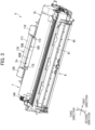
- Fig. 3 is a perspective view of the process cartridge.
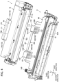
- Fig. 4 is a perspective view of a drum cartridge and a developing cartridge constituting the process cartridge.
- Fig. 5A is a cross-sectional view of the process cartridge.
- Fig. 5B is an enlarged cross-sectional view illustrating a toner handle and a drum handle.
- Fig. 6 is a perspective view of the drum cartridge and the developing cartridge as viewed from a side thereof where the respective handles are positioned.
- Fig. 7 is a perspective view of the developing cartridge as viewed from a side thereof where ribs of the toner handle are positioned.
- Fig. 8A is a perspective view of the process cartridge as viewed from a side thereof where the toner and drum handles are positioned.
- Fig. 8B is a rear view of the process cartridge as viewed from its side where the toner and drum handles are positioned.
- Fig. 9 is a perspective view illustrating a lock lever of the drum cartridge.
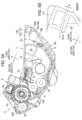
- Fig. 10 is a cross-sectional view illustrating movement of the lock lever of the drum cartridge.
- Fig. 11A is a cross-sectional view illustrating a state where the developing cartridge is attached to the drum cartridge.
- Fig. 11B is a cross-sectional view illustrating a state where the developing cartridge is lifted up from the drum cartridge.
-
Hereinafter, one embodiment of the present invention will be described.
-
As illustrated in Fig. 1, an image-forming device 1 includes a housing 2, a sheet-feeding unit 3, an exposure device 4, a process cartridge 5, and a fixing device 8.
-
The sheet-feeding unit 3 is positioned in a bottom end portion of the housing 2. The sheet-feeding unit 3 includes a sheet tray 31, a pressing plate 32, and a sheet-feeding mechanism 33. The sheet tray 31 functions to accommodate sheets S therein, such as sheets of paper, for example. The pressing plate 32 is configured to press the sheets S in the sheet tray 31 upward. The sheet-feeding mechanism 33 is configured to feed the sheets S lifted by the pressing plate 32 toward the process cartridge 5.
-
The exposure device 4 is positioned above the sheet tray 31. The exposure device 4 includes a light source, a deflector, lenses, mirrors, and the like. The exposure device 4 is configured to emit a laser beam for exposing a peripheral surface of a photosensitive drum 61, as depicted with a phantom line in Fig. 1.
-
The process cartridge 5 is positioned above the sheet-feeding mechanism 33. The process cartridge 5 includes a drum cartridge 6, and a developing cartridge 7 as an example of a toner cartridge of the invention.
-
The drum cartridge 6 includes the photosensitive drum 61, a charger 62, a transfer roller 63, and a drum frame 65. The photosensitive drum 61 is rotatable about a drum axis 61X extending in a first direction. In the present embodiment, the first direction corresponds to a left-right direction of the image-forming device 1.
-
The charger 62 is configured to charge the peripheral surface of the photosensitive drum 61. The transfer roller 63 is rotatable about a transfer roller axis 63X extending in the first direction. The drum frame 65 holds the photosensitive drum 61, the charger 62, and the transfer roller 63.
-
The developing cartridge 7 includes a developing roller 71, a supply roller 72, a thickness-regulating blade 73, an agitator 74, and a toner frame 75.
-
The developing roller 71 is rotatable about a developing roller axis 71X extending in the first direction. The supply roller 72 is rotatable about a supply roller axis 72X extending in the first direction. The thickness-regulating blade 73 is configured to regulate a layer of toner on the developing roller 71 at a uniform thickness.
-
The toner frame 75 holds the developing roller 71, the supply roller 72, the thickness-regulating blade 73, and the agitator 74. The toner frame 75 can accommodate toner therein. Specifically, the toner frame 75 has a toner-accommodating section 76 that can accommodate toner therein.
-
The agitator 74 is rotatable about an agitator axis 74X extending in the first direction. By rotating, the agitator 74 is configured to agitate the toner in the toner-accommodating section 76. The supply roller 72 is configured to supply the toner accommodated in the toner-accommodating section 76 to the developing roller 71.
-
The fixing device 8 is positioned above the process cartridge 5. The fixing device 8 includes a heating roller 81, and a pressure roller 82. The heating roller 81 is configured to heat each sheet S. The pressure roller 82 is configured to nip each sheet S in cooperation with the heating roller 81.
-
In the image-forming device 1, the peripheral surface of the photosensitive drum 61 is charged by the charger 62. In the image-forming device 1, the charged peripheral surface of the photosensitive drum 61 is subsequently exposed to the laser beam irradiated from the exposure device 4. As a result, an electrostatic latent image is formed on the photosensitive drum 61 based on image data. Next, in the image-forming device 1, the toner is supplied from the developing roller 71 onto the electrostatic latent image on the photosensitive drum 61, thereby forming a toner image on the photosensitive drum 61.
-
Subsequently, in the image-forming device 1, a sheet S supplied from the sheet-feeding unit 3 is conveyed to a position between the photosensitive drum 61 and the transfer roller 63, whereby the toner image formed on the photosensitive drum 61 is transferred onto the sheet S. Thereafter, in the image-forming device 1, the sheet S on which the toner image has been transferred is conveyed to a position between the heating roller 81 and pressure roller 82, whereby the toner image transferred on the sheet S is fixed to the sheet S.
-
In the image-forming device 1, the sheet S on which the toner image has been fixed is then discharged onto a discharge tray 2A by a discharge roller 9.
-
The housing 2 includes a housing body 21, and a cover 22. The housing body 21 has an opening 21A. The cover 22 is configured to open and close the opening 21A. The cover 22 is movable, relative to the housing body 21, between a closed position illustrated in Fig. 1 and an open position illustrated in Fig. 2. Specifically, the cover 22 is pivotably movable, relative to the housing body 21, between the closed position and the open position. At the closed position, the cover 22 closes the opening 21A. At the open position, the cover 22 opens the opening 21A.
-
As illustrated in Fig. 2, the process cartridge 5 is attachable and detachable relative to the housing 2. Specifically, the process cartridge 5 can be attached to and detached from the housing body 21 through the opening 21A while the cover 22 is at the open position.
-
As illustrated in Figs. 3 and 4, the developing cartridge 7 is attachable to and detachable from the drum cartridge 6. Fig. 3 illustrates the process cartridge 5 in which the developing cartridge 7 is attached to the drum cartridge 6. Fig. 4 illustrates a state where the developing cartridge 7 is detached from the drum cartridge 6.
-
In the drawings to be referred to hereinafter, arrows are used to indicate the first direction, a second direction, and a third direction. In these drawings, each arrow points to one side in the corresponding direction. Specifically, a leading side of each arrow represents one side in the corresponding direction, and a trailing side of each arrow represents the other side in the corresponding direction. Further, each of the second direction and third direction is orthogonal to the first direction. The third direction crosses the second direction. In the present embodiment, the third direction is orthogonal to both the first direction and the second direction.
-
The drum cartridge 6 further includes a drum handle 160. The developing cartridge 7 further includes a toner handle 170. A user grips the drum handle 160 and the toner handle 170 together when moving the process cartridge 5, and when attaching and detaching the process cartridge 5 to and from the housing 2.
-
As illustrated in Fig. 5A, the toner frame 75 has a first toner end portion 75A, and a second toner end portion 75B. The first toner end portion 75A is an end portion of the toner frame 75 that is positioned closer to the photosensitive drum 61 than the second toner end portion 75B is to the photosensitive drum 61 in the second direction in a state where the developing cartridge 7 is attached to the drum cartridge 6. In other words, the first toner end portion 75A is an end portion of the toner frame 75 at the one side in the second direction.
-
The second toner end portion 75B is an end portion of the toner frame 75 that is positioned farther from the photosensitive drum 61 in the second direction than the first toner end portion 75A is from the photosensitive drum 61. In other words, the second toner end portion 75B is an end portion of the toner frame 75 at the other side in the second direction.
-
The developing roller 71 is positioned at the first toner end portion 75A of the toner frame 75. The toner handle 170 is positioned at the second toner end portion 75B of the toner frame 75.
-
As illustrated in Fig. 4, the toner handle 170 has a toner grip part 171 as an example of a grip part of the invention, and a pair of toner connecting parts 172.
-
The toner grip part 171 is configured to be gripped by a user. The toner grip part 171 extends in the first direction. The toner grip part 171 is spaced apart from the toner frame 75 in the second direction by a prescribed distance. In other words, a through-hole 7H is formed between the toner frame 75 and the toner grip part 171 so that the user can insert his fingers in the through-hole 7H. The developing cartridge 7 has the through-hole 7H. The through-hole 7H extends in the third direction to penetrate the developing cartridge 7 therethrough.
-
The toner connecting parts 172 connect the toner grip part 171 to the toner frame 75. In the present embodiment, the toner connecting parts 172 include a first connecting part 173, and a second connecting part 174.
-
The first connecting part 173 connects one end of the toner grip part 171 in the first direction to the toner frame 75. The first connecting part 173 extends in the second direction. The first connecting part 173 has a plate shape. One end of the first connecting part 173 in the second direction is connected to the second toner end portion 75B of the toner frame 75, while the other end of the first connecting part 173 in the second direction is connected to the toner grip part 171.
-
The second connecting part 174 connects the other end of the toner grip part 171 in the first direction to the toner frame 75. The second connecting part 174 extends in the second direction. The second connecting part 174 has a plate shape. One end of the second connecting part 174 in the second direction is connected to the second toner end portion 75B of the toner frame 75, while the other end of the second connecting part 174 in the second direction is connected to the toner grip part 171. The first connecting part 173 and the second connecting part 174 are symmetrical in structure with respect to the first direction.
-
As illustrated in Figs. 6 and 7, the first connecting part 173 has a first rib 173A. The first rib 173A is a portion of the first connecting part 173 that protrudes farther toward the drum frame 65 than the toner grip part 171 does. Specifically, the first rib 173A is the portion of the first connecting part 173 that protrudes further toward the other side in the third direction relative to the toner grip part 171. The first rib 173A extends in the second direction.
-
The second connecting part 174 has a second rib 174A. The second rib 174A is a portion of the second connecting part 174 that protrudes farther toward the drum frame 65 than the toner grip part 171 does. Specifically, the second rib 174A is the portion of the second connecting part 174 that protrudes further toward the other side in the third direction relative to the toner grip part 171. The second rib 174A extends in the second direction.
-
As illustrated in Fig. 4, the drum frame 65 has a first protruding part 110, and a second protruding part 120.
-
The drum frame 65 has a first drum end portion 65A, and a second drum end portion 65B. The first drum end portion 65A is an end portion of the drum frame 65 that is positioned closer to the photosensitive drum 61 than the second drum end portion 65B is to the photosensitive drum 61 in the second direction. In other words, the first drum end portion 65A is an end portion of the drum frame 65 at the one side in the second direction.
-
The second drum end portion 65B is an end portion of the drum frame 65 that is positioned farther from the photosensitive drum 61 in the second direction than the first drum end portion 65A is from the photosensitive drum 61. In other words, the second drum end portion 65B is an end portion of the drum frame 65 at the other side in the second direction.
-
The first protruding part 110 and the second protruding part 120 are positioned at the second drum end portion 65B of the drum frame 65.
-
The first protruding part 110 protrudes toward the one side in the third direction from the second drum end portion 65B. The first protruding part 110 includes a first body portion 111, and a plurality of first reinforcing ribs 112. The first body portion 111 has a box shape that is open toward the one side in the second direction. The first reinforcing ribs 112 are positioned at an interior of the first body portion 111. The first reinforcing ribs 112 are juxtaposed in the first direction.
-
The second protruding part 120 is spaced apart from the first protruding part 110 in the first direction. Specifically, the first protruding part 110 is positioned on the one side in the first direction relative to a center of the drum cartridge 6 in the first direction. The second protruding part 120 is positioned on the other side in the first direction relative to the center of the drum cartridge 6 in the first direction. The first protruding part 110 and the second protruding part 120 oppose each other in the first direction.
-
The second protruding part 120 protrudes toward the one side in the third direction from the second drum end portion 65B. The second protruding part 120 includes a second body portion 121, and a plurality of second reinforcing ribs 122. The second body portion 121 has a box shape that is open toward the one side in the second direction. The second reinforcing ribs 122 are positioned at an interior of the second body portion 121. The second reinforcing ribs 122 are juxtaposed in the first direction. The first protruding part 110 and the second protruding part 120 are symmetrical in structure with respect to the first direction.
-
The drum handle 160 is positioned at the second drum end portion 65B of the drum frame 65. The drum handle 160 is positioned between the first protruding part 110 and the second protruding part 120 in the first direction. The drum handle 160 has a plate shape. Specifically, the drum handle 160 has a plate-shaped drum grip part 161, and a drum connecting part 162.
-
The drum grip part 161 is configured to be gripped by the user. The drum grip part 161 extends in the second direction. Specifically, the drum grip part 161 extends in the second direction toward the photosensitive drum 61 from the second drum end portion 65B of the drum frame 65 (see also Fig. 5). In other words, the drum grip part 161 extends toward the one side in the second direction from the second drum end portion 65B.
-
The drum connecting part 162 connects respective ends of the drum grip part 161 in the first direction to the drum frame 65. Specifically, the drum connecting part 162 is configured of a third connecting part 163, and a fourth connecting part 164. The third connecting part 163 connects the one end of the drum grip part 161 in the first direction to the second drum end portion 65B of the drum frame 65. The fourth connecting part 164 connects the other end of the drum grip part 161 in the first direction to the second drum end portion 65B of the drum frame 65.
-
Providing the drum connecting part 162 can improve rigidity of the drum grip part 161 (the drum handle 160).
-
In the present embodiment, the drum frame 65 also has a pair of grooves 130. Each groove 130 is configured to receive a part of the toner handle 170 when the developing cartridge 7 is attached to the drum cartridge 6. The grooves 130 are positioned between the first protruding part 110 and the second protruding part 120.
-
In the present embodiment, the drum frame 65 has a first groove 131 and a second groove 132 as the pair of grooves 130.
-
The first groove 131 is positioned between the first protruding part 110 and the drum handle 160. Specifically, the first groove 131 is positioned between the first protruding part 110 and the third connecting part 163 of the drum handle 160. The first groove 131 extends in the second direction.
-
The second groove 132 is positioned between the second protruding part 120 and the drum handle 160. Specifically, the second groove 132 is positioned between the second protruding part 120 and the fourth connecting part 164 of the drum handle 160. The second groove 132 extends in the second direction.
-
As illustrated in Figs. 8A and 8B, in the state where the developing cartridge 7 is attached to the drum cartridge 6, the first rib 173A (which is a part of the toner handle 170) is received in the first groove 131 and the second connecting part 174 (which is a part of the toner handle 170) is received in the second groove 132.
-
In the state where the developing cartridge 7 is attached to the drum cartridge 6, the toner grip part 171 is positioned between the first protruding part 110 and the second protruding part 120 of the drum frame 65 (also see Fig. 3).
-
As illustrated in Figs. 5A and 5B, the toner grip part 171 overlaps the drum handle 160 in the third direction in the state where the developing cartridge 7 is attached to the drum cartridge 6. Specifically, the toner grip part 171 overlaps the drum grip part 161 in the third direction in the state where the developing cartridge 7 is attached to the drum cartridge 6. The toner grip part 171 is positioned adjacent to the drum grip part 161 and on the one side of the drum grip part 161 in the third direction in the state where the developing cartridge 7 is attached to the drum cartridge 6.
-
In the state where the developing cartridge 7 is attached to the drum cartridge 6, a first end 161A of the drum grip part 161 is positioned closer to the photosensitive drum 61 than the toner grip part 171 is to the photosensitive drum 61 in the second direction. In other words, the first end 161A of the drum grip part 161 protrudes farther toward the photosensitive drum 61 in the second direction than the toner grip part 171 does in the state where the developing cartridge 7 is attached to the drum cartridge 6.
-
To put this yet another way, the first end 161A of the drum grip part 161 protrudes further toward the one side in the second direction relative to the toner grip part 171 in the state where the developing cartridge 7 is attached to the drum cartridge 6. The first end 161A of the drum grip part 161 is an end of the drum handle 160 at the one side in the second direction that is closer to the photosensitive drum 61 than the other end of the drum handle 160 in the second direction is to the photosensitive drum 61.
-
In a state where the drum handle 160 and the toner handle 170 are not gripped by the user, a gap G is formed between the drum grip part 161 and the toner grip part 171. The gap G is 1-3 mm, as an example. Incidentally, the drum grip part 161 and the toner grip part 171 may be configured to contact each other or not to contact each other while the user grips the drum handle 160 and the toner handle 170.
-
As illustrated in Fig. 9, the drum cartridge 6 further includes a lock lever 140.
-
The lock lever 140 is configured to lock the developing cartridge 7 relative to the drum cartridge 6 in the state where the developing cartridge 7 is attached to the drum cartridge 6. The lock lever 140 is positioned at an end portion of the drum frame 65 at the other side in the first direction. The lock lever 140 is positioned closer to the second drum end portion 65B than the photosensitive drum 61 is to the second drum end portion 65B in the second direction.
-
As illustrated in Fig. 10, the lock lever 140 is movable, relative to the drum frame 65, between a locking position depicted with solid lines, and an unlocking position depicted with phantom lines. Specifically, the lock lever 140 is pivotable movable, relative to the drum frame 65, between the locking position and the unlocking position.
-
The lock lever 140 includes a shaft portion 141, a lock portion 142, a pressing portion 143, and an operation portion 144.
-
The shaft portion 141 defines a lever axis 140X about which the lock lever 140 is pivotably movable. The lever axis 140X extends in the first direction. The drum frame 65 has a side wall 65D positioned at the other side in the first direction. The shaft portion 141 is rotatably supported by the side wall 65D.
-
While the lock lever 140 is in the locking position, the lock portion 142 functions to lock the developing cartridge 7 to the drum frame 65. The lock portion 142 extends toward the one side in the third direction from the shaft portion 141 while the lock lever 140 is in the locking position. The lock portion 142 has a recess 142A into which a protrusion 77 of the developing cartridge 7 (see Fig. 11A) is inserted.
-
The operation portion 144 is configured to be operated when the user attempts to move the lock lever 140 from the locking position to the unlocking position. While the lock lever 140 is in the locking position, the operation portion 144 extends toward the other side in the second direction from the lock portion 142.
-
The pressing portion 143 is configured to contact the developing cartridge 7 and push the developing cartridge 7 upward when the lock lever 140 is moved from the locking position to the unlocking position. When the lock lever 140 is in the locking position, the pressing portion 143 extends toward the one side in the second direction from the shaft portion 141.
-
As illustrated in Fig. 11A, the lock lever 140 is in the locking position in the state where the developing cartridge 7 is attached to the drum cartridge 6. At this time, the protrusion 77 of the developing cartridge 7 is inside the recess 142A of the lock portion 142, thereby locking the developing cartridge 7 relative to the drum cartridge 6.
-
While the lock lever 140 is being moved from the locking position to the unlocking position illustrated in Fig. 11B, the developing cartridge 7 is moved relative to the drum frame 65 such that the toner grip part 171 is separated from the drum handle 160. Specifically, in association with movement of the lock lever 140 from the locking position to the unlocking position, the recess 142A of the lock portion 142 is disengaged from the protrusion 77 of the developing cartridge 7 and the pressing portion 143 pushes the developing cartridge 7 toward the one side in the third direction.
-
In this way, locking of the developing cartridge 7 to the drum cartridge 6 is released, and the end portion of the developing cartridge 7 at the other side in the second direction is primarily separated from the drum frame 65. As a result, the toner grip part 171 is separated from the drum grip part 161 of the drum handle 160.
-
Now, operational and technical advantages that can be achieved by the embodiment will be described.
-
The drum handle 160 is positioned between the first protruding part 110 and the second protruding part 120, and the toner grip part 171 of the toner handle 170 is positioned between the first protruding part 110 and the second protruding part 120 in the state where the developing cartridge 7 is attached to the drum cartridge 6. With this structure, the user can grip both the toner handle 170 and the drum handle 160 together by inserting his fingers into the space between the toner frame 75 and toner grip part 171 (i.e., the through-hole 7H) in the state where the developing cartridge 7 is attached to the drum cartridge 6.
-
Further, the first protruding part 110 and the second protruding part 120 provided on the drum frame 65 can protect the drum handle 160 and the toner handle 170. Moreover, the first protruding part 110 and second protruding part 120 provided on the drum frame 65 can improve the rigidity of the drum frame 65, which can lead to enhanced rigidity of the drum cartridge 6 and the process cartridge 5 that includes the drum cartridge 6 to which the developing cartridge 7 is attached.
-
The drum frame 65 has the groove 130 in which parts of the toner handle 170 is received in the state where the developing cartridge 7 is attached to the drum cartridge 6. This structure enables the toner grip part 171 to be arranged close to the drum grip part 161 of the drum handle 160 in the state where the developing cartridge 7 is attached to the drum cartridge 6.
-
Specifically, the drum frame 65 has the first groove 131 in which the first rib 173A is received, and the second groove 132 in which the second rib 174A is received while the developing cartridge 7 is attached to the drum cartridge 6. With this structure, the toner grip part 171 can be placed near the drum grip part 161 in the state where the developing cartridge 7 is attached to the drum cartridge 6, thereby facilitating user's gripping of the toner handle 170 and the drum handle 160 together.
-
Further, the first connecting part 173 and the second connecting part 174 protrude farther toward the drum frame 65 than the toner grip part 171 does. This structure can improve the rigidity of the toner handle 170. In other words, dimensions in the third direction of the first connecting part 173 and second connecting part 174 are each larger than a dimension in the third direction of the toner grip part 171. With this structure, the rigidity of the toner handle 170 can be enhanced.
-
Since the developing roller 71 is positioned at the first toner end portion 75A of the toner frame 75, a center of gravity of the developing cartridge 7 can be positioned near the first toner end portion 75A which is opposite the second toner end portion 75B where the toner handle 170 is located. Even in this case, since the rigidity of the toner handle 170 can be enhanced by the first connecting part 173 and the second connecting part 174, the user can stably grab the developing cartridge 7.
-
In the second direction, the first end 161A of the drum handle 160 is positioned closer to the photosensitive drum 61 than the toner grip part 171 is to the photosensitive drum 61. With this structure, the user can reliably grip the drum handle 160 together with the toner grip part 171, and is restricted from grabbing the toner handle 170 alone.
-
Since the lock lever 140 is in the locking position while the developing cartridge 7 is attached to the drum cartridge 6, the user can grab the toner handle 170 and the drum handle 160 together as long as the lock lever 140 is in the locking position. When the lock lever 140 is moved from the locking position to the unlocking position, the toner grip part 171 separates from the drum handle 160. Hence, the user can grab the toner handle 170 alone in a case where the lock lever 140 is moved to the unlocking position from the locking position.
-
While the invention has been described in conjunction with various example structures outlined above and illustrated in the figures, various alternatives, modifications, variations, improvements, and/or substantial equivalents, whether known or that may be presently unforeseen, may become apparent to those having at least ordinary skill in the art. Accordingly, the example embodiments of the disclosure, as set forth above, are intended to be illustrative of the invention, and not limiting the invention. Various changes may be made without departing from the scope of the disclosure. Therefore, the disclosure is intended to embrace all known or later developed alternatives, modifications, variations, improvements, and/or substantial equivalents. Some specific examples of potential alternatives, modifications, or variations in the described invention are provided below:
-
In the embodiment described above, the process cartridge 5 provides the gap G between the drum grip part 161 and the toner grip part 171 while the drum handle 160 and the toner handle 170 are not being gripped. Alternatively, the drum handle and the toner handle of the invention may be designed to contact each other while the drum handle and the toner handle are not being gripped. Specifically, the process cartridge of the invention may be configured such that the drum grip part and the toner grip part contact each other while the drum handle and the toner handle are not being gripped.
-
In the embodiment described above, the drum grip part 161 of the drum handle 160 protrudes further toward the one side in the second direction relative to the toner grip part 171 of the toner handle 170. Alternatively, an endface of the drum grip part at the one side in the second direction may be flush with an endface of the toner grip part at the one side in the second direction. Still alternatively, the toner grip part may protrude further toward the one side in the second direction than the drum grip part.
-
The drum handle of the invention may extend in the first direction so as to be connected to each of the first protruding part and the second protruding part. Further, the drum handle of the invention may have a U-shape similar to the toner handle 170 of the above-described embodiment.
-
In the embodiment described above, the toner handle 170 is configured such that the dimensions of the first and second connecting parts 173 and 174 in the third direction are greater than the dimension of the toner grip part 171 (the grip part) in the third direction.
Alternatively, the toner handle of the invention may be configured such that a dimension of each of the first and second connecting parts in the third direction is equal to a dimension of the grip part in the third direction.
-
In the embodiment described above, the toner handle 170 includes two connecting parts, namely, the first connecting part 173 and the second connecting part 174. Alternatively, the toner handle of the invention may have only one connecting part. In this case, the only one connecting part may be designed to connect either one end of the grip part in the first direction to the toner frame, for example. Still alternatively, the only one connecting part may be designed to connect a center portion of the grip part in the first direction to the toner frame, for example. The drum handle of the invention may be similarly configured.
-
In the embodiment described above, the drum frame 65 has two grooves, namely, the first groove 131 and the second groove 132. However, the drum frame may have three or more grooves for receiving parts of the toner handle, for example. Alternatively, the drum frame may have only one groove for receiving a part of the toner handle. Still alternatively, the drum frame may have no grooves.
-
In the embodiment described above, the toner grip part 171 (the grip part of the invention) is configured to overlap the drum handle 160 in the third direction in the state where the developing cartridge 7 is attached to the drum cartridge 6. However, the grip part of the invention may be configured to overlap the drum handle in the second direction in the state where the developing cartridge is attached to the drum cartridge, for example. Furthermore, the grip part can be configured to overlap the drum handle in any direction orthogonal to the first direction while the developing cartridge is attached to the drum cartridge.
-
In the embodiment described above, the developing cartridge 7 including the developing roller 71 is employed as an example of the toner cartridge of the invention. However, the toner cartridge of the invention may be a toner cartridge without a developing roller. In this case, a toner cartridge without a developing roller may be detachably attachable to a developing cartridge including a developing roller, and may be detachably attachable to a drum cartridge via the developing cartridge. In other words, the process cartridge of the invention may be configured of a toner cartridge, a developing cartridge, and a drum cartridge.
-
In the embodiment described above, the drum frame 65 has the first protruding part 110 and the second protruding part 120. However, the drum frame of the invention may have neither a first protruding part nor a second protruding part.
-
The elements described in the above embodiment and modifications thereof may be implemented in any combination.