EP4538612A1 - Combustion appliance unit for a hybrid system - Google Patents
Combustion appliance unit for a hybrid system Download PDFInfo
- Publication number
- EP4538612A1 EP4538612A1 EP23203419.9A EP23203419A EP4538612A1 EP 4538612 A1 EP4538612 A1 EP 4538612A1 EP 23203419 A EP23203419 A EP 23203419A EP 4538612 A1 EP4538612 A1 EP 4538612A1
- Authority
- EP
- European Patent Office
- Prior art keywords
- combustion appliance
- fluid
- load
- unit
- heat pump
- Prior art date
- Legal status (The legal status is an assumption and is not a legal conclusion. Google has not performed a legal analysis and makes no representation as to the accuracy of the status listed.)
- Withdrawn
Links
Images

Classifications
-
- F—MECHANICAL ENGINEERING; LIGHTING; HEATING; WEAPONS; BLASTING
- F24—HEATING; RANGES; VENTILATING
- F24H—FLUID HEATERS, e.g. WATER OR AIR HEATERS, HAVING HEAT-GENERATING MEANS, e.g. HEAT PUMPS, IN GENERAL
- F24H4/00—Fluid heaters characterised by the use of heat pumps
- F24H4/02—Water heaters
-
- F—MECHANICAL ENGINEERING; LIGHTING; HEATING; WEAPONS; BLASTING
- F24—HEATING; RANGES; VENTILATING
- F24D—DOMESTIC- OR SPACE-HEATING SYSTEMS, e.g. CENTRAL HEATING SYSTEMS; DOMESTIC HOT-WATER SUPPLY SYSTEMS; ELEMENTS OR COMPONENTS THEREFOR
- F24D3/00—Hot-water central heating systems
- F24D3/10—Feed-line arrangements, e.g. providing for heat-accumulator tanks, expansion tanks ; Hydraulic components of a central heating system
- F24D3/1091—Mixing cylinders
-
- F—MECHANICAL ENGINEERING; LIGHTING; HEATING; WEAPONS; BLASTING
- F24—HEATING; RANGES; VENTILATING
- F24H—FLUID HEATERS, e.g. WATER OR AIR HEATERS, HAVING HEAT-GENERATING MEANS, e.g. HEAT PUMPS, IN GENERAL
- F24H1/00—Water heaters, e.g. boilers, continuous-flow heaters or water-storage heaters
- F24H1/10—Continuous-flow heaters, i.e. heaters in which heat is generated only while the water is flowing, e.g. with direct contact of the water with the heating medium
- F24H1/12—Continuous-flow heaters, i.e. heaters in which heat is generated only while the water is flowing, e.g. with direct contact of the water with the heating medium in which the water is kept separate from the heating medium
- F24H1/124—Continuous-flow heaters, i.e. heaters in which heat is generated only while the water is flowing, e.g. with direct contact of the water with the heating medium in which the water is kept separate from the heating medium using fluid fuel
-
- F—MECHANICAL ENGINEERING; LIGHTING; HEATING; WEAPONS; BLASTING
- F24—HEATING; RANGES; VENTILATING
- F24H—FLUID HEATERS, e.g. WATER OR AIR HEATERS, HAVING HEAT-GENERATING MEANS, e.g. HEAT PUMPS, IN GENERAL
- F24H9/00—Details
- F24H9/14—Arrangements for connecting different sections, e.g. in water heaters
- F24H9/142—Connecting hydraulic components
-
- F—MECHANICAL ENGINEERING; LIGHTING; HEATING; WEAPONS; BLASTING
- F24—HEATING; RANGES; VENTILATING
- F24H—FLUID HEATERS, e.g. WATER OR AIR HEATERS, HAVING HEAT-GENERATING MEANS, e.g. HEAT PUMPS, IN GENERAL
- F24H9/00—Details
- F24H9/14—Arrangements for connecting different sections, e.g. in water heaters
- F24H9/148—Arrangements of boiler components on a frame or within a casing to build the fluid heater, e.g. boiler
-
- F—MECHANICAL ENGINEERING; LIGHTING; HEATING; WEAPONS; BLASTING
- F24—HEATING; RANGES; VENTILATING
- F24D—DOMESTIC- OR SPACE-HEATING SYSTEMS, e.g. CENTRAL HEATING SYSTEMS; DOMESTIC HOT-WATER SUPPLY SYSTEMS; ELEMENTS OR COMPONENTS THEREFOR
- F24D11/00—Central heating systems using heat accumulated in storage masses
- F24D11/02—Central heating systems using heat accumulated in storage masses using heat pumps
- F24D11/0214—Central heating systems using heat accumulated in storage masses using heat pumps water heating system
- F24D11/0228—Central heating systems using heat accumulated in storage masses using heat pumps water heating system combined with conventional heater
-
- F—MECHANICAL ENGINEERING; LIGHTING; HEATING; WEAPONS; BLASTING
- F24—HEATING; RANGES; VENTILATING
- F24D—DOMESTIC- OR SPACE-HEATING SYSTEMS, e.g. CENTRAL HEATING SYSTEMS; DOMESTIC HOT-WATER SUPPLY SYSTEMS; ELEMENTS OR COMPONENTS THEREFOR
- F24D12/00—Other central heating systems
- F24D12/02—Other central heating systems having more than one heat source
-
- F—MECHANICAL ENGINEERING; LIGHTING; HEATING; WEAPONS; BLASTING
- F24—HEATING; RANGES; VENTILATING
- F24D—DOMESTIC- OR SPACE-HEATING SYSTEMS, e.g. CENTRAL HEATING SYSTEMS; DOMESTIC HOT-WATER SUPPLY SYSTEMS; ELEMENTS OR COMPONENTS THEREFOR
- F24D2200/00—Heat sources or energy sources
- F24D2200/04—Gas or oil fired boiler
-
- F—MECHANICAL ENGINEERING; LIGHTING; HEATING; WEAPONS; BLASTING
- F24—HEATING; RANGES; VENTILATING
- F24D—DOMESTIC- OR SPACE-HEATING SYSTEMS, e.g. CENTRAL HEATING SYSTEMS; DOMESTIC HOT-WATER SUPPLY SYSTEMS; ELEMENTS OR COMPONENTS THEREFOR
- F24D2200/00—Heat sources or energy sources
- F24D2200/12—Heat pump
-
- F—MECHANICAL ENGINEERING; LIGHTING; HEATING; WEAPONS; BLASTING
- F24—HEATING; RANGES; VENTILATING
- F24H—FLUID HEATERS, e.g. WATER OR AIR HEATERS, HAVING HEAT-GENERATING MEANS, e.g. HEAT PUMPS, IN GENERAL
- F24H1/00—Water heaters, e.g. boilers, continuous-flow heaters or water-storage heaters
- F24H1/48—Water heaters for central heating incorporating heaters for domestic water
- F24H1/52—Water heaters for central heating incorporating heaters for domestic water incorporating heat exchangers for domestic water
Definitions
- the invention relates to a combustion appliance unit for a hybrid system.
- the invention further relates to a hybrid system comprising such a combustion appliance unit and a heating or cooling system comprising such a combustion appliance unit. Additionally, the invention relates to the use of a combustion appliance unit in a hybrid system or a heating or cooling system.
- Heat pumps become more and more popular for heating or cooling of houses, also in addition to a combustion appliance like a boiler. Using a heat pump alongside a combustion appliance is referred to as a 'hybrid system'.
- the term hybrid system describes fitting a heat pump alongside a natural gas, LPG or oil boiler.
- Such hybrid systems comprise a heat pump and a combustion appliance unit that comprises a combustion appliance device for heating a liquid like water. Additionally, the hybrid systems comprise a fluid distributor that is fluidically connected to the combustion appliance unit and to the heat pump unit.
- the fluid distributor is in direct fluid connection with a central heating system. That means, the fluid distributor is arranged between a load of the central heating system and the heat pump in a fluid path of the fluid and is arranged outside of the combustion appliance unit. Additionally, a domestic heating system is in direct fluid connection with the combustion appliance unit.
- Such hybrid systems comprising a combustion appliance unit and a common heat pump require additional installation space. This installation space is not always available, in particular in cases where an already existing boiler needs to be replaced. Additionally, the installation of said hybrid systems is time consuming as there exist a plurality of fluid connections that have to be connected by the installer.
- the object of the invention is therefore to provide a hybrid system that does not need much installation space and that can be installed fast by an installer.
- combustion appliance unit for a hybrid system, the combustion appliance unit comprising:
- the installation space of the hybrid system can be reduced by rearranging the fluid distributor in the fluid path of the hybrid system.
- the aforementioned arrangement of the fluid distributor also reduces the effort for the installer to install the hybrid system. This results as fluid distributor can be connected to the heat exchanger and the valves when the combustion appliance unit is assembled. This results in less effort for the installer when the installer assembles the hybrid system or the heating or cooling system.
- a "combustion appliance device” is any device that is capable to combust fuel.
- the fuel can be oil, natural gas, propane, hydrogen or a mixture of hydrogen and another fuel, such as natural gas or propane. However, it is also possible that the fuel is in solid state. In said case the fuel can be coal, pellets or the same.
- the device can be a boiler and/or comprise a burner, a burner chamber and the heat exchanger. Additionally, the device, in particular boiler, can comprise valves, at least one control unit and a control panel.
- the fluid can be any medium in a gaseous or liquid state, which enables the heat transfer between the components of the heating or cooling system, i.e. the combustion appliance device, the heat pump and the at least one load.
- the fluid can be water.
- the heating or cooling system can be operated in a cooling mode or in a heating mode. Thereto, the heat pump unit is operated in the corresponding mode. In the cooling mode the at least one load is cooled whereas in the heating mode the at least one load is heated.
- the heat pump unit can be a ground source heat pump or an air source heat pump. Additionally or alternatively, the heat pump can be a split unit or a monobloc unit.
- the heat pump can be configured to heat or cool the fluid medium.
- the heat pump comprises a heat pump heat exchanger in which the heat exchange between the fluid medium and the refrigerant of the heat pump occurs.
- a “fluidic connection” between two or more components means that the components are connected in such manner that a fluid, in particular a liquid, can flow from one component to the other component.
- a “fluid path” is the path that the fluid medium flows within the heating or cooling system. As is discussed below more in detail the heating or cooling system comprises several circuits. Said circuits define the fluid path of the fluid medium.
- the fluid distributor is used to collect and distribute the fluid that flows between the different components of the heating or cooling system.
- the fluid distributor is a hydronic or hydraulic distributor by means of which the fluid, in particular water, as an energy carrier, is distributed between the heat pump unit, the combustion appliance device and at least one load, in particular several loads.
- the terms hydraulic and hydronic are used as synonymously.
- the fluid distributor is fluidly connected with the heat pump unit and the combustion appliance device to receive fluid medium from the heat pump unit and the combustion appliance device that is to be distributed to the one or more loads of the heating or cooling system.
- the fluid distributor has a cavity for receiving the fluid and several inlets and outlets that are fluidically connected to the components of the heating or cooling system.
- the combustion appliance unit can comprise a housing and the medium collector is arranged inside an inner space of the housing.
- the installation space needed for the combustion appliance unit and thus for the hybrid system is small.
- the housing can be formed by one or more side panels.
- the side panels can comprise at least one of steel, aluminium, a polymeric, in particular a thermoplastic material, and a composite material or can be made of steel, aluminium, a polymeric, in particular a thermoplastic material, and a composite material.
- Steel provides the side panels with strength.
- the aluminium, the polymeric, in particular the thermoplastic material, and the composite material may be used to reduce the noise generated by the combustion appliance device and reduce the weight of the respective unit.
- the side panels cover the inner space of the combustion appliance unit and close off the inner space of the combustion appliance unit to prevent accidental access of by-passers or dust.
- At least one side panel, in particular two side panels can be removed or opened to provide access to the inside of the combustion appliance unit. This allows maintenance personnel to access the combustion appliance unit without the need to remove the combustion appliance device. Depending on the circumstances, the maintenance personnel may access from one side or the other side.
- the combustion appliance unit can be provided selectively accessible from the left-hand side or the right-hand side in an installation position.
- the side panels are provided at opposite sides of the combustion appliance unit to shield the interior of the combustion appliance unit comprising the medium collector, the combustion application device and other components.
- the side panels can be opposite to each other regarding a plane comprising a central body axis of the combustion appliance unit.
- the fluid distributor can comprise an inlet for receiving fluid from the heat exchanger and an outlet for discharging fluid to the heat exchanger of the combustion appliance device. Additionally, the fluid distributor can comprise a heat pump inlet for receiving fluid from the heat pump unit and a heat pump outlet for discharging fluid to the heat pump unit. Thus, the same fluid distributor can be fluidically connected to the combustion appliance device and the heat pump unit.
- the fluid distributor can comprise a further outlet for discharging fluid to an outlet valve.
- the outlet valve is used to discharge fluid to at least one load, in particular to several loads.
- the fluid distributor can comprise a further inlet for inletting fluid medium from an inlet valve.
- the inlet valve is used to receive fluid from at least one load, in particular from several loads.
- the inlet and/or the outlet valve can be a 3/2 valve.
- the housing can comprise a housing side, in particular a side panel.
- Said housing side can comprise at least one connector for fluidically connecting the combustion appliance device to at least one load and at least one further connector for fluidically connecting the combustion appliance device to the heat pump unit.
- the installation effort for the installer to connect said connector to the load circuits and to the heat pump is low.
- the combustion appliance unit can comprise a further heat exchanger that is arranged downstream the at least one valve and/or upstream the at least one connector by means of which the at least one valve and a load are fluidically connected to each other.
- the further heat exchanger can be arranged between the at least one valve and the at least one connector in the fluid path of the fluid.
- the further heat exchanger can be arranged inside the inner space of the combustion appliance unit resulting in a compact combustion appliance unit.
- the first load circuit comprises a domestic water tank.
- the combustion appliance unit can comprise a pump that is arranged between the medium collector and the heat exchanger in the fluid path of the fluid.
- Said pump can be arranged in the inner space of the combustion appliance unit.
- the pump is used for pumping the fluid in a combustion appliance circuit.
- Said combustion appliance circuit can comprise the pump, the fluid distributor and the heat exchanger of the combustion appliance device.
- the combustion appliance circuit can comprise combustion appliance lines by means of which the heat exchanger is fluidically connected to the fluid distributor.
- the combustion appliance circuit is arranged in the inner space of the combustion appliance unit.
- the combustion appliance can comprise a further pump for pumping the fluid from the at least one load to the medium collector.
- the further pump can be arranged in the inner space of the combustion appliance unit. Additionally, the further pump can be configured to pump fluid coming from the first load to the fluid distributor and to pump fluid coming from the second load to the fluid distributor. Thus, the same pump is used for pumping fluid through two circuits.
- the further pump can be configured to pump a fluid through a first load circuit.
- the first load circuit comprises the fluid distributor, the further pump, a first connector, the inlet valve, the outlet valve, a second connector, first load pipes and the first load.
- the further pump can be configured to pump fluid medium through a second load circuit.
- the second load circuit comprises the fluid distributor, the further pump, a third connector, the inlet valve, the outlet valve, a fourth connector, second load pipes and the second load.
- a hybrid system comprising a heat pump unit for cooling or heating the fluid.
- the heat pump unit is fluidically connected to the combustion appliance unit.
- the heat pump system can comprise a heat pump circuit.
- the heat pump circuit can comprise the fluid distributor, the heat pump inlet connector and the heat pump outlet connector and the heat pump exchanger. Additionally, the heat pump circuit can comprise heat pump lines by means of which the heat pump unit is fluidically connected to the combustion appliance unit.
- the heat pump heat exchanger is part of the heat pump unit and may be a refrigerant-destination medium heat exchanger.
- the destination medium is the fluid discussed above.
- the refrigerant is a medium used by the heat pump unit to transfer heat.
- the heat pump heat exchanger is fluidly connected to and part of a refrigerant circulation system to receive warmed (or cooled) refrigerant for warming (or cooling) the fluid medium.
- the heat pump heat exchanger is also fluidly connected to and part of the refrigeration circulation system to discharge refrigerant from the heat pump heat exchanger.
- the discharged refrigerant is used in the remainder of the refrigerant circulation system to be reheated (or re-cooled).
- the refrigerant circulation system is part of the heat pump unit.
- the fluid distributor is part of all circuits of the hybrid system resulting in a simple fluid flow distribution system within the heating or cooling system.
- the combustion appliance unit comprises a control unit.
- the control unit is used for controlling the heat pump unit and/or the components of the combustion appliance unit.
- the control unit may be arranged in the inner space of the combustion appliance unit.
- the control unit may be configured to control the inlet valve and/or the outlet valve.
- the control unit comprise one or more processors or be a processor.
- the control unit can be a control board circuit or can be part of a control board circuit. Any or all sensors, pumps, actuators, room units of the heating or cooling system can be connected the controller unit, wirelessly or via electric lines.
- a heating or cooling system comprising at least one load that is fluidically connected to an inventive combustion appliance unit or is fluidically connected to an inventive hybrid system.
- the heating or cooling system can comprise several loads, namely a first load and a second load.
- the first load can be part of a first load circuit, which can be a domestic load circuit.
- the domestic load circuit can be part of a domestic heating system and can provide hot water for e.g. showering.
- the first load circuit can comprise first load pipes by means of which the first load is fluidically connected to the combustion appliance unit.
- the second load can be part of a second load circuit, which can be a central load circuit.
- the central load circuit can be part of a central heating system and can comprise a radiator for heating a room and/or can be a floor heating.
- the second load circuit can comprise second load pipes by means of which the second load is fluidically connected to the combustion appliance unit.
- the heating or cooling system can comprise more load circuits.
- the heating or cooling system can comprise one or more central load circuits and/or one or more domestic load circuits.
- An inventive combustion appliance unit can be used in a hybrid system comprising a heat pump unit.
- the combustion appliance unit can be fluidically connected to the heat pump and/or to at least one load, in particular load circuit.
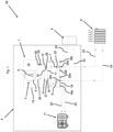
- Fig. 1 shows a heating or cooling system 29 that comprises a hybrid system 2.
- the hybrid system 2 comprises a combustion appliance unit 1 and a heat pump unit 11 that is fluidically connected to the combustion appliance unit 1.
- the combustion appliance unit 1 comprises a combustion appliance device 3 comprising a heat exchanger 4 for exchanging heat between a heat source 5 of the combustion appliance device 3 and a fluid.
- the combustion appliance device 3 can be a gas boiler. In said case the heat source 5 is combusted fuel gas that is combusted in the burner chamber of the combustion appliance device 3.
- the combustion appliance unit 1 comprises an outlet valve 6 and an inlet valve 7. Both valves are configured as 3/2 way valves.
- the outlet valve 6 is used to discharge fluid to a first load 8 and a second load 9.
- the inlet valve 7 is used for controlling the inlet of the fluid coming from the first load 8 and the second load 9.
- the combustion appliance unit 1 also comprises a fluid distributor 10 for distributing the fluid.
- the fluid distributor 10 is fluidically connected to the heat exchanger 4, the inlet valve 6 and the outlet valve 7. Additionally, the fluid distributor 10 is fluidically connected to a heat pump unit 11 of the hybrid system 2. Thus, the fluid distributor 10 is used to distribute the fluid between the components of the heating or cooling system 29, namely the heat pump unit 11, the heat exchanger, the first load 8 and the second load 9.
- the fluid distributor 10 has an inlet 14 by means of which fluid coming from the heat exchanger 4 is inserted into a non-shown cavity of the fluid distributor 10. Further, the fluid distributor 10 has a further inlet 17 by means of which fluid that comes from the inlet valve 7 is inserted. Additionally, the fluid distributor 10 has heat pump inlet 27 by means of which fluid coming from the heat pump 11 is inserted into the cavity of the fluid distributor 10.
- the fluid distributor 10 has three outlets by means of which fluid medium that is arranged in the cavity of the fluid distributor 10 can flow out of the fluid distributor 10. Specifically, the fluid distributor 10 comprises an outlet 15 by means of which the fluid flows towards the heat exchanger 4 and a further outlet 16 by means of which the fluid flows towards the outlet valve 6. Additionally, the fluid distributor 10 comprises a heat pump outlet 28 by means of which the fluid flows towards the heat pump 11.
- the fluid distributor 10 is arranged between the heat exchanger 4 and the valve 6, 7 in a fluid path of the fluid medium.
- the fluid path includes the outlet of the heat exchanger 4 and the inlet 14 of the fluid distributor 10. Additionally, the fluid path includes the outlet 16 of the medium collector 10 and the outlet valve 6.
- the fluid path of the fluid also includes the inlet valve 7, the further inlet 17 of the fluid distributor 10, the further outlet 15 of the fluid distributor 10 and the inlet of the heat exchanger 4.
- the heating or cooling system 29 comprises two loads, namely a first load 8 and a second load 9.
- the combustion appliance unit 1 comprises a first connector 20a and second connector 20b that are fluidically connected to the first load 8.
- the first connector 20a is arranged downstream the outlet valve 6 and the second connector 20b is arranged upstream the inlet valve 7.
- the first connector 20a and the second connector 20b are connected to the first load 8 by means of first load lines 23.
- the first load 8, the first load lines 23, the first connector 20a, the second connector 20b, the outlet valve 6, the inlet valve 7 and the fluid distributor 10 form a first load circuit.
- the combustion appliance unit 1 comprises a third connector 20c and a fourth connector 20d that are fluidcally connected to the second load 9.
- the third connector 20c and the fourth connector 20d are fluidically connector to the second load by means of second load lines 24.
- the second load 9, the second load lines 24, the third connector 20c, the fourth connector 20d, the outlet valve 6, the inlet valve 7 and the fluid distributor 10 form a second load circuit.
- the first load 8 is a water tank comprising water which is heated or cooled by the fluid flowing in the first load lines 23.
- the second load 9 is a radiator by means of which a room is heated or cooled.
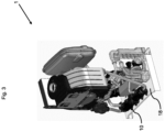
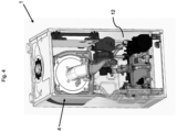
- Figure 3 shows a part of a combustion appliance unit 1 from a first perspective and fig. 4 shows a part of the combustion appliance unit from a second perspective.
- the embodiment shown in fig. 4 differs from the embodiment shown in fig. 3 in that it shows a part of the housing 12 of the combustion appliance unit 1.
- the fluid distributor 18 is arranged on the bottom side 18 of the housing 12.
- Fig. 3 and 4 show the embodiment in which comprises a further heat exchanger 21.
Landscapes
- Engineering & Computer Science (AREA)
- Physics & Mathematics (AREA)
- Thermal Sciences (AREA)
- Chemical & Material Sciences (AREA)
- Combustion & Propulsion (AREA)
- Mechanical Engineering (AREA)
- General Engineering & Computer Science (AREA)
- Steam Or Hot-Water Central Heating Systems (AREA)
Abstract
The invention relates to a combustion appliance unit (1) for a hybrid system (2), the combustion appliance unit (1) comprising:
a combustion appliance device (3) comprising a heat exchanger (4) for exchanging heat between a heat source (5) of the combustion appliance device (3) and a fluid,
at least one valve (6, 7), which is fluidically connectable to at least one load (8, 9),
a fluid distributor (10), which is fluidically connected to the heat exchanger (4) and the at least one valve (6, 7) and fluidically connectable to a heat pump unit (11),
characterized in that,
the fluid distributor (10) is arranged between the heat exchanger (4) and the at least one valve (6, 7) in a fluid path of the fluid.
a combustion appliance device (3) comprising a heat exchanger (4) for exchanging heat between a heat source (5) of the combustion appliance device (3) and a fluid,
at least one valve (6, 7), which is fluidically connectable to at least one load (8, 9),
a fluid distributor (10), which is fluidically connected to the heat exchanger (4) and the at least one valve (6, 7) and fluidically connectable to a heat pump unit (11),
characterized in that,
the fluid distributor (10) is arranged between the heat exchanger (4) and the at least one valve (6, 7) in a fluid path of the fluid.
Description
- The invention relates to a combustion appliance unit for a hybrid system. The invention further relates to a hybrid system comprising such a combustion appliance unit and a heating or cooling system comprising such a combustion appliance unit. Additionally, the invention relates to the use of a combustion appliance unit in a hybrid system or a heating or cooling system.
- Heat pumps become more and more popular for heating or cooling of houses, also in addition to a combustion appliance like a boiler. Using a heat pump alongside a combustion appliance is referred to as a 'hybrid system'. Typically, the term hybrid system describes fitting a heat pump alongside a natural gas, LPG or oil boiler. Such hybrid systems comprise a heat pump and a combustion appliance unit that comprises a combustion appliance device for heating a liquid like water. Additionally, the hybrid systems comprise a fluid distributor that is fluidically connected to the combustion appliance unit and to the heat pump unit.
- The fluid distributor is in direct fluid connection with a central heating system. That means, the fluid distributor is arranged between a load of the central heating system and the heat pump in a fluid path of the fluid and is arranged outside of the combustion appliance unit. Additionally, a domestic heating system is in direct fluid connection with the combustion appliance unit.
- Such hybrid systems comprising a combustion appliance unit and a common heat pump require additional installation space. This installation space is not always available, in particular in cases where an already existing boiler needs to be replaced. Additionally, the installation of said hybrid systems is time consuming as there exist a plurality of fluid connections that have to be connected by the installer.
- The object of the invention is therefore to provide a hybrid system that does not need much installation space and that can be installed fast by an installer.
- The object is solved by a combustion appliance unit for a hybrid system, the combustion appliance unit comprising:
- a combustion appliance device comprising a heat exchanger for exchanging heat between a heat source of the combustion appliance device and a fluid,
- at least one valve, which is fluidically connectable to at least one load,
- a fluid distributor, which is fluidically connected to the heat exchanger and the at least one valve and fluidically connectable to a heat pump unit,
- characterized in that,
- the fluid distributor is arranged between the heat exchanger and the at least one valve in a fluid path of the fluid.
- It was realized that the installation space of the hybrid system can be reduced by rearranging the fluid distributor in the fluid path of the hybrid system. In particular, it was realized that it is possible to arrange the fluid distributor close to the combustion appliance device by arranging the fluid distributor between the heat exchanger and the at least one valve. This reduces the installation space as it is not necessary anymore to place the fluid distributor outside the combustion appliance unit as it is explained below more in detail. The aforementioned arrangement of the fluid distributor also reduces the effort for the installer to install the hybrid system. This results as fluid distributor can be connected to the heat exchanger and the valves when the combustion appliance unit is assembled. This results in less effort for the installer when the installer assembles the hybrid system or the heating or cooling system.
- According to the understanding of the invention a "combustion appliance device" is any device that is capable to combust fuel. The fuel can be oil, natural gas, propane, hydrogen or a mixture of hydrogen and another fuel, such as natural gas or propane. However, it is also possible that the fuel is in solid state. In said case the fuel can be coal, pellets or the same. The device can be a boiler and/or comprise a burner, a burner chamber and the heat exchanger. Additionally, the device, in particular boiler, can comprise valves, at least one control unit and a control panel.
- The fluid can be any medium in a gaseous or liquid state, which enables the heat transfer between the components of the heating or cooling system, i.e. the combustion appliance device, the heat pump and the at least one load. In particular, the fluid can be water. The heating or cooling system can be operated in a cooling mode or in a heating mode. Thereto, the heat pump unit is operated in the corresponding mode. In the cooling mode the at least one load is cooled whereas in the heating mode the at least one load is heated.
- The heat pump unit can be a ground source heat pump or an air source heat pump. Additionally or alternatively, the heat pump can be a split unit or a monobloc unit. The heat pump can be configured to heat or cool the fluid medium. Thereto, the heat pump comprises a heat pump heat exchanger in which the heat exchange between the fluid medium and the refrigerant of the heat pump occurs.
- A "fluidic connection" between two or more components means that the components are connected in such manner that a fluid, in particular a liquid, can flow from one component to the other component. A "fluid path" is the path that the fluid medium flows within the heating or cooling system. As is discussed below more in detail the heating or cooling system comprises several circuits. Said circuits define the fluid path of the fluid medium.
- The fluid distributor is used to collect and distribute the fluid that flows between the different components of the heating or cooling system. In particular, the fluid distributor is a hydronic or hydraulic distributor by means of which the fluid, in particular water, as an energy carrier, is distributed between the heat pump unit, the combustion appliance device and at least one load, in particular several loads. The terms hydraulic and hydronic are used as synonymously. The fluid distributor is fluidly connected with the heat pump unit and the combustion appliance device to receive fluid medium from the heat pump unit and the combustion appliance device that is to be distributed to the one or more loads of the heating or cooling system. The fluid distributor has a cavity for receiving the fluid and several inlets and outlets that are fluidically connected to the components of the heating or cooling system.
- According to an embodiment the combustion appliance unit can comprise a housing and the medium collector is arranged inside an inner space of the housing. Thus, the installation space needed for the combustion appliance unit and thus for the hybrid system is small.
- The housing can be formed by one or more side panels. The side panels can comprise at least one of steel, aluminium, a polymeric, in particular a thermoplastic material, and a composite material or can be made of steel, aluminium, a polymeric, in particular a thermoplastic material, and a composite material. Steel provides the side panels with strength. The aluminium, the polymeric, in particular the thermoplastic material, and the composite material may be used to reduce the noise generated by the combustion appliance device and reduce the weight of the respective unit.
- In the operational state the side panels cover the inner space of the combustion appliance unit and close off the inner space of the combustion appliance unit to prevent accidental access of by-passers or dust. At least one side panel, in particular two side panels can be removed or opened to provide access to the inside of the combustion appliance unit. This allows maintenance personnel to access the combustion appliance unit without the need to remove the combustion appliance device. Depending on the circumstances, the maintenance personnel may access from one side or the other side. In case one side panel can be removed for servicing of components of the combustion appliance unit, the combustion appliance unit can be provided selectively accessible from the left-hand side or the right-hand side in an installation position.
- The side panels are provided at opposite sides of the combustion appliance unit to shield the interior of the combustion appliance unit comprising the medium collector, the combustion application device and other components. In particular, the side panels can be opposite to each other regarding a plane comprising a central body axis of the combustion appliance unit.
- The fluid distributor can comprise an inlet for receiving fluid from the heat exchanger and an outlet for discharging fluid to the heat exchanger of the combustion appliance device. Additionally, the fluid distributor can comprise a heat pump inlet for receiving fluid from the heat pump unit and a heat pump outlet for discharging fluid to the heat pump unit. Thus, the same fluid distributor can be fluidically connected to the combustion appliance device and the heat pump unit.
- The fluid distributor can comprise a further outlet for discharging fluid to an outlet valve. The outlet valve is used to discharge fluid to at least one load, in particular to several loads. Further, the fluid distributor can comprise a further inlet for inletting fluid medium from an inlet valve. The inlet valve is used to receive fluid from at least one load, in particular from several loads. Thus, the fluid distributor has a simple structure and is connected to the valves, the heat pump unit and the combustion appliance device in a simple manner.
- The inlet and/or the outlet valve can be a 3/2 valve. Thus, it is possible to control the flow rate of the discharged fluid medium in an easy manner. In particular, it is possible to control the flow rate that flows to each of the loads, respectively. Additionally, it is possible to control the flow rate that flows into the fluid distributor. In particular, it is possible to control the flow rate from each of the circuits, which are discussed below more in detail, into the fluid distributor.
- The housing can comprise a housing side, in particular a side panel. Said housing side can comprise at least one connector for fluidically connecting the combustion appliance device to at least one load and at least one further connector for fluidically connecting the combustion appliance device to the heat pump unit. As the at least one connector and the at least one further connector are at arranged at the same housing side, the installation effort for the installer to connect said connector to the load circuits and to the heat pump is low.
- According to an embodiment the combustion appliance unit can comprise a further heat exchanger that is arranged downstream the at least one valve and/or upstream the at least one connector by means of which the at least one valve and a load are fluidically connected to each other. Thus, the further heat exchanger can be arranged between the at least one valve and the at least one connector in the fluid path of the fluid. Additionally or alternatively, the further heat exchanger can be arranged inside the inner space of the combustion appliance unit resulting in a compact combustion appliance unit. By providing the further heat exchanger it is possible to provide a heating or cooling system in which a system boiler can be used. In said embodiment the first load circuit comprises a domestic water tank.
- The combustion appliance unit can comprise a pump that is arranged between the medium collector and the heat exchanger in the fluid path of the fluid. Said pump can be arranged in the inner space of the combustion appliance unit. The pump is used for pumping the fluid in a combustion appliance circuit. Said combustion appliance circuit can comprise the pump, the fluid distributor and the heat exchanger of the combustion appliance device. The combustion appliance circuit can comprise combustion appliance lines by means of which the heat exchanger is fluidically connected to the fluid distributor. The combustion appliance circuit is arranged in the inner space of the combustion appliance unit.
- The combustion appliance can comprise a further pump for pumping the fluid from the at least one load to the medium collector. The further pump can be arranged in the inner space of the combustion appliance unit. Additionally, the further pump can be configured to pump fluid coming from the first load to the fluid distributor and to pump fluid coming from the second load to the fluid distributor. Thus, the same pump is used for pumping fluid through two circuits.
- Specifically, the further pump can be configured to pump a fluid through a first load circuit. The first load circuit comprises the fluid distributor, the further pump, a first connector, the inlet valve, the outlet valve, a second connector, first load pipes and the first load. Additionally, the further pump can be configured to pump fluid medium through a second load circuit. The second load circuit comprises the fluid distributor, the further pump, a third connector, the inlet valve, the outlet valve, a fourth connector, second load pipes and the second load.
- According to an aspect of the invention, a hybrid system is provided. The hybrid system comprises a heat pump unit for cooling or heating the fluid. The heat pump unit is fluidically connected to the combustion appliance unit. The heat pump system can comprise a heat pump circuit. The heat pump circuit can comprise the fluid distributor, the heat pump inlet connector and the heat pump outlet connector and the heat pump exchanger. Additionally, the heat pump circuit can comprise heat pump lines by means of which the heat pump unit is fluidically connected to the combustion appliance unit.
- The heat pump heat exchanger is part of the heat pump unit and may be a refrigerant-destination medium heat exchanger. The destination medium is the fluid discussed above. The refrigerant is a medium used by the heat pump unit to transfer heat. The heat pump heat exchanger is fluidly connected to and part of a refrigerant circulation system to receive warmed (or cooled) refrigerant for warming (or cooling) the fluid medium. The heat pump heat exchanger is also fluidly connected to and part of the refrigeration circulation system to discharge refrigerant from the heat pump heat exchanger. The discharged refrigerant is used in the remainder of the refrigerant circulation system to be reheated (or re-cooled). The refrigerant circulation system is part of the heat pump unit.
- As is evident from above, the fluid distributor is part of all circuits of the hybrid system resulting in a simple fluid flow distribution system within the heating or cooling system.
- According to an embodiment the combustion appliance unit comprises a control unit. The control unit is used for controlling the heat pump unit and/or the components of the combustion appliance unit. The control unit may be arranged in the inner space of the combustion appliance unit. The control unit may be configured to control the inlet valve and/or the outlet valve. The control unit comprise one or more processors or be a processor. Alternatively, the control unit can be a control board circuit or can be part of a control board circuit. Any or all sensors, pumps, actuators, room units of the heating or cooling system can be connected the controller unit, wirelessly or via electric lines.
- According to an aspect of the invention a heating or cooling system is provided. The heating or cooling system comprising at least one load that is fluidically connected to an inventive combustion appliance unit or is fluidically connected to an inventive hybrid system.
- The heating or cooling system can comprise several loads, namely a first load and a second load. The first load can be part of a first load circuit, which can be a domestic load circuit. The domestic load circuit can be part of a domestic heating system and can provide hot water for e.g. showering. The first load circuit can comprise first load pipes by means of which the first load is fluidically connected to the combustion appliance unit.
- The second load can be part of a second load circuit, which can be a central load circuit. The central load circuit can be part of a central heating system and can comprise a radiator for heating a room and/or can be a floor heating. The second load circuit can comprise second load pipes by means of which the second load is fluidically connected to the combustion appliance unit. The heating or cooling system can comprise more load circuits. In particular, the heating or cooling system can comprise one or more central load circuits and/or one or more domestic load circuits.
- An inventive combustion appliance unit can be used in a hybrid system comprising a heat pump unit. In said case the combustion appliance unit can be fluidically connected to the heat pump and/or to at least one load, in particular load circuit.
- In the figures, the subject-matter of the invention is schematically shown, wherein identical or similarly acting elements are usually provided with the same reference signs.
- Figure 1
- shows a heating or cooling system with an inventive combustion appliance unit according to a first embodiment.
- Figure 2
- shows a heating or cooling system with an inventive combustion appliance unit according to a second embodiment.
- Figure 3
- shows a part of a combustion appliance unit from a first perspective view.
- Figure 4
- shows a part of a combustion appliance unit with housing from a second perspective view.
-
Fig. 1 shows a heating orcooling system 29 that comprises ahybrid system 2. Thehybrid system 2 comprises a combustion appliance unit 1 and aheat pump unit 11 that is fluidically connected to the combustion appliance unit 1. The combustion appliance unit 1 comprises acombustion appliance device 3 comprising aheat exchanger 4 for exchanging heat between aheat source 5 of thecombustion appliance device 3 and a fluid. Thecombustion appliance device 3 can be a gas boiler. In said case theheat source 5 is combusted fuel gas that is combusted in the burner chamber of thecombustion appliance device 3. - Additionally, the combustion appliance unit 1 comprises an
outlet valve 6 and aninlet valve 7. Both valves are configured as 3/2 way valves. Theoutlet valve 6 is used to discharge fluid to afirst load 8 and asecond load 9. Theinlet valve 7 is used for controlling the inlet of the fluid coming from thefirst load 8 and thesecond load 9. - The combustion appliance unit 1 also comprises a
fluid distributor 10 for distributing the fluid. Thefluid distributor 10 is fluidically connected to theheat exchanger 4, theinlet valve 6 and theoutlet valve 7. Additionally, thefluid distributor 10 is fluidically connected to aheat pump unit 11 of thehybrid system 2. Thus, thefluid distributor 10 is used to distribute the fluid between the components of the heating orcooling system 29, namely theheat pump unit 11, the heat exchanger, thefirst load 8 and thesecond load 9. - The
fluid distributor 10 has aninlet 14 by means of which fluid coming from theheat exchanger 4 is inserted into a non-shown cavity of thefluid distributor 10. Further, thefluid distributor 10 has afurther inlet 17 by means of which fluid that comes from theinlet valve 7 is inserted. Additionally, thefluid distributor 10 hasheat pump inlet 27 by means of which fluid coming from theheat pump 11 is inserted into the cavity of thefluid distributor 10. - The
fluid distributor 10 has three outlets by means of which fluid medium that is arranged in the cavity of thefluid distributor 10 can flow out of thefluid distributor 10. Specifically, thefluid distributor 10 comprises anoutlet 15 by means of which the fluid flows towards theheat exchanger 4 and afurther outlet 16 by means of which the fluid flows towards theoutlet valve 6. Additionally, thefluid distributor 10 comprises aheat pump outlet 28 by means of which the fluid flows towards theheat pump 11. - The
fluid distributor 10 is arranged between theheat exchanger 4 and thevalve heat exchanger 4 and theinlet 14 of thefluid distributor 10. Additionally, the fluid path includes theoutlet 16 of themedium collector 10 and theoutlet valve 6. The fluid path of the fluid also includes theinlet valve 7, thefurther inlet 17 of thefluid distributor 10, thefurther outlet 15 of thefluid distributor 10 and the inlet of theheat exchanger 4. - The combustion appliance unit 1 comprises a
housing 12 that delimits aninner space 13 of the combustion appliance unit 1. Thefluid distributor 10 is arranged in theinner space 13 of the combustion appliance unit 1. The combustion appliance unit 1 comprises ahousing side 18, in particular a bottom side, that holdsseveral connectors further connectors - A first
further connector 19a and a secondfurther connector 19b are used to fluidically connect the combustion appliance unit 1 to theheating pump 11. In particular, the firstfurther connector 19a and the secondfurther connector 19b are fluidically connected to aheat pump line 25, respectively. Thus, a heat pump circuit is created comprising theheat pump unit 11, theheat pump lines 25 and thefluid distributor 10. Thehybrid system 2 comprises a non-shown heat pump used for pumping fluid within the heat pump circuit. - The heating or
cooling system 29 comprises two loads, namely afirst load 8 and asecond load 9. The combustion appliance unit 1 comprises afirst connector 20a andsecond connector 20b that are fluidically connected to thefirst load 8. Thefirst connector 20a is arranged downstream theoutlet valve 6 and thesecond connector 20b is arranged upstream theinlet valve 7. Thefirst connector 20a and thesecond connector 20b are connected to thefirst load 8 by means offirst load lines 23. Thefirst load 8, thefirst load lines 23, thefirst connector 20a, thesecond connector 20b, theoutlet valve 6, theinlet valve 7 and thefluid distributor 10 form a first load circuit. - Additionally, the combustion appliance unit 1 comprises a
third connector 20c and afourth connector 20d that are fluidcally connected to thesecond load 9. Thethird connector 20c and thefourth connector 20d are fluidically connector to the second load by means ofsecond load lines 24. Thesecond load 9, thesecond load lines 24, thethird connector 20c, thefourth connector 20d, theoutlet valve 6, theinlet valve 7 and thefluid distributor 10 form a second load circuit. - The
outlet valve 6 is configured such that it distributes the fluid via thefirst connector 20a to thefirst load line 23 and via thethird connector 20c to thesecond load line 24. Theinlet valve 7 is configured such that it combines the fluid coming from thesecond connector 20b being in fluid connection with thefirst load line 23 and thefourth connector 20d being in fluid connection with thesecond load line 24. - The combustion appliance unit 1 comprises a
pump 30 used for circulating heat medium within a combustion appliance circuit comprising combustion appliance lines 26. Said circuit comprises thefluid distributor 10, thepump 30 and theheat exchanger 4. The combustion appliance 1 also comprises afurther pump 22. Said further pump 22 is used for circulating heat medium within the first load circuit and the second load circuit. - The
first load 8 is a water tank comprising water which is heated or cooled by the fluid flowing in thefirst load lines 23. Thesecond load 9 is a radiator by means of which a room is heated or cooled. -
Figure 2 shows a heating orcooling system 29 with an inventive combustion appliance unit 1 according to a second embodiment. Said embodiment differs from the embodiment shown infigure 1 in that afurther heat exchanger 21 is provided. Thefurther heat exchanger 21 is arranged such that fluid passes through thefurther heat exchanger 21 before the fluid leaves the combustion appliance unit 1 via thefirst connector 20a. Additionally, thefurther heat exchanger 21 is arranged such that the fluid coming fromsecond connector 20b flows through theheat exchanger 21 before it enters theinlet valve 7. In other words, thefurther heat exchanger 21 is arranged downstream theoutlet valve 6 and/ upstream theinlet valve 7. - A further difference in this embodiment is that the
first load 8 is domestic water consumer like a shower. That means, in this embodiment there is no need for providing a water tank. -
Figure 3 shows a part of a combustion appliance unit 1 from a first perspective andfig. 4 shows a part of the combustion appliance unit from a second perspective. The embodiment shown infig. 4 differs from the embodiment shown infig. 3 in that it shows a part of thehousing 12 of the combustion appliance unit 1. Thefluid distributor 18 is arranged on thebottom side 18 of thehousing 12.Fig. 3 and4 show the embodiment in which comprises afurther heat exchanger 21. -
- 1
- Combustion appliance unit
- 2
- Hybrid system
- 3
- Combustion appliance device
- 4
- Heat exchanger
- 5
- Heat source
- 6
- Outlet valve
- 7
- Inlet valve
- 8
- First load
- 9
- Second load
- 10
- Fluid distributor
- 11
- Heat pump unit
- 12
- Housing
- 13
- Inner space
- 14
- Inlet
- 15
- Outlet
- 16
- Further outlet
- 17
- Further inlet
- 18
- bottom side
- 19a
- first further connector
- 19b
- second further connector
- 20a
- first connector
- 20b
- second connector
- 20c
- third connector
- 20d
- fourth connector
- 21
- Further heat exchanger
- 22
- Further pump
- 23
- first load line
- 24
- second load line
- 25
- heat pump line
- 26
- combustion appliance line
- 27
- heat pump inlet
- 28
- heat pump outlet
- 29
- Heating or cooling system
- 30
- Pump
Claims (15)
- Combustion appliance unit (1) for a hybrid system (2), the combustion appliance unit (1) comprising:a combustion appliance device (3) comprising a heat exchanger (4) for exchanging heat between a heat source (5) of the combustion appliance device (3) and a fluid,9), at least one valve (6, 7), which is fluidically connectable to at least one load (8,a fluid distributor (10), which is fluidically connected to the heat exchanger (4) and the at least one valve (6, 7) and fluidically connectable to a heat pump unit (11),characterized in that,the fluid distributor (10) is arranged between the heat exchanger (4) and the at least one valve (6, 7) in a fluid path of the fluid.
- Combustion appliance unit (1) according to claim 1, characterized in that the combustion appliance unit (1) comprises a housing (12) and the fluid distributor (10) is arranged inside an inner space (13) of the housing (12).
- Combustion appliance unit (1) according to claim 1 or 2, characterized in thata. the fluid distributor (10) comprises an inlet (14) for receiving fluid from the heat exchanger (4) and an outlet for (15) discharging fluid to the heat exchanger (4) and/or in thatb. the fluid distributor (10) comprises a heat pump inlet (27) for receiving fluid from the heat pump unit (11) and a heat pump outlet (27) for discharging fluid to the heat pump unit (11).
- Combustion appliance unit (1) according to at least one of the claims 1 to 3, characterized in thata. the at least one valve is an outlet valve (6) for discharge fluid to at least one load (8, 9), in particular to several loads (8, 9), and/or in thatb. the at least one valve is an inlet valve (7) for receiving fluid from at least one load (8, 9), in particular from several loads (8, 9).
- Combustion appliance unit (1) according to claim 4, characterized in that the fluid distributor (10) comprises a further outlet (16) for discharging fluid to the outlet valve (6) and a further inlet (17) for receiving fluid from the inlet valve (7).
- Combustion appliance unit (1) according to at least one of the claims 2 to 5, characterized in that a housing side (18) comprises at least one connector (20a, 20b, 20c, 20d) for fluidically connecting the combustion appliance device (3) to at least one load (8, 9) and at least one further connector (19a, 19b) for fluidically connecting the combustion appliance device (3) to the heat pump unit (11).
- Combustion appliance unit (1) according to at least one of the claims 1 to 6, characterized in that the combustion appliance unit (1) comprises a further heat exchanger (21) that is arranged downstream the at least one valve (6, 7) and/or upstream at least one connector (20a, 20b, 20c, 20d) by means of which the at least one valve (6, 7) and a load (8, 9) are fluidically connected to each other.
- Combustion appliance unit (1) according to at least one of the claims 1 to 7, characterized in thata. the combustion appliance unit (1) comprises a pump (22) that is arranged between the fluid distributor (10) and the heat exchanger (4) in the fluid path of the fluid and/or in thatb. a combustion appliance circuit (26) comprising combustion appliance lines by means of which the heat exchanger (4) is fluidically connected to the fluid distributor (10).
- Combustion appliance unit (1) according to at least one of the claims 1 to 8, characterized in that the combustion appliance unit (1) comprises a further pump (22) for pumping the fluid from the at least one load (8, 9) to the fluid distributor (10).
- Combustion appliance unit (1) according to claim 9, characterized in thata. the further pump (22) is arranged in the inner space (13) of the combustion appliance unit (1) and/or in thatb. the further pump (22) is configured to pump fluid from a first load (8) to the fluid distributor (10) and to pump fluid medium from a second load (9) to the fluid distributor (10).
- Hybrid system (2) comprising a combustion appliance unit (1) according to at least one of the claims 1 to 10 and a heat pump unit (11) for cooling or heating the fluid wherein the heat pump unit (11) is fluidically connected to the combustion appliance unit (1).
- Hybrid system (2) according to claim 11, characterized in that the hybrid system (2) comprises a heat pump circuit comprising heat pump lines (25) by means of which the heat pump unit (11) is fluidically connected to the combustion appliance unit (1), wherein the fluid distributor (10) is part of the heat pump circuit (23).
- Heating or cooling system (29) comprising at least one load (8, 9) that is fluidically connected to the combustion appliance unit (1) according to at least one of the claims 1 to 10 or connected to the hybrid system (2) according to claim 11 or 12.
- Heating or cooling system (29) according to claim 13, characterized in thata. the first load (8) is part of a domestic heating system and/or in thatb. the second load (9) is part of a central heating system and/or in thatc. the heating or cooling system (29) comprises a first load circuit with first load circuit pipes (23) by means of which the first load (8) is fluidically connected to the combustion appliance unit (1), wherein the fluid distributor (10) is part of the first load circuit, and/or in thatd. the heating or cooling system (29) comprises a second load with second load circuit pipes (24) by means of which the second load (9) is fluidically connected to the combustion appliance unit (1), wherein the fluid distributor (10) is part of the second load circuit (23).
- Use of a combustion appliance unit (1) according to at least one of the claims 1 to 10 in a hybrid system (2) comprising a heat pump unit (11), in particular a hybrid system according to claim 11 or 12, or in a heating or cooling system (29) according to claim 13 or 14.
Priority Applications (2)
| Application Number | Priority Date | Filing Date | Title |
|---|---|---|---|
| EP23203419.9A EP4538612A1 (en) | 2023-10-13 | 2023-10-13 | Combustion appliance unit for a hybrid system |
| PCT/EP2024/078389 WO2025078424A1 (en) | 2023-10-13 | 2024-10-09 | Combustion appliance unit for a hybrid system |
Applications Claiming Priority (1)
| Application Number | Priority Date | Filing Date | Title |
|---|---|---|---|
| EP23203419.9A EP4538612A1 (en) | 2023-10-13 | 2023-10-13 | Combustion appliance unit for a hybrid system |
Publications (1)
| Publication Number | Publication Date |
|---|---|
| EP4538612A1 true EP4538612A1 (en) | 2025-04-16 |
Family
ID=88412269
Family Applications (1)
| Application Number | Title | Priority Date | Filing Date |
|---|---|---|---|
| EP23203419.9A Withdrawn EP4538612A1 (en) | 2023-10-13 | 2023-10-13 | Combustion appliance unit for a hybrid system |
Country Status (2)
| Country | Link |
|---|---|
| EP (1) | EP4538612A1 (en) |
| WO (1) | WO2025078424A1 (en) |
Citations (6)
| Publication number | Priority date | Publication date | Assignee | Title |
|---|---|---|---|---|
| EP2159495A1 (en) * | 2008-08-25 | 2010-03-03 | Honeywell Technologies Sarl | A controller for a temperature control system |
| ITMI20112252A1 (en) * | 2011-12-13 | 2013-06-14 | Caleffi Spa | HYBRID SYSTEM OF HEATING AND / OR COOLING |
| US20130248609A1 (en) * | 2010-12-08 | 2013-09-26 | Daikin Europe N.V. | Heating system and method for controlling a heating system |
| WO2014002133A1 (en) * | 2012-06-26 | 2014-01-03 | 三菱電機株式会社 | Heat-pump type hot water supply/heating system |
| EP2700883B1 (en) * | 2012-08-22 | 2017-12-13 | BDR Thermea Group | Hybrid system for producing domestic hot water with a heat pump and a boiler |
| EP3767199A1 (en) * | 2019-07-12 | 2021-01-20 | BDR Thermea Group | Water heating device with heat pump |
-
2023
- 2023-10-13 EP EP23203419.9A patent/EP4538612A1/en not_active Withdrawn
-
2024
- 2024-10-09 WO PCT/EP2024/078389 patent/WO2025078424A1/en active Pending
Patent Citations (6)
| Publication number | Priority date | Publication date | Assignee | Title |
|---|---|---|---|---|
| EP2159495A1 (en) * | 2008-08-25 | 2010-03-03 | Honeywell Technologies Sarl | A controller for a temperature control system |
| US20130248609A1 (en) * | 2010-12-08 | 2013-09-26 | Daikin Europe N.V. | Heating system and method for controlling a heating system |
| ITMI20112252A1 (en) * | 2011-12-13 | 2013-06-14 | Caleffi Spa | HYBRID SYSTEM OF HEATING AND / OR COOLING |
| WO2014002133A1 (en) * | 2012-06-26 | 2014-01-03 | 三菱電機株式会社 | Heat-pump type hot water supply/heating system |
| EP2700883B1 (en) * | 2012-08-22 | 2017-12-13 | BDR Thermea Group | Hybrid system for producing domestic hot water with a heat pump and a boiler |
| EP3767199A1 (en) * | 2019-07-12 | 2021-01-20 | BDR Thermea Group | Water heating device with heat pump |
Also Published As
| Publication number | Publication date |
|---|---|
| WO2025078424A1 (en) | 2025-04-17 |
Similar Documents
| Publication | Publication Date | Title |
|---|---|---|
| AU2017310515B2 (en) | Hydro-furnaces and related methods for vehicles | |
| US5950575A (en) | Hydronic manifold | |
| CN101371080B (en) | Devices for distributing and regulating heat carriers from heat and/or heat sinks | |
| US8743542B2 (en) | Apparatus and method for cooling of a substantially closed space with recirculation air | |
| US11300301B2 (en) | Manifold, a buffer tank comprising the manifold, and a method for operating a heat exchange system | |
| EP4108996A1 (en) | Modular heat station | |
| EP4108998B1 (en) | Monolithic heating station with by-pass | |
| US7191789B2 (en) | Transition adaptor and component modules for hydronic heating | |
| CZ256097A3 (en) | Hydraulic structural group for a combined apparatus for heating and service water | |
| WO2025078424A1 (en) | Combustion appliance unit for a hybrid system | |
| US9366447B2 (en) | Service water heating unit | |
| EP3084316B1 (en) | Heat exchanger apparatus | |
| CN115597099A (en) | Interconnecting guide rail for heating station | |
| LU505389B1 (en) | Method for commissioning a hybrid system | |
| JP5811328B2 (en) | Hot water system | |
| EP4459193A1 (en) | Hydraulic module with optional plates and heating device equipped with a hydraulic module | |
| CN120936836A (en) | Heating system with heat pump for internal installation | |
| CZ37270U1 (en) | A modular system for heating and hot water preparation | |
| EP4677273A1 (en) | Heat pump coupling frame kit with an aligned connector set | |
| WO2024188438A1 (en) | Heat pump coupling frame kit with an aligned connector set | |
| EP3835665A1 (en) | Tank and method for operating a thermal installation | |
| WO2024240331A1 (en) | Heat pump coupling frame kit with an aligned connector set | |
| BG5261U1 (en) | Integrated vertical device for heating/cooling and domestic hot water production | |
| WO2024188428A1 (en) | Heat pump coupling frame kit with a distributor | |
| WO2024188423A1 (en) | Hybrid heat pump frame kit |
Legal Events
| Date | Code | Title | Description |
|---|---|---|---|
| PUAI | Public reference made under article 153(3) epc to a published international application that has entered the european phase |
Free format text: ORIGINAL CODE: 0009012 |
|
| STAA | Information on the status of an ep patent application or granted ep patent |
Free format text: STATUS: THE APPLICATION HAS BEEN PUBLISHED |
|
| AK | Designated contracting states |
Kind code of ref document: A1 Designated state(s): AL AT BE BG CH CY CZ DE DK EE ES FI FR GB GR HR HU IE IS IT LI LT LU LV MC ME MK MT NL NO PL PT RO RS SE SI SK SM TR |
|
| STAA | Information on the status of an ep patent application or granted ep patent |
Free format text: STATUS: THE APPLICATION IS DEEMED TO BE WITHDRAWN |
|
| 18D | Application deemed to be withdrawn |
Effective date: 20251017 |