EP4538600A1 - Oven with partially extractable cooking module on fixed tracks - Google Patents
Oven with partially extractable cooking module on fixed tracks Download PDFInfo
- Publication number
- EP4538600A1 EP4538600A1 EP24020308.3A EP24020308A EP4538600A1 EP 4538600 A1 EP4538600 A1 EP 4538600A1 EP 24020308 A EP24020308 A EP 24020308A EP 4538600 A1 EP4538600 A1 EP 4538600A1
- Authority
- EP
- European Patent Office
- Prior art keywords
- oven
- cooking
- module
- fact
- side wall
- Prior art date
- Legal status (The legal status is an assumption and is not a legal conclusion. Google has not performed a legal analysis and makes no representation as to the accuracy of the status listed.)
- Pending
Links
Images




Classifications
-
- F—MECHANICAL ENGINEERING; LIGHTING; HEATING; WEAPONS; BLASTING
- F24—HEATING; RANGES; VENTILATING
- F24C—DOMESTIC STOVES OR RANGES ; DETAILS OF DOMESTIC STOVES OR RANGES, OF GENERAL APPLICATION
- F24C15/00—Details
- F24C15/08—Foundations or supports plates; Legs or pillars; Casings; Wheels
Definitions
- the subject of this invention is an oven with partially extractable cooking module on fixed tracks.
- This invention intends to propose a new and beneficial solution of an oven that significantly facilitates the maintenance and inspection of these and other functional parts, which are grouped closer together, exposed, and easily accessible with respect to conventional and known solutions.
- the proposed cooking oven is especially suitable for community catering, where practicality and ease of use are essential, and it is also essential to carry out frequent routine maintenance in situ, reducing inconvenience in the kitchen and limiting repair times, resulting in lower global costs.
- a metal structural frame is equipped with a first and a second telescopic guide fastened to the sides, in such a way that the first guide is specular and symmetrical with respect to the second guide, and wherein said oven rotary support shelf is fastened in correspondence with the retractable segments at the end opposite to the fastened segments.
- a cooking oven (10, 10a) for community catering composed of a fixed part comprising an outer body (100) functioning as an enclosure and support, and a mobile part comprising a cooking module (101) mounted inside the body and at least partially extractable (EP) by traversing horizontally on fixed tracks (114) and corresponding carriages (115, 116) mounted under the module.
- the cooking module (101) has at least said functional parts (110) which are mounted on a side of the oven chamber (102) to form an equipped side wall (108), accommodated in an open space bounded by the body in the form of a housing (109), and easily accessible at the side with the module partially extracted (EP) for routine maintenance tasks.
- the opposite side is blank (107) and adjacent to the body; consequently, the oven (10, 10a) has a narrower oven chamber (101) that is off-centre with respect to the body (100), having the equipped side wall (108, 109) located to the side, with the functional equipment (110, 110a - 110q) exposed.
- a second variant of the electric convection oven is envisaged with mechanical thermostat control, and including at least one lateral heating element with multi-speed ventilation means, a manual humidifier, manual air inlet valve management means, control means with mechanical relays and contactors.
- a fourth variant of the combined oven is envisaged with multifunction electronic swipe or touch automatic control means, including at least one lateral heating element with multi-speed ventilation means, an upper static heating element with independent manual control, a possible lower static heating element with independent manual control, integrated automatic washing means, a humidification system with humidity percentage management, means for dry, steam, or combined cooking, multiple preloaded cooking programs with personalised management of recipes, control means with electronic power relays of the solid state or SSR type, fan speed control means with an inverter, having for example six speed levels.
- the oven (10) has an oven chamber (102) of standardised capacity, in compliance with European Gastronorm regulations, for example 4 GN 2/1 containers or 8 GN 1/1 containers, or also 4 GN1/1 containers.
- the oven (10) can be installed under a standardised professional kitchen element, for example having a body (100) 800 mm wide and from 700 mm to 900 mm deep.
- the oven can therefore be beneficially integrated in commonly used community catering kitchen equipment.
- the oven (10) is schematically represented with the module (101) partially extracted, to allow routine maintenance tasks, having the functional equipment mounted on an equipped side wall (108) of the oven chamber (102), all on the same side and easily accessible.
- the first figure ( Fig. 8a ) shows the oven individually integrated between kitchen units and appliances of identical height and width, with the body functioning as a support base for a professional hob, a griddle or a grill (118).
- the oven is shown in a multiple configuration, joined to and aligned with identical ovens, being respectively positioned side by side in a horizontal in-line array ( Fig. 8b ) or stacked in a vertical wall-standing or column mounted array ( Fig. 8c ).
- blank side wall of the body (129) refers to a side wall of the body (100) that is closed and without functional parts; by extension, a configuration of a blank side wall wherein, in place of or in combination with said closed side of the body there is an adjacent kitchen unit, or an adjacent wall, with an identical closing effect is construed as included and equivalent in the context of this description.
- the proposed solution principally solves the aforementioned problem of overheating of the body in correspondence with the blank side wall (107) of the module (102, 103) adjoining said blank side wall (129) of the body (100) construed as described above, without incorporating any dedicated device inside it and without obstructing extraction of the module, thus solving the mentioned safety problems in the oven and/or by extension in the adjacent kitchen units and/or in walls adjacent to its side ( Figs. 10 , 11, 12 ).
Landscapes
- Engineering & Computer Science (AREA)
- Chemical & Material Sciences (AREA)
- Combustion & Propulsion (AREA)
- Mechanical Engineering (AREA)
- General Engineering & Computer Science (AREA)
- Electric Stoves And Ranges (AREA)
Abstract
Description
- The subject of this invention is an oven with partially extractable cooking module on fixed tracks.
- The innovation finds special although not exclusive application in the food cooking appliances industry. The proposed solution facilitates the maintenance tasks required during frequent use of an oven, and it is particularly suitable for professional catering or large kitchens for community catering.
- Cooking ovens are well known and widespread in the professional catering sector, being appliances necessary for thermal treatment of foods and for guaranteeing the high quality of the finished food products served. The market offers multiple solutions of ovens suitable for professional catering use. Widely diffused oven solutions include electric static ovens, convection ovens with forced air flow, steam ovens, and combined or hybrid ovens in which different cooking modes can be used independently or simultaneously. Moreover, conventional control solutions of said ovens are known and widely diffused, including more evolved electronic control solutions. Specifically, it is noted that said static convection and combined, also steam type, ovens with mechanical and electronic control, are highly regarded in community catering applications, where they are subject to frequent and intensive use, being simple and quick to use, efficient, and economically priced.
- It is however noted that these ovens are equipped with multiple electrical and/or electromechanical and/ or electronic and/or pneumatic parts and devices that must be frequently inspected, adjusted, serviced or replaced, since they are subject to various degenerative phenomena associated with continuous use, namely wear, breakage, loss of calibration, deformation, and also exhaustion. Merely by way of example, electric heating elements can burn out and must be replaced entirely, or motors and impeller means for forced convection which sometimes break or become noisy due to deformation or axial misalignment, or also pumps and solenoid valves of automatic washing systems, which can become jammed due to irregularities of the electrical supply or built-in protection devices. In all of these cases and many others, it is therefore necessary to work rapidly to solve the problem; notwithstanding, maintenance tasks are usually carried out in uncomfortable conditions. In this context, in professional ovens there are usually only a small number of devices accessible from the front or by moving and/or partially dismantling the appliances in situ, such as the frequent case of a front control panel incorporating display, buttons, and electronic control boards on the rear. In the majority of cases however, to access the various parts responsible for operation of the oven for inspection or replacement purposes, the appliance must be completely removed and/or transported to a specialised workshop, since the control equipment is integrated in various parts of the appliance and cannot be reached directly.
- More generally, there is rising demand in the field of professional catering for appliances capable of facilitating the daily work of operators, making it more convenient and/or faster and/or safer and/or more intuitive. For example, concerning cooking ovens there are multiple known solutions to make food thermal treatment cycles automatic or semi-automatic, while integrated automatic washing solutions are highly desirable. It was found in practice that these solutions effectively facilitate the work. Conversely, it was noted that the foregoing maintenance tasks have not been made sufficiently convenient, even though they are frequent and necessary, since the multiple functional parts of the oven or the essential devices and accessories for cooking are excessively integrated or concealed and inaccessible. For example, this is sometimes the case with suction and ventilation means, or motors, heating elements, probes, solenoid valves, pumps, contactors, timers or thermostats.
- This invention intends to propose a new and beneficial solution of an oven that significantly facilitates the maintenance and inspection of these and other functional parts, which are grouped closer together, exposed, and easily accessible with respect to conventional and known solutions. The proposed cooking oven is especially suitable for community catering, where practicality and ease of use are essential, and it is also essential to carry out frequent routine maintenance in situ, reducing inconvenience in the kitchen and limiting repair times, resulting in lower global costs.
- In order to determine the state of the art field in relation to the proposed solution, a conventional check of patent literature was conducted, interrogating public records, resulting in the identification of several cases of prior art, including:
- D1
US7287462B2 (Dengler et al. ) - D2
WO2010125010A1 (Meneghetti ) - D3
IT102018000021334 (Ferroni et al. - D1 (Dengler et al.) describes an oven designed for installation in a residential kitchen, in the wall cabinets located above the worktop, having a partialised and mobile oven chamber that moves vertically downwards to allow the insertion of foods.
- D2 (Meneghetti) proposes a built-in oven for kitchen units with access from the worktop, having an oven chamber that is partially extractable by means of vertical lifting of the shelves, on telescopic columns.
- D3 (Ferroni et al.) describes a compact built-in oven for kitchen units, of identical width to that of the oven camber, which is combined with an external extraction and rotation device that is incorporated in the kitchen unit into which the oven is built and which is equipped with mobile telescopic guides at the sides that support and traverse a rotating support shelf on which the oven is mounted. This is employed to completely extract the oven from the kitchen unit and then rotate it in order to access the rear of the appliance to carry out various maintenance tasks. In particular, this system allows integration in conventional kitchen units of professional insert ovens for steam cooking, which incorporate specific hood type suction means and rear expulsion, and which are subject to frequent inspections and maintenance tasks with access from the rear. To this end, a metal structural frame is equipped with a first and a second telescopic guide fastened to the sides, in such a way that the first guide is specular and symmetrical with respect to the second guide, and wherein said oven rotary support shelf is fastened in correspondence with the retractable segments at the end opposite to the fastened segments.
- All known cooking oven solutions in prior art suffer, albeit to differing degrees, from defects and/or limitations.
- An initial limitation, characterising all conventional and known solutions, is identified in the fact that the many parts responsible for operation of an oven are not easily accessible to carry out the necessary maintenance tasks. In particular, it was noted that professional ovens used in large kitchens for community catering incorporate various functional equipment and means that must be frequently inspected or replaced, but that are inconveniently positioned or inaccessible, and can be reached only after total removal and dismantling of the appliance. Merely by way of example, think of the heating elements or pumps or solenoid valves or probes or motors, which are often integrated inside enclosed cavities or concealed behind the oven chamber. In practice, it was noted that the construction configuration of conventional ovens is not optimised to quickly and easily carry out all routine maintenance tasks in situ.
- It is the opinion of the applicant that a second limitation can be found in the identified circumstance that the foregoing equipment and components responsible for operation of an oven and subject to technical maintenance tasks, are positioned separately rather than being grouped together, fastened to the body and to the oven chamber, mounted on opposite sides of the body or even integrated in the sides of the oven chamber or below it or also on the rear, thus increasing the time required for appliance removal and dismantling in order to carry out routine and special technical maintenance tasks. Furthermore, it was noted that said tasks in conventional ovens require ample free space in the kitchen, generally allowing for total extraction of the appliance from its location and also rotation and disassembly.
- A third limitation, characterising known oven solutions with partialised and mobile oven chamber, is identified in the fact that they allow limited access to various functional equipment parts and components for cooking, which are housed inside the body in a fixed position, since they are not mounted on the extractable part. For example, in solutions in which a portion of the oven chamber moves vertically downwards as described in D1 or ascends upwards as in D2, access to the inside of the body for any maintenance operations required is inconvenient. Furthermore, it was observed that such ovens incorporate complex and automated traversing mechanisms that are poorly suited to professional use.
- A fourth limitation characterising pertinent and known solutions of built-in ovens for interior design that are combined with an external total extraction system on mobile lateral guides, as in D3, was identified in the fact that they are aimed at maintenance of a limited number of functional equipment and means, in built-in ovens having blank side walls. In particular, reference is made to several means for steam cooking, such as upper suction and condensate discharge on the rear side, where a pipe emits fluids into a fixed collection element; the oven must therefore be extracted and rotated in order to access the aforementioned parts, by means of a structural support frame having two opposite retractable lateral guides, specular and symmetrical with respect to one another, designed to traverse a support shelf to the exterior and to then rotate it in order to access the rear of the appliance, after it has been fully extracted from the kitchen unit. This structure interposed between oven and kitchen unit must be securely fastened inside the oven housing. More generally, it was observed that known total extraction systems feature retractable lateral guides suitable for appliances having an oven chamber of a width corresponding to the width of the oven and thus having both side walls blank or closed and without exposed elements. This solution is not suitable for facilitated maintenance of a professional oven of the diffused type, where there are multiple parts responsible for its operation, sometimes of large dimensions and being mainly mounted on the sides of the oven chamber, which not as wide as the oven.
- An additional limitation concerns the aforementioned support and cantilevered traversing structure, which must be extremely robust and securely fastened to the kitchen unit to avoid tipping during the extraction or rotation phases; this system is therefore technically complex and expensive to build. In general, it was then noted that the lateral telescopic guides are delicate mechanisms, poorly suited to lifting or cantilever traversing of heavy elements such as a metal oven with glazed door, and also poorly suited to professional use that requires reliable and impact resistant equipment. Furthermore, it was noted that the laterally fastened telescopic guides can obstruct access and visibility from the sides.
- Another limitation was identified in the difficulty of integrating reliable automatic washing means in an extractable oven. Moreover, in ovens having an extractable or partially extractable oven chamber with at least one blank side, a technical problem of body overheating was identified; said overheating can result in deformation of the body, damage adjacent kitchen units or even impair operation of the oven. In particular, it was noted that when said blank side is adjacent to the body in the parallel plane, closed and without functional components, creating a very narrow cavity prevents natural expulsion of excess heat, and does not allow internal integration of an effective cooling device such as a fan. Additionally, in such cases it was sometimes noted that the cooling fans conventionally integrated in ovens to cool functional equipment, are not overall capable of keeping an extractable oven below a maximum safety temperature as prescribed by the applicable legislation.
- It is therefore necessary for companies in the sector to identify optimal solutions to achieve the various predetermined aims.
- These, and other aims are achieved with this innovation according to the characteristics as at the annexed claims, solving the problems described by means of a cooking oven (10, 10a) for community catering, composed of a fixed part comprising an outer body (100) functioning as an enclosure and support, and a mobile part comprising a cooking module (101) mounted inside the body and at least partially extractable (EP) by traversing horizontally on fixed tracks (114) and corresponding carriages (115, 116) mounted under the module. The cooking module (101) includes an oven chamber (102) having functional parts grouped together and mounted on the same side, consisting of an equipped side-wall (108) of the oven chamber that is accommodated in a housing (109) bounded by the body, wherein said parts are exposed and laterally accessible when the module is partially extracted (101, 117, EP). The proposed solution facilitates routine maintenance tasks of a professional oven, and reduces inconvenience in the kitchen.
- Various aims and benefits are accomplished thanks to the significant creative contribution whose effect constitutes an immediate technical advance.
- In principle, the professional oven proposed by the invention facilitates routine maintenance operations and is particularly suitable for community catering, where a large number of meals must be prepared, as in the case of corporate, school, and hospital canteens. It was noted, in fact, that these catering activities share the requirement to supply adequate meals to a large number of people rapidly, simultaneously guaranteeing the maximum food quality and hygiene. This results in the need for appliances able to meet all these requirements and simultaneously facilitate the practical work of the operators. With specific reference to cooking ovens, solid and safe technical solutions are needed, convenient to use and suitable for working intensely and rapidly, while also facilitating food cooking phases and simplifying washing procedures. in addition to these characteristics, today innovative and beneficial solutions are in demand to make routine and special technical maintenance of the aforementioned ovens more convenient and faster, in such a way as to reduce discomfort in the kitchen and the time required for repairs.
- A first beneficial purpose of the invention was that of facilitating professional oven maintenance tasks, making access to the various parts and components essential for operation of the appliance more convenient and rapid. A repair technician can therefore immediately carry out the various inspections and/or adjustments and/or repairs and/or replacements necessary in situ, quickly and without removing the appliance, thus avoiding the need to dismantle it or transport it to an equipped workshop. The proposed solution is therefore especially suitable for community catering.
- A second beneficial purpose was that of creating a modular cook oven, with an extractable oven chamber having on a side-wall all the essential equipment and components for its operation, for both cooking and for washing, in such a way as to be exposed and easily accessible from the same side, thus facilitating maintenance tasks, while the opposite side is effectively blank in order to limit total dimensions and allow positioning against a wall, without obstructing said maintenance tasks.
- A third beneficial purpose was that of achieving said oven chamber extraction in such a way as to free lateral access to said functional equipment and, simultaneously, such as to ensure elevated structural safety and stability in the movement, also in the case of large size ovens with very heavy oven chambers.
- A fourth beneficial purpose was that of positioning the essential functional parts for cooking and washing in such a way as to not present an obstruction to extraction of the oven chamber and also such as to not suspend its operation, with the chamber extracted at least partially, without needing to disconnect wiring or pipelines.
- Another beneficial purpose of the invention was that of significantly reducing inconvenience in the kitchen caused by common oven technical maintenance tasks, limiting repair times and global costs. In addition, total space requirements in the kitchen are reduced by recovering the space that must otherwise be reserved for such operations. A further beneficial purpose was that of limiting the foregoing problems of overheating of the body, in an oven having an extractable oven chamber with at least one blank side; moreover, it makes it possible to restrict overheating of such an oven to values below any maximum temperature limits set by legislation.
- These and other benefits are be revealed, without limitation, by the following detailed description of several preferential construction solutions.
-
-
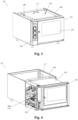
Figure 1 shows an axonometric construction drawing of the oven that is the invention subject, closed in the operating position and viewed from the right-hand side. -
Figure 2 shows an incomplete axonometric view of the oven as per the invention, schematically represented with the cooking module partially extracted for routine maintenance operations, and without the front panel in order to show the internal construction configuration. -
Figures 3 and 4 are axonometric views from the left-hand side of the aforementioned oven with reference, respectively, tofigure 1 and figure 2 . -
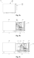
Figures 5a, 5b and 5c are orthogonal side projections of the oven in different positions, depending on the intended use; the oven is closed in its operating position infigure 5a . whilefigure 5b shows the cooking module partially extracted for routine maintenance, andfigure 5c shows said module totally extracted for special maintenance tasks. -
Figure 6 is a detailed side view of the functional equipment mounted on the side of the oven chamber in the partially extracted position, as at the precedingfigure 5b , where the body is schematically represented in lateral transparent mode in order to highlight the position. -
Figure 7a is an orthogonal projection from underneath the aforementioned oven; -
figures 7b and 7c are schematic lateral sectional views, according to the X - X sectional plane offigure 7a , with the module respectively closed and partially extracted for routine maintenance, highlighting the position of the carriages on the fixed tracks;figure 7d is an enlarged detail view of the carriage with the rear wheel engaged in the fixed track, as at the preceding figure. -
Figures 8a, 8b and 8c are axonometric representations of the oven as per the invention, which is beneficially integrated among the equipment of a community catering kitchen, in three alternative example configurations, being schematically represented with the cooking module partially extracted and without the door and/or front closing panel, in order to aid comprehension of the proposed solution. -
Figure 9 is an orthogonal projection of the front of an extractable oven with the body equipped with a tangential fan type anti-overheating safety device, according to this invention; -
Figure 10 is an orthogonal projection of a side wall of the aforementioned extractable oven as at the preceding figure; -
Figure 11 is an orthogonal projection of the same side wall of the aforementioned extractable oven as at the preceding figure, with the cooking module partially extracted in order to highlight the blank side wall; -
Figure 12 is an axonometric view of the aforementioned extractable oven, schematically represented with the body without the side wall corresponding to the blank side of the module, in the form of a structural frame, to highlight positioning of the anti-overheating safety device; -
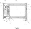
Figure 13a is a front sectional view of the aforementioned extractable oven, according to sectional plane Y-Y shown by the broken line inFig. 10 ; -
Figure 13b is an enlarged detail of the anti-overheating safety device, as at the area bounded by the shaded rectangle inFig. 13a . - Referring also to the contents of the drawings, as at the figures from 1 to 13b, this description concerns a cooking oven (10, 10a) for community catering, of the electric static or convection, steam, or combined type, or with other cooking modes, according to known technology, that is beneficially perfected in accessibility of internal functional equipment in order to facilitate technical maintenance tasks. This occurs thanks to a composite construction configuration that features two macro-elements: a fixed part composed of an outer body (100) functioning as an enclosure and support, and a mobile part comprising a cooking module (101) mounted inside the cabinet and at least partially extractable due to its ability to traverse horizontally on fixed tracks (114) located under the module (
Figs. 2 ,4 ,5b ,7c ,13a ). - The body (100) is a parallelepiped and provides protection and support for the cooking module (101) in the manner of a rigid, fixed and stable structural enclosure mounted on feet (111), being substantially void and including at least two fixed tracks (114) mounted on the internal base (112) to allow the module to traverse. The oven body can also function as a support base for a cook top or other equipment (118). Therefore, the body is entirely closed at the sides and on the upper surface in case of an isolated stand-alone or column configuration (
Fig. 8c ). Conversely, in case of a configuration integrated in a professional kitchen where the body is aligned in terms of height and depth, it offers a partially open upper face in order to allow installation of the equipment required on the kitchen worktop, such as a hob, electric hotplate, grill or fry-top (Figs. 1, 2 ,8a, 8b ) - The extractable cooking module (101) includes the oven chamber (102) and the technical equipment required for electric static or convection, or steam or combined cooking, and also to perform automatic washing, if fitted, of the oven chamber interior, and also incorporates the functional equipment (110) and the control and command means required for said cooking and said washing, in the form of a complete, compact, monobloc insert without a case, with multiple technical components exposed on one side (108, 110) and with the traversing means designed to engage with said fixed tracks (114 - 116) to allow the extraction movement (EP, ET) . For the purposes of the invention (101 - 103, 108 - 19, 114 - 117, EP, ET), other cooking modes such as gas type are deemed to be equivalent, fitting the related functional parts in said equipped side wall (108).
- Entering into the technical details for the purposes of the invention, the cooking module (101) has at least said functional parts (110) which are mounted on a side of the oven chamber (102) to form an equipped side wall (108), accommodated in an open space bounded by the body in the form of a housing (109), and easily accessible at the side with the module partially extracted (EP) for routine maintenance tasks. Conversely, the opposite side is blank (107) and adjacent to the body; consequently, the oven (10, 10a) has a narrower oven chamber (101) that is off-centre with respect to the body (100), having the equipped side wall (108, 109) located to the side, with the functional equipment (110, 110a - 110q) exposed. It is noted, therefore, that the vertical mid-line plane of the body is offset with respect to the vertical mid-line plan of the oven chamber, considered in an orthogonal direction with respect to the front, and also the weight of the module is not barycentric with respect to the body; positioning of the traversing means (114 - 116) under the module therefore takes account of this characteristic.
- The housing (108, 109) is closed at the front by a panel (104) that incorporates knobs and/or buttons and/or other command devices, connected to the electronic oven control systems, not shown in the figures, and which are of the centralised type in order to control the entire appliance in an integrated manner. These are preferably located inside the body being, for example, inclusive of a logic controller with specific programs, preloaded and settable by the user, with connection means for a remote control, if present, also operating via the Internet. In preference, said panel is held by a front bezel (105) which is fastened to the cooking module (101), being joined to the oven chamber around the door and protruding on the side in such a way as to accommodate the panel (104) and to be aligned around the perimeter with the outer edge of the body (100).
- The oven (10, 10a) has traversing means (114- 116) arranged orthogonally with respect to the front, in order to extract cooking module (101) from inside the body (100) towards the exterior i.e. to the front; said means are composed by at least two carriages on wheels (115, 116) mounted under the cooking module, facing downwards, which travel in engagement with and supported by the corresponding fixed tracks (114) mounted on the base of the body (112, 113) and facing upwards. To mount the fixed tracks in safe conditions, the base of the body is equipped with rigid support bars (113) positioned horizontally in correspondence with each track (
Figs. 7a, 7c ). Each carriage (115) includes preferably at least two wheels (116) which are respectively mounted at the front and rear ends of the carriage, in such a way as to balance the weight of the entire cooking module (101), in the inserted position and also during partial extraction (EP). A different number of wheels may be provided, mounted in other positions in relation to the dimensions and shape of the oven. The distribution of weight in the cooking module (101) is asymmetrical with respect to the mid line of the oven, the metal oven chamber (102) with glazed door being significantly heavier than the total weight of the aforementioned functional parts (110, 110a - 110q) which are externally mounted on the equipped side wall (108). Therefore, in order to achieve stable, balanced travel, said carriages and their corresponding fixed tracks are located under the oven chamber, in a barycentric position with respect to the entire module (101, 102, 108, 113), with one track adjoining and one lateral side of the body and the other one set back from the side (Fig. 7a ). - For technical routine and special maintenance operations, partial extraction (EP) is provided for said cooking module (101), limited at least to half of the total depth (P), preferably equal to three quarters of the depth, where a travel limit element (117) is fixed. To assure greater ease of use and for safety, this extraction limitation (EP) corresponds to an anti-tipping position of the cantilevered module, meaning the rear wheel (116) of the carriages (115) does not exit from its track (114) and the weight is borne by the front feet (
Figs. 7c, 7d ). The cooking module is totally extractable (ET) only for special maintenance, or removal, deactivating the travel limit element (117) (Fig. 5c ). This element (117) is rigid and can be deactivated, for example by tipping and/or rotation and/or insertion and/or flattening or an equivalent manoeuvre. In preference, the travel limit element is fastened to the upper side of the extractable cooking module (101), where it protrudes upwards such as to lodge against the upper edge of the body (Figs. 5a, 5b ,7b, 7c ); alternatively, it protrudes downwards in such a way as to be lodged against the lower edge, or with an equivalent extraction prevention solution. - Entering into greater detail of the multiple technical means, devices or components that are responsible for operation of the oven and are subject to frequent inspection and routine maintenance tasks, conventionally called functional equipment (110), it is noted that they are grouped together and exposed on said equipped side of the oven chamber (108) in the part closest to the front, in such a way as to extend progressively with the extraction movement and also such that they are all external in correspondence with said partial extraction (EP). To limit dimensions and facilitate routine maintenance tasks, the suction and/or expulsion means (110a) being integrated in the same equipped side wall (108) and incorporating at least one protruding element such as a hose, union or any type of long and/or large pipe, can be positioned at the rear with respect to the other parts and can be accessible, if necessary, by means of total extraction (ET) of the module (
Figs. 5a, 5b ,7b, 7c ). In the preferential but not limiting construction configuration (Fig. 6 ), merely by way of example and without limitation, the functional equipment (110a - 110q) of the equipped side wall (108) includes: - suction and/or expulsion means (110a);
- interior washing means (110b);
- a motor (110c);
- a circular heating element (110d);
- an upper heating element (110e);
- a working probe (110f);
- a safety probe (110g);
- solenoid valves (110h);
- a water pump (110i);
- contactors (1101);
- a lower heating element (110m);
- a timer (110n);
- and audible signalling device such as a beeper or buzzer (110o);
- a thermostat (110p);
- ventilation means (110q);
- any additional parts that are not shown can be mounted as additions or replacements, according to the required oven functions.
- Merely by way of a preferential example of the invention (10, 101, 108) without limitation, the following description concerns several construction configurations of the invention. A first variant of the electric-static oven is envisaged with mechanical thermostat control, and including at least two opposing opposite element type heat generators, respectively located on the top and on the bottom of the oven chamber, and means of manual control of the air inlet valve.
- Moreover, a second variant of the electric convection oven is envisaged with mechanical thermostat control, and including at least one lateral heating element with multi-speed ventilation means, a manual humidifier, manual air inlet valve management means, control means with mechanical relays and contactors.
- Furthermore, a third variant of a combined type oven is envisaged with electronic means to control temperature, ventilation, and humidity, and including at least one lateral heating element with multi-speed ventilation means, an upper static heating element with independent manual control, a possible lower static heating element with independent manual control, integrated automatic washing means, a manual and/or automatic humidifier, automatic means for management of the air inlet valve, multiple preloaded cooking programs, LED type interface means with a remote management application, control means with mechanical relays and contactors.
- Again by way of preferential example, a fourth variant of the combined oven is envisaged with multifunction electronic swipe or touch automatic control means, including at least one lateral heating element with multi-speed ventilation means, an upper static heating element with independent manual control, a possible lower static heating element with independent manual control, integrated automatic washing means, a humidification system with humidity percentage management, means for dry, steam, or combined cooking, multiple preloaded cooking programs with personalised management of recipes, control means with electronic power relays of the solid state or SSR type, fan speed control means with an inverter, having for example six speed levels.
- In all the envisaged variants, the oven (10) has an oven chamber (102) of standardised capacity, in compliance with European Gastronorm regulations, for example 4 GN 2/1 containers or 8 GN 1/1 containers, or also 4 GN1/1 containers. Also, the oven (10) can be installed under a standardised professional kitchen element, for example having a body (100) 800 mm wide and from 700 mm to 900 mm deep. The oven can therefore be beneficially integrated in commonly used community catering kitchen equipment. Merely by way of example, following is a description of three alternative integrated configurations (
Figs. 8a - 8c ) where the oven (10) is schematically represented with the module (101) partially extracted, to allow routine maintenance tasks, having the functional equipment mounted on an equipped side wall (108) of the oven chamber (102), all on the same side and easily accessible. In greater detail, the first figure (Fig. 8a ) shows the oven individually integrated between kitchen units and appliances of identical height and width, with the body functioning as a support base for a professional hob, a griddle or a grill (118). In the subsequent figures, the oven is shown in a multiple configuration, joined to and aligned with identical ovens, being respectively positioned side by side in a horizontal in-line array (Fig. 8b ) or stacked in a vertical wall-standing or column mounted array (Fig. 8c ). - An experimental analysis was carried out to ensure the technical maintenance tasks in the proposed cooking oven (10), construing this term in its widest sense and with any inspection and/or adjustment and/or repair and/or replacement task that can be performed in situ and rapidly, with extreme postural comfort and with the minimum effort. In particular, it is noted that the functional equipment (110, 110a - 110q) is all grouped together on the equipped side wall (108), visible and easily accessible from the same side once said module (101) is extracted, partially until locking of the travel limit element (117, EP), or completely, without travel limit (ET). This therefore removes the need to extract, rotate, and dismantle the appliance to reach the required device time by time, and also removes the need to transport the oven to an equipped workshop, unlike the case in conventional ovens to replace parts integrated internally in an inconvenient or inaccessible position.
- In addition, it was noted that the proposed oven solution (10, 108) significantly facilitates routine maintenance technical tasks, and also reduces inconvenience in the kitchen due to the shorter maintenance times and limited space to carry out the tasks. In practice, allowing direct side access to the main functional equipment (110a - 110q), grouped together on the equipped side wall (108) of the chamber, in order to perform said tasks the minimum space for partial extraction (EP) is sufficient corresponding to approximately the generally unoccupied space in front of any worktop or professional appliance (
Figs. 8a, 8b, 8c ). - Furthermore, for the purposes of this description, the term control and command means, in all their forms, is generally construed as cooperation of digital and/or electrical and/or mechanical components, directly or indirectly one with respect to and/or reciprocally with the other. Said cooperation can be achieved with digital and/or electrical and/or mechanical components and any additional intermediate elements, being formed entirely as a single unit, joined one to the other. Likewise, the term control equipment is construed with a broad meaning, as cooperation of various components and/or devices and/or additional intermediate elements. It is also important to note that the construction and layout of the elements of the invention as shown in the construction form is purely an example.
- Even though only certain preferential construction forms of the proposed innovation have been described in detail in this description, industry experts who are informed of this disclosure will easily appreciate that many modifications are possible, such as for example variations in dimensions, structures, shapes and proportions of the various elements, parameter values, assembly layouts, use of materials, and other, without materially departing from the new instructions and equivalent benefits of the cited object. For example, elements shown as being formed in one piece can be constructed in several parts or elements shown as several parts can be formed as a single piece, operation of the interfaces can be inverted or anyway altered, the length or width of the structures and/or parts or connectors or other system elements can be varied, the nature or number of control positions provided among the elements can be varied. Note that the elements and/or groups of the proposed system can be constructed of any of a wide variety of materials that provide sufficient strength or durability, in any of a wide variety of combinations. Consequently, all these alterations are to be construed as included within the framework of this invention. Other replacements, modifications, changes and omissions can be made to the design, to the operating conditions, to the list of requirements and other example forms of construction, without thereby departing from the spirit of this invention.
- Finally, it must be understood that some construction configurations of the invention described herein can be potentially combined with the other described configurations to form configurations that are equivalent or included within the context of this description. All example configurations provided for in this description are for illustration purposes and cannot be interpreted as limitations.
- In particular, a construction configuration of the extractable or partially extractable oven (10a), constructed as described above and having the body (100) equipped with a beneficial anti-overheating safety device (120) (
Figs. 9 - 13b ) is intended as included in the scope of this description. Overall, this revised variant of the oven has said cooking module (101) mounted on carriages and fixed tracks (114, 115) fastened to the base of the body, which allow horizontal travel of the module; the cooking module (101) is equipped with a door (103) for front access to the oven chamber (102), having on the exterior the user interface means (104) and has an equipped side wall (108) where the functional parts (110) for food cooking activities (Figs. 12 ,13a ) are grouped together. In greater technical detail, the functional parts (110) are mounted on just one side wall of the oven chamber (102) to form an equipped side wall (108), accommodated in an open space bounded by the body (100) in the form of a housing (109). In this manner, the parts thus grouped together on the same equipped side wall are all easily accessibly with the module partially extracted (101, 108, EP), in order to perform routine maintenance tasks quickly, also when the oven is adjacent to a kitchen unit or an orthogonal wall (Figs. 11, 12 ). - The side wall (107) opposite to said equipped side wall (108) is therefore free of devices or functional parts, being closed and plain in the form of a blank side panel that is adjacent to a corresponding side of the body (129). Consequently, the oven (10a) has the oven chamber (102) narrower than and offset with respect to the body (100), having on one side the equipped side wall (108) with the functional equipment (110) exposed. It is noted, therefore, that the vertical mid-line plane of the body is offset with respect to the vertical mid-line plan of the oven chamber, considered in an orthogonal direction with respect to the front, and also the weight of the extractable module (103) is not barycentric with respect to the body; positioning of the traversing means or carriages (113, 114, 115) under the module therefore takes this characteristic into account.
- Conventionally, the definition of blank side wall of the body (129) refers to a side wall of the body (100) that is closed and without functional parts; by extension, a configuration of a blank side wall wherein, in place of or in combination with said closed side of the body there is an adjacent kitchen unit, or an adjacent wall, with an identical closing effect is construed as included and equivalent in the context of this description. Essentially, for the purposes of the invention the proposed solution principally solves the aforementioned problem of overheating of the body in correspondence with the blank side wall (107) of the module (102, 103) adjoining said blank side wall (129) of the body (100) construed as described above, without incorporating any dedicated device inside it and without obstructing extraction of the module, thus solving the mentioned safety problems in the oven and/or by extension in the adjacent kitchen units and/or in walls adjacent to its side (
Figs. 10 ,11, 12 ). - For the purposes of the invention (
Figs. 12 ,13a ), the extractable module has said blank side wall (107), opposite the equipped side wall (108), which is adjacent to the body and is therefore positioned in parallel to and adjacent to said blank side wall of the body (129) leaving between the two side walls (107, 129) a cavity (127) of limited width, less than 20 mm, that allows free travel while limiting the use of space. Said cavity (127) is open to the exterior at the bottom, having a downward facing opening shaped like a long and narrow lower slit (128) delimited externally by the side of the body. In particular, the invention provides that the body be also equipped with a beneficial anti-overheating safety device (120) that acts directly from the exterior, supplying an air flow into said cavity (110), through said lower slit (128), in a vertical upward direction, in such a way as to create a laminar convection circulation between body and oven chamber (100, 102). In this manner, excess heat is expelled from the cavity, anyway allowing total or partial (EP) extraction of the cooking module (101), without interfering with the movement. An anti-overheating system is therefore proposed for extractable ovens implemented with an independent ventilation device, with a specifically shaped case that functions as the structure and fan shroud, being fastened externally to the body, under the cooking module, in the manner of a safety accessory independent from the cooking equipment of the oven. Essentially, the fan is not part of the oven's functional cooking components but must be viewed as a safety component of the body; likewise it is not built internally into the oven but integrated externally to it (Figs. 11, 12 ,13a ). - For a description (
Fig. 13a ,13b ) of the proposed solution with greater construction detail, said safety device is a tangential fan (120) mounted horizontally under the cooking module (101), in correspondence with the lower slit (128) of the cavity (107, 127, 129), where it is fastened to the body (100) between two lateral feet (111) or between equivalent elements of said body and cooking module to raise it from the floor surface. The fan rotor (121) therefore extends in a longitudinal direction, with axis of rotation (122) parallel to said slit and with an air outlet (126) facing upwards in the precise position of said slit (128) in order to deliver a vertical air flow (125) directly, in an upward direction. The tangential fan (120) is therefore external with respect to the cooking module and body, disregarding the feet (111). Said fan (120) is equipped with a shaped casing (123) functioning as an enclosure, support, and directing the air flow, equipped internally with the rotor (121) that produces the air flow (125), a motor that drives the rotor, transmission means to connect motor to rotor, and integrated vents for air intake (124) and expulsion, having said air outlet (126) as the upper terminal, said vents channelling the air flow (125) drawn into the fan and forcing it into the cavity (127, 128), thus creating convective air circulation that promotes movement and/or expulsion of the hot air. - The fan (120) is controlled by at least one safety thermostat (130) that regulates its automatic activation based on the temperature reading; alternatively or in combination with the use of thermostats, known technological solutions can be utilised to program cyclic or remote activations. For example, the invention can be appropriately served by a pad or Klixon sensor that measures the temperature of a surface internal to the body, or a cavity air temperature sensor. Said thermostat (130), preferably but not exclusively, manages all integrated cooling fans of the oven (10a), both in correspondence with the equipped side wall (108, 109) and the blank side wall (107, 120). In this case, it (130) can be beneficially installed in the housing (109) opposite the blank side wall (
Fig. 13a ); this system ensures that both the body (100) and the functional equipment (110) are constantly kept at a suitable temperature, preventing overheating. The thermostat can anyway be incorporated in a different convenient position, such as in the cavity of the blank side wall (107, 127, 129), activating specifically the fan (120) of the proposed device. In general, said fan plus the thermostat (120, 130) make it possible to maintain the temperature of the oven within legislative limits during its use. - The construction configuration described above is an example of the invention, wherein all said characteristics are to be construed as included within the framework of this innovation. Other replacements, alterations, changes and omissions can be made to the described solution, the operating conditions, the list of requirements and other example forms of construction, without thereby departing from the matters described or suggested in relation to this invention, including equivalent solutions.
- Finally, it shall be understood that any solutions designed overall to form equivalent configurations are included within the framework of this description.
-
- (10) cooking oven with cooking module partially extractable on fixed tracks, according to this invention;
- (10a) variant of the aforementioned oven, with body having an anti-overheating safety device, according to this invention;
- (100) fixed and load bearing outer body;
- (101) extractable cooking module;
- (102) oven chamber;
- (103) door;
- (104) front closing panel, extended laterally to close the technical void and as a mounting panel for user interface means for oven controls and/or monitoring devices;
- (105) front bezel supporting the panel;
- (106) cooking module base;
- (107) oven chamber blank side wall;
- (108) oven chamber equipped side wall, accommodated in the housing contained by the body;
- (109) equipped side wall housing;
- (110) functional equipment, technical means broadly construed as devices and components used for specific oven functions and subject to maintenance being, in a preferential and non-limiting example: (110a) suction and/or expulsion means, (110b) interior washing means, (110c) motor, (110d) circular heating element, (110e) upper heating element, (110f) working probe, (110g) safety probe, (110h) solenoid valves, (110i) water pump, (1101) contactors, (110m) lower heating element, (110n) timer, (110o) beeper or buzzer type audible warning system, (110p) thermostat, (110q) ventilation means, with all and any additional parts according to the functions time by time provided by the oven;
- (111) feet, floor spacing elements of body and cooking module;
- (112) body base;
- (113) structurally rigid support element for a fixed track, implemented to reinforce the oven body base;
- (114) fixed track, joined to the body and facing upwards;
- (115) carriages, joined to the cooking module;
- (116) carriage wheel;
- (117) travel limit element;
- (118) worktop and/or professional cooktop;
- (120) tangential fan type anti-overheating safety device;
- (121) fan rotor;
- (122) fan axis of rotation, horizontal and parallel to the slit;
- (123) fan casing;
- (124) fan air intake duct;
- (125) air flow generated by fan;
- (126) fan outlet vent;
- (127) cavity, between extractable module blank side and body;
- (128) lower slit, cavity opening facing downwards;
- (129) body blank side;
- (130) thermostat;
- (EP) partial extraction, for routine maintenance;
- (ET) total extraction, for special maintenance and removal.
- (P) total depth.
Claims (17)
- A cooking oven (10, 10a) for community catering, of the type extractable on guides, incorporating: a body, an oven chamber and the related technical systems to carry out, at least, cooking in electric static or convection or steam or combined mode or in other modes, with operating equipment and control and command means; said cooking oven (10, 10a), characterised by the fact that it is composed of a fixed part constituting said body (100) which functions as an enclosure and support, and a mobile part composed of a cooking module (101) mounted inside the body and extractable from it by means of a horizontal travel movement, on fixed tracks (114) located below it; said cooking module (101) incorporating said oven chamber (102), said functional equipment (110) and said control and monitoring means, where at least said functional equipment (110) is grouped together and mounted on the same side of said oven chamber in such a way as to constitute an equipped side wall (108) of the oven chamber (102); said equipped side wall (108), accommodated in an open housing (109) contained by the body, with the functional parts (110) being accessible from the side for maintenance when said cooking module (101) is extracted at least partially (EP); and where the travel movement of said cooking module (101) takes place by means of at least two carriages on wheels (115, 116) affixed to the base (106) of the module and facing downwards, said wheels being engaged in corresponding fixed tracks (114) affixed to the base of said body (100, 112, 113) and facing upwards; and wherein said tracks and said carriages (114, 115) are reciprocally parallel and orthogonal with respect to the front of the oven, located under the oven chamber in a barycentric position with respect to the module (101, 102, 108, 113); and wherein said horizontal travel movement is locked by a travel limit element (117) that restricts the movement to partial extraction (EP) of the module (101), equal to at least half the total depth (P), in such a way as to allow the functional equipment (108, 110) to exit from the body and also such that at least one wheel of each carriage (115, 116) is supported by the respective track (114).
- A cooking oven (10, 10a), according to claim 1, characterised by the fact that said equipped side wall (108, 110) is the left-hand side of the oven chamber, when observed from the front.
- A cooking oven (10, 10a), according to claim 1 or 2, characterised by the fact that it functions as a base for a worktop and/or professional cooktop (118), mounted on top of the body (100).
- A cooking oven (10, 10a), according to claim 1 or 2 or 3, characterised by the fact that it is in an isolated or stand-along configuration, with said body (100) being closed.
- A cooking oven (10), according to claim 3 or 4, characterised by the fact that it has standardised dimensions of 800 mm in width and depth of between 700 mm and 900 mm.
- A cooking oven (10), according to the preceding claim, characterised by the fact that it can be combined in a multiple configuration, where it is side by side with and aligned with other cooking ovens (10) in an in-line horizontal array, and/or in a vertical column array, and/or combined together in the manner otherwise referred to as a matrix type array.
- A cooking oven (10), according to any of the preceding claims, characterised by the fact that said travel limit element (117) allows extraction of the cooking module (101, EP) by 3/4 of the total depth (P), considering a 10% tolerance; and wherein said travel limit element (117) is a rigid element fastened to the cooking module (101), and protruding upwards or downwards in such a way as to locate, respectively, against the upper or lower edge of the body.
- A cooking oven (10), according to any of the preceding claims, characterised by the fact that said travel limit element (117) can be deactivated to allow total extraction (ET) of the cooking module (101).
- A cooking oven (10), according to any of the preceding claims, characterised by the fact that said equipped side wall (108) includes the following functional parts (110, 110a - 110q): suction and/or expulsion means (110a), interior washing means (110b), a motor (110c), a circular heating element (110d), an upper heating element (110e), a working probe (110f), a safety probe (110g), solenoid valves (110h), a water pump (110i), contactors (1101), a lower heating element (110m), a timer (110n), an audible warning system of the beeper or buzzer type (110o), a thermostat (110p), ventilation means (110q), and/or possible additional parts according to the intended functions of the oven.
- A cooking oven (10), according to the preceding claim, characterised by the fact that said suction and/or expulsion means (110a) are located at the rear with respect to the other functional equipment (110, 110b - 110q) positioned in proximity to the front, and including at least one protruding element and/or a pipe that exits completely from the body only when the module is completely extracted (ET).
- A cooking oven (10), according to any of the preceding claims, characterised by the fact that said baking module (101) incorporates a manual and/or automatic oven chamber washing system the oven chamber (102), which features radiused and washable interior surfaces, being without live edges and being of watertight construction.
- A cooking oven (10), according to any of the claims from 1 to 8, characterised by the fact that it is of the electrical - static type with mechanical thermostat control, and including at least: two opposing electrical heating element type heat generators, respectively positioned on the upper and lower part of the oven chamber, and manual means for management of the air inlet valve.
- A cooking oven (10), according to any of the claims from 1 to 8, characterised by the fact that it is of the electrical - static type with mechanical thermostat control, and including at least: one lateral heating element with multi-speed ventilation means, a manual humidifier, means for manual management of the air inlet valve, control means with mechanical relays and contactors.
- A cooking oven (10), according to any of the claims from 1 to 8, characterised by the fact that it is of the combined type with electronic means to control temperature, ventilation, and humidify, and including at least: one lateral heating element with multi-speed ventilation means, an upper static heating element with manual independent control, integrated means for automatic washing, a manual and/or automatic humidifier, means for automatic management of the air inlet valve, multiple preloaded cooking programs, interface means of the LED type with a remote management application, control means with mechanical relays and contactors.
- A cooking oven (10), according to any of the claims from 1 to 8, characterised by the fact that it is of the combined type with multifunction automatic electronic control means of the swipe and/or touch type, including at least: one lateral heating element with multi-speed ventilation means, an upper static heating element with independent manual control, a possible lower static heating element with independent manual control, integrated means for automatic washing, a humidification system with percentage type humidity management, means produce dry, steam, or combined cooking modes, multiple preloaded cooking programs with personalised recipe management, control means with electronic power relays of the solid state or SSR type, fan speed control means with an inverter, having for example six speed levels.
- A cooking oven (10a), according to claim 1 or 2 or 3 or 4, characterised by the fact that it features means to raise said body (100) and said cooking module (101) above the floor, and wherein said cooking module (101) has its side wall facing said equipped side wall (108) being a blank side (107) adjacent to and parallel to a corresponding blank side wall of the body (129), creating between them a cavity (127) of width less than 20 mm with at least one lower slit (128) open below the module (101); and wherein the body (100) is equipped with an anti-overheating safety device composed of a tangential fan (120) fastened to it (100), under the cooking module (101), said tangential fan (120) being aligned with the cavity (127) with the axis of rotation of its rotor (121, 122) being horizontal and parallel to said lower slit (128); said tangential fan (120) having a casing (123) that includes an air outlet vent (126) facing upward in correspondence with said lower slit (128), in order to supply its air flow (125) directly in a vertical and upward direction.
- A cooking oven (10a), according to the preceding claim, characterised by the fact that said housing (109) is equipped with at least one safety thermostat (130) to activate at least said tangential fan (120).
Applications Claiming Priority (2)
| Application Number | Priority Date | Filing Date | Title |
|---|---|---|---|
| IT202023000004203U IT202300004203U1 (en) | 2023-10-12 | 2023-10-12 | OVEN WITH PARTIALLY EXTRACTABLE COOKING MODULE ON FIXED RAILS |
| IT202400004077 | 2024-10-09 |
Publications (1)
| Publication Number | Publication Date |
|---|---|
| EP4538600A1 true EP4538600A1 (en) | 2025-04-16 |
Family
ID=93335306
Family Applications (1)
| Application Number | Title | Priority Date | Filing Date |
|---|---|---|---|
| EP24020308.3A Pending EP4538600A1 (en) | 2023-10-12 | 2024-10-10 | Oven with partially extractable cooking module on fixed tracks |
Country Status (1)
| Country | Link |
|---|---|
| EP (1) | EP4538600A1 (en) |
Citations (5)
| Publication number | Priority date | Publication date | Assignee | Title |
|---|---|---|---|---|
| DE1247592B (en) * | 1959-03-23 | 1967-08-17 | Siemens Electrogeraete Ges Mit | Built-in stove |
| JPS5634205U (en) * | 1979-08-23 | 1981-04-03 | ||
| JPS6016240A (en) * | 1984-06-07 | 1985-01-28 | Matsushita Electric Ind Co Ltd | heating cooker |
| US7287462B2 (en) | 2000-12-01 | 2007-10-30 | Bsh Bosch Und Siemens Hausgeraete Gmbh | High-level built-in oven unit |
| WO2010125010A1 (en) | 2009-04-28 | 2010-11-04 | Meneghetti - S.P.A. Unipersonale - | Vertically movable built-in oven |
-
2024
- 2024-10-10 EP EP24020308.3A patent/EP4538600A1/en active Pending
Patent Citations (5)
| Publication number | Priority date | Publication date | Assignee | Title |
|---|---|---|---|---|
| DE1247592B (en) * | 1959-03-23 | 1967-08-17 | Siemens Electrogeraete Ges Mit | Built-in stove |
| JPS5634205U (en) * | 1979-08-23 | 1981-04-03 | ||
| JPS6016240A (en) * | 1984-06-07 | 1985-01-28 | Matsushita Electric Ind Co Ltd | heating cooker |
| US7287462B2 (en) | 2000-12-01 | 2007-10-30 | Bsh Bosch Und Siemens Hausgeraete Gmbh | High-level built-in oven unit |
| WO2010125010A1 (en) | 2009-04-28 | 2010-11-04 | Meneghetti - S.P.A. Unipersonale - | Vertically movable built-in oven |
Similar Documents
| Publication | Publication Date | Title |
|---|---|---|
| CA2365023C (en) | Food grilling system for oven cavity with byproduct removal | |
| US9513016B2 (en) | Bottom-loading cooking appliance | |
| CN109416186B (en) | Insert for downdraft range hood | |
| KR102824831B1 (en) | Hob system | |
| KR101520499B1 (en) | Oven range | |
| KR20140030020A (en) | Smokeless grill | |
| JP5702815B2 (en) | Cooker | |
| JPWO2017145792A1 (en) | Induction heating cooker | |
| EP4538600A1 (en) | Oven with partially extractable cooking module on fixed tracks | |
| EP4528111A2 (en) | Cooking hob with extractor hood | |
| KR100866501B1 (en) | Exhaust structure of hood with internal cooking space | |
| RU93502U1 (en) | ELECTRIC STOVE WITH A FRY CUPBOARD (OPTIONS) | |
| KR20210008811A (en) | Closed Type Smokeless Automatic Fryer | |
| CN222278669U (en) | Multipurpose integrated kitchen | |
| US20180283699A1 (en) | Oven range appliance having a ventilation system | |
| US11988392B2 (en) | Removable heating element cover for an oven appliance and methods of detecting same | |
| JP2016169940A (en) | Cooker | |
| KR200312289Y1 (en) | Frying apparatus attached on a table | |
| KR102424073B1 (en) | Induction cooker for pettitoes | |
| IT202300004203U1 (en) | OVEN WITH PARTIALLY EXTRACTABLE COOKING MODULE ON FIXED RAILS | |
| KR101801326B1 (en) | Induction oven range ventilation system | |
| GB2349457A (en) | Cooking appliance | |
| EP4595840A1 (en) | Air fryer with air suction on side portion | |
| JP6270886B2 (en) | Cooker | |
| EP4365494A1 (en) | Kitchen extractor hood and cooking system |
Legal Events
| Date | Code | Title | Description |
|---|---|---|---|
| PUAI | Public reference made under article 153(3) epc to a published international application that has entered the european phase |
Free format text: ORIGINAL CODE: 0009012 |
|
| STAA | Information on the status of an ep patent application or granted ep patent |
Free format text: STATUS: THE APPLICATION HAS BEEN PUBLISHED |
|
| AK | Designated contracting states |
Kind code of ref document: A1 Designated state(s): AL AT BE BG CH CY CZ DE DK EE ES FI FR GB GR HR HU IE IS IT LI LT LU LV MC ME MK MT NL NO PL PT RO RS SE SI SK SM TR |
|
| RIN1 | Information on inventor provided before grant (corrected) |
Inventor name: MINELLA, ANDREA Inventor name: TEGNER, MARCO Inventor name: BRISTOT, DANIELE Inventor name: ZOCCOLAN, ADAMO Inventor name: D'AMBROGIO, MARCO |
|
| P01 | Opt-out of the competence of the unified patent court (upc) registered |
Free format text: CASE NUMBER: APP_29275/2025 Effective date: 20250619 |
|
| STAA | Information on the status of an ep patent application or granted ep patent |
Free format text: STATUS: REQUEST FOR EXAMINATION WAS MADE |
|
| 17P | Request for examination filed |
Effective date: 20250729 |
|
| RIN1 | Information on inventor provided before grant (corrected) |
Inventor name: D'AMBROGIO, MARCO Inventor name: ZOCCOLAN, ADAMO Inventor name: BRISTOT, DANIELE Inventor name: TEGNER, MARCO Inventor name: MINELLA, ANDREA |