EP4538538A1 - Centrifugal cooling fan for a domestic appliance and domestic appliance having a centrifugal cooling fan - Google Patents
Centrifugal cooling fan for a domestic appliance and domestic appliance having a centrifugal cooling fan Download PDFInfo
- Publication number
- EP4538538A1 EP4538538A1 EP23202513.0A EP23202513A EP4538538A1 EP 4538538 A1 EP4538538 A1 EP 4538538A1 EP 23202513 A EP23202513 A EP 23202513A EP 4538538 A1 EP4538538 A1 EP 4538538A1
- Authority
- EP
- European Patent Office
- Prior art keywords
- blades
- cooling fan
- blade
- centrifugal cooling
- domestic appliance
- Prior art date
- Legal status (The legal status is an assumption and is not a legal conclusion. Google has not performed a legal analysis and makes no representation as to the accuracy of the status listed.)
- Pending
Links
Images


Classifications
-
- F—MECHANICAL ENGINEERING; LIGHTING; HEATING; WEAPONS; BLASTING
- F04—POSITIVE - DISPLACEMENT MACHINES FOR LIQUIDS; PUMPS FOR LIQUIDS OR ELASTIC FLUIDS
- F04D—NON-POSITIVE-DISPLACEMENT PUMPS
- F04D29/00—Details, component parts, or accessories
- F04D29/26—Rotors specially for elastic fluids
- F04D29/28—Rotors specially for elastic fluids for centrifugal or helico-centrifugal pumps for radial-flow or helico-centrifugal pumps
- F04D29/281—Rotors specially for elastic fluids for centrifugal or helico-centrifugal pumps for radial-flow or helico-centrifugal pumps for fans or blowers
-
- F—MECHANICAL ENGINEERING; LIGHTING; HEATING; WEAPONS; BLASTING
- F04—POSITIVE - DISPLACEMENT MACHINES FOR LIQUIDS; PUMPS FOR LIQUIDS OR ELASTIC FLUIDS
- F04D—NON-POSITIVE-DISPLACEMENT PUMPS
- F04D29/00—Details, component parts, or accessories
- F04D29/26—Rotors specially for elastic fluids
- F04D29/28—Rotors specially for elastic fluids for centrifugal or helico-centrifugal pumps for radial-flow or helico-centrifugal pumps
- F04D29/30—Vanes
-
- F—MECHANICAL ENGINEERING; LIGHTING; HEATING; WEAPONS; BLASTING
- F04—POSITIVE - DISPLACEMENT MACHINES FOR LIQUIDS; PUMPS FOR LIQUIDS OR ELASTIC FLUIDS
- F04D—NON-POSITIVE-DISPLACEMENT PUMPS
- F04D29/00—Details, component parts, or accessories
- F04D29/66—Combating cavitation, whirls, noise, vibration or the like; Balancing
- F04D29/661—Combating cavitation, whirls, noise, vibration or the like; Balancing especially adapted for elastic fluid pumps
- F04D29/666—Combating cavitation, whirls, noise, vibration or the like; Balancing especially adapted for elastic fluid pumps by means of rotor construction or layout, e.g. unequal distribution of blades or vanes
-
- F—MECHANICAL ENGINEERING; LIGHTING; HEATING; WEAPONS; BLASTING
- F05—INDEXING SCHEMES RELATING TO ENGINES OR PUMPS IN VARIOUS SUBCLASSES OF CLASSES F01-F04
- F05D—INDEXING SCHEME FOR ASPECTS RELATING TO NON-POSITIVE-DISPLACEMENT MACHINES OR ENGINES, GAS-TURBINES OR JET-PROPULSION PLANTS
- F05D2240/00—Components
- F05D2240/20—Rotors
- F05D2240/30—Characteristics of rotor blades, i.e. of any element transforming dynamic fluid energy to or from rotational energy and being attached to a rotor
- F05D2240/303—Characteristics of rotor blades, i.e. of any element transforming dynamic fluid energy to or from rotational energy and being attached to a rotor related to the leading edge of a rotor blade
-
- F—MECHANICAL ENGINEERING; LIGHTING; HEATING; WEAPONS; BLASTING
- F05—INDEXING SCHEMES RELATING TO ENGINES OR PUMPS IN VARIOUS SUBCLASSES OF CLASSES F01-F04
- F05D—INDEXING SCHEME FOR ASPECTS RELATING TO NON-POSITIVE-DISPLACEMENT MACHINES OR ENGINES, GAS-TURBINES OR JET-PROPULSION PLANTS
- F05D2240/00—Components
- F05D2240/20—Rotors
- F05D2240/30—Characteristics of rotor blades, i.e. of any element transforming dynamic fluid energy to or from rotational energy and being attached to a rotor
- F05D2240/304—Characteristics of rotor blades, i.e. of any element transforming dynamic fluid energy to or from rotational energy and being attached to a rotor related to the trailing edge of a rotor blade
-
- F—MECHANICAL ENGINEERING; LIGHTING; HEATING; WEAPONS; BLASTING
- F05—INDEXING SCHEMES RELATING TO ENGINES OR PUMPS IN VARIOUS SUBCLASSES OF CLASSES F01-F04
- F05D—INDEXING SCHEME FOR ASPECTS RELATING TO NON-POSITIVE-DISPLACEMENT MACHINES OR ENGINES, GAS-TURBINES OR JET-PROPULSION PLANTS
- F05D2250/00—Geometry
- F05D2250/60—Structure; Surface texture
- F05D2250/61—Structure; Surface texture corrugated
-
- F—MECHANICAL ENGINEERING; LIGHTING; HEATING; WEAPONS; BLASTING
- F05—INDEXING SCHEMES RELATING TO ENGINES OR PUMPS IN VARIOUS SUBCLASSES OF CLASSES F01-F04
- F05D—INDEXING SCHEME FOR ASPECTS RELATING TO NON-POSITIVE-DISPLACEMENT MACHINES OR ENGINES, GAS-TURBINES OR JET-PROPULSION PLANTS
- F05D2250/00—Geometry
- F05D2250/70—Shape
Definitions
- the present invention relates to a domestic appliance, in particular a domestic oven, for the treatment of food products, preferentially for the thermal treatment of food products.
- the present invention also relates to a domestic appliance, preferentially a domestic oven, having at least one centrifugal cooling fan.
- domestic appliances such as domestic ovens
- Such domestic appliances are known to comprise a main body having a treatment cavity within which food products are retained during their treatment, a main opening for accessing the treatment cavity, a door for selectively closing and opening the main opening, an electronic compartment arranged above the treatment cavity and containing electronic components and a cooling fan, e.g. a centrifugal cooling fan, configured to generate a cooling stream for cooling the electronic components.
- a cooling fan e.g. a centrifugal cooling fan
- cooling fan is configured to generate a gas stream toward and through an outlet opening.
- centrifugal cooling fan for a domestic appliance according to the independent claim 1.
- a centrifugal cooling fan for a domestic appliance comprising at least an impeller.
- the impeller comprises a separation plate having a first face and a second face opposed to the first face, a plurality of first blades axially extending from the first face of the separation plate and a plurality of second blades axially extending from the second face of the separation plate.
- Each first blade and each second blade comprise a trailing edge and a leading edge and each trailing edge and/or each leading edge comprises a serrated section.
- the plurality of first blades is misaligned with respect to the plurality of second blades.
- the Applicant has observed that the combination of the serrated sections and the misalignment allows to efficiently reduce the noise, which is generated during operation of the centrifugal cooling fan.
- the impeller results in a uniform low-pressure distribution on the first blades and the second blades.
- the asynchronous configuration helps to alternate and reduce pressure spots.
- first blades and the second blades allow to have higher flow velocities near the trailing edges of the blades, which again allows to better distribute the pressure.
- the impeller provides nearly the same flow rate with lower rpm and lower blade passing frequency compared to the state-of-the-art solutions, resulting in a lower sound power and lower tonality.
- each first blade may be interposed between two respective second blades and each second blade may be interposed between two respective first blades.
- the impeller may be configured to rotate about a rotation axis.
- the first blades of the plurality of first blades may be equally spaced about the rotation axis of the impeller.
- the second blades of the plurality of second blades may be equally spaced about the rotation axis.
- each first blade may be angularly displaced from the respective trailing edges of the second blades and the respective trailing edge of each second blade may be angularly displaced from the respective trailing edges of the first blades.
- each first blade may be arranged at a respective first angular position and the respective trailing edge of each second blade may be arranged at a respective second angular position with respect to the rotation axis.
- the respective second angular positions are angularly displaced from the respective first angular positions.
- each first blade and each second blade may comprise a respective first end portion in contact with the separation plate and a respective free end portion opposite to the first end portion.
- the first blades and the second blades radially protrude away from the separation plate.
- the plurality of trailing edges of the first blades may define a first circle of a first diameter and the plurality of trailing edges of the second blades may define a second circle of a second diameter.
- An outer diameter of the separation plate may be smaller than the first diameter and the second diameter.
- the first diameter and the second diameter may equal one another.
- the outer diameter of the separation plate is smaller than the first diameter and the second diameter by at least a factor of 0,9, preferentially by at least a factor of 0,8.
- the respective height of each first blade and of each second blade increases towards the trailing edge and/or decreases towards the center of the separation plate.
- the centrifugal cooling fan may comprise a fan housing having a seat and the impeller may be arranged within the seat.
- the impeller is formed as a single piece, preferentially a single piece formed from a polymer, more preferentially a single piece formed during a polymer molting process.
- each serrated section may present a sinusoidal shape. In this way, one optimizes the performance of the impeller by keeping low noise levels.
- a domestic appliance preferentially a domestic oven, for the thermal treatment of food products comprising the centrifugal cooling fan.
- the domestic appliance may further comprise one or more electrical components arranged within an electronic compartment of the domestic appliance.
- the centrifugal cooling fan may be configured to generate a cooling air stream for cooling the one or more electrical components and to direct the air out of an outlet opening of the domestic appliance.
- the domestic appliance may further comprise a treatment cavity for retaining the food product and having an opening for introducing and/or removing the food product.
- the domestic appliance further comprises a door for selectively closing and opening the aperture; wherein the door comprises a flow path and the centrifugal cooling fan is configured to create an air flow through the flow path; and/or wherein the treatment cavity comprises at least one evacuation hole and the centrifugal cooling fan is configured to evacuate fluids from the treatment cavity and to direct the fluids out of an outlet opening of the domestic appliance.
- number 1 indicates as a whole a domestic appliance, preferentially a domestic oven, for the treatment, preferentially the thermal treatment, of food products.
- domestic appliance 1 may comprise at least:
- main body 2 may comprise an electronic compartment 5 within which electronic components of domestic appliance 1 are housed in.
- domestic appliance 1 may comprise one or more of: a microwave unit configured to treat the food product by means of microwaves and to introduce microwaves into treatment cavity 3, a heat convection unit configured to create a flow of heat within treatment cavity 3 and a steam generation unit configured to introduce steam into treatment cavity 3.
- the microwave unit may be arranged within electronic compartment 5.
- one or more of the electronic components may be comprises by one or more of the microwave unit, the heat convection unit and the steam generation unit.
- Domestic appliance 1 may comprise a control unit configured to control operation of domestic appliance 1 and being at least partially arranged within electronic compartment 5.
- domestic appliance 1 comprises a centrifugal cooling fan 6 configured to at least generate a cooling air flow within electronic compartment 5, and preferentially to also evacuate fluids (e.g. steam, air, and so on) from treatment cavity 3.
- centrifugal cooling fan 6 may be at least partially arranged within electronic compartment 3 and/or may be on fluidic connecting with treatment cavity 3.
- main body 2 may comprise an evacuation hole and centrifugal cooling fan 6 being in fluidic connection with treatment cavity 3 through the evacuation hole.
- centrifugal cooling fan 6 may be configured to evacuate fluids from treatment chamber 3 through the evacuation hole.
- main body 2 may comprise one or more inlet holes configured to establish a fluidic connection between an outside space and electronic compartment 3.
- centrifugal cooling fan 6 may be configured to generate a flow of cooling air from the outside space into electronic compartment 3 through the one or more inlet holes.
- centrifugal cooling fan 6 may also be configured to generate a flow of fluids through an outlet opening 7 out of domestic appliance 1, preferentially main body 2.
- outlet opening 7 may be arranged above (see Figure 1 ) or, alternatively, below (not shown) door 4.
- outlet opening 7 may have an elongated configuration.
- door 4 may comprise a flow channel and centrifugal cooling fan 6 may also be configured to generate a flow of air from the outside space into and within the flow channel.
- domestic appliance 1 may comprise a flow conduit 8 being in fluidic connection with the flow channel and centrifugal cooling fan 6.
- centrifugal cooling fan 6 may be configured to generate the flow of air within the flow channel and into and through the flow conduit.
- centrifugal cooling fan 6 may comprise at least two inlets configured to draw fluids from different directions (e.g. from below and above).
- centrifugal cooling fan 6 comprises an impeller 15 configured to generate the respective drawing forces for generating (desired) fluid flows, preferentially through the respective two inlets.
- impeller 15 may be realized as a single piece, e.g. formed by molding.
- centrifugal cooling fan 6 may also comprise a fan housing 16 housing impeller 15, and preferentially also an actuator 17 (e.g. an electric motor) configured to actuate a rotation of impeller 15 about a rotation axis A.
- fan housing 16 may comprise a seat and impeller 15 may be arranged within the seat.
- impeller 15 comprises a separation plate 18, a plurality of first blades 19 extending from separation plate 18, preferentially into a first direction D1, and a plurality of second blades 20 extending from separation plate 18, preferentially into a second direction D2 opposite to first direction D1.
- separation plate 18 may comprise a first face 21 and a second face 22 opposed to first face 19. Moreover, first blades 19 may axial extending from first face 19 and second blades 20 may axial extend from second face 22.
- each first blade 19 and each second blade 20 may comprise a serrated section 23.
- each first blade 19 and each second blade 20 may comprise a trailing edge 24 and a leading edge 25.
- Each trailing edge 24 and/or each leading edge 25 may comprise the respective serrated section 23.
- each trailing edge 24 may comprise the respective serrated section 23. Additionally, also each leading edge 25 may comprise a respective serrated section (not shown).
- first blades 19 and second blade 20 are not aligned with respect to one another.
- each serrated section 23 may follow and/or have a sinusoidal shape.
- each first blade 19 is interposed between two respective second blades 20 and each second blade 20 is interposed between two respective first blades 19.
- first blades 19 and second blades 20 would be projected onto a two-dimensional plane, the respective projections of each first blade 19 are interposed between the respective projections of each second blade 20 and the respective projections of each second blade 20 are interposed between the respective projections of the respective two first blades 19.
- first blades 19 may be equally spaced about rotation axis A and also second blades 20 may be equally spaced about rotation axis A.
- each first blade 19 may be angularly displaced from the respective trailing edges 24 of second blades 20 and the respective trailing edge 24 of each second blade 20 may be angularly displaced from the respective trailing edges 24 of first blades 19.
- each first blade 19 may be arranged at a respective first angular position and the respective trailing edge 24 of each second blade 20 may be arranged at a respective second angular position with respect to rotation axis A.
- the respective second angular positions are angularly displaced from the respective first angular positions.
- each first blade 19 and each second blade 20 may comprises a first end portion 26 in contact with, preferentially being integral to, separation plate 18 and a free end portion 27 opposite to first end portion 26.
- first blades 19 are distanced from first face 21 and the respective free end portions 27 of second blades 20 are distanced from second face 22.
- each first blade 19 and each second blade 20 may radially protrude away from separation plate 18; i.e. trailing edges 24 of first blades 19 and trailing edges 24 of second blades 20 may be further distanced from a center of separation plate 18 than an outer edge 28 of separation plate 18.
- first blades 19 may define a first circle of a first diameter and the respective trailing edges 24 of second blades 20 may define a second circle of a second diameter.
- an outer diameter of separation plate 18 may be smaller than the first diameter and the second diameter.
- each trailing edge 24 being farthest from a center of separation plate 18 may lie on respective the first circle or the second circle.
- the first diameter and the second diameter may equal one another.
- the diameter of separation plate 18 may be than the first diameter and the second diameter by at least a factor of 0,9, preferentially of at least by a factor 0,8.
- each first blade 19 may increase towards the respective trailing edge 24 and/or decreases towards the center of separation plate 18.
- centrifugal cooling fan 6 and/or domestic appliance 1 may be made to centrifugal cooling fan 6 and/or domestic appliance 1 without, however, departing from the scope of the present invention.
Landscapes
- Engineering & Computer Science (AREA)
- Mechanical Engineering (AREA)
- General Engineering & Computer Science (AREA)
- Structures Of Non-Positive Displacement Pumps (AREA)
Abstract
There is described a centrifugal cooling fan (6) for a domestic appliance (1). The centrifugal cooling fan (6) comprises at least an impeller (15) having a separation plate (18) having a first face (21) and a second face (22) opposed to the first face (21), a plurality of first blades (19) axially extending from the first face (21) of the separation plate (18) and a plurality of second blades (20) axially extending from the second face (22) of the separation plate (18). Each first blade (19) and each second blade (20) comprises a trailing edge (24) and a leading edge (25). Each trailing edge (24) and/or each leading edge (25) comprises a serrated section (23). The plurality of first blades (19) is misaligned with the plurality of second blades (20).
Description
- The present invention relates to a domestic appliance, in particular a domestic oven, for the treatment of food products, preferentially for the thermal treatment of food products.
- Advantageously, the present invention also relates to a domestic appliance, preferentially a domestic oven, having at least one centrifugal cooling fan.
- There are known domestic appliances, such as domestic ovens, for the treatment of food products. Such domestic appliances are known to comprise a main body having a treatment cavity within which food products are retained during their treatment, a main opening for accessing the treatment cavity, a door for selectively closing and opening the main opening, an electronic compartment arranged above the treatment cavity and containing electronic components and a cooling fan, e.g. a centrifugal cooling fan, configured to generate a cooling stream for cooling the electronic components.
- In more detail, some solutions foresee to also evacuate gases from the inner space of the treatment cavity. Moreover, the cooling fan is configured to generate a gas stream toward and through an outlet opening.
- Even though the known centrifugal cooling fans work satisfyingly well, there is a desire felt in the sector to improve the know centrifugal cooling fans, preferentially so as to reduce the noise generated during operation of the centrifugal cooling fan.
- According to the present invention, there is provided a centrifugal cooling fan for a domestic appliance according to the
independent claim 1. - Preferred non-limiting embodiments are claimed in the claims directly or indirectly depending on the
independent claim 1. - In addition, according to the present invention, there is provided a domestic appliance according to any one of claims 13 to 15.
- Additionally, according to the present invention there is provided a centrifugal cooling fan for a domestic appliance comprising at least an impeller. The impeller comprises a separation plate having a first face and a second face opposed to the first face, a plurality of first blades axially extending from the first face of the separation plate and a plurality of second blades axially extending from the second face of the separation plate. Each first blade and each second blade comprise a trailing edge and a leading edge and each trailing edge and/or each leading edge comprises a serrated section. The plurality of first blades is misaligned with respect to the plurality of second blades.
- The Applicant has observed that the combination of the serrated sections and the misalignment allows to efficiently reduce the noise, which is generated during operation of the centrifugal cooling fan.
- In particular, the impeller results in a uniform low-pressure distribution on the first blades and the second blades. The asynchronous configuration helps to alternate and reduce pressure spots.
- Additionally, the configuration of the first blades and the second blades allows to have higher flow velocities near the trailing edges of the blades, which again allows to better distribute the pressure.
- Moreover, the impeller provides nearly the same flow rate with lower rpm and lower blade passing frequency compared to the state-of-the-art solutions, resulting in a lower sound power and lower tonality.
- Preferentially, each first blade may be interposed between two respective second blades and each second blade may be interposed between two respective first blades.
- Preferentially, the impeller may be configured to rotate about a rotation axis.
- Preferentially, the first blades of the plurality of first blades may be equally spaced about the rotation axis of the impeller. Additionally or alternatively, the second blades of the plurality of second blades may be equally spaced about the rotation axis.
- More preferentially and with respect to the rotation axis, the respective trailing edge of each first blade may be angularly displaced from the respective trailing edges of the second blades and the respective trailing edge of each second blade may be angularly displaced from the respective trailing edges of the first blades.
- According to some possible non-limiting embodiments, the respective trailing edge of each first blade may be arranged at a respective first angular position and the respective trailing edge of each second blade may be arranged at a respective second angular position with respect to the rotation axis.
- Advantageously, the respective second angular positions are angularly displaced from the respective first angular positions.
- In this way, one obtains a very effective reduction in noise generation during operation of the centrifugal cooling fan.
- According to some possible non-limiting embodiments, each first blade and each second blade may comprise a respective first end portion in contact with the separation plate and a respective free end portion opposite to the first end portion.
- According to some preferred non-limiting embodiments, the first blades and the second blades radially protrude away from the separation plate.
- According to such a solution it is possible to optimize the airflow generated by the impeller.
- Preferentially, the plurality of trailing edges of the first blades may define a first circle of a first diameter and the plurality of trailing edges of the second blades may define a second circle of a second diameter. An outer diameter of the separation plate may be smaller than the first diameter and the second diameter.
- Preferentially, the first diameter and the second diameter may equal one another.
- Preferentially, the outer diameter of the separation plate is smaller than the first diameter and the second diameter by at least a factor of 0,9, preferentially by at least a factor of 0,8.
- The Applicant has found that such a solution allows to obtain excellent air flow during operation of the impeller.
- According to some preferred non-limiting embodiments, the respective height of each first blade and of each second blade increases towards the trailing edge and/or decreases towards the center of the separation plate.
- According to some preferred non-limiting embodiments, the centrifugal cooling fan may comprise a fan housing having a seat and the impeller may be arranged within the seat.
- According to some preferred non-limiting embodiments, the impeller is formed as a single piece, preferentially a single piece formed from a polymer, more preferentially a single piece formed during a polymer molting process.
- According to some preferred non-limiting embodiments, each serrated section may present a sinusoidal shape. In this way, one optimizes the performance of the impeller by keeping low noise levels.
- According to an additional aspect, there is claimed a domestic appliance, preferentially a domestic oven, for the thermal treatment of food products comprising the centrifugal cooling fan.
- According to some possible embodiments, the domestic appliance may further comprise one or more electrical components arranged within an electronic compartment of the domestic appliance. The centrifugal cooling fan may be configured to generate a cooling air stream for cooling the one or more electrical components and to direct the air out of an outlet opening of the domestic appliance.
- According to some possible embodiments, the domestic appliance may further comprise a treatment cavity for retaining the food product and having an opening for introducing and/or removing the food product. The domestic appliance further comprises a door for selectively closing and opening the aperture; wherein the door comprises a flow path and the centrifugal cooling fan is configured to create an air flow through the flow path; and/or
wherein the treatment cavity comprises at least one evacuation hole and the centrifugal cooling fan is configured to evacuate fluids from the treatment cavity and to direct the fluids out of an outlet opening of the domestic appliance. - A non-limiting embodiment of the present invention will now be described, by way of example, with reference to the accompanying drawings, in which:
-
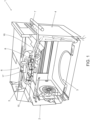
Figure 1 is a schematic view of a domestic appliance having a centrifugal cooling fan according to the present invention, with parts removed for clarity; -
Figure 2 is an exploded view of a centrifugal cooling fan according to the present invention, with parts removed for clarity; -
Figure 3 is a perspective view of a portion of the centrifugal cooling fan seen from a first perspective, with parts removed for clarity; and -
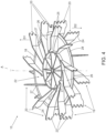
Figure 4 is a perspective view of a portion of the centrifugal cooling fan seen from a second perspective, with parts removed for clarity; and -
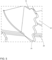
Figure 5 is an enlarged perspective view of a detail of the centrifugal cooling fan ofFigures 3 and4 , with parts removed for clarity. - With particular reference to
Figure 1 ,number 1 indicates as a whole a domestic appliance, preferentially a domestic oven, for the treatment, preferentially the thermal treatment, of food products. - In more detail,
domestic appliance 1 may comprise at least: - a
main body 2 comprising atreatment cavity 3 for the treatment, preferentially the thermal treatment, even more particular for the heating, of the food product withintreatment cavity 3; and - a
door 4 configured to selectively open or close an opening ofmain body 2 so as to selectively allow or impede access totreatment cavity 3. - Additionally,
main body 2 may comprise anelectronic compartment 5 within which electronic components ofdomestic appliance 1 are housed in. - According to some possible embodiments,
domestic appliance 1 may comprise one or more of: a microwave unit configured to treat the food product by means of microwaves and to introduce microwaves intotreatment cavity 3, a heat convection unit configured to create a flow of heat withintreatment cavity 3 and a steam generation unit configured to introduce steam intotreatment cavity 3. - E.g. in the case of the presence of a microwave unit, the microwave unit may be arranged within
electronic compartment 5. - According to some possible embodiments, one or more of the electronic components may be comprises by one or more of the microwave unit, the heat convection unit and the steam generation unit.
-
Domestic appliance 1 may comprise a control unit configured to control operation ofdomestic appliance 1 and being at least partially arranged withinelectronic compartment 5. - Furthermore,
domestic appliance 1 comprises acentrifugal cooling fan 6 configured to at least generate a cooling air flow withinelectronic compartment 5, and preferentially to also evacuate fluids (e.g. steam, air, and so on) fromtreatment cavity 3. Preferentially,centrifugal cooling fan 6 may be at least partially arranged withinelectronic compartment 3 and/or may be on fluidic connecting withtreatment cavity 3. - Preferentially,
main body 2 may comprise an evacuation hole andcentrifugal cooling fan 6 being in fluidic connection withtreatment cavity 3 through the evacuation hole. Preferentially,centrifugal cooling fan 6 may be configured to evacuate fluids fromtreatment chamber 3 through the evacuation hole. - According to some possible embodiments,
main body 2 may comprise one or more inlet holes configured to establish a fluidic connection between an outside space andelectronic compartment 3. Preferentially,centrifugal cooling fan 6 may be configured to generate a flow of cooling air from the outside space intoelectronic compartment 3 through the one or more inlet holes. - Additionally,
centrifugal cooling fan 6 may also be configured to generate a flow of fluids through anoutlet opening 7 out ofdomestic appliance 1, preferentiallymain body 2. E.g.outlet opening 7 may be arranged above (seeFigure 1 ) or, alternatively, below (not shown)door 4. - Moreover,
outlet opening 7 may have an elongated configuration. - Preferentially,
door 4 may comprise a flow channel andcentrifugal cooling fan 6 may also be configured to generate a flow of air from the outside space into and within the flow channel. - Additionally,
domestic appliance 1 may comprise aflow conduit 8 being in fluidic connection with the flow channel andcentrifugal cooling fan 6. Preferentially,centrifugal cooling fan 6 may be configured to generate the flow of air within the flow channel and into and through the flow conduit. - According to some preferred non-limiting embodiments,
centrifugal cooling fan 6 may comprise at least two inlets configured to draw fluids from different directions (e.g. from below and above). - With particular reference to
Figures 2 to 4 ,centrifugal cooling fan 6 comprises animpeller 15 configured to generate the respective drawing forces for generating (desired) fluid flows, preferentially through the respective two inlets. - Preferentially,
impeller 15 may be realized as a single piece, e.g. formed by molding. - Additionally,
centrifugal cooling fan 6 may also comprise afan housing 16housing impeller 15, and preferentially also an actuator 17 (e.g. an electric motor) configured to actuate a rotation ofimpeller 15 about a rotation axis A. In particular,fan housing 16 may comprise a seat andimpeller 15 may be arranged within the seat. - With particular reference to
Figures 2 to 4 ,impeller 15 comprises aseparation plate 18, a plurality offirst blades 19 extending fromseparation plate 18, preferentially into a first direction D1, and a plurality ofsecond blades 20 extending fromseparation plate 18, preferentially into a second direction D2 opposite to first direction D1. - In more detail,
separation plate 18 may comprise afirst face 21 and asecond face 22 opposed tofirst face 19. Moreover,first blades 19 may axial extending fromfirst face 19 andsecond blades 20 may axial extend fromsecond face 22. - Advantageously, each
first blade 19 and eachsecond blade 20 may comprise aserrated section 23. - In particular, each
first blade 19 and eachsecond blade 20 may comprise a trailingedge 24 and aleading edge 25. - Each trailing
edge 24 and/or eachleading edge 25 may comprise the respectiveserrated section 23. - Most preferentially, at least each trailing
edge 24 may comprise the respectiveserrated section 23. Additionally, also eachleading edge 25 may comprise a respective serrated section (not shown). - Already the presence of each
serrated section 23 contributes to a reduction of noise formation during use ofimpeller 15 in comparison to the knownimpellers 15. In order to further improve and to rely on synergistic effects,first blades 19 andsecond blade 20 are not aligned with respect to one another. - According to some preferred non-limiting embodiments, each
serrated section 23 may follow and/or have a sinusoidal shape. - In more detail, each
first blade 19 is interposed between two respectivesecond blades 20 and eachsecond blade 20 is interposed between two respectivefirst blades 19. - In particular, this is to be understood such that if
first blades 19 andsecond blades 20 would be projected onto a two-dimensional plane, the respective projections of eachfirst blade 19 are interposed between the respective projections of eachsecond blade 20 and the respective projections of eachsecond blade 20 are interposed between the respective projections of the respective twofirst blades 19. - According to some preferred non-limiting embodiments,
first blades 19 may be equally spaced about rotation axis A and alsosecond blades 20 may be equally spaced about rotation axis A. - Additionally and with respect to rotation axis A, the
respective trailing edge 24 of eachfirst blade 19 may be angularly displaced from therespective trailing edges 24 ofsecond blades 20 and therespective trailing edge 24 of eachsecond blade 20 may be angularly displaced from therespective trailing edges 24 offirst blades 19. - In more detail, the
respective trailing edge 24 of eachfirst blade 19 may be arranged at a respective first angular position and therespective trailing edge 24 of eachsecond blade 20 may be arranged at a respective second angular position with respect to rotation axis A. Preferentially, the respective second angular positions are angularly displaced from the respective first angular positions. - With particular reference to
Figure 3 and4 , eachfirst blade 19 and eachsecond blade 20 may comprises afirst end portion 26 in contact with, preferentially being integral to,separation plate 18 and afree end portion 27 opposite tofirst end portion 26. - In more detail, the respective
free end portions 27 offirst blades 19 are distanced fromfirst face 21 and the respectivefree end portions 27 ofsecond blades 20 are distanced fromsecond face 22. - According to some preferred non-limiting embodiments, each
first blade 19 and eachsecond blade 20 may radially protrude away fromseparation plate 18; i.e. trailingedges 24 offirst blades 19 and trailingedges 24 ofsecond blades 20 may be further distanced from a center ofseparation plate 18 than anouter edge 28 ofseparation plate 18. - In more detail, the
respective trailing edges 24 offirst blades 19 may define a first circle of a first diameter and therespective trailing edges 24 ofsecond blades 20 may define a second circle of a second diameter. Moreover, an outer diameter ofseparation plate 18 may be smaller than the first diameter and the second diameter. - In particular, the portions of each trailing
edge 24 being farthest from a center ofseparation plate 18 may lie on respective the first circle or the second circle. - Most preferentially, the first diameter and the second diameter may equal one another.
- Most preferentially, the diameter of
separation plate 18 may be than the first diameter and the second diameter by at least a factor of 0,9, preferentially of at least by afactor 0,8. - Moreover, a respective height of each first blade 19 (from first face 21) and of each second blade 20 (from second face 22) may increase towards the
respective trailing edge 24 and/or decreases towards the center ofseparation plate 18. - Clearly, changes may be made to
centrifugal cooling fan 6 and/ordomestic appliance 1 without, however, departing from the scope of the present invention. -
- 1
- Domestic Appliance
- 2
- Main Body
- 3
- Treatment Cavity
- 4
- Door
- 5
- Electronic Compartment
- 6
- Centrifugal Cooling Fan
- 7
- Outlet Opening
- 8
- Flow Conduit
- 15
- Impeller
- 16
- Housing
- 17
- Actuator
- 18
- Separation Plate
- 19
- First Blades
- 20
- Second Blades
- 21
- First Face
- 22
- Second Face
- 23
- Serrated Section
- 24
- Trailing Edge
- 25
- Leading Edge
- 26
- First End Portion
- 27
- Free End Portion
- 28
- Outer Edge
- A
- Rotation Axis
- D1
- First Direction
- D2
- Second Direction
Claims (15)
- Centrifugal cooling fan (6) for a domestic appliance (1) comprising at least an impeller (15), the impeller (15) having:- a separation plate (18) having a first face (21) and a second face (22) opposed to the first face (21);- a plurality of first blades (19) axially extending from the first face (21) of the separation plate (18); and- a plurality of second blades (20) axially extending from the second face (22) of the separation plate (18); wherein each first blade (19) and each second blade (20) comprises a trailing edge (24) and a leading edge (25); wherein each trailing edge (24) and/or each leading edge (25) comprises a serrated section (23);wherein the plurality of first blades (19) is misaligned with the plurality of second blades (20).
- Centrifugal cooling fan according to claim 1, wherein each first blade (19) is interposed between two respective second blades (20) and each second blade (20) is interposed between two respective first blades (19).
- Centrifugal cooling fan according to claim 1 or 2, wherein the first blades (19) of the plurality of first blades (19) are equally spaced about a rotation axis (A) of the impeller (15);wherein the second blades (20) of the plurality of second blades (20) are equally spaced about the rotation axis (A) ;wherein the respective trailing edge (24) of each first blade (19) is angularly displaced from the respective trailing edges (24) of the second blades (20) and the respective trailing edge (24) of each second blade (20) is angularly displaced from the respective trailing edges (24) of the first blades (19).
- Centrifugal cooling fan according to claim 3, wherein the respective trailing edge (24) of each first blade (19) is arranged at a respective first angular position and the respective trailing edge (24) of each second blade (20) is arranged at a respective second angular position with respect to the rotation axis (A); wherein the respective second angular positions are angularly displaced from the respective first angular positions.
- Centrifugal cooling fan according to any one of the preceding claims, wherein each first blade (19) and each second blade (20) comprises a first end portion (26) in contact with the separation plate (18) and a free end portion (27) opposite to the first end portion (26).
- Centrifugal cooling fan according to any one of the preceding claims, wherein the first blades (19) and the second blades (20) radially protrude away from the separation plate (18).
- Centrifugal cooling fan according to any one of the preceding claims, wherein the plurality of trailing edges (24) of the first blades (19) define a first circle of a first diameter and wherein the plurality of trailing edges (24) of the second blades (20) define a second circle of a second diameter;
wherein an outer diameter of the separation plate (18) is smaller than the first diameter and the second diameter. - Centrifugal cooling fan according to claim 7, wherein the first diameter and the second diameter equal one another.
- Centrifugal cooling fan according to claim 8, wherein the diameter of the separation plate is smaller than the first diameter and the second diameter by at least a factor of 0,9, preferentially of at least by a factor 0,8.
- Centrifugal cooling fan according to any one of the preceding claims, wherein a respective height of each first blade (19) and of each second blade (20) increases towards the trailing edge (24) and/or decreases towards a center of the separation plate (18).
- Centrifugal cooling fan according to any one of the preceding claims, wherein each serrated section (23) presents a sinusoidal shape.
- Centrifugal cooling fan according to any one of the preceding claims, wherein the impeller (15) is formed in a single piece.
- Domestic appliance (1) for the thermal treatment of food products comprising a centrifugal cooling fan (6) according to any one of the preceding claims.
- Domestic appliance according to claim 13, further comprising one or more electrical components arranged within an electronic compartment (5) of the domestic appliance (1);
wherein the centrifugal cooling fan (6) is configured to generate a cooling air stream for cooling the one or more electrical components and to direct the air out of an outlet opening (7) of the domestic appliance (1). - Domestic appliance according to claim 13 or 14, further comprising a treatment cavity (3) for retaining the food product and having an opening for introducing and/or removing the food product;wherein the domestic appliance (1) further comprises a door (4) for selectively closing and opening the opening; wherein the door (4) comprises a flow path and the centrifugal cooling fan (6) is configured to create an air flow through the flow path; and/orwherein the treatment cavity (3) comprises at least one evacuation hole and the centrifugal cooling fan (6) is configured to evacuate fluids from the treatment cavity (3) and to direct the fluids out of an outlet opening (7) of the domestic appliance (1).
Priority Applications (2)
| Application Number | Priority Date | Filing Date | Title |
|---|---|---|---|
| EP23202513.0A EP4538538A1 (en) | 2023-10-09 | 2023-10-09 | Centrifugal cooling fan for a domestic appliance and domestic appliance having a centrifugal cooling fan |
| PCT/EP2024/074926 WO2025078083A1 (en) | 2023-10-09 | 2024-09-06 | Centrifugal cooling fan for a domestic appliance and domestic appliance having a centrifugal cooling fan |
Applications Claiming Priority (1)
| Application Number | Priority Date | Filing Date | Title |
|---|---|---|---|
| EP23202513.0A EP4538538A1 (en) | 2023-10-09 | 2023-10-09 | Centrifugal cooling fan for a domestic appliance and domestic appliance having a centrifugal cooling fan |
Publications (1)
| Publication Number | Publication Date |
|---|---|
| EP4538538A1 true EP4538538A1 (en) | 2025-04-16 |
Family
ID=88297218
Family Applications (1)
| Application Number | Title | Priority Date | Filing Date |
|---|---|---|---|
| EP23202513.0A Pending EP4538538A1 (en) | 2023-10-09 | 2023-10-09 | Centrifugal cooling fan for a domestic appliance and domestic appliance having a centrifugal cooling fan |
Country Status (2)
| Country | Link |
|---|---|
| EP (1) | EP4538538A1 (en) |
| WO (1) | WO2025078083A1 (en) |
Citations (7)
| Publication number | Priority date | Publication date | Assignee | Title |
|---|---|---|---|---|
| GB2105791A (en) * | 1981-09-22 | 1983-03-30 | Gebhardt Gmbh Wilhelm | >Centrifugal fan |
| US20020057965A1 (en) * | 2000-11-16 | 2002-05-16 | Delta Electronics Inc. | Centrifugal fan |
| US8221069B2 (en) * | 2006-03-17 | 2012-07-17 | Panasonic Corporation | Multi-blade fan |
| US9145897B2 (en) * | 2011-10-04 | 2015-09-29 | Asia Vital Components Co., Ltd. | Blade structure for centrifugal fan |
| US20160033143A1 (en) * | 2014-08-01 | 2016-02-04 | Samsung Electronics Co., Ltd. | Oven and door assembly applied to the oven |
| CN207212709U (en) * | 2017-09-11 | 2018-04-10 | 加丁(天津)科技有限公司 | A kind of low-noise centrifugal fan, air cleaning unit provided with sawtooth trailing edge blade |
| CN116292340A (en) * | 2023-05-11 | 2023-06-23 | 佛山市南海九洲普惠风机有限公司 | Multi-wing centrifugal fan |
-
2023
- 2023-10-09 EP EP23202513.0A patent/EP4538538A1/en active Pending
-
2024
- 2024-09-06 WO PCT/EP2024/074926 patent/WO2025078083A1/en active Pending
Patent Citations (7)
| Publication number | Priority date | Publication date | Assignee | Title |
|---|---|---|---|---|
| GB2105791A (en) * | 1981-09-22 | 1983-03-30 | Gebhardt Gmbh Wilhelm | >Centrifugal fan |
| US20020057965A1 (en) * | 2000-11-16 | 2002-05-16 | Delta Electronics Inc. | Centrifugal fan |
| US8221069B2 (en) * | 2006-03-17 | 2012-07-17 | Panasonic Corporation | Multi-blade fan |
| US9145897B2 (en) * | 2011-10-04 | 2015-09-29 | Asia Vital Components Co., Ltd. | Blade structure for centrifugal fan |
| US20160033143A1 (en) * | 2014-08-01 | 2016-02-04 | Samsung Electronics Co., Ltd. | Oven and door assembly applied to the oven |
| CN207212709U (en) * | 2017-09-11 | 2018-04-10 | 加丁(天津)科技有限公司 | A kind of low-noise centrifugal fan, air cleaning unit provided with sawtooth trailing edge blade |
| CN116292340A (en) * | 2023-05-11 | 2023-06-23 | 佛山市南海九洲普惠风机有限公司 | Multi-wing centrifugal fan |
Also Published As
| Publication number | Publication date |
|---|---|
| WO2025078083A1 (en) | 2025-04-17 |
Similar Documents
| Publication | Publication Date | Title |
|---|---|---|
| CN107269591A (en) | Improved fan, in particular for kitchen fume and vapour suction systems, and suction system incorporating same | |
| EP3133295B1 (en) | Diffuser, airflow generating apparatus, and electrical device | |
| US10900360B2 (en) | Fan, outdoor unit, and refrigeration cycle apparatus | |
| JP5280527B2 (en) | Heating device | |
| US6861632B2 (en) | Microwave oven | |
| CN112515493A (en) | Cooking utensil | |
| WO2025078083A1 (en) | Centrifugal cooling fan for a domestic appliance and domestic appliance having a centrifugal cooling fan | |
| KR101261669B1 (en) | Microwave range having hood | |
| CN113491436A (en) | Wind-guiding heat abstractor and cooking utensil | |
| JP2012002468A (en) | Heating apparatus | |
| WO2025094058A1 (en) | Cooking appliance | |
| KR20000051144A (en) | Ventilation apparatus of over the range | |
| EP3059504A1 (en) | Kitchen oven | |
| US10865797B2 (en) | Local ventilation equipment and blower therein | |
| KR101460358B1 (en) | Microwave | |
| KR20040059039A (en) | Ventilation hooded microwave oven | |
| CN210531228U (en) | Impeller and Yuba of a multi-blade centrifugal fan | |
| KR100424320B1 (en) | sirocco fan having Eccentric scroll housing | |
| KR100676135B1 (en) | Heat cooker with double convection fan | |
| CN223958644U (en) | Air-out blade and cooking equipment | |
| JP5045563B2 (en) | Cooker | |
| CN222870318U (en) | An oven | |
| JP5369913B2 (en) | Heating device | |
| KR100897810B1 (en) | Blower and cooking equipment using the same | |
| KR100292481B1 (en) | Cooling structure for microwave oven |
Legal Events
| Date | Code | Title | Description |
|---|---|---|---|
| PUAI | Public reference made under article 153(3) epc to a published international application that has entered the european phase |
Free format text: ORIGINAL CODE: 0009012 |
|
| STAA | Information on the status of an ep patent application or granted ep patent |
Free format text: STATUS: THE APPLICATION HAS BEEN PUBLISHED |
|
| AK | Designated contracting states |
Kind code of ref document: A1 Designated state(s): AL AT BE BG CH CY CZ DE DK EE ES FI FR GB GR HR HU IE IS IT LI LT LU LV MC ME MK MT NL NO PL PT RO RS SE SI SK SM TR |
|
| STAA | Information on the status of an ep patent application or granted ep patent |
Free format text: STATUS: REQUEST FOR EXAMINATION WAS MADE |
|
| 17P | Request for examination filed |
Effective date: 20251016 |