EP4538506A1 - Fan drive gear system rotating oil baffle - Google Patents
Fan drive gear system rotating oil baffle Download PDFInfo
- Publication number
- EP4538506A1 EP4538506A1 EP24201764.8A EP24201764A EP4538506A1 EP 4538506 A1 EP4538506 A1 EP 4538506A1 EP 24201764 A EP24201764 A EP 24201764A EP 4538506 A1 EP4538506 A1 EP 4538506A1
- Authority
- EP
- European Patent Office
- Prior art keywords
- baffle
- aft
- lubricant
- gutter
- drive gear
- Prior art date
- Legal status (The legal status is an assumption and is not a legal conclusion. Google has not performed a legal analysis and makes no representation as to the accuracy of the status listed.)
- Pending
Links
Images



Classifications
-
- F—MECHANICAL ENGINEERING; LIGHTING; HEATING; WEAPONS; BLASTING
- F01—MACHINES OR ENGINES IN GENERAL; ENGINE PLANTS IN GENERAL; STEAM ENGINES
- F01D—NON-POSITIVE DISPLACEMENT MACHINES OR ENGINES, e.g. STEAM TURBINES
- F01D25/00—Component parts, details, or accessories, not provided for in, or of interest apart from, other groups
- F01D25/18—Lubricating arrangements
-
- F—MECHANICAL ENGINEERING; LIGHTING; HEATING; WEAPONS; BLASTING
- F02—COMBUSTION ENGINES; HOT-GAS OR COMBUSTION-PRODUCT ENGINE PLANTS
- F02C—GAS-TURBINE PLANTS; AIR INTAKES FOR JET-PROPULSION PLANTS; CONTROLLING FUEL SUPPLY IN AIR-BREATHING JET-PROPULSION PLANTS
- F02C7/00—Features, components parts, details or accessories, not provided for in, or of interest apart form groups F02C1/00 - F02C6/00; Air intakes for jet-propulsion plants
- F02C7/06—Arrangements of bearings; Lubricating
-
- F—MECHANICAL ENGINEERING; LIGHTING; HEATING; WEAPONS; BLASTING
- F02—COMBUSTION ENGINES; HOT-GAS OR COMBUSTION-PRODUCT ENGINE PLANTS
- F02C—GAS-TURBINE PLANTS; AIR INTAKES FOR JET-PROPULSION PLANTS; CONTROLLING FUEL SUPPLY IN AIR-BREATHING JET-PROPULSION PLANTS
- F02C7/00—Features, components parts, details or accessories, not provided for in, or of interest apart form groups F02C1/00 - F02C6/00; Air intakes for jet-propulsion plants
- F02C7/36—Power transmission arrangements between the different shafts of the gas turbine plant, or between the gas-turbine plant and the power user
-
- F—MECHANICAL ENGINEERING; LIGHTING; HEATING; WEAPONS; BLASTING
- F16—ENGINEERING ELEMENTS AND UNITS; GENERAL MEASURES FOR PRODUCING AND MAINTAINING EFFECTIVE FUNCTIONING OF MACHINES OR INSTALLATIONS; THERMAL INSULATION IN GENERAL
- F16H—GEARING
- F16H57/00—General details of gearing
- F16H57/04—Features relating to lubrication or cooling or heating
- F16H57/042—Guidance of lubricant
- F16H57/0421—Guidance of lubricant on or within the casing, e.g. shields or baffles for collecting lubricant, tubes, pipes, grooves, channels or the like
- F16H57/0423—Lubricant guiding means mounted or supported on the casing, e.g. shields or baffles for collecting lubricant, tubes or pipes
-
- F—MECHANICAL ENGINEERING; LIGHTING; HEATING; WEAPONS; BLASTING
- F16—ENGINEERING ELEMENTS AND UNITS; GENERAL MEASURES FOR PRODUCING AND MAINTAINING EFFECTIVE FUNCTIONING OF MACHINES OR INSTALLATIONS; THERMAL INSULATION IN GENERAL
- F16H—GEARING
- F16H57/00—General details of gearing
- F16H57/04—Features relating to lubrication or cooling or heating
- F16H57/042—Guidance of lubricant
- F16H57/0427—Guidance of lubricant on rotary parts, e.g. using baffles for collecting lubricant by centrifugal force
-
- F—MECHANICAL ENGINEERING; LIGHTING; HEATING; WEAPONS; BLASTING
- F16—ENGINEERING ELEMENTS AND UNITS; GENERAL MEASURES FOR PRODUCING AND MAINTAINING EFFECTIVE FUNCTIONING OF MACHINES OR INSTALLATIONS; THERMAL INSULATION IN GENERAL
- F16H—GEARING
- F16H57/00—General details of gearing
- F16H57/04—Features relating to lubrication or cooling or heating
- F16H57/045—Lubricant storage reservoirs, e.g. reservoirs in addition to a gear sump for collecting lubricant in the upper part of a gear case
-
- F—MECHANICAL ENGINEERING; LIGHTING; HEATING; WEAPONS; BLASTING
- F16—ENGINEERING ELEMENTS AND UNITS; GENERAL MEASURES FOR PRODUCING AND MAINTAINING EFFECTIVE FUNCTIONING OF MACHINES OR INSTALLATIONS; THERMAL INSULATION IN GENERAL
- F16H—GEARING
- F16H57/00—General details of gearing
- F16H57/04—Features relating to lubrication or cooling or heating
- F16H57/0457—Splash lubrication
-
- F—MECHANICAL ENGINEERING; LIGHTING; HEATING; WEAPONS; BLASTING
- F16—ENGINEERING ELEMENTS AND UNITS; GENERAL MEASURES FOR PRODUCING AND MAINTAINING EFFECTIVE FUNCTIONING OF MACHINES OR INSTALLATIONS; THERMAL INSULATION IN GENERAL
- F16H—GEARING
- F16H57/00—General details of gearing
- F16H57/04—Features relating to lubrication or cooling or heating
- F16H57/0467—Elements of gearings to be lubricated, cooled or heated
- F16H57/0479—Gears or bearings on planet carriers
-
- F—MECHANICAL ENGINEERING; LIGHTING; HEATING; WEAPONS; BLASTING
- F16—ENGINEERING ELEMENTS AND UNITS; GENERAL MEASURES FOR PRODUCING AND MAINTAINING EFFECTIVE FUNCTIONING OF MACHINES OR INSTALLATIONS; THERMAL INSULATION IN GENERAL
- F16H—GEARING
- F16H57/00—General details of gearing
- F16H57/04—Features relating to lubrication or cooling or heating
- F16H57/048—Type of gearings to be lubricated, cooled or heated
- F16H57/0482—Gearings with gears having orbital motion
- F16H57/0486—Gearings with gears having orbital motion with fixed gear ratio
-
- F—MECHANICAL ENGINEERING; LIGHTING; HEATING; WEAPONS; BLASTING
- F05—INDEXING SCHEMES RELATING TO ENGINES OR PUMPS IN VARIOUS SUBCLASSES OF CLASSES F01-F04
- F05D—INDEXING SCHEME FOR ASPECTS RELATING TO NON-POSITIVE-DISPLACEMENT MACHINES OR ENGINES, GAS-TURBINES OR JET-PROPULSION PLANTS
- F05D2220/00—Application
- F05D2220/30—Application in turbines
- F05D2220/36—Application in turbines specially adapted for the fan of turbofan engines
-
- F—MECHANICAL ENGINEERING; LIGHTING; HEATING; WEAPONS; BLASTING
- F05—INDEXING SCHEMES RELATING TO ENGINES OR PUMPS IN VARIOUS SUBCLASSES OF CLASSES F01-F04
- F05D—INDEXING SCHEME FOR ASPECTS RELATING TO NON-POSITIVE-DISPLACEMENT MACHINES OR ENGINES, GAS-TURBINES OR JET-PROPULSION PLANTS
- F05D2260/00—Function
- F05D2260/40—Transmission of power
- F05D2260/403—Transmission of power through the shape of the drive components
- F05D2260/4031—Transmission of power through the shape of the drive components as in toothed gearing
- F05D2260/40311—Transmission of power through the shape of the drive components as in toothed gearing of the epicyclical, planetary or differential type
-
- F—MECHANICAL ENGINEERING; LIGHTING; HEATING; WEAPONS; BLASTING
- F05—INDEXING SCHEMES RELATING TO ENGINES OR PUMPS IN VARIOUS SUBCLASSES OF CLASSES F01-F04
- F05D—INDEXING SCHEME FOR ASPECTS RELATING TO NON-POSITIVE-DISPLACEMENT MACHINES OR ENGINES, GAS-TURBINES OR JET-PROPULSION PLANTS
- F05D2260/00—Function
- F05D2260/98—Lubrication
-
- F—MECHANICAL ENGINEERING; LIGHTING; HEATING; WEAPONS; BLASTING
- F16—ENGINEERING ELEMENTS AND UNITS; GENERAL MEASURES FOR PRODUCING AND MAINTAINING EFFECTIVE FUNCTIONING OF MACHINES OR INSTALLATIONS; THERMAL INSULATION IN GENERAL
- F16H—GEARING
- F16H57/00—General details of gearing
- F16H57/08—General details of gearing of gearings with members having orbital motion
- F16H57/082—Planet carriers
Definitions
- the turbine engine assembly also includes at least one baffle that is attached to the carrier that is configured to impart a momentum on expelled lubricant or oil, a fixed gutter that is disposed radially outside the at least one baffle and is configured to receive lubricant or oil that is exhausted from the at least one baffle, and a fan shaft that is rotatable about the axis and configured to be driven by the carrier.
- the aft direction may be the defined by the side of the fan drive gear system on which the engine shaft drives the sun gear.
- An opposite, forward direction may be defined by the side of the fan drive gear system on which the fan shaft is coupled to the carrier.
- the forward gutter and the aft gutter each include a channel where oil is received from a corresponding one of the forward baffle and the aft baffle and a sealing surface for generating a seal with a seal that is attached to a corresponding one of the forward baffle and the aft baffle.
- the accumulation portion includes an axial length that corresponds with an axial length of the channel of a corresponding one of the forward gutter and the aft gutter.
- the forward and aft directions may be the defined by the intended direction of travel of the gas turbine engine.
- the aft direction may be the defined by the side of the fan drive gear system on which an engine shaft drives the gear system.
- An opposite, forward direction may be defined by the side of the fan drive gear system on which a fan shaft is coupled to the carrier.
- the gas turbine engine 20 is disclosed herein as a two-spool turbofan that generally incorporates a fan section 22, a compressor section 24, a combustor section 26 and a turbine section 28.
- the fan section 22 drives air along a bypass flow path B in a bypass duct defined within a nacelle 18, and also drives air along a core flow path C for compression and communication into the combustor section 26 then expansion through the turbine section 28.
- a mid-turbine frame 58 of the engine static structure 36 may be arranged generally between the high pressure turbine 54 and the low pressure turbine 46.
- the mid-turbine frame 58 further supports bearing systems 38 in the turbine section 28.
- the inner shaft 40 and the outer shaft 50 are concentric and rotate via bearing systems 38 about the engine central longitudinal axis A which is collinear with their longitudinal axes.
- the fan drive gear system 48 may be located aft of the low pressure compressor 44, or aft of the combustor section 26 or even aft of turbine section 28, and fan section 22 may be positioned forward or aft of the fan drive gear system 48.
- Centrifugal forces impart radially outward momentum on expelled lubricant.
- the outward momentum drives expelled lubricant, schematically shown at 118, radially outward in each of the baffles 88, 90.
- the baffles 88, 90 rotate with the carrier 82 and further impart radially outward momentum that drives lubricant radially outward toward the forward and aft gutters 96, 98.
Landscapes
- Engineering & Computer Science (AREA)
- General Engineering & Computer Science (AREA)
- Mechanical Engineering (AREA)
- Chemical & Material Sciences (AREA)
- Combustion & Propulsion (AREA)
- General Details Of Gearings (AREA)
Abstract
A fan drive gear system for a turbine engine includes a sun gear (78) that is configured to be driven by an engine shaft (40) that is rotatable about an axis (A), a plurality of intermediate gears (80) that are intermeshed with the sun gear (78), a ring gear (84) that is engaged with the plurality of intermediate gears (80), the ring gear (84) is configured for attachment to a static structure (76), a carrier (82) that supports rotation of the plurality of intermediate gears (80), the carrier configured for rotation about the axis (A), at least one baffle (88,90) that is attached to the carrier (82) and configured to impart a momentum on expelled lubricant, a fixed gutter (96,98) that is disposed radially outside the at least one baffle (88,90) and is configured to receive lubricant that is exhausted from the at least one baffle (88,90), and a fan shaft that (62) is rotatable about the axis (A) and configured to be driven by the carrier (82).
Description
- The present disclosure (invention) relates generally to an aircraft propulsion system that includes a fan drive gear system.
- A turbine engine typically includes a fan section, a compressor section, a combustor section, and a turbine section. A speed reduction device such as an epicyclical gear assembly may be utilized to drive the fan section such that the fan section may rotate at a speed different than the turbine section so as to increase the overall propulsive efficiency of the engine. A carrier may support a plurality of planetary gears and rotate about an engine axis. Rotation of the carrier can present challenges for recovering lubricant expelled from the gear system during operation. Turbine engine manufacturers continue to seek further improvements to engine performance including improvements to thermal, transfer and propulsive efficiencies.
- A turbine engine assembly according to an aspect of the present invention includes, among other possible things, a fan drive gear system including a sun gear that is configured to be driven by an engine shaft that is rotatable about an axis, a plurality of intermediate gears that are intermeshed with the sun gear, a ring gear assembly that is engaged with the plurality of intermediate gears, the ring gear is configured for attachment to a static structure, a carrier that supports rotation of the plurality of intermediate gears, the carrier is configured for rotation about the axis. The turbine engine assembly also includes at least one baffle that is attached to the carrier that is configured to impart a momentum on expelled lubricant or oil, a fixed gutter that is disposed radially outside the at least one baffle and is configured to receive lubricant or oil that is exhausted from the at least one baffle, and a fan shaft that is rotatable about the axis and configured to be driven by the carrier.
- Optionally, and in accordance with the above, the at least one baffle includes a plurality of openings that extend through a radially facing outer wall.
- Optionally, and in accordance with any of the above, the fixed gutter includes an annular channel for receiving oil from the at least one baffle and a seal surface. A seal is attached to the at least one baffle and seals against the seal surface.
- Optionally, and in accordance with any of the above, the fixed gutter includes at least one outlet for communicating oil to an auxiliary lubrication system.
- Optionally, and in accordance with any of the above, the carrier includes a forward face and an aft face and the at least one baffle includes a forward baffle that is attached to the forward face and an aft baffle that is attached to the aft face. The fixed gutter includes a forward gutter that is radially outside the forward baffle and an aft gutter that is radially outside the aft baffle.
- The aft direction may be the defined by the side of the fan drive gear system on which the engine shaft drives the sun gear. An opposite, forward direction may be defined by the side of the fan drive gear system on which the fan shaft is coupled to the carrier.
- Optionally, and in accordance with any of the above, the forward gutter and the aft gutter each include a channel where oil is received from a corresponding one of the forward baffle and the aft baffle and a sealing surface for generating a seal with a seal that is attached to a corresponding one of the forward baffle and the aft baffle.
- Optionally, and in accordance with any of the above, the channel is annular about the axis and includes a "V" shape in cross-section.
- Optionally, and in accordance with any of the above, each of the forward gutter and the aft gutter includes an outlet for communicating oil to an auxiliary reservoir.
- Optionally, and in accordance with any of the above, each of the forward baffle and the aft baffle includes a radially inward extending capture portion and an annular accumulation portion. Captured lubricant is directed radially outward by the capture portion into the accumulation portion where a circumferential momentum is imparted into the lubricant.
- Optionally, and in accordance with any of the above, the outlet extends tangential to an outer radial surface to a corresponding one of the forward gutter and the aft gutter to conserve momentum that is generated in the lubricant by a corresponding one of the forward and aft baffles.
- Optionally, and in accordance with any of the above, each of the intermediate gears is supported by a journal bearing that is supported within the carrier and lubricant expelled from each of the journal bearings is directed through the at least one baffle.
- Optionally, and in accordance with any of the above, the turbine engine assembly may further comprise a static engine structure, a fan section that includes a fan shaft that is coupled to a hub that supports a plurality of blades that are rotatable about an axis, a primary lubricant system that communicates lubricant to the fan drive gear system, and an auxiliary lubricant system that includes an auxiliary reservoir that is configured to receive lubricant that is expelled from the fan drive gear system and communicated through the fixed gutter.
- A turbine engine assembly according to another aspect of the present invention includes, among other possible things, a static engine structure, a fan section that includes a fan shaft that is coupled to a hub that supports a plurality of blades that are rotatable about an axis, a fan drive gear system that includes a sun gear that is configured to be driven by an engine shaft that is rotatable about the axis, a plurality of intermediate gears, a ring gear assembly that is fixed to the engine static structure, a carrier that supports rotation of the plurality of intermediate gears, the carrier is rotatable about the axis and coupled to drive the fan shaft, and a forward baffle that is attached to a forward face of the carrier and configured to impart a momentum on lubricant that is expelled forward of the gear system. An aft baffle is attached to an aft face of the carrier and configured to impart moment on lubricant that is expelled aft of the gear system. A forward gutter is disposed radially outside the forward baffle and fixed to the engine static structure, the forward gutter is configured to receive lubricant that is exhausted from the forward baffle. An aft gutter is disposed radially outside the aft baffle and fixed to the engine static structure, the aft gutter is configured to receive lubricant that is exhausted from the forward baffle. A primary lubricant system communicates lubricant to the fan drive gear system, and an auxiliary lubricant system includes an auxiliary reservoir that is configured to receive lubricant that is expelled from the fan drive gear system and communicated through the fixed gutter.
- The aft direction may be the defined by the side of the fan drive gear system on which the engine shaft drives the sun gear. An opposite, forward direction may be defined by the side of the fan drive gear system on which the fan shaft is coupled to the carrier.
- Optionally, and in accordance with any of the above, the forward gutter and the aft gutter each include a channel where lubricant is received from a corresponding one of the forward baffle and the aft baffle and a sealing surface for generating a seal with a seal that is attached to a corresponding one of the forward baffle and the aft baffle.
- Optionally, and in accordance with any of the above, each of the forward baffle and the aft baffle includes a radially inward extending capture portion and an annular accumulation portion. Captured lubricant is directed radially outward by the capture portion into the accumulation portion where a circumferential momentum is imparted into the lubricant.
- Optionally, and in accordance with any of the above, the accumulation portion includes an axial length that corresponds with an axial length of the channel of a corresponding one of the forward gutter and the aft gutter.
- Optionally, and in accordance with any of the above, the channel is annular about the axis and includes a "V" shape in cross-section.
- Optionally, and in accordance with any of the above, each of the forward gutter and the aft gutter includes an outlet for communicating lubricant to the auxiliary reservoir. The outlet extends tangential to an outer radial surface to a corresponding one of the forward gutter and the aft gutter to conserve momentum that is generated in the lubricant by a corresponding one of the forward and aft baffles.
- A lubrication system for a gas turbine engine according to another aspect of the present invention includes, among other possible things, a forward baffle that is configured for attachment to a forward face of a rotating carrier and configured to impart a momentum on lubricant that is expelled forward of a fan drive gear system. An aft baffle is configured for attachment to an aft face of the rotating carrier and configured to impart moment on lubricant that is expelled aft of the fan drive gear system. A forward gutter is disposed radially outside the forward baffle and configured to be fixed to an engine static structure, the forward gutter is configured to receive lubricant that is exhausted from the forward baffle. An aft gutter is disposed radially outside the aft baffle and configured to be fixed to the engine static structure, the aft gutter is configured to receive lubricant that is exhausted from the forward baffle. A primary lubricant system communicates lubricant to the fan drive gear system, and an auxiliary lubricant system includes an auxiliary reservoir that is configured to receive lubricant that is expelled from the fan drive gear system and communicated through the fixed gutter.
- The forward and aft directions may be the defined by the intended direction of travel of the gas turbine engine.
- The aft direction may be the defined by the side of the fan drive gear system on which an engine shaft drives the gear system. An opposite, forward direction may be defined by the side of the fan drive gear system on which a fan shaft is coupled to the carrier.
- Optionally, and in accordance with any of the above, each of the forward baffle and the aft baffle includes a radially inward extending capture portion and an annular accumulation portion. Captured lubricant is directed radially outward by the capture portion into the accumulation portion where a circumferential momentum is imparted into the lubricant.
- Optionally, and in accordance with any of the above, each of the forward gutter and the aft gutter includes an outlet for communicating lubricant to the auxiliary reservoir, the outlet extends tangential to an outer radial surface to a corresponding one of the forward gutter and the aft gutter to conserve momentum that is generated in the lubricant by a corresponding one of the forward and aft baffles.
- Although the different examples have the specific components shown in the illustrations, embodiments of this invention are not limited to those particular combinations. It is possible to use some of the components or features from one of the examples in combination with features or components from another one of the examples.
- These and other features disclosed herein can be best understood from the following specification and drawings, the following of which is a brief description.
-
-
Figure 1 is a schematic view of an example gas turbine engine including a planetary fan drive gear system. -
Figure 2 is a schematic view of an example fan drive gear system. -
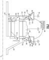
Figure 3 is a schematic view of a lubricant recovery system of the example fan drive gear system. -
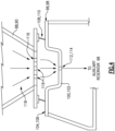
Figure 4 is an enlarged schematic view of an interface between a rotating baffle and a static gutter. -
Figure 5 is a schematic view of the example fan drive gear system illustrating an example lubricant flow embodiment. -
Figure 1 schematically illustrates agas turbine engine 20 with an epicyclic fandrive gear system 48 having a rotating carrier with rotating lubricant baffles for capturing and directing expelled lubricant to an auxiliary reservoir. - The
gas turbine engine 20 is disclosed herein as a two-spool turbofan that generally incorporates afan section 22, acompressor section 24, acombustor section 26 and aturbine section 28. Thefan section 22 drives air along a bypass flow path B in a bypass duct defined within anacelle 18, and also drives air along a core flow path C for compression and communication into thecombustor section 26 then expansion through theturbine section 28. Although depicted as a two-spool turbofan gas turbine engine in the disclosed non-limiting embodiment, it should be understood that the concepts described herein are not limited to use with two-spool turbofans as the teachings may be applied to other types of turbine engines including three-spool architectures, turbofans, turboprop, open rotor configurations and any other gas turbine engine architecture. - The
exemplary engine 20 generally includes alow speed spool 30 and ahigh speed spool 32 mounted for rotation about an engine central longitudinal axis A relative to an enginestatic structure 36 viaseveral bearing systems 38. It should be understood that various bearingsystems 38 at various locations may alternatively or additionally be provided, and the location of bearingsystems 38 may be varied as appropriate to the application. - The
low speed spool 30 generally includes aninner shaft 40 that interconnects, a first (or low) pressure compressor 44 and a first (or low)pressure turbine 46. Theinner shaft 40 is connected to afan section 22 through a speed change mechanism, which in exemplarygas turbine engine 20 is illustrated as the fandrive gear system 48 to drive thefan section 22 at a lower speed than thelow speed spool 30. Thehigh speed spool 32 includes anouter shaft 50 that interconnects a second (or high)pressure compressor 52 and a second (or high)pressure turbine 54. Thelow pressure turbine 46 includes a plurality ofturbine rotors 34. Acombustor 56 is arranged inexemplary gas turbine 20 between thehigh pressure compressor 52 and thehigh pressure turbine 54. Amid-turbine frame 58 of the enginestatic structure 36 may be arranged generally between thehigh pressure turbine 54 and thelow pressure turbine 46. Themid-turbine frame 58 furthersupports bearing systems 38 in theturbine section 28. Theinner shaft 40 and theouter shaft 50 are concentric and rotate via bearingsystems 38 about the engine central longitudinal axis A which is collinear with their longitudinal axes. - The core airflow is compressed by the low pressure compressor 44 then the
high pressure compressor 52, mixed and burned with fuel in thecombustor 56, then expanded over thehigh pressure turbine 54 andlow pressure turbine 46. Themid-turbine frame 58 includesairfoils 60 which are in the core airflow path C. Theturbines low speed spool 30 andhigh speed spool 32 in response to the expansion. It will be appreciated that each of the positions of thefan section 22,compressor section 24,combustor section 26,turbine section 28, and fandrive gear system 48 may be varied. For example, the fandrive gear system 48 may be located aft of the low pressure compressor 44, or aft of thecombustor section 26 or even aft ofturbine section 28, andfan section 22 may be positioned forward or aft of the fandrive gear system 48. - The
engine 20 in one example is a high-bypass geared aircraft engine. theexample engine 20 includes a bypass ratio greater than 20, with an example embodiment being greater than 32 and less than 72. Moreover, although theexample turbine engine 20 is shown with thefan section 22 disposed within thenacelle 18, a turboprop engine is also within contemplation and scope of this disclosure. - The fan
drive gear system 48 is an epicycle gear train with a gear reduction ratio of greater than about 5:1 and less than about 18:1. In another example embodiment, the fandrive gear system 48 provides a gear reduction ratio of between 8:1 and 13.5:1. Thegear system 48 is coupled to thefan shaft 62 that is coupled to ahub 72 supporting a plurality offan blades 42. Thegear system 48 drives thefan blades 42 about the engine axis A. It should be understood, however, that the above parameters are only exemplary of one embodiment of a geared engine architecture and that the present disclosure is applicable to other gas turbine engine architectures including turbofan, turboshaft, and open rotor engines. - The
example engine 20 includes alubrication system 70 with amain lubrication system 64 and anauxiliary lubrication system 66. Theauxiliary lubrication system 66 includes areservoir 68 that receives lubricant expelled from the fandrive gear system 48. Lubricant from theauxiliary lubrication system 66 may be fed back to the main lubrication system and/or fed back to thegear system 48. - Referring to
Figures 2 and3 with continued reference toFigure 1 , the example fandrive gear system 48 is an epicyclic gear system with asun gear 78 coupled to a portion of thelow shaft 40 and engaged to a plurality ofintermediate gears 80 supported on a corresponding journal bearing 86 within a rotatingcarrier 82. Aring gear 84 circumscribes theintermediate gears 80 and is fixed to astatic engine structure 76. - The
fan shaft 62 is coupled to thecarrier 82 and extends radially inward and forward of thegear system 48 to the fan hub 72 (Figure 2 ). Lubricant is supplied to thegear system 48 from themain lubrication system 64. Lubricant is communicated to each gear interface and to the bearing surfaces between thejournal bearings 86 and the intermediate gears 80. Lubricant is then expelled forward and aft of thegear system 48 into one of a forwardrotating baffle 88 and an aftrotating baffle 90. The forwardrotating baffle 88 is attached to theforward face 92 of thecarrier 82 and the aftrotating baffle 90 is attached to the aft face 94 of thecarrier 82. The forward and aft baffles 88, 90 direct lubricant into a corresponding one of a forwardstatic gutter 96 and an aftstatic gutter 98. - Centrifugal forces impart radially outward momentum on expelled lubricant. The outward momentum drives expelled lubricant, schematically shown at 118, radially outward in each of the
baffles baffles carrier 82 and further impart radially outward momentum that drives lubricant radially outward toward the forward andaft gutters - The forward and
aft gutters baffles aft gutters corresponding channel surfaces forward seal 108 rotates with theforward baffle 88 and engages theforward seal surface 104. Anaft seal 110 rotates with theaft baffle 90 and engages theaft seal surface 106. In one example embodiment, the forward andaft seals corresponding channel - Referring to
Figure 4 , with continued reference toFigure 3 , an example interface between therotating baffles gutters baffles openings 116 through which lubricant is expelled into the correspondinggutter baffles channel corresponding gutter annular channels - Referring to
Figure 5 , with continued reference toFigures 3 and4 , a schematic view of theexample gear system 48, baffles 88, 90 andgutters lubricant 118. The expelledlubricant 118 has both rotational and radially outward momentum that drives lubricant flow into the radiallyouter gutters lubricant 118 drives lubricant flow circumferentially about thegutters corresponding gutter lubricant 74 has sufficient momentum to be propelled and/or drain into theauxiliary reservoir 68. - The forward and
aft gutters reservoir 68. The outlets 112, 114 may also be combined into a single passage that communicates the expelled lubricant flow to theauxiliary reservoir 68. - In one example operational embodiment,
lubricant 118 is expelled from the rotatingcarrier 82 forward and aft of thegear system 48. Thebaffles carrier 82 and therefore rotate with thecarrier 82. Lubricant expelled by thecarrier 82 has both circumferential and radially outward momentum and is captured and directed into a corresponding one of thebaffles baffles Figure 4 ) into the correspondingstatic gutter gutters auxiliary reservoir 68. From theauxiliary reservoir 68, lubricant may be directed either back to thegear system 48 and/or back to themain lubrication system 64 for recirculation back to thegear system 48 and other engine features that require lubrication. - Accordingly, the example gear system includes rotating baffles to both collect and impart momentum on lubricant to drive the expelled lubricant away from the gear system and to the auxiliary reservoir.
- Although an example embodiment has been disclosed, a worker of ordinary skill in this art would recognize that certain modifications would come within the scope of this disclosure. For that reason, the following claims should be studied to determine the scope and content of this disclosure.
Claims (15)
- A turbine engine assembly comprising:a fan drive gear system (48) comprising:a sun gear (78) configured to be driven by an engine shaft (40) rotatable about an axis (A);a plurality of intermediate gears (80) intermeshed with the sun gear (78);a ring gear (84) engaged with the plurality of intermediate gears (80), the ring gear (84) configured for attachment to a static structure (76); anda carrier (82) supporting rotation of the plurality of intermediate gears (80), the carrier (82) configured for rotation about the axis (A);at least one baffle (88,90) attached to the carrier (82) and configured to impart a momentum on lubricant expelled from the fan drive gear system (48);a fixed gutter (96,98) disposed radially outside the at least one baffle (88,90) and configured to receive lubricant exhausted from the at least one baffle (88,90); anda fan shaft (62) rotatable about the axis (A) and configured to be driven by the carrier (82).
- The turbine engine assembly as recited in claim 1, wherein the at least one baffle (88,90) includes a plurality of openings (116) extending through a radially facing outer wall.
- The turbine engine assembly as recited in claim 1 or 2, wherein the fixed gutter (96,98) includes:an annular channel (100,102) for receiving lubricant from the at least one baffle (88,90); anda seal surface (104,106), wherein a seal (108,110) is attached to the at least one baffle (88,90) and seals against the seal surface (104,106).
- The turbine engine assembly as recited in any preceding claim, wherein the fixed gutter (96,98) includes at least one outlet (112,114) for communicating lubricant to an auxiliary lubrication system (66).
- The turbine engine assembly as recited in any preceding claim, wherein:the carrier (82) includes a forward face (92) and an aft face (94);the at least one baffle (88,90) comprises a forward baffle (88) attached to the forward face (92) and an aft baffle (90) attached to the aft face (94); andthe fixed gutter (96,98) comprises a forward gutter (96) radially outside the forward baffle (88) and an aft gutter (98) radially outside the aft baffle (90).
- The turbine engine assembly as recited in claim 5, wherein the forward gutter (96) and the aft gutter (98) each include:a channel (100,102) configured to receive lubricant from a corresponding one of the forward baffle (88) and the aft baffle (90); anda sealing surface (104,106) for generating a seal with a seal (108,110) attached to a corresponding one of the forward baffle (88) and the aft baffle (90),
- The fan drive gear system as recited in claim 6, wherein the channel (100,102) is annular about the axis (A) and comprises a "V" shape in cross-section.
- The turbine engine assembly as recited in claim 5, 6 or 7, wherein each of the forward gutter (96) and the aft gutter (98) includes an outlet (112,114) for communicating lubricant to an auxiliary reservoir (68).
- The turbine engine assembly as recited in claim 8, wherein the outlet (112,114) extends tangential to an outer radial surface to a corresponding one of the forward gutter (96) and the aft gutter (98).
- The turbine engine assembly as recited in any of claims 5 to 9, wherein each of the forward baffle (88) and the aft baffle (90) includes a radially inward extending capture portion and an annular accumulation portion, wherein the capture portion is configured to direct lubricant radially outward into the accumulation portion which is configured to impart a circumferential momentum into the lubricant.
- The turbine engine assembly as recited in claim 10, wherein the accumulation portion includes an axial length that corresponds with an axial length of the channel of a corresponding one of the forward gutter (88) and the aft gutter (90).
- The turbine engine assembly of any of claims 5 to 11, further comprising:a static engine structure;a fan section (22) including the fan shaft (62), the fan shaft coupled to a hub (72) that supports a plurality of blades (42) that are rotatable about the axis (A);a primary lubricant system (64) configured to communicate lubricant to the fan drive gear system (48); andan auxiliary lubricant system (66) including an or the auxiliary reservoir (68) configured to receive lubricant expelled from the fan drive gear system (48) and communicated through the fixed gutter (96,98), wherein the forward baffle (88) is configured to impart a momentum on lubricant expelled forward of the fan drive gear system (48), the aft baffle (90) is configured to impart moment on lubricant expelled aft of the fan drive gear system (48), the forward gutter (96) is disposed radially outside the forward baffle (88), fixed to the static structure (76), and configured to receive lubricant exhausted from the forward baffle (88), and the aft gutter (98) is disposed radially outside the aft baffle (90), fixed to the static structure (76), and configured to receive lubricant exhausted from the aft baffle (90).
- The turbine engine assembly as recited in any preceding claim, wherein:each of the intermediate gears (80) is supported by a journal bearing (86) supported within the carrier (82); andthe turbine engine assembly is configured such that lubricant expelled from each of the journal bearings (86) is directed through the at least one baffle (88,90).
- A lubrication system for a gas turbine engine (20), the lubrication system comprising:a forward baffle (88) configured for attachment to a forward face (92) of a rotating carrier (82) and configured to impart a momentum on lubricant expelled forward of a fan drive gear system (48);an aft baffle (90) configured for attachment to an aft face (94) of the rotating carrier (82) and configured to impart a momentum on lubricant expelled aft of the fan drive gear system (48);a forward gutter (96) disposed radially outside the forward baffle (88) and configured to be fixed to an engine static structure (76), the forward gutter (96) configured to receive lubricant exhausted from the forward baffle (88);an aft gutter (98) disposed radially outside the aft baffle (90) and configured to be fixed to the engine static structure (76), the aft gutter configured to receive lubricant exhausted from the forward baffle (88);a primary lubricant system (64) configured to communicate lubricant to the fan drive gear system (48); andan auxiliary lubricant system (66) including an auxiliary reservoir (68) configured to receive lubricant expelled from the fan drive gear system (48) and communicated through the forward gutter (96) and/or aft gutter (98), optionally wherein:each of the forward baffle (88) and the aft baffle (90) includes a radially inward extending capture portion and an annular accumulation portion; andthe capture portion is configured to direct lubricant radially outward into the accumulation portion which is configured to impart a circumferential momentum into the lubricant.
- The lubrication system as recited in claim 14, wherein each of the forward gutter (96) and the aft gutter (98) includes an outlet (112,114) for communicating lubricant to the auxiliary reservoir (68), the outlet (112,114) extends tangential to an outer radial surface to a corresponding one of the forward gutter (96) and the aft gutter (98).
Applications Claiming Priority (1)
| Application Number | Priority Date | Filing Date | Title |
|---|---|---|---|
| US18/370,515 US12270336B1 (en) | 2023-09-20 | 2023-09-20 | Fan drive gear system rotating oil baffle |
Publications (1)
| Publication Number | Publication Date |
|---|---|
| EP4538506A1 true EP4538506A1 (en) | 2025-04-16 |
Family
ID=92894651
Family Applications (1)
| Application Number | Title | Priority Date | Filing Date |
|---|---|---|---|
| EP24201764.8A Pending EP4538506A1 (en) | 2023-09-20 | 2024-09-20 | Fan drive gear system rotating oil baffle |
Country Status (2)
| Country | Link |
|---|---|
| US (1) | US12270336B1 (en) |
| EP (1) | EP4538506A1 (en) |
Citations (4)
| Publication number | Priority date | Publication date | Assignee | Title |
|---|---|---|---|---|
| US8857149B1 (en) * | 2013-08-26 | 2014-10-14 | United Technologies Corporation | Torque connector lubrication scuppers |
| US20210156307A1 (en) * | 2019-11-22 | 2021-05-27 | Safran Transmission Systems | Supply and recovery of lubricating oil in a mechanical reduction gear of an aircraft turbomachine |
| US20210222767A1 (en) * | 2020-01-17 | 2021-07-22 | United Technologies Corporation | Geared architecture gas turbine engine with planetary gear oil scavenge |
| US11125318B2 (en) * | 2018-05-28 | 2021-09-21 | Safran Aircraft Engines | Power transmission system including a lubrication oil recovery device and turbomachine provided with such a power transmission system |
Family Cites Families (8)
| Publication number | Priority date | Publication date | Assignee | Title |
|---|---|---|---|---|
| GB2234035B (en) * | 1989-07-21 | 1993-05-12 | Rolls Royce Plc | A reduction gear assembly and a gas turbine engine |
| US8893469B2 (en) * | 2011-06-22 | 2014-11-25 | United Technologies Corporation | Oil bypass channel deaerator for a geared turbofan engine |
| US9404420B2 (en) * | 2012-02-23 | 2016-08-02 | Snecma | Device for recovering lubricating oil from an epicyclic reduction gear |
| US8484942B1 (en) * | 2012-05-30 | 2013-07-16 | United Technologies Corporation | Planetary gear system arrangement with auxiliary oil system |
| US10041489B2 (en) * | 2015-10-22 | 2018-08-07 | United Technologies Corporation | Auxiliary pump and gas turbine engine oil circuit monitoring system |
| US10513949B2 (en) * | 2016-09-09 | 2019-12-24 | United Technologies Corporation | Auxiliary journal oil supply system |
| DE102019106633A1 (en) | 2018-03-20 | 2019-09-26 | Rolls-Royce Deutschland Ltd & Co Kg | Transmission and gas turbine engine |
| FR3097011B1 (en) | 2019-06-06 | 2022-02-18 | Safran Aircraft Engines | PLANETARY REDUCER FOR AN AIRCRAFT TURBOMACHINE |
-
2023
- 2023-09-20 US US18/370,515 patent/US12270336B1/en active Active
-
2024
- 2024-09-20 EP EP24201764.8A patent/EP4538506A1/en active Pending
Patent Citations (4)
| Publication number | Priority date | Publication date | Assignee | Title |
|---|---|---|---|---|
| US8857149B1 (en) * | 2013-08-26 | 2014-10-14 | United Technologies Corporation | Torque connector lubrication scuppers |
| US11125318B2 (en) * | 2018-05-28 | 2021-09-21 | Safran Aircraft Engines | Power transmission system including a lubrication oil recovery device and turbomachine provided with such a power transmission system |
| US20210156307A1 (en) * | 2019-11-22 | 2021-05-27 | Safran Transmission Systems | Supply and recovery of lubricating oil in a mechanical reduction gear of an aircraft turbomachine |
| US20210222767A1 (en) * | 2020-01-17 | 2021-07-22 | United Technologies Corporation | Geared architecture gas turbine engine with planetary gear oil scavenge |
Also Published As
| Publication number | Publication date |
|---|---|
| US12270336B1 (en) | 2025-04-08 |
| US20250092824A1 (en) | 2025-03-20 |
Similar Documents
| Publication | Publication Date | Title |
|---|---|---|
| US10890247B2 (en) | Lubrication fluid collection in a gearbox of a gas turbine engine | |
| EP3851653B1 (en) | Geared architecture gas turbine engine with planetary gear oil scavenge | |
| US11365648B2 (en) | Integral gutter and front center body | |
| US11022036B2 (en) | Torque connector lubrication scuppers | |
| EP3524796B1 (en) | Fan drive gear system including a two-piece fan shaft with lubricant transfer leakage recapture and corresponding assembly method | |
| CN112443652B (en) | Gear assembly for an aircraft engine with a collector | |
| EP3084181B1 (en) | Geared turbofan with improved gear system maintainability | |
| US12270336B1 (en) | Fan drive gear system rotating oil baffle | |
| US12188417B1 (en) | Rotating carrier oil manifold | |
| EP4530443A1 (en) | Planetary fan drive gear system auxiliary oil capture system | |
| US12049850B1 (en) | Fan drive gear system gutter ejector system | |
| US12228083B2 (en) | Planetary gearbox device and gas turbine engine with a planetary gearbox device | |
| EP4589132A1 (en) | Component mounting and drive in a geared turbofan architecture | |
| EP4585796A1 (en) | Component mounting and drive in a geared turbofan architecture | |
| EP4517074A1 (en) | Tower shaft driven plantetary fan drive gear lubrication system | |
| EP4589133A1 (en) | Component mounting and drive in a geared turbofan architecture |
Legal Events
| Date | Code | Title | Description |
|---|---|---|---|
| PUAI | Public reference made under article 153(3) epc to a published international application that has entered the european phase |
Free format text: ORIGINAL CODE: 0009012 |
|
| STAA | Information on the status of an ep patent application or granted ep patent |
Free format text: STATUS: THE APPLICATION HAS BEEN PUBLISHED |
|
| AK | Designated contracting states |
Kind code of ref document: A1 Designated state(s): AL AT BE BG CH CY CZ DE DK EE ES FI FR GB GR HR HU IE IS IT LI LT LU LV MC ME MK MT NL NO PL PT RO RS SE SI SK SM TR |
|
| STAA | Information on the status of an ep patent application or granted ep patent |
Free format text: STATUS: REQUEST FOR EXAMINATION WAS MADE |
|
| 17P | Request for examination filed |
Effective date: 20251016 |