EP4538476A1 - Top covering member, a weather-proofing system for a roof penetrating structure, and a sloping roof penetrating window - Google Patents
Top covering member, a weather-proofing system for a roof penetrating structure, and a sloping roof penetrating window Download PDFInfo
- Publication number
- EP4538476A1 EP4538476A1 EP24206153.9A EP24206153A EP4538476A1 EP 4538476 A1 EP4538476 A1 EP 4538476A1 EP 24206153 A EP24206153 A EP 24206153A EP 4538476 A1 EP4538476 A1 EP 4538476A1
- Authority
- EP
- European Patent Office
- Prior art keywords
- flashing
- covering member
- roof
- top covering
- cover portion
- Prior art date
- Legal status (The legal status is an assumption and is not a legal conclusion. Google has not performed a legal analysis and makes no representation as to the accuracy of the status listed.)
- Pending
Links
Images

Classifications
-
- E—FIXED CONSTRUCTIONS
- E04—BUILDING
- E04D—ROOF COVERINGS; SKY-LIGHTS; GUTTERS; ROOF-WORKING TOOLS
- E04D13/00—Special arrangements or devices in connection with roof coverings; Protection against birds; Roof drainage ; Sky-lights
- E04D13/14—Junctions of roof sheathings to chimneys or other parts extending above the roof
- E04D13/147—Junctions of roof sheathings to chimneys or other parts extending above the roof specially adapted for inclined roofs
- E04D13/1473—Junctions of roof sheathings to chimneys or other parts extending above the roof specially adapted for inclined roofs specially adapted to the cross-section of the parts extending above the roof
- E04D13/1475—Junctions of roof sheathings to chimneys or other parts extending above the roof specially adapted for inclined roofs specially adapted to the cross-section of the parts extending above the roof wherein the parts extending above the roof have a generally rectangular cross-section
-
- E—FIXED CONSTRUCTIONS
- E04—BUILDING
- E04D—ROOF COVERINGS; SKY-LIGHTS; GUTTERS; ROOF-WORKING TOOLS
- E04D13/00—Special arrangements or devices in connection with roof coverings; Protection against birds; Roof drainage ; Sky-lights
- E04D13/03—Sky-lights; Domes; Ventilating sky-lights
- E04D13/0305—Supports or connecting means for sky-lights of flat or domed shape
- E04D13/031—Supports or connecting means for sky-lights of flat or domed shape characterised by a frame for connection to an inclined roof
Definitions
- the present invention relates to a top covering member and a weather-proofing system for a roof penetrating structure, like a roof window or skylight.
- the invention furthermore relates to a sloping roof penetrating window.
- roof penetrating structures like roof windows, skylights or solar collectors
- a problem related to present roof penetrating structures is that the installation depth in the roof structures and/or the height of the roof penetrating structure may not be standardized and hence differs from one structure to another. Consequently, adjustment or customization may be necessary.
- Another problem may arise when replacing existing roof penetrating structures, where an old structure is removed and a new structure with a new height and/or installation depth is installed. In case of replacement of the roof penetrating structure, part of the old flashing may remain and be reused while covering material may be replaced, and the two parts should be compatible and ensure a watertight joint.
- the drain design of a roof penetrating structure is critical to prevent wind and storm from forcing water through junctions or overlaps between flashings and covering members.
- the covering members should overlap the flashing at their junctions in order to prevent the water from entering.
- the overlapping also needs to be considered according to the inclination of the sloping roof to ensure that the water is drained correctly under the influence of gravity and wind. This is particularly the case at the top of a roof window, where water needs to either pass over the covering at the top and onto the roof penetrating structure or be led out to the sides.
- the top is here and in the following to be understood as the part located highest when seen in the direction of slope in the mounted state.
- EP2192248 discloses an assembly with a top flashing and a top covering member comprising pivot means linking a first and second portion and providing a drain cavity between the first portion and the flashing when in use. While the solution alleviates some of the problems in the art there is a continued need for further developments to improve, mitigate or address the shortcomings of the prior art.
- a top covering member for at least partly covering a top frame member of a roof penetrating structure mounted in a sloping roof, the top covering member comprising an interior side configured to face the roof penetrating structure when the top covering member is in a mounted state, and an exterior side opposite the interior side and configured to face away from the roof penetrating structure in the mounted state; said top covering member comprising a first cover portion; a second cover portion; an adjustment portion located between the first and second cover portions and enabling the first and second cover portions to pivot relative to each other; and an attachment portion at the first cover portion comprising an interlocking engagement member; where the interlocking engagement member is configured to engage and interlock with the top frame member for fixing the top covering member to the roof penetrating structure.
- Providing an attachment portion for fixing the top covering member to a roof penetrating structure by engagement and interlocking may enable installation of the top covering member to the roof penetrating structure without the use of tools. Thereby, a way of securing a correct and/or more precise installation of the top covering member is provided. This may aid in securing a watertight joint between the top covering member and a top frame member of a roof penetrating structure and/or a top flashing.
- a further advantage may be that the installation process is faster and/or easier.
- top covering member allows for adjustment to fit different roof penetrating structures and/or various installation depths. This is advantageous when replacing old roof penetrating structures with new structures with different height and/or installation depth.
- the provided top covering member may also enable installation with existing top flashings.
- top covering member allows for adjustment to secure a watertight joint between the top covering member and a top frame member of a roof penetrating structure and/or top flashing.
- the top frame member is here to be understood broadly as including not only a traditional load-bearing element, but also associated elements, such as an insulating element extending at the top frame member, for example forming part of an insulting frame surrounding a roof penetrating structure, or a part of an installation frame surrounding and supporting the roof penetrating structure.
- engage or engagement is a snug connection between corresponding parts without requiring the parts being locked together, i.e. they may be easily separable.
- the interlocking engagement member may engage and interlock with a corresponding portion of the top frame member, such as a recess or protrusion of the top frame member.
- the attachment portion comprises a plurality of interlocking engagement members each configured to engaged and interlock with the top frame member for fixing the top covering member to the roof penetrating structure.
- a plurality of interlocking engagement members may provide an improved interlocking of the top covering member and/or facilitate installation and subsequent removal of the top covering member by providing several relatively weak interlocking engagements rather than one strong interlocking engagement.
- the attachment portion may comprise a plurality of protrusions each configured to engaged and interlock with a corresponding recesses or an edge of a top frame member or top cladding for fixing the top covering member to a roof penetrating structure.
- the adjustment portion may provide an angle between the first cover portion and second cover portion of 20 to 70 degrees, preferably 30 to 60 degrees, and may provide the top covering member with adjustability, such as pivotability between the first and second cover portion.
- the adjustment portion is formed as an inwards bend projecting towards the top frame member in the mounted state to at least partly close a gap between the top covering member and the top frame member such that in the mounted state a distance between the adjustment portion and the top frame member is less than a distance between the first cover portion and the top frame member.
- the adjustment portion is configured to provide a distance of less than 10 mm between the adjustment portion and the top frame member or a top flashing located between the adjustment portion and the top frame member in the mounted state. Having distance of 10 mm or less between the adjustment portion and the top frame member or top flashing limits the size of the gap in which water may access the roof penetrating structure to provide a sealing.
- the adjustment portion may be configured to provide a distance between the adjustment portion and the top frame member or top flashing of less than 10 mm, 5 mm, 3 mm, 2 mm or 1 mm.
- the distance of the gap may be measure between the peak / top point of the inwards bend of the adjustment portion and the top frame member or top flashing.
- the distance of the gap may be measured to constitute the smallest distance or closest distance between the adjustment portion and the top frame member or top flashing.
- the inwards bend may provide a tight seal between the top covering member and a top frame member of a roof penetrating structure and/or a top flashing without the need for additional sealing material, such as a gasket or rubber strip.
- the inwards bend may induce a pressure gradient, i.e. a difference in pressure on opposite sides of the adjustment portion, for example forming a pressure relief chamber between the first cover portion and the top frame member.
- a pressure gradient i.e. a difference in pressure on opposite sides of the adjustment portion, for example forming a pressure relief chamber between the first cover portion and the top frame member.
- a length of the second cover portion enables an end of the second cover portion opposite the adjustment portion to come into contact the sloping roof or a part of a top flashing extending in parallel with the direction of slope of the roof in the mounted state.
- the first and second cover portion may each have a length, which is substantially equal to each other. Substantially equal being lengths within ⁇ 5 % of each other. Alternatively, the second cover portion may have a length which is longer than a length of the first cover portion.
- the length of the first and second cover portions may be measured from edge to edge of the portion, i.e. once a bend is met a new portion begins.
- the second cover portion of the top covering member is configured for providing a drain cavity between a top flashing mounted on the sloping roof and the second cover portion of the top covering member in a mounted state in addition to a drainage channel formed on top of the top cover member and the top flashing. This may provide better draining.
- a bend of the second cover portion provides a lip at an edge of the second cover portion opposite to the edge linked to the adjustment portion. Such a lip may protect a top flashing from being damaged when installing and using the top covering member, as the second cover portion without a lip may scratch the top flashing when it is adjusted to a given installation depth.
- the bend may be an outwards bend, i.e. in a direction away from the roof penetrating structure in the mounted state.
- the bend may be an inwards bend, i.e. in a direction towards the roof penetrating structure in the mounted state.
- the top covering member further comprises two arms configured to extend along two sides of the roof penetrating structure when the top covering member is in its mounted state.
- the arms may provide sealing and attachment of the top covering member to side covering members.
- the attachment portion may extend along the arms to provide engagement and interlocking of the arms with a top side of the sides of the roof penetrating structure or a cladding thereon.
- a weather-proofing system for a roof penetrating structure mounted in a sloping roof, the system comprising a top covering member according to the first aspect; a top flashing comprising a first flashing portion and a second flashing portion; where the first flashing portion is configured for extending in a first direction substantially parallel to direction of slope of the roof in a mounted state and the second flashing portion extends in a second direction substantially perpendicular to the first direction, thereby providing a substantially L-shaped top flashing; where the first cover portion of the top covering member extends substantially parallel with the second flashing portion in the mounted state; and where at least a major portion of the top covering member overlaps the top flashing in the mounted state.
- Provision of a top flashing together with the top covering member may provide a system with improved sealing properties.
- a space between the second cover portion of the top covering member and the top flashing may provide a drain cavity when the system is in use.
- the dimensions of the drain cavity formed between the top flashing and the second cover portion of the top covering member may first increase and next decrease, when following a path from the adjustment portion of the top covering member towards the end of the second cover portion of the top covering member.
- a sloping roof penetrating window for mounting in a sloped roof construction, the window comprising a top frame member, a bottom frame member and two side frame members extending therebetween; and a top cladding attached to an exterior side of the top frame member facing away from the roof construction when the window is in a mounted state, and further comprising a top covering member according to the first aspect, where the interlocking engagement member of the top covering member engages and interlocks with the top cladding; and where the top covering member overlaps and covers an outer side of the top frame member being substantially perpendicular to the plane of the sloped roof structure when the sloping roof window is in the mounted state.
- a sloping roof penetrating window comprising a top covering member that can potentially be installed without the use of tools. Thereby, securing correct and/or more precise installation of the top covering member to aid in securing a tight seal between the top covering member and a top frame member of sloping roof penetrating window.
- a feature described in relation to one of the aspects may also be incorporated in other aspects, and the advantage of the feature is applicable to all aspects in which it is incorporated. To undue repetition, embodiments and advantages described with reference to the first and second aspects have not be repeated.
- FIG. 1a illustrates an example of water draining in a roof window installation as is common practice in the art.
- the water is drained by flashing parts that form a drain path 2.
- An aperture 1 for a roof penetrating structure e.g. a roof window is present in a roof construction comprising battens 7 and roofing in the form of tiles 8.
- flashing parts 3, 4, 5, 6 are installed such that upper flashings parts overlap lower flashing parts, e.g. flashing part 3 overlaps flashing part 4, etc. in order to provide a seal.
- the flashing part 3 present at the top of the aperture 1 constitutes a top flashing 3 comprising two portions 31, 32, the first flashing portion 31 is substantially parallel to the plane of the roof, and the second flashing portion 32 protrudes substantially perpendicular thereto.
- the top flashing 3 drains the water coming from the tiles above the roof penetrating structure and directs the water towards the sides of the aperture.
- the top flashing 3 comprises arm portions extending down along the sides of the aperture.
- the flashing part 4 at the side constituting a side flashing 4
- the bottom flashing 5 comprises a flexible skirt 6 which can be deformed to fit the corrugated tiles 8.
- the width and height of the roof penetrating structure/window relative to the roof plane has influence on the drain requirements of the top flashing 3. It is common to use flashings of sheet metal, for instance aluminium, copper, steel or zinc.
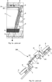
- Fig. 1b shows a cross section of a roof window 200 with fitted flashings, as known in the art.
- the roof construction comprises battens 7 for supporting the tiles 8.
- a window pane 201 is supported by a window sash 202.
- a window frame comprising a top frame member 203, a bottom frame member 204 and two side frame members (not shown) extending between the top frame member 203 and the bottom frame member 204 is supported by the roof construction.
- the window is sealed and drained by flashing parts substantially as described in the above, of which the first flashing portion 31 of the top flashing 3 is substantially parallel to the plane of the roof.
- the expression top flashing indicates that the first flashing portion 31 of the top flashing 3 is secured to the roof construction and the second flashing portion 32 is secured to an outer side of the top frame member 203.
- An upper portion of the roof window is provided with a top cladding 20 which is interconnected to the top flashing 3 by a fold on the second flashing portion 32 hooking over a flange on the top cladding.
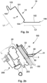
- Fig. 2a shows an embodiment of a top covering member 10 according to the invention.
- the top covering member 10 comprises an interior side 11 configured to face a roof penetrating structure when the top covering member is in a mounted state, and an exterior side 12 opposite the interior side and configured to face away from the roof penetrating structure in the mounted state.
- the top covering member 10 further comprises different portions each serving different functions, a first cover portion 101 having a length L1, a second cover portion 102 having a length L2, an attachment portion 103 and an adjustment portion 104.
- the attachment portion 103 comprises at least one interlocking engagement member 105, but currently it is considered advantageous that the attachment portion 103 comprises a plurality of interlocking engagement members, such as 2, 3, 5, 10 or 20, being evenly placed throughout the width of the attachment portion 103.
- the number of interlocking engagement members may depend on the width of the top covering member.
- Each interlocking engagement member 105 is configured to engage and interlock with a top frame member for fixing the top covering member 10 to the roof penetrating structure.
- the second cover portion 102 may comprise a bend 106 at the end of the second cover portion 102 to provide rigidity and provide a lip as will be described below.
- Fig. 2b shows an embodiment of a weather-proofing system 100 comprising the top covering member 10 of figure 2a installed on a top frame member of a roof penetrating structure corresponding to the top frame member 203 of Figs. 1a and 1b .
- the top flashing 3 comprises a first flashing portion 31 and a second flashing portion 32 extending substantially perpendicular to each other.
- the first flashing portion 31 extends longer upwards along the sloping roof than the top covering member 10.
- the second flashing portion 32 extends in a second direction substantially parallel with the outer side of the top frame member, here covering substantially the entire outer side of the top frame member.
- the top covering member 10 is mounted on top of the top flashing and a major portion, i.e. more than 50 %, of the top covering member 10 overlaps the top flashing 3.
- the first cover portion 101 extends higher than the flashing 3 in a direction perpendicular to the roof plane and a base section of the attachment portion 103 is perpendicular to the first cover portion, extending over an exterior side of the the top frame member 203 towards a top cladding 20 of the roof window 200.
- the first cover portion 101 runs substantially parallel with the outer side of the top frame member 203 and is formed in one with the attachment portion 103 at one end and with the adjustment portion 104 at an opposite end, the adjustment portion 104 in turn being formed in one with the second cover portion 102.
- the entire top covering member 10 is formed from a single sheet of metal, such as aluminium or copper, but it could also be made from a polymer.
- the adjustment portion 104 is located between the first cover portion 101 and second cover portion 102 and faces the second flashing portion 32.
- the adjustment portion 104 comprises an inwards bend, bending towards the the second flashing portion 32 and the top frame member 203 in the mounted state.
- the inwards bend enables at least partly closing a gap between the top covering member 10 and the second flashing portion 32 of the top flashing 3, such that in the mounted state a distance D1 between the adjustment portion 104 and the second flashing portion 32 is less than a distance D2 between the first cover portion and the second flashing portion 32.
- the distance D1 may be 10 mm, 5 mm, 3 mm, 2 mm, 1 mm or less.
- the distance D1 may advantageously be such that the adjustment portion abuts the second flashing portion 32.
- the distance may vary slightly during use, for example due to thermal expansion.
- the inwards bend may enable the first and second cover portions to be pivotable relative to each other to provide the top covering member 10 with adjustability, e.g. so it can be fitted and configured to various roof penetrating structures.
- a further advantage of the inwards bend is that it may provide sealing between the top covering member 10 and the top flashing 3, where there is normally the need to install a gasket or rubber strip to seal this space.
- a drain cavity 40 is present between the second cover portion 102 and the top flashing 3.
- the drain cavity 40 may provide a better drain by draining off any water not being drained by the drainage channel formed top covering member 10 and the top flashing 3 on the upper outer side of the second cover portion 102.
- Especially during heavy wind water may be turbulent, and by having the drain cavity some water can be drained above the top of top covering member 10 and while some water that enters the drain cavity 40 can be drained as a laminar flow through the drain cavity.
- the bend 106 at the end of the second cover portion 102 may be in contact with top flashing 3 when installed or when in use.
- the top covering member 10 may however be arranged with a gap between the second cover portion and the top flashing when installed and still provide good draining.
- a resilient force may be provided to the first cover portion 101 to minimize the gap.
- the bend 106 may further protect the top flashing 3 from being damaged when installing and using the top covering member, as a second cover portion without the bend may scratch the top flashing when it is adjusted to an given installation depth or height of the roof penetrating structure.
- top covering member 10 could be inserted in a recess in the top cladding 20 and that a barb or other interlocking member could be projecting outwards instead of inwards. Still further, a barb or other interlocking member could snap into an opening instead of snapping underneath a free edge.
- Fig. 4 shows an alternative embodiment of the interlocking engagement member 105.
- it is formed as a local depression in a sheet metal material from which the top covering member 10 is formed.
- the depression may snap in underneath a free edge of the top cladding member 20 in substantially the same way as the described with reference to Figs 3a-3c , but may be easier to release due to its rounded shape.
- the depression, as opposed to the barb will be visible to someone needing to remove the top covering member, making it easy to see where a tool should be inserted to release the top covering member from the top cladding member.
- the depression is comparatively easy to make and does not require additional material, and hence production costs will be low.
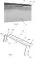
- Fig. 5 shows an embodiment of the top covering member 10.
- the top covering member comprises two arms 13.
- the arms 13 extend downwards and provide cover for the upper parts of the sides of the window frame when the top covering member 10 is mounted, overlapping with side covering members (not shown).
- the arms 13 also allows the attachment portion 103 of the top covering member to extend downwards along the sides of window frame to provide sealing and attachment of the top covering member with longitudinal ends of the top cladding 20 (not shown in Fig. 5 ).
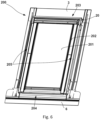
- the roof window is mountable in a sloped roof construction, the sloping roof window 200 comprises as described in the above top frame member 203, bottom frame member 204 and two side frame members 205 extending therebetween.
- the window 200 may further comprise all the standard elements known from the prior art, e.g. as those described above in relation to figure 1a and 1b .
- top covering member 20 has been shown only as being attached to a top cladding member, but it is to be understood that it could be attached to another element on a roof penetrating structure.
Landscapes
- Engineering & Computer Science (AREA)
- Architecture (AREA)
- Civil Engineering (AREA)
- Structural Engineering (AREA)
- Roof Covering Using Slabs Or Stiff Sheets (AREA)
Abstract
The top covering member (10) is intended to at least partly cover a top frame member of a roof penetrating structure mounted in a sloping roof and comprises an interior side (11) configured to face the roof penetrating structure when the top covering member is in a mounted state, and an exterior side (12) opposite the interior side and configured to face away from the roof penetrating structure in the mounted state. The top covering member (10) comprises a first cover portion (101), a second cover portion (102), an attachment portion (103) at the first cover portion (101) comprising an interlocking engagement member (105), and an adjustment portion (104) located between the first and second cover portion and enabling the first and second cover portion to pivot relative to each other. The interlocking engagement member (105) is configured to engage and interlock with the top frame member for fixing the top covering member (10) to the roof penetrating structure.

Description
- The present invention relates to a top covering member and a weather-proofing system for a roof penetrating structure, like a roof window or skylight. The invention furthermore relates to a sloping roof penetrating window.
- When installing roof penetrating structures, like roof windows, skylights or solar collectors, it is vital to ensure that the roof penetrating structure and its connection to the roof structure is watertight to not compromise the underlying roof constructions and building.
- This is done by covering the frame structures of the roof penetrating structure with covering material which overlaps cladding of the frame structures and flashing on the roof, thereby seeking to create a watertight seal between the roof penetrating structure and the roof.
- A problem related to present roof penetrating structures is that the installation depth in the roof structures and/or the height of the roof penetrating structure may not be standardized and hence differs from one structure to another. Consequently, adjustment or customization may be necessary. Another problem may arise when replacing existing roof penetrating structures, where an old structure is removed and a new structure with a new height and/or installation depth is installed. In case of replacement of the roof penetrating structure, part of the old flashing may remain and be reused while covering material may be replaced, and the two parts should be compatible and ensure a watertight joint.
- Another problem is associated with rain and other precipitation and the drainage of water. The drain design of a roof penetrating structure is critical to prevent wind and storm from forcing water through junctions or overlaps between flashings and covering members. The covering members should overlap the flashing at their junctions in order to prevent the water from entering. The overlapping also needs to be considered according to the inclination of the sloping roof to ensure that the water is drained correctly under the influence of gravity and wind. This is particularly the case at the top of a roof window, where water needs to either pass over the covering at the top and onto the roof penetrating structure or be led out to the sides. The top is here and in the following to be understood as the part located highest when seen in the direction of slope in the mounted state.
- Consequently, many factors need to be considered when designing coverings that perform well with various roof penetrating structures and various roof inclinations.
-
EP2192248 discloses an assembly with a top flashing and a top covering member comprising pivot means linking a first and second portion and providing a drain cavity between the first portion and the flashing when in use. While the solution alleviates some of the problems in the art there is a continued need for further developments to improve, mitigate or address the shortcomings of the prior art. - According to a first aspect this and further objects are achieved by provision of a top covering member for at least partly covering a top frame member of a roof penetrating structure mounted in a sloping roof, the top covering member comprising an interior side configured to face the roof penetrating structure when the top covering member is in a mounted state, and an exterior side opposite the interior side and configured to face away from the roof penetrating structure in the mounted state; said top covering member comprising a first cover portion; a second cover portion; an adjustment portion located between the first and second cover portions and enabling the first and second cover portions to pivot relative to each other; and an attachment portion at the first cover portion comprising an interlocking engagement member; where the interlocking engagement member is configured to engage and interlock with the top frame member for fixing the top covering member to the roof penetrating structure.
- Providing an attachment portion for fixing the top covering member to a roof penetrating structure by engagement and interlocking may enable installation of the top covering member to the roof penetrating structure without the use of tools. Thereby, a way of securing a correct and/or more precise installation of the top covering member is provided. This may aid in securing a watertight joint between the top covering member and a top frame member of a roof penetrating structure and/or a top flashing.
- A further advantage may be that the installation process is faster and/or easier.
- A further advantage may be that the top covering member allows for adjustment to fit different roof penetrating structures and/or various installation depths. This is advantageous when replacing old roof penetrating structures with new structures with different height and/or installation depth. The provided top covering member may also enable installation with existing top flashings.
- A further advantage may be that the top covering member allows for adjustment to secure a watertight joint between the top covering member and a top frame member of a roof penetrating structure and/or top flashing.
- The top frame member is here to be understood broadly as including not only a traditional load-bearing element, but also associated elements, such as an insulating element extending at the top frame member, for example forming part of an insulting frame surrounding a roof penetrating structure, or a part of an installation frame surrounding and supporting the roof penetrating structure.
- In the context of the disclosure it may be understood that engage or engagement is a snug connection between corresponding parts without requiring the parts being locked together, i.e. they may be easily separable.
- In the context of the disclosure it may be understood that interlock or interlocking is understood to encompass two parts being locked or fixed together to a degree which necessities active mechanical manipulation of one or both of the parts in order to achieve unlocking and separation. The interlocking is preferably reversible, i.e. one or both parts may undergo mechanical manipulation to achieve separation without any part being damaged.
- The combination of engagement and interlocking may be a click-on type of mechanical fixation between the top covering member and the roof penetrating structure, such as a mechanism of snap-locking, barb-locking, slide-locking, or the like. A depression in a sheet material may snap into an opening or underneath or over a free edge to establish an interlocking. A depression may have a rounded shape facilitating engagement and disengagement and/or may be advantageous in production as it does not require extra material and can be made with simple tools.
- The interlocking engagement member may engage and interlock with a corresponding portion of the top frame member, such as a recess or protrusion of the top frame member.
- Alternatively or additionally, the attachment portion may be configured to engage and interlock with a top cladding of the top frame member for fixing the top covering member to the roof penetrating structure. The interlocking engagement member may engage and interlock with a top cladding of the top frame member, e.g. with a corresponding portion, recess or protrusion of the top cladding.
- In some embodiments, the interlocking engagement member is protruding from the attachment portion, possibly being a deformation on a plate material. The interlocking engagement member may hook on to a top frame member or a top cladding to interlock the top covering member with a roof penetrating structure. A protrusion may be configured to engage and interlock with a corresponding recess or edge of a top frame member or a top cladding. The projection may snap or click onto or into the top frame member or the top cladding. For this purpose the interlocking engagement member, the attachment portion, the top frame member, and/or the top cladding or a part of one or more of them may be made from an elastic material.
- In some embodiments, the attachment portion comprises a plurality of interlocking engagement members each configured to engaged and interlock with the top frame member for fixing the top covering member to the roof penetrating structure. A plurality of interlocking engagement members may provide an improved interlocking of the top covering member and/or facilitate installation and subsequent removal of the top covering member by providing several relatively weak interlocking engagements rather than one strong interlocking engagement.
- The attachment portion may comprise a plurality of protrusions each configured to engaged and interlock with a corresponding recesses or an edge of a top frame member or top cladding for fixing the top covering member to a roof penetrating structure.
- The adjustment portion may provide an angle between the first cover portion and second cover portion of 20 to 70 degrees, preferably 30 to 60 degrees, and may provide the top covering member with adjustability, such as pivotability between the first and second cover portion.
- In some embodiments, the adjustment portion is formed as an inwards bend projecting towards the top frame member in the mounted state to at least partly close a gap between the top covering member and the top frame member such that in the mounted state a distance between the adjustment portion and the top frame member is less than a distance between the first cover portion and the top frame member.
- In some embodiments, the adjustment portion is configured to provide a distance of less than 10 mm between the adjustment portion and the top frame member or a top flashing located between the adjustment portion and the top frame member in the mounted state. Having distance of 10 mm or less between the adjustment portion and the top frame member or top flashing limits the size of the gap in which water may access the roof penetrating structure to provide a sealing.
- Alternatively or additionally, the adjustment portion may be configured to provide a distance between the adjustment portion and the top frame member or top flashing of less than 10 mm, 5 mm, 3 mm, 2 mm or 1 mm.
- The distance of the gap may be measure between the peak / top point of the inwards bend of the adjustment portion and the top frame member or top flashing.
- Alternatively or additionally, the distance of the gap may be measured to constitute the smallest distance or closest distance between the adjustment portion and the top frame member or top flashing.
- The inwards bend may provide a tight seal between the top covering member and a top frame member of a roof penetrating structure and/or a top flashing without the need for additional sealing material, such as a gasket or rubber strip.
- The inwards bend may induce a pressure gradient, i.e. a difference in pressure on opposite sides of the adjustment portion, for example forming a pressure relief chamber between the first cover portion and the top frame member. Hence the sealing does not necessarily need to be completely watertight in order to prevent water from accessing the roof penetrating structure.
- In some embodiments, a length of the second cover portion enables an end of the second cover portion opposite the adjustment portion to come into contact the sloping roof or a part of a top flashing extending in parallel with the direction of slope of the roof in the mounted state. By having a length of the second cover portion which enables the second cover portion to come into contact with the sloping roof or a flashing thereon, a further improved sealing roof penetrating structure may be provided. Additionally it may provide a more efficient way to draining water running down from the roofing material, such as tiles, above the roof penetrating structure.
- The first and second cover portion may each have a length, which is substantially equal to each other. Substantially equal being lengths within ±5 % of each other. Alternatively, the second cover portion may have a length which is longer than a length of the first cover portion.
- The length of the first and second cover portions may be measured from edge to edge of the portion, i.e. once a bend is met a new portion begins.
- In some embodiments, the second cover portion of the top covering member is configured for providing a drain cavity between a top flashing mounted on the sloping roof and the second cover portion of the top covering member in a mounted state in addition to a drainage channel formed on top of the top cover member and the top flashing. This may provide better draining.
- In some embodiments, a bend of the second cover portion provides a lip at an edge of the second cover portion opposite to the edge linked to the adjustment portion. Such a lip may protect a top flashing from being damaged when installing and using the top covering member, as the second cover portion without a lip may scratch the top flashing when it is adjusted to a given installation depth.
- The bend may be an outwards bend, i.e. in a direction away from the roof penetrating structure in the mounted state. The bend may be an inwards bend, i.e. in a direction towards the roof penetrating structure in the mounted state.
- In some embodiments, the top covering member further comprises two arms configured to extend along two sides of the roof penetrating structure when the top covering member is in its mounted state. The arms may provide sealing and attachment of the top covering member to side covering members.
- The attachment portion may extend along the arms to provide engagement and interlocking of the arms with a top side of the sides of the roof penetrating structure or a cladding thereon.
- According to a second aspect of the invention there is provided a weather-proofing system for a roof penetrating structure mounted in a sloping roof, the system comprising a top covering member according to the first aspect; a top flashing comprising a first flashing portion and a second flashing portion; where the first flashing portion is configured for extending in a first direction substantially parallel to direction of slope of the roof in a mounted state and the second flashing portion extends in a second direction substantially perpendicular to the first direction, thereby providing a substantially L-shaped top flashing; where the first cover portion of the top covering member extends substantially parallel with the second flashing portion in the mounted state; and where at least a major portion of the top covering member overlaps the top flashing in the mounted state.
- Provision of a top flashing together with the top covering member may provide a system with improved sealing properties.
- In the context of the disclosure a major portion is to be considered more than 50 % by length, or by surface area of the interior or exterior side.
- A distance between the adjustment portion of the top covering member and the second flashing portion of top flashing may be less than 10 mm when the system is in use.
- Alternatively or additionally, the adjustment portion of the top covering member may be in contact with the second flashing portion of top flashing when the system is in use.
- The second flashing portion of the top flashing may comprise a bend at the end of the second flashing portion furthest away from the first flashing portion of the top flashing, where the end of the second flashing portion is bending towards the top covering member, away from the roof penetrating structure in the mounted state.
- A space between the second cover portion of the top covering member and the top flashing may provide a drain cavity when the system is in use.
- The dimensions of the drain cavity formed between the top flashing and the second cover portion of the top covering member may first increase and next decrease, when following a path from the adjustment portion of the top covering member towards the end of the second cover portion of the top covering member.
- According to a third aspect of the invention there is provided a sloping roof penetrating window for mounting in a sloped roof construction, the window comprising a top frame member, a bottom frame member and two side frame members extending therebetween; and a top cladding attached to an exterior side of the top frame member facing away from the roof construction when the window is in a mounted state, and further comprising a top covering member according to the first aspect, where the interlocking engagement member of the top covering member engages and interlocks with the top cladding; and where the top covering member overlaps and covers an outer side of the top frame member being substantially perpendicular to the plane of the sloped roof structure when the sloping roof window is in the mounted state.
- Consequently, there is provided a sloping roof penetrating window comprising a top covering member that can potentially be installed without the use of tools. Thereby, securing correct and/or more precise installation of the top covering member to aid in securing a tight seal between the top covering member and a top frame member of sloping roof penetrating window.
- A feature described in relation to one of the aspects may also be incorporated in other aspects, and the advantage of the feature is applicable to all aspects in which it is incorporated. To undue repetition, embodiments and advantages described with reference to the first and second aspects have not be repeated.
- Other presently preferred embodiments and further advantages will be apparent from the subsequent detailed description and drawings.
- In the following examples and embodiments of the invention will be described with reference to the schematic drawings, in which
-
Fig. 1a is a perspective view of an example of the principle of water drain in a roof structure installation as known in the prior art. -
Fig. 1b shows a cross section of an example of an installed roof window as known in the prior art. -
Fig. 2a shows a cross section of an embodiment of a top covering member according to the invention. -
Fig. 2b shows a cross section of an embodiment of a weather-proofing system according to the invention. -
Fig. 3a-c each shows a partial cross section of an example of a locking mechanism between a top covering member and a top cladding according to the invention. -
Fig. 5 shows a perspective view of an embodiment of a top covering member according to the invention. -
Fig. 6 shows a perspective view of an embodiment of an installed sloping roof penetrating window with a top covering member according to the invention. - The disclosed embodiments will now be described more fully hereinafter with reference to the accompanying drawings, in which certain embodiments of the disclosed embodiments are shown. These disclosed embodiments may, however, be embodied in many different forms and should not be construed as limited to the embodiments set forth herein; rather, these embodiments are provided by way of example so that this disclosure will be thorough and complete, and will fully convey the scope of the disclosed embodiments to those skilled in the art. Like numbers refer to like elements throughout.
- Referring initially to
Fig. 1a , which illustrates an example of water draining in a roof window installation as is common practice in the art. The water is drained by flashing parts that form adrain path 2. An aperture 1 for a roof penetrating structure e.g. a roof window is present in a roofconstruction comprising battens 7 and roofing in the form oftiles 8. To seal the structure/window (not shown) flashingparts e.g. flashing part 3 overlaps flashing part 4, etc. in order to provide a seal. The flashingpart 3 present at the top of the aperture 1 constitutes atop flashing 3 comprising twoportions first flashing portion 31 is substantially parallel to the plane of the roof, and thesecond flashing portion 32 protrudes substantially perpendicular thereto. Thetop flashing 3 drains the water coming from the tiles above the roof penetrating structure and directs the water towards the sides of the aperture. Thetop flashing 3 comprises arm portions extending down along the sides of the aperture. Next, the flashing part 4 at the side, constituting a side flashing 4, drains the water to the flashing part 5 at the bottom, constituting a bottom flashing 5. The bottom flashing 5 comprises aflexible skirt 6 which can be deformed to fit thecorrugated tiles 8. The width and height of the roof penetrating structure/window relative to the roof plane has influence on the drain requirements of thetop flashing 3. It is common to use flashings of sheet metal, for instance aluminium, copper, steel or zinc. -
Fig. 1b shows a cross section of aroof window 200 with fitted flashings, as known in the art. As inFig. 1a , the roof construction comprisesbattens 7 for supporting thetiles 8. Awindow pane 201 is supported by awindow sash 202. - A window frame comprising a
top frame member 203, abottom frame member 204 and two side frame members (not shown) extending between thetop frame member 203 and thebottom frame member 204 is supported by the roof construction. The window is sealed and drained by flashing parts substantially as described in the above, of which thefirst flashing portion 31 of thetop flashing 3 is substantially parallel to the plane of the roof. Hereafter, the expression top flashing indicates that thefirst flashing portion 31 of thetop flashing 3 is secured to the roof construction and thesecond flashing portion 32 is secured to an outer side of thetop frame member 203.. An upper portion of the roof window is provided with atop cladding 20 which is interconnected to thetop flashing 3 by a fold on thesecond flashing portion 32 hooking over a flange on the top cladding. -
Fig. 2a shows an embodiment of atop covering member 10 according to the invention. Thetop covering member 10 comprises aninterior side 11 configured to face a roof penetrating structure when the top covering member is in a mounted state, and anexterior side 12 opposite the interior side and configured to face away from the roof penetrating structure in the mounted state. Thetop covering member 10 further comprises different portions each serving different functions, afirst cover portion 101 having a length L1, asecond cover portion 102 having a length L2, anattachment portion 103 and anadjustment portion 104. Theattachment portion 103 comprises at least one interlockingengagement member 105, but currently it is considered advantageous that theattachment portion 103 comprises a plurality of interlocking engagement members, such as 2, 3, 5, 10 or 20, being evenly placed throughout the width of theattachment portion 103. The number of interlocking engagement members may depend on the width of the top covering member. Each interlockingengagement member 105 is configured to engage and interlock with a top frame member for fixing thetop covering member 10 to the roof penetrating structure. Thesecond cover portion 102 may comprise abend 106 at the end of thesecond cover portion 102 to provide rigidity and provide a lip as will be described below. -
Fig. 2b shows an embodiment of a weather-proofingsystem 100 comprising thetop covering member 10 offigure 2a installed on a top frame member of a roof penetrating structure corresponding to thetop frame member 203 ofFigs. 1a and 1b . As infigs. 1a and 1b , thetop flashing 3 comprises afirst flashing portion 31 and asecond flashing portion 32 extending substantially perpendicular to each other. Thefirst flashing portion 31 extends longer upwards along the sloping roof than thetop covering member 10. Thesecond flashing portion 32 extends in a second direction substantially parallel with the outer side of the top frame member, here covering substantially the entire outer side of the top frame member. - The
top covering member 10 is mounted on top of the top flashing and a major portion, i.e. more than 50 %, of thetop covering member 10 overlaps thetop flashing 3. - The
first cover portion 101 extends higher than the flashing 3 in a direction perpendicular to the roof plane and a base section of theattachment portion 103 is perpendicular to the first cover portion, extending over an exterior side of the thetop frame member 203 towards atop cladding 20 of theroof window 200. Thefirst cover portion 101 runs substantially parallel with the outer side of thetop frame member 203 and is formed in one with theattachment portion 103 at one end and with theadjustment portion 104 at an opposite end, theadjustment portion 104 in turn being formed in one with thesecond cover portion 102. Here the entiretop covering member 10 is formed from a single sheet of metal, such as aluminium or copper, but it could also be made from a polymer. - The
adjustment portion 104 is located between thefirst cover portion 101 andsecond cover portion 102 and faces thesecond flashing portion 32. Theadjustment portion 104 comprises an inwards bend, bending towards the thesecond flashing portion 32 and thetop frame member 203 in the mounted state. The inwards bend enables at least partly closing a gap between thetop covering member 10 and thesecond flashing portion 32 of thetop flashing 3, such that in the mounted state a distance D1 between theadjustment portion 104 and thesecond flashing portion 32 is less than a distance D2 between the first cover portion and thesecond flashing portion 32. The distance D1 may be 10 mm, 5 mm, 3 mm, 2 mm, 1 mm or less. The distance D1 may advantageously be such that the adjustment portion abuts thesecond flashing portion 32. The distance may vary slightly during use, for example due to thermal expansion. - The inwards bend may enable the first and second cover portions to be pivotable relative to each other to provide the
top covering member 10 with adjustability, e.g. so it can be fitted and configured to various roof penetrating structures. - When installing the
top covering member 10 on roof penetrating structures having different height or installation depths the top covering member can be displaced in a direction perpendicular to the roof plane and theadjustment portion 104 then provides means for minimizing a gap between thesecond cover portion 102 and thefirst flashing portion 31. To adjust the size of the gap betweentop covering member 10 and thetop flashing 3 thesecond cover portion 102 is pivoted to provide anangle 50 between thefirst cover portion 101 andsecond cover portion 102 of 20 to 70 degrees, preferably 30 to 60 degrees. The pivotability andangle 50 between thefirst cover portion 101 andsecond cover portion 102 thus enables installation at various heights. - A further advantage of the inwards bend is that it may provide sealing between the
top covering member 10 and thetop flashing 3, where there is normally the need to install a gasket or rubber strip to seal this space. - In the mounted state a
drain cavity 40 is present between thesecond cover portion 102 and thetop flashing 3. Thedrain cavity 40 may provide a better drain by draining off any water not being drained by the drainage channel formedtop covering member 10 and thetop flashing 3 on the upper outer side of thesecond cover portion 102. Especially during heavy wind water may be turbulent, and by having the drain cavity some water can be drained above the top oftop covering member 10 and while some water that enters thedrain cavity 40 can be drained as a laminar flow through the drain cavity. - The
bend 106 at the end of thesecond cover portion 102 may be in contact withtop flashing 3 when installed or when in use. Thetop covering member 10 may however be arranged with a gap between the second cover portion and the top flashing when installed and still provide good draining. A resilient force may be provided to thefirst cover portion 101 to minimize the gap. Thebend 106 may further protect the top flashing 3 from being damaged when installing and using the top covering member, as a second cover portion without the bend may scratch the top flashing when it is adjusted to an given installation depth or height of the roof penetrating structure. -
Fig. 3a-3c illustrated an example of a interlocking between the top covering member offigure 2a and figure 2b and thetop cladding 20 according to the invention, showing only theattachment portion 103 and a part of the first cover portion and aprotrusion 21 at an end of thetop cladding 20. - In
Fig. 3a theattachment portion 103, which has the shape of an inverted U, is brought into close proximity of thetop cladding 20 such that arecess 107 of theattachment portion 103 aligns with theprotrusion 21 of the top cladding. Theattachment portion 103 is brought down over the protrusion of thetop cladding 20 for theattachment portion 103 to engage the top cladding. - The protrusion here also has the shape of an inverted U and it is slightly wider than the opening of the
recess 107. This means that theprotrusion 21 is compressed when inserted in the recess as shown inFig. 3b . It could, however, also be theleg 108 at the free edge of thetop covering member 10, which was forced aside while the protrusion maintained its shape, or both could deform at the same time. - It is also to be understood that a protrusion on the
top covering member 10 could be inserted in a recess in thetop cladding 20 and that a barb or other interlocking member could be projecting outwards instead of inwards. Still further, a barb or other interlocking member could snap into an opening instead of snapping underneath a free edge. These considerations applies to all embodiments. - The insertion is continued in the same direction until the protrusion of the
top cladding 20 is fully inserted into the recess of theattachment portion 103 as illustrated inFig. 3c . As the outer dimension of the U-shape of the protrusion matches the inner dimensions of the recess theprotrusion 21 springs back into its original shape when the engagement is complete thereby interlocking theattachment portion 103 to the top cladding for fixing thetop covering member 10 to thetop frame 203. The friction between the two U-shapes can be enough to achieve an interlocking, but in this embodiment a barb-like projection 105 at the free edge of thetop covering member 10 snaps in underneath the free edge of thetop cladding 20. If the interlocking is to be released, the barb-like projection 105 would have to be forced aside before lifting the top covering member off the top cladding. -
Fig. 4 shows an alternative embodiment of the interlockingengagement member 105. Instead of being barb-shaped as inFigs 3a-3c , it is formed as a local depression in a sheet metal material from which thetop covering member 10 is formed. The depression may snap in underneath a free edge of thetop cladding member 20 in substantially the same way as the described with reference toFigs 3a-3c , but may be easier to release due to its rounded shape. Furthermore, the depression, as opposed to the barb, will be visible to someone needing to remove the top covering member, making it easy to see where a tool should be inserted to release the top covering member from the top cladding member. Still further, the depression is comparatively easy to make and does not require additional material, and hence production costs will be low. -
Fig. 5 shows an embodiment of thetop covering member 10. The top covering member comprises twoarms 13. Thearms 13 extend downwards and provide cover for the upper parts of the sides of the window frame when thetop covering member 10 is mounted, overlapping with side covering members (not shown). Thearms 13 also allows theattachment portion 103 of the top covering member to extend downwards along the sides of window frame to provide sealing and attachment of the top covering member with longitudinal ends of the top cladding 20 (not shown inFig. 5 ). -
Fig. 6 shows a perspective view of an embodiment of an installed slopingroof penetrating window 200 comprising a covering and weather-proofing system according to the invention and described in relation to any ofFigs. 2 to 5 . - The roof window is mountable in a sloped roof construction, the sloping
roof window 200 comprises as described in the abovetop frame member 203,bottom frame member 204 and twoside frame members 205 extending therebetween. Thewindow 200 may further comprise all the standard elements known from the prior art, e.g. as those described above in relation tofigure 1a and 1b . - The
top cladding 20 of the roof window is in the embodiment shown attached to an exterior side of the top frame member facing away from the roof structure when the window is in a mounted state. - It will be understood that the embodiments described herein are merely exemplary and that variations and modifications of the teachings will still fall within the scope of this invention. For example the
second cover portion 102 may comprise grooves or corrugations to enable easier bending/adjustment. For example thesecond cover portion 102 may be made from a flexible material. For example thesecond cover portion 102 may be arc shaped. For example thesecond cover portion 102 may have any shape suitable for adjustment and forming a cavity. - Furthermore, some of the features of the examples of this invention may be used to advantage without the corresponding use of other features. As such, the foregoing description should be considered as merely illustrative of the principles, teachings, examples and exemplary embodiments of this invention, and not in limitation thereof.
- In the drawing, the
top covering member 20 has been shown only as being attached to a top cladding member, but it is to be understood that it could be attached to another element on a roof penetrating structure. -
- 1
- Aperture
- 2
- Drain path
- 3
- Flashing part / Top flashing
- 31
- First flashing portion
- 32
- Second flashing portion
- 4
- Flashing part / Side flashing
- 5
- Flashing part / Bottom flashing
- 6
- Flashing part / Flexible skirt
- 7
- Battens
- 8
- Tiles
- 10
- Top covering member
- 101
- First cover portion
- 102
- Second cover portion
- 103
- Attachment portion
- 104
- Adjustment portion
- 105
- Interlocking engagement member
- 106
- Bend at the end of the second cover portion
- 107
- Recess
- 11
- Interior side
- 12
- Exterior side
- 13
- Arms
- 20
- Top cladding
- 21
- Protrusion
- 40
- Drain cavity
- 50
- Angle
- 100
- Weather-proofing system
- 200
- Sloping roof penetrating window
- 201
- Window pane
- 202
- Window sash
- 203
- Top frame member
- 204
- Bottom frame mamber
- D1
- Distance between the adjustment portion and the top frame member
- D2
- Distance between the first cover portion and the top frame member
- L1
- Length of first cover portion
- L2
- Length of second cover portion
Claims (16)
- Top covering member (10) for at least partly covering a top frame member of a roof penetrating structure mounted in a sloping roof, the top covering member (10) comprising:an interior side (11) configured to face the roof penetrating structure when the top covering member is in a mounted state, and an exterior side (12) opposite the interior side and configured to face away from the roof penetrating structure in the mounted state;a first cover portion (101);a second cover portion (102);an attachment portion (103) at the first cover portion (101) comprising an interlocking engagement member (105); andan adjustment portion (104) located between the first and second cover portion and enabling the first and second cover portion to pivot relative to each other;characterised in thatthe interlocking engagement member (105) is configured to engage and interlock with the top frame member for fixing the top covering member (10) to the roof penetrating structure.
- Top covering member according to claim 1, where the adjustment portion (104) is formed as an inwards bend bending towards the top frame member in the mounted state, to at least partly close a gap between the top covering member and the top frame member such that in the mounted state a distance (D1) between the adjustment portion (104) and the top frame member is less than a distance (D2) between the first cover portion and the top frame member.
- Top covering member according to claim 1 or 2, where the adjustment portion (104) is configured to provide a distance of less than 10 mm between the adjustment portion (104) and the top frame member or a top flashing (3) located between the adjustment portion and top frame member, in the mounted state.
- Top covering member according to claim 3, where the adjustment portion (104) is configured to abutting the top frame member or top flashing, in the mounted state.
- Top covering member according any one of claim 1 to 4, where the interlocking engagement member is protruding from the attachment portion, possibly being a deformation on a plate material.
- Top covering member according to any one of claim 1 to 5, where the attachment portion (103) comprises a plurality of interlocking engagement members (105) each configured to engaged and interlock with the top frame member for fixing the top covering member to the roof penetrating structure.
- Top covering member according to any one of the previous claims, where in the mounted state a length (L2) of the second cover portion (102) enables an end of the second cover portion opposite the adjustment portion to come into contact the sloping roof or a top flashing (3) mounted on the sloping roof.
- Top covering member according to any one of the previous claims, where the second cover portion (102) in a mounted state provides a drain cavity (40) between the second cover portion and a top flashing 3 mounted on the sloping roof.
- Weather-proofing system (100) for a roof penetrating structure mounted in a sloping roof, the system comprising:- a top covering member (10) according to any one of claim 1 to 8;- a top flashing (3) comprising a first flashing portion (31) and a second flashing portion (32);where the first flashing portion (31) is configured for extending in a first direction substantially parallel to the direction of slope of the roof in a mounted state and the second flashing portion (32) extends in a second direction substantially perpendicular to the first direction, thereby providing a substantially L-shaped top flashing;where the first cover portion (101) of the top covering member (10) extends substantially parallel with the second flashing portion (32) in the mounted state; and where at least a major portion of the top covering member (10) overlaps the top flashing in the mounted state.
- Weather-proofing system (100) according to claim 9, where a distance between the adjustment portion (103) of the top covering member and the second flashing portion (32) is less than 10 mm in the mounted state.
- Weather-proofing system (100) according to claim 9, where the adjustment portion (104) of the top covering member is in contact with the second flashing portion (32) in the mounted state.
- Weather-proofing system (100) according to any one of claim 9 to 11, where the second flashing portion (32) comprises a bend at the end of the second flashing portion (32) furthers away from the first flashing portion (31); and where the bend of the second flashing portion (32) is bending towards the first cover portion (101).
- Weather-proofing system (100) according to any one of claim 9 to 12, where a space between the second cover portion (102) and the top flashing provides a drain cavity (40) in the mounted state.
- Weather-proofing system according to claim 13, where the drain cavity (40) span formed between the top flashing and the second cover portion (102) first increases and next decreases, when following a path from the adjustment portion (103) of the top covering member (10) towards the end (105) of the second cover portion of the top covering member (10).
- Weather-proofing system for a roof penetrating structure mounted in a sloping roof, the system comprising:- a top covering member (10) according to any one of claim 1 to 8; and- a top cladding (20);said top covering member and said top cladding having interlocking engagement members configured for interlocking engagement with each other.
- Sloping roof penetrating window (200) for mounting in a sloped roof construction, the window (200) comprising a top frame member (203), a bottom frame member (204) and two side frame members (205) extending therebetween; and a top cladding (20) attached to an exterior side of the top frame member facing away from the roof construction when the window is in a mounted state, and further comprising a top covering member (10) according to any one of claim 1 to 8, where the interlocking engagement member (105) of the top covering member (10) engages and interlocks with the top cladding (20); and where the top covering member (10) overlap and covers an outer side of the top frame member being substantially perpendicular to the plane of the sloped roof structure when the sloping roof window is in the mounted state.
Applications Claiming Priority (1)
| Application Number | Priority Date | Filing Date | Title |
|---|---|---|---|
| DKPA202370534 | 2023-10-13 |
Publications (1)
| Publication Number | Publication Date |
|---|---|
| EP4538476A1 true EP4538476A1 (en) | 2025-04-16 |
Family
ID=93117453
Family Applications (1)
| Application Number | Title | Priority Date | Filing Date |
|---|---|---|---|
| EP24206153.9A Pending EP4538476A1 (en) | 2023-10-13 | 2024-10-11 | Top covering member, a weather-proofing system for a roof penetrating structure, and a sloping roof penetrating window |
Country Status (1)
| Country | Link |
|---|---|
| EP (1) | EP4538476A1 (en) |
Citations (5)
| Publication number | Priority date | Publication date | Assignee | Title |
|---|---|---|---|---|
| EP0756659B1 (en) * | 1994-04-18 | 1999-11-03 | VELUX Industri A/S | A flashing for roof elements |
| EP0760044B1 (en) * | 1994-04-15 | 2000-11-15 | Monarflex A/S | A building element for sealing a hole of a foil of an underroof |
| EP2192248A1 (en) | 2008-11-26 | 2010-06-02 | VKR Holding A/S | Roof component flashing, a flashing system and a method of flashing |
| WO2023186248A1 (en) * | 2022-03-31 | 2023-10-05 | Vkr Holding A/S | A roof window with a diverter rail |
| EP4023835B1 (en) * | 2020-12-30 | 2023-10-11 | VKR Holding A/S | A roof window system with a cover assembly |
-
2024
- 2024-10-11 EP EP24206153.9A patent/EP4538476A1/en active Pending
Patent Citations (6)
| Publication number | Priority date | Publication date | Assignee | Title |
|---|---|---|---|---|
| EP0760044B1 (en) * | 1994-04-15 | 2000-11-15 | Monarflex A/S | A building element for sealing a hole of a foil of an underroof |
| EP0756659B1 (en) * | 1994-04-18 | 1999-11-03 | VELUX Industri A/S | A flashing for roof elements |
| EP2192248A1 (en) | 2008-11-26 | 2010-06-02 | VKR Holding A/S | Roof component flashing, a flashing system and a method of flashing |
| EP2192248B1 (en) * | 2008-11-26 | 2015-07-15 | VKR Holding A/S | Roof component flashing, a flashing system and a method of flashing |
| EP4023835B1 (en) * | 2020-12-30 | 2023-10-11 | VKR Holding A/S | A roof window system with a cover assembly |
| WO2023186248A1 (en) * | 2022-03-31 | 2023-10-05 | Vkr Holding A/S | A roof window with a diverter rail |
Similar Documents
| Publication | Publication Date | Title |
|---|---|---|
| KR101355881B1 (en) | Fixing structure of solar battery module, frame for the solar battery module, and fixing member | |
| EP2192248B1 (en) | Roof component flashing, a flashing system and a method of flashing | |
| EP3966401B1 (en) | Flashing assembly for a roof penetrating structure and a method for manufacturing a flashing assembly | |
| EP3971363B1 (en) | A roof window with an improved pane element, and a method of manufacturing a roof window | |
| WO2007034171A1 (en) | Roof flashing connections | |
| EP3404162B1 (en) | A roof window installed in an inclined roof structure with a flashing assembly and a method for weather proofing a roof window | |
| US12421728B2 (en) | Roof window, a kit with a covering assembly, and a method for mounting a roof window | |
| CN209891586U (en) | Waterproof external member | |
| CN112922218B (en) | Sealing gasket between waterproof members, roof window waterproof device and gap sealing method | |
| SK282791B6 (en) | A flashing for roof elements | |
| US9187905B2 (en) | Roof or window panel to metal roofing or siding interface securement system | |
| JP2025511088A (en) | Roof window with diverter rail | |
| EP1567732B1 (en) | A flashing device and a method of installing a roof penetrating structure by means of the flashing device | |
| EP1297230B1 (en) | Flashing assembly with flexible flange members | |
| CN219261554U (en) | Install elevator vestibule canopy watertight fittings additional and install elevator vestibule additional | |
| US20250188746A1 (en) | Cover assembly and a method for interconnecting cover members | |
| JP4078607B2 (en) | Eaves structure of roof with metal tiles | |
| EP4214376A1 (en) | Coating cover for roofs of civil or industrial buildings | |
| JPH04130634U (en) | Drainage structure for lighting windows | |
| JPH04110830U (en) | sky window |
Legal Events
| Date | Code | Title | Description |
|---|---|---|---|
| PUAI | Public reference made under article 153(3) epc to a published international application that has entered the european phase |
Free format text: ORIGINAL CODE: 0009012 |
|
| STAA | Information on the status of an ep patent application or granted ep patent |
Free format text: STATUS: THE APPLICATION HAS BEEN PUBLISHED |
|
| AK | Designated contracting states |
Kind code of ref document: A1 Designated state(s): AL AT BE BG CH CY CZ DE DK EE ES FI FR GB GR HR HU IE IS IT LI LT LU LV MC ME MK MT NL NO PL PT RO RS SE SI SK SM TR |
|
| STAA | Information on the status of an ep patent application or granted ep patent |
Free format text: STATUS: REQUEST FOR EXAMINATION WAS MADE |
|
| 17P | Request for examination filed |
Effective date: 20250825 |