TECHNICAL FIELD
-
The subject disclosure relates to gullies for receiving storm water, usually collected from street surfaces, and discharging the storm water through an outlet in a rainwater sewer system.
BACKGROUND ART
-
Gulley's as described above are well known for collecting rain water or storm water in streets, sidewalks, gutters etc. and generally comprise a gulley pot, e.g. a plastic, cast-iron or concrete receptacle buried in the ground and comprising a bottom wall and a number of side walls. In a side wall of the gulley pot an outlet is positioned which is coupled to a sewer system. Water received in the gulley pot exits via the outlet to the sewer system. The drain is generally offset from the bottom wall. In the volume between the bottom wall of the gulley pot and the underside of the outlet, water and pollution (refuse, debris, leaves, sand, oil, etc....) can accumulate. A baffle extending to below the underside of the outlet serves as an odour trap and it may prevent pollution floating on the water from entering the sewer system.
-
EP3674493A1 discloses a gulley comprising a gulley pot, an outlet in a side wall of the gulley pot. The outlet is configured to couple the gulley to a sewer system and has an underside defining a normal outflow level L
norm. The gulley pot further comprises drainage outlets having an underside defining an additional outflow level L
drain. The drainage outlets enable the gulley to drain received liquid first to the ground around the gulley when the liquid level exceeds the level L
drain and only to release liquid to the sewer system when the liquid level exceeds the level L
norm.
-
CN206205290U discloses a roof rainwater collecting and processing system. The system comprises a rainwater seepage well with an inlet pipe, infiltration pipe and an outlet pipe. The infiltration pipe extends radially outward. A gravel layer surrounds the infiltration pipe. The bottom of the seepage well is covered with gravel and another gravel layer below the gravel forming the bottom of the seepage well. After two layer filtering the water enters the ground to replenish groundwater.
-
US10968616 discloses a drainage system for removing groundwater from underneath a water impervious surface including a first housing located below grade having a continuous sidewall, a floor, an open top extending to or through the surface through which stormwater collecting on the surface may enter into the housing, an outlet extending through the sidewall immediately adjacent to the floor and an inlet through the sidewall. A locking ring is fixed within the inlet, and a drain wick is coupled to the locking ring, the drain wick being configured for collecting groundwater underneath the surface and directing the groundwater through the inlet and into the housing. The drain wick includes a pipe having and plurality of radial openings, a perforated first end cap, a second end including screen and a locking nut configured for coupling to the locking ring and a filter bag located between the screen and end cap.
-
JP2005213917A discloses a water-permeable side ditch that can permeate only water and supply rainwater to neighbouring land. The side wall sections on both sides or on one side are formed of non-permeable concrete and permeable concrete. The permeable concrete sections are longitudinally spaced on the lower side of the side wall sections, and wherein the non-permeable concrete sections are other sections. In addition, the permeable gutters have a bottom section between both sidewall sections. Sidewall sections are made of permeable concrete and the bottom section is made of non-permeable concrete.
SUMMARY OF INVENTION
-
It is an object of the present technology to provide a gulley with increased storage capacity for draining liquid to the ground around the gulley without increasing the outer dimensions of the gulley and only diverting storm water to the sewer system when the liquid level reaches the outlet opening.
-
According to an aspect of the subject technology, this object is achieved by a gulley having the features of claim 1. Advantageous embodiments and further ways of carrying out the present technology may be attained by the measures mentioned in the dependent claims.
-
A gulley according to the subject technology comprises gulley comprising a gulley pot having a bottom and a sidewall provided with an outlet for discharging liquid in the gulley pot to drain piping. The bottom is a tile-like portion of concrete. The sidewall is a tube-like portion of components which form a rigid wall made of liquid-permeable material. Each of the tube-like portion and tile-like portion has a contact surface that connects the portions together. The tile-like portion has a crushing strength which is higher than the crushing strength of the tube-like portion.
-
The concept of the present technology is based on the knowledge that gulley's, such as a street catch basin and sidewalk catch basin, need to be regularly cleaned using a vacuum truck. The vacuum truck is equipped with a robotic arm consisting of a suction tube that is moved up and down in the gulley by a control system to suction out the collected debris in the gulley. During this process, the suction tube impacts the bottom of the gulley several times forcefully. It has been observed that liquid permeable or porous material is not resistant to these impacts and can quickly become damaged. By constructing the bottom of the gulley with a material that has a higher compressive strength than the material of the liquid permeable walls, the gulley is less prone to damage and requires less frequent replacement. With a tile-shaped bottom part and liquid permeable walls extending to the top surface of the tile shaped bottom part, all the water in the catch basin of the gulley can infiltrate into the ground surrounding the catch basin. This results in a gulley with a larger water storage capacity before the water from a heavy rain is directed to a stormwater sewer system than conventional gulley's while maintaining a comparable lifespan.
-
In an embodiment, the contact surface of tile-like portion declines from the inner side to the outer side of the gulley pot. This feature allows the water in the catch basin to drain down to the bottom of the catch basin, making nearly the entire water storage capacity available during a before water is discharged into the stormwater sewer during a rain event.
-
In a further embodiment, the contact surfaces are stepped. This feature ensures that the contact surface between the two sections is increased. This enhances the bond between the two sections.
-
In an embodiment, the tile-like portion comprises a recess in the centre of its upper surface. This feature allows for easier suction of a catch basin by a suction tube of a vacuum truck because the contents of the catch basin collect in the recess in the center of the bottom.
-
In a further embodiment, the recess is bowl-shaped. This shape ensures that the debris can be suctioned more effectively from the recess.
-
In an embodiment, the recess comprises a trapezium shaped cross section. This shape ensures that the recess is wider at the top, allowing the suction tube easier access to the recess and guiding it toward the center of the recess with further downward movement.
-
In an embodiment, the recess has a top edge which at least partially abuts an inner side of the tube-like portion. This causes the debris to flow from the side walls to the center of the bottom of the recess, resulting in less debris remaining after suctioning with a suction tube.
-
In an embodiment, the contact surface of the tile-like portion and the contact surface of the tube-like portion form matching profiles. The complementary profiles allow the gulley pot to be made from two pieces that can be securely bonded together with adhesive.
-
In an embodiment, the contact surface of the tube-like portion is located at a proximal end of the tube-like portion, and a distal end of the tube-like portion comprises a coupling structure for placing an inlet part on the distal end such that lateral movement is prevented. This feature allows for providing a universal catch basin onto which multiple types of inlet pieces can be placed. As a result, the catch basin can be used for multiple applications.
-
In an embodiment, the tube-like portion is made of liquid-permeable concrete. By using porous concrete, a gulley can be created that resembles existing catch basins in terms of appearance and dimensions.
-
In an embodiment, the tube-like portion and tile-like portion are connected to each other by means of an adhesive. This embodiment allows for creating a catch basin from two separate parts manufactured through different processes.
-
In an embodiment, the tube-like portion is obtained by pouring a concrete mixture of uncured concrete suitable for obtaining liquid-permeable concrete into a mould positioned on the tile-like portion, wherein during curing of the concrete, the tube-like part becomes connected to the tile-like portion. By pouring the walls on the outer edge of the tile-like portion, there is no need to glue the portions together in a separate production step. This allows for cost savings.
-
In an embodiment, the tile-like portion is made from earth-moist concrete. This feature provides a bottom known to be resistant to the forces exerted by a suction tube on the bottom of a gulley.
-
In an embodiment, the tile-like portion and/or tube-like portion are made from a concrete mixture comprising vegetal fibrous pieces. This feature allows for providing a lighter gulley with the desired strength. Additionally, it reduces the carbon footprint of the gulley as it stores CO2 in the form of plant particles in the concrete. In a further embodiment, said fibrous pieces have a width ranging from 0 to 5 mm width and a length ranging from 5 to 40 mm. The length of the fibers in the plant particles strengthens the concrete in the direction of the fibers.
BRIEF DESCRIPTION OF THE DRAWINGS
-
These and other aspects, properties and advantages will be explained hereinafter based on the following description with reference to the drawings, wherein like reference numerals denote like or comparable parts, and in which:
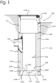
- Fig. 1 shows schematically a sectional view of a first embodiment of a gulley;
- Fig. 2 shows schematically another sectional view of the first embodiment;
- Fig. 3 shows schematically a sectional view along III-III in Fig. 2;
- Fig. 4 shows schematically a sectional view of a second embodiment of a gulley;
- Fig. 5 shows schematically another sectional view of the second embodiment; and,
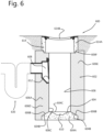
- Fig. 6 shows schematically a sectional view of a third embodiment of a gulley.
DESCRIPTION OF EMBODIMENTS
-
It is noted that the drawings are schematic, not necessarily to scale and that details that are not required for understanding the present invention may have been omitted. The terms "upward", "downward", "below", "above", and the like relate to the embodiments as oriented in the drawings, unless otherwise specified or functionally required. Further, elements that are at least substantially identical or that perform an at least substantially identical function are denoted by the same numeral.
-
Figs. 1, 2 and 3 illustrate a gulley 100 comprising a gulley pot 102 and an inlet part 114 positioned on the gulley pot 102. The inlet part 114 comprises a grating 114A and a removable cover 114B, both mounted on a support component 114A. The inlet part is configured for passing stormwater and associated pollution from streets, sidewalks, and gutters etc. into an interior volume of the gulley pot, where it collects after passing through the grate 114C. The grating 114C and removable cover 114B can be made of cast iron or any other suitable material. The support component 114A can be made of concrete, such as earth-moist concrete, or any other suitable material.
-
The interior volume of the gulley pot has a bottom 104 and an encompassing sidewall 106. The sidewall is provided with an outlet 108. The outlet 108 is configured for connecting to a drain piping of e.g. a storm water drainage system (not shown) and for discharging liquid in the gulley pot to the drain piping. The outlet 108 comprises a baffle assembly configured to prevent any floating pollutants entering the sewer system.
-
The bottom 104 is formed by a tile-like portion 104A of concrete and the sidewall 106 is a tube-like portion 106A forming a rigid liquid-permeable wall. The tube-like portion has a contact surface 106B and the tile-like portion has a contact surface 104B that joins the portions together. Preferably, the contact surface 104B of the tile-like portion 104A and the contact surface 106B of the tube-like portion 106A have mating profiles.
-
According to the subject technology the tile-like portion has a crushing strength which is higher than the crushing strength of the tube-like portion. In an advantageous embodiment, the tile is made of earth-moist concrete. However, any type of concrete with a compressive strength that can withstand the impact of the suction pipe of a vacuum truck can be used. Other materials the can withstand the impact of the suction pipe may be used.
-
The tube-like portion 106A is made of a liquid permeable material. In an advantageous embodiment, the tube-like portion is made of liquid-permeable concrete.
-
The tube-like portion and the tile-like portion can produced independently as separate components that are subsequently joined together using an adhesive to assemble the gulley pot.
-
In an alternative manufacturing process, the tile-like portion is produced first and subsequently the tube-like portion is obtained by pouring a concrete mixture of uncured concrete suitable for obtaining liquid-permeable into a mould positioned on the tile-like portion, wherein during curing of the concrete, the tube-like part becomes connected to the tile-like portion.
-
In an alternative production process, the tile-like part is first produced. Subsequently, a mould is placed on the tile-like portion, and a concrete mixture suitable for obtaining a liquid-permeable concrete is poured into the mould. During the curing of the concrete, the tube-like liquid-permeable portion is formed and simultaneously connected to the tile-like part on the surface area where the tile-like part is in contact with the not-yet-cured concrete mixture.
-
According to the subject technology, the tube-like portion of liquid-permeable material forming the sidewall of the interior volume of the gulley pot extends to the top-surface of the tile-like portion 104A. Furthermore, the contact surface 104B of tile-like portion slopes gradually from the inner side to the outer side of the gulley pot. This allows almost all the water in the gulley pot to infiltrate into the ground surrounding the gulley pot and the water level to drop to the top of the tile-like portion. In the first embodiment, contact surfaces are stepped.
-
The tile-like portion 104 comprises a recess 110 in the centre of its upper surface 104C that forms the bottom 104 of the interior space of the gulley pot. The dimensions of the recess depend on the dimensions of the suction tube used to sucked dirt from the gulley pot. The dimensions should be such that the suction pipe can reach the bottom of the recess. When cleaning the gully pot, dirt and water from the higher areas of the tile will flow into the recess and then be sucked away by the suction pipe. The recess comprises a trapezium shaped cross section.
-
The contact surface 106B of the tube-like portion being in contact with the tile-like portion is located at a proximal end 106D of the tube-like portion 106A. A distal end 106E of the tube-like portion comprises a coupling structure 106F for placing the inlet part 114 on the distal end such that lateral movement is prevented. The coupling structure 106F is formed by a narrow rim on top of the distal end.
-
Fig. 3 illustrates schematically a sectional view along III-III in Fig. 2. The dashed lines halfway up the walls of the gully pot indicate the step in the contact surface of the tile-like portion.
-
Figs 4 and 5 illustrate a second embodiment of a gulley pot. In this embodiment the recess has a top edge 410A which at least partially abuts the inner side 406C of the tube-like portion. If the recess is circular, then the upper edge will only partially contact the inside. If the recess is rectangular, then the upper edge 410A can abut against the inside wall of the gulley pot along its entire length. It should be noted, that the recess can also be bowl-shaped.
-
Fig. 6 illustrates a third embodiment of a gulley pot 602. In this embodiment, the wall formed by the tube-like portion 606A is much thicker than in the other embodiments. By making the wall thicker, the space to store water in the sump is also increased due to the voids in the water-permeable wall. Another difference is the profile of the contact surfaces 604B, 606B. The contact surface 604B of the tile-like portion 604A is now a sloping plane towards the outer edge of the tile instead of step-like. Furthermore, the water-permeable material from the tube-like portion extends along the side of the tile-like portion to the bottom of the gulley. This allows water to infiltrate directly into the ground directly below the gulley pot. On the third embodiment of a gulley pot 602 another type of inlet part 614 is positioned on the gulley pot to form a road gulley.
-
It should be noted that the device 612 installed in the outlet 608 is typically used as an odour trap and also as a debris catcher for debris floating on the water. Since the water level in the gulley will quickly decrease after a rainfall, the device installed in the outlet will no longer function as an odour trap. An odour trap function can be easily added by attaching piping 630 to the outlet forming a P-trap.
-
The concrete mixture for producing the tile-like portion and tube-like portion can comprises vegetal fibrous pieces, wherein the fibrous pieces have a width ranging from 0 - 5 mm and a length ranging from 5 to 40 mm.
NL2021223 discloses a method for producing concrete products based on vegetal aggregate, a binding agent, sand, gravel and water. By incorporating plant material into the concrete, a lighter concrete with similar strength is achieved. Additionally, CO2 is stored in the concrete product.
-
It is contemplated that alternatives, modifications, permutations and equivalents thereof will become apparent to those skilled in the art upon reading the specification and upon study of the drawings. The invention is not limited to the illustrated embodiments. Changes can be made without departing from the scope of the appended claims.