EP4538406A1 - Austenitic stainless alloy material - Google Patents
Austenitic stainless alloy material Download PDFInfo
- Publication number
- EP4538406A1 EP4538406A1 EP23819831.1A EP23819831A EP4538406A1 EP 4538406 A1 EP4538406 A1 EP 4538406A1 EP 23819831 A EP23819831 A EP 23819831A EP 4538406 A1 EP4538406 A1 EP 4538406A1
- Authority
- EP
- European Patent Office
- Prior art keywords
- alloy material
- content
- austenitic stainless
- less
- further preferably
- Prior art date
- Legal status (The legal status is an assumption and is not a legal conclusion. Google has not performed a legal analysis and makes no representation as to the accuracy of the status listed.)
- Pending
Links
Images
Classifications
-
- C—CHEMISTRY; METALLURGY
- C22—METALLURGY; FERROUS OR NON-FERROUS ALLOYS; TREATMENT OF ALLOYS OR NON-FERROUS METALS
- C22C—ALLOYS
- C22C38/00—Ferrous alloys, e.g. steel alloys
- C22C38/18—Ferrous alloys, e.g. steel alloys containing chromium
- C22C38/40—Ferrous alloys, e.g. steel alloys containing chromium with nickel
- C22C38/58—Ferrous alloys, e.g. steel alloys containing chromium with nickel with more than 1.5% by weight of manganese
-
- C—CHEMISTRY; METALLURGY
- C22—METALLURGY; FERROUS OR NON-FERROUS ALLOYS; TREATMENT OF ALLOYS OR NON-FERROUS METALS
- C22C—ALLOYS
- C22C38/00—Ferrous alloys, e.g. steel alloys
- C22C38/18—Ferrous alloys, e.g. steel alloys containing chromium
- C22C38/40—Ferrous alloys, e.g. steel alloys containing chromium with nickel
- C22C38/54—Ferrous alloys, e.g. steel alloys containing chromium with nickel with boron
-
- B—PERFORMING OPERATIONS; TRANSPORTING
- B21—MECHANICAL METAL-WORKING WITHOUT ESSENTIALLY REMOVING MATERIAL; PUNCHING METAL
- B21C—MANUFACTURE OF METAL SHEETS, WIRE, RODS, TUBES, PROFILES OR LIKE SEMI-MANUFACTURED PRODUCTS OTHERWISE THAN BY ROLLING; AUXILIARY OPERATIONS USED IN CONNECTION WITH METAL-WORKING WITHOUT ESSENTIALLY REMOVING MATERIAL
- B21C23/00—Extruding metal; Impact extrusion
- B21C23/02—Making uncoated products
- B21C23/04—Making uncoated products by direct extrusion
- B21C23/08—Making wire, rods or tubes
- B21C23/085—Making tubes
-
- C—CHEMISTRY; METALLURGY
- C21—METALLURGY OF IRON
- C21D—MODIFYING THE PHYSICAL STRUCTURE OF FERROUS METALS; GENERAL DEVICES FOR HEAT TREATMENT OF FERROUS OR NON-FERROUS METALS OR ALLOYS; MAKING METAL MALLEABLE, e.g. BY DECARBURISATION OR TEMPERING
- C21D1/00—General methods or devices for heat treatment, e.g. annealing, hardening, quenching or tempering
- C21D1/18—Hardening; Quenching with or without subsequent tempering
-
- C—CHEMISTRY; METALLURGY
- C21—METALLURGY OF IRON
- C21D—MODIFYING THE PHYSICAL STRUCTURE OF FERROUS METALS; GENERAL DEVICES FOR HEAT TREATMENT OF FERROUS OR NON-FERROUS METALS OR ALLOYS; MAKING METAL MALLEABLE, e.g. BY DECARBURISATION OR TEMPERING
- C21D1/00—General methods or devices for heat treatment, e.g. annealing, hardening, quenching or tempering
- C21D1/56—General methods or devices for heat treatment, e.g. annealing, hardening, quenching or tempering characterised by the quenching agents
- C21D1/58—Oils
-
- C—CHEMISTRY; METALLURGY
- C21—METALLURGY OF IRON
- C21D—MODIFYING THE PHYSICAL STRUCTURE OF FERROUS METALS; GENERAL DEVICES FOR HEAT TREATMENT OF FERROUS OR NON-FERROUS METALS OR ALLOYS; MAKING METAL MALLEABLE, e.g. BY DECARBURISATION OR TEMPERING
- C21D1/00—General methods or devices for heat treatment, e.g. annealing, hardening, quenching or tempering
- C21D1/56—General methods or devices for heat treatment, e.g. annealing, hardening, quenching or tempering characterised by the quenching agents
- C21D1/60—Aqueous agents
-
- C—CHEMISTRY; METALLURGY
- C21—METALLURGY OF IRON
- C21D—MODIFYING THE PHYSICAL STRUCTURE OF FERROUS METALS; GENERAL DEVICES FOR HEAT TREATMENT OF FERROUS OR NON-FERROUS METALS OR ALLOYS; MAKING METAL MALLEABLE, e.g. BY DECARBURISATION OR TEMPERING
- C21D6/00—Heat treatment of ferrous alloys
- C21D6/004—Heat treatment of ferrous alloys containing Cr and Ni
-
- C—CHEMISTRY; METALLURGY
- C21—METALLURGY OF IRON
- C21D—MODIFYING THE PHYSICAL STRUCTURE OF FERROUS METALS; GENERAL DEVICES FOR HEAT TREATMENT OF FERROUS OR NON-FERROUS METALS OR ALLOYS; MAKING METAL MALLEABLE, e.g. BY DECARBURISATION OR TEMPERING
- C21D6/00—Heat treatment of ferrous alloys
- C21D6/02—Hardening by precipitation
-
- C—CHEMISTRY; METALLURGY
- C21—METALLURGY OF IRON
- C21D—MODIFYING THE PHYSICAL STRUCTURE OF FERROUS METALS; GENERAL DEVICES FOR HEAT TREATMENT OF FERROUS OR NON-FERROUS METALS OR ALLOYS; MAKING METAL MALLEABLE, e.g. BY DECARBURISATION OR TEMPERING
- C21D8/00—Modifying the physical properties of ferrous metals or ferrous alloys by deformation combined with, or followed by, heat treatment
-
- C—CHEMISTRY; METALLURGY
- C21—METALLURGY OF IRON
- C21D—MODIFYING THE PHYSICAL STRUCTURE OF FERROUS METALS; GENERAL DEVICES FOR HEAT TREATMENT OF FERROUS OR NON-FERROUS METALS OR ALLOYS; MAKING METAL MALLEABLE, e.g. BY DECARBURISATION OR TEMPERING
- C21D8/00—Modifying the physical properties of ferrous metals or ferrous alloys by deformation combined with, or followed by, heat treatment
- C21D8/02—Modifying the physical properties of ferrous metals or ferrous alloys by deformation combined with, or followed by, heat treatment during manufacturing of plates or strips
- C21D8/0221—Modifying the physical properties of ferrous metals or ferrous alloys by deformation combined with, or followed by, heat treatment during manufacturing of plates or strips characterised by the working steps
- C21D8/0226—Hot rolling
-
- C—CHEMISTRY; METALLURGY
- C21—METALLURGY OF IRON
- C21D—MODIFYING THE PHYSICAL STRUCTURE OF FERROUS METALS; GENERAL DEVICES FOR HEAT TREATMENT OF FERROUS OR NON-FERROUS METALS OR ALLOYS; MAKING METAL MALLEABLE, e.g. BY DECARBURISATION OR TEMPERING
- C21D8/00—Modifying the physical properties of ferrous metals or ferrous alloys by deformation combined with, or followed by, heat treatment
- C21D8/02—Modifying the physical properties of ferrous metals or ferrous alloys by deformation combined with, or followed by, heat treatment during manufacturing of plates or strips
- C21D8/0221—Modifying the physical properties of ferrous metals or ferrous alloys by deformation combined with, or followed by, heat treatment during manufacturing of plates or strips characterised by the working steps
- C21D8/0236—Cold rolling
-
- C—CHEMISTRY; METALLURGY
- C21—METALLURGY OF IRON
- C21D—MODIFYING THE PHYSICAL STRUCTURE OF FERROUS METALS; GENERAL DEVICES FOR HEAT TREATMENT OF FERROUS OR NON-FERROUS METALS OR ALLOYS; MAKING METAL MALLEABLE, e.g. BY DECARBURISATION OR TEMPERING
- C21D8/00—Modifying the physical properties of ferrous metals or ferrous alloys by deformation combined with, or followed by, heat treatment
- C21D8/02—Modifying the physical properties of ferrous metals or ferrous alloys by deformation combined with, or followed by, heat treatment during manufacturing of plates or strips
- C21D8/0247—Modifying the physical properties of ferrous metals or ferrous alloys by deformation combined with, or followed by, heat treatment during manufacturing of plates or strips characterised by the heat treatment
-
- C—CHEMISTRY; METALLURGY
- C21—METALLURGY OF IRON
- C21D—MODIFYING THE PHYSICAL STRUCTURE OF FERROUS METALS; GENERAL DEVICES FOR HEAT TREATMENT OF FERROUS OR NON-FERROUS METALS OR ALLOYS; MAKING METAL MALLEABLE, e.g. BY DECARBURISATION OR TEMPERING
- C21D8/00—Modifying the physical properties of ferrous metals or ferrous alloys by deformation combined with, or followed by, heat treatment
- C21D8/02—Modifying the physical properties of ferrous metals or ferrous alloys by deformation combined with, or followed by, heat treatment during manufacturing of plates or strips
- C21D8/0247—Modifying the physical properties of ferrous metals or ferrous alloys by deformation combined with, or followed by, heat treatment during manufacturing of plates or strips characterised by the heat treatment
- C21D8/0257—Modifying the physical properties of ferrous metals or ferrous alloys by deformation combined with, or followed by, heat treatment during manufacturing of plates or strips characterised by the heat treatment with diffusion of elements, e.g. decarburising, nitriding
-
- C—CHEMISTRY; METALLURGY
- C21—METALLURGY OF IRON
- C21D—MODIFYING THE PHYSICAL STRUCTURE OF FERROUS METALS; GENERAL DEVICES FOR HEAT TREATMENT OF FERROUS OR NON-FERROUS METALS OR ALLOYS; MAKING METAL MALLEABLE, e.g. BY DECARBURISATION OR TEMPERING
- C21D8/00—Modifying the physical properties of ferrous metals or ferrous alloys by deformation combined with, or followed by, heat treatment
- C21D8/02—Modifying the physical properties of ferrous metals or ferrous alloys by deformation combined with, or followed by, heat treatment during manufacturing of plates or strips
- C21D8/0247—Modifying the physical properties of ferrous metals or ferrous alloys by deformation combined with, or followed by, heat treatment during manufacturing of plates or strips characterised by the heat treatment
- C21D8/0273—Final recrystallisation annealing
-
- C—CHEMISTRY; METALLURGY
- C21—METALLURGY OF IRON
- C21D—MODIFYING THE PHYSICAL STRUCTURE OF FERROUS METALS; GENERAL DEVICES FOR HEAT TREATMENT OF FERROUS OR NON-FERROUS METALS OR ALLOYS; MAKING METAL MALLEABLE, e.g. BY DECARBURISATION OR TEMPERING
- C21D8/00—Modifying the physical properties of ferrous metals or ferrous alloys by deformation combined with, or followed by, heat treatment
- C21D8/06—Modifying the physical properties of ferrous metals or ferrous alloys by deformation combined with, or followed by, heat treatment during manufacturing of rods or wires
-
- C—CHEMISTRY; METALLURGY
- C21—METALLURGY OF IRON
- C21D—MODIFYING THE PHYSICAL STRUCTURE OF FERROUS METALS; GENERAL DEVICES FOR HEAT TREATMENT OF FERROUS OR NON-FERROUS METALS OR ALLOYS; MAKING METAL MALLEABLE, e.g. BY DECARBURISATION OR TEMPERING
- C21D8/00—Modifying the physical properties of ferrous metals or ferrous alloys by deformation combined with, or followed by, heat treatment
- C21D8/10—Modifying the physical properties of ferrous metals or ferrous alloys by deformation combined with, or followed by, heat treatment during manufacturing of tubular bodies
-
- C—CHEMISTRY; METALLURGY
- C21—METALLURGY OF IRON
- C21D—MODIFYING THE PHYSICAL STRUCTURE OF FERROUS METALS; GENERAL DEVICES FOR HEAT TREATMENT OF FERROUS OR NON-FERROUS METALS OR ALLOYS; MAKING METAL MALLEABLE, e.g. BY DECARBURISATION OR TEMPERING
- C21D9/00—Heat treatment, e.g. annealing, hardening, quenching or tempering, adapted for particular articles; Furnaces therefor
- C21D9/08—Heat treatment, e.g. annealing, hardening, quenching or tempering, adapted for particular articles; Furnaces therefor for tubular bodies or pipes
-
- C—CHEMISTRY; METALLURGY
- C21—METALLURGY OF IRON
- C21D—MODIFYING THE PHYSICAL STRUCTURE OF FERROUS METALS; GENERAL DEVICES FOR HEAT TREATMENT OF FERROUS OR NON-FERROUS METALS OR ALLOYS; MAKING METAL MALLEABLE, e.g. BY DECARBURISATION OR TEMPERING
- C21D9/00—Heat treatment, e.g. annealing, hardening, quenching or tempering, adapted for particular articles; Furnaces therefor
- C21D9/46—Heat treatment, e.g. annealing, hardening, quenching or tempering, adapted for particular articles; Furnaces therefor for sheet metals
-
- C—CHEMISTRY; METALLURGY
- C22—METALLURGY; FERROUS OR NON-FERROUS ALLOYS; TREATMENT OF ALLOYS OR NON-FERROUS METALS
- C22C—ALLOYS
- C22C38/00—Ferrous alloys, e.g. steel alloys
- C22C38/001—Ferrous alloys, e.g. steel alloys containing N
-
- C—CHEMISTRY; METALLURGY
- C22—METALLURGY; FERROUS OR NON-FERROUS ALLOYS; TREATMENT OF ALLOYS OR NON-FERROUS METALS
- C22C—ALLOYS
- C22C38/00—Ferrous alloys, e.g. steel alloys
- C22C38/002—Ferrous alloys, e.g. steel alloys containing In, Mg, or other elements not provided for in one single group C22C38/001 - C22C38/60
-
- C—CHEMISTRY; METALLURGY
- C22—METALLURGY; FERROUS OR NON-FERROUS ALLOYS; TREATMENT OF ALLOYS OR NON-FERROUS METALS
- C22C—ALLOYS
- C22C38/00—Ferrous alloys, e.g. steel alloys
- C22C38/02—Ferrous alloys, e.g. steel alloys containing silicon
-
- C—CHEMISTRY; METALLURGY
- C22—METALLURGY; FERROUS OR NON-FERROUS ALLOYS; TREATMENT OF ALLOYS OR NON-FERROUS METALS
- C22C—ALLOYS
- C22C38/00—Ferrous alloys, e.g. steel alloys
- C22C38/04—Ferrous alloys, e.g. steel alloys containing manganese
-
- C—CHEMISTRY; METALLURGY
- C22—METALLURGY; FERROUS OR NON-FERROUS ALLOYS; TREATMENT OF ALLOYS OR NON-FERROUS METALS
- C22C—ALLOYS
- C22C38/00—Ferrous alloys, e.g. steel alloys
- C22C38/06—Ferrous alloys, e.g. steel alloys containing aluminium
-
- C—CHEMISTRY; METALLURGY
- C22—METALLURGY; FERROUS OR NON-FERROUS ALLOYS; TREATMENT OF ALLOYS OR NON-FERROUS METALS
- C22C—ALLOYS
- C22C38/00—Ferrous alloys, e.g. steel alloys
- C22C38/18—Ferrous alloys, e.g. steel alloys containing chromium
- C22C38/34—Ferrous alloys, e.g. steel alloys containing chromium with more than 1.5% by weight of silicon
-
- C—CHEMISTRY; METALLURGY
- C22—METALLURGY; FERROUS OR NON-FERROUS ALLOYS; TREATMENT OF ALLOYS OR NON-FERROUS METALS
- C22C—ALLOYS
- C22C38/00—Ferrous alloys, e.g. steel alloys
- C22C38/18—Ferrous alloys, e.g. steel alloys containing chromium
- C22C38/40—Ferrous alloys, e.g. steel alloys containing chromium with nickel
- C22C38/44—Ferrous alloys, e.g. steel alloys containing chromium with nickel with molybdenum or tungsten
-
- C—CHEMISTRY; METALLURGY
- C22—METALLURGY; FERROUS OR NON-FERROUS ALLOYS; TREATMENT OF ALLOYS OR NON-FERROUS METALS
- C22C—ALLOYS
- C22C38/00—Ferrous alloys, e.g. steel alloys
- C22C38/18—Ferrous alloys, e.g. steel alloys containing chromium
- C22C38/40—Ferrous alloys, e.g. steel alloys containing chromium with nickel
- C22C38/46—Ferrous alloys, e.g. steel alloys containing chromium with nickel with vanadium
-
- C—CHEMISTRY; METALLURGY
- C22—METALLURGY; FERROUS OR NON-FERROUS ALLOYS; TREATMENT OF ALLOYS OR NON-FERROUS METALS
- C22C—ALLOYS
- C22C38/00—Ferrous alloys, e.g. steel alloys
- C22C38/18—Ferrous alloys, e.g. steel alloys containing chromium
- C22C38/40—Ferrous alloys, e.g. steel alloys containing chromium with nickel
- C22C38/48—Ferrous alloys, e.g. steel alloys containing chromium with nickel with niobium or tantalum
-
- C—CHEMISTRY; METALLURGY
- C22—METALLURGY; FERROUS OR NON-FERROUS ALLOYS; TREATMENT OF ALLOYS OR NON-FERROUS METALS
- C22C—ALLOYS
- C22C38/00—Ferrous alloys, e.g. steel alloys
- C22C38/18—Ferrous alloys, e.g. steel alloys containing chromium
- C22C38/40—Ferrous alloys, e.g. steel alloys containing chromium with nickel
- C22C38/50—Ferrous alloys, e.g. steel alloys containing chromium with nickel with titanium or zirconium
-
- C—CHEMISTRY; METALLURGY
- C22—METALLURGY; FERROUS OR NON-FERROUS ALLOYS; TREATMENT OF ALLOYS OR NON-FERROUS METALS
- C22C—ALLOYS
- C22C38/00—Ferrous alloys, e.g. steel alloys
- C22C38/18—Ferrous alloys, e.g. steel alloys containing chromium
- C22C38/40—Ferrous alloys, e.g. steel alloys containing chromium with nickel
- C22C38/52—Ferrous alloys, e.g. steel alloys containing chromium with nickel with cobalt
-
- C—CHEMISTRY; METALLURGY
- C21—METALLURGY OF IRON
- C21D—MODIFYING THE PHYSICAL STRUCTURE OF FERROUS METALS; GENERAL DEVICES FOR HEAT TREATMENT OF FERROUS OR NON-FERROUS METALS OR ALLOYS; MAKING METAL MALLEABLE, e.g. BY DECARBURISATION OR TEMPERING
- C21D2211/00—Microstructure comprising significant phases
- C21D2211/001—Austenite
-
- C—CHEMISTRY; METALLURGY
- C21—METALLURGY OF IRON
- C21D—MODIFYING THE PHYSICAL STRUCTURE OF FERROUS METALS; GENERAL DEVICES FOR HEAT TREATMENT OF FERROUS OR NON-FERROUS METALS OR ALLOYS; MAKING METAL MALLEABLE, e.g. BY DECARBURISATION OR TEMPERING
- C21D2211/00—Microstructure comprising significant phases
- C21D2211/004—Dispersions; Precipitations
-
- C—CHEMISTRY; METALLURGY
- C21—METALLURGY OF IRON
- C21D—MODIFYING THE PHYSICAL STRUCTURE OF FERROUS METALS; GENERAL DEVICES FOR HEAT TREATMENT OF FERROUS OR NON-FERROUS METALS OR ALLOYS; MAKING METAL MALLEABLE, e.g. BY DECARBURISATION OR TEMPERING
- C21D9/00—Heat treatment, e.g. annealing, hardening, quenching or tempering, adapted for particular articles; Furnaces therefor
- C21D9/0075—Heat treatment, e.g. annealing, hardening, quenching or tempering, adapted for particular articles; Furnaces therefor for rods of limited length
Definitions
- the present disclosure relates to an alloy material, and more particularly relates to an austenitic stainless alloy material.
- Austenitic stainless alloy materials are used as a raw material for boilers such as coal-fired power boilers, biomass boilers, and HRSG (Heat Recovery Steam Generators). Raw materials that are used in these boilers are required to have excellent creep strength in high-temperature environments.
- Patent Literature 1 International Application Publication No. WO2009/044796
- Patent Literature 2 Japanese Patent Application Publication No. 2004-250783
- Patent Literature 1 discloses an austenitic stainless alloy material that consists of, in mass%, C: 0.04 to 0.18%, Si: 1.5% or less, Mn: 2.0% or less, Ni: 6 to 30%, Cr: 15 to 30%, N: 0.03 to 0.35%, and sol. Al: 0.03% or less, and also contains one or more types among Nb: 1.0% or less, V: 0.5% or less, and Ti: 0.5% or less, with the balance being Fe and impurities.
- Patent Literature 2 discloses an austenitic stainless alloy material that consists of, in mass%, C: 0.03 to 0.12%, Si: 0.2 to 2%, Mn: 0.1 to 3%, P: 0.03% or less, S: 0.01% or less, Ni: more than 1 8% to less than 25%, Cr: more than 22% to less than 30%, Co: 0.04 to 0.8%, Ti: 0.002% or more and less than 0.01%, Nb: 0.1 to 1%, V: 0.01 to 1%, B: more than 0.0005% to 0.2% or less, sol. Al: 0.0005% or more to less than 0.03%, N: 0.1 to 0.35%, and O (oxygen): 0.001 to 0.008%, with the balance being Fe and impurities.
- the alloy material disclosed in Patent Literature 2 by containing Ti, Nb, and V, precipitates are formed during use in a high-temperature environment and the creep strength is increased.
- austenitic stainless alloy materials for boiler use when austenitic stainless alloy materials for boiler use are applied for use in a boiler, the austenitic stainless alloy materials are welded or subjected to bending.
- Austenitic stainless alloy materials that are applied for use in boilers are used for long periods of time in a high temperature range of 500 to 750°C.
- relaxation of residual stress occurs at a weld zone of the austenitic stainless alloy material or at a portion subjected to bending. Due to the relaxation of residual stress, precipitates form within grains and the interior of the grains hardens. Consequently, creep strain may sometimes accumulate at grain boundaries and a crack may occur at the grain boundaries.
- a crack of this kind is called a "stress relaxation crack".
- An austenitic stainless alloy material for boiler use is required to have not only excellent creep strength, but also excellent stress relaxation cracking resistance.
- creep strength is discussed, there is no discussion regarding stress relaxation cracking resistance.
- An objective of the present disclosure is to provide an austenitic stainless alloy material that has excellent creep strength and excellent stress relaxation cracking resistance.
- An austenitic stainless alloy material according to the present disclosure consists of, in mass%,
- the austenitic stainless alloy material of the present disclosure has excellent creep strength and excellent stress relaxation cracking resistance.
- the present inventors conducted studies regarding an austenitic stainless alloy material which can achieve both excellent creep strength and excellent stress relaxation cracking resistance.
- the present inventors attempted to achieve both excellent creep strength and excellent stress relaxation cracking resistance from the viewpoint of the chemical composition.
- the present inventors considered that if the chemical composition consists of, in mass%, C: 0.03 to 0.12%, Si: 0.05 to 2.00%, Mn: 0.05 to 3.00%, P: 0.03% or less, S: 0.010% or less, Ni: 18.0 to less than 25.0%, Cr: 22.0 to less than 30.0%, Co: 0.04 to 0.80%, Ti: 0.002 to 0.010%, Nb: 0.1 to 1.0%, V: 0.01 to 1.00%, Al: 0.001 to less than 0.030%, N: 0.10 to 0.35%, Mo: 0 to 1.00%, W: 0 to 1.00%, B: 0 to 0.010%, and Ca: 0 to 0.0100%, with the balance being Fe and impurities, there is a
- the present inventors conducted studies from the viewpoint of the microstructure with regard to achieving both excellent creep strength and excellent stress relaxation cracking resistance in an austenitic stainless alloy material that satisfies the chemical composition described above.
- the present inventors considered that rather than reducing precipitates in the austenitic stainless alloy material and placing Ti, Nb, and V in a dissolved state as has been done in the past, by intentionally causing fine precipitates to be present in advance in the austenitic stainless alloy material, it would be possible to increase not only the creep strength but also the stress relaxation cracking resistance.
- the grains of an austenitic stainless alloy material can be kept fine by the pinning effect of fine precipitates that are present in advance in the austenitic stainless alloy material.
- the grain boundary area in the alloy material increases. By such increase in the grain boundary area, the stress relaxation cracking resistance can be increased.
- the present inventors have discovered that instead of increasing the creep strength in a high-temperature environment by reducing precipitates as much as possible in an alloy material as in the case of the conventional austenitic stainless alloy materials such as are disclosed in Patent Literature 1 and Patent Literature 2, excellent creep strength and excellent stress relaxation cracking resistance can both be achieved by intentionally causing fine precipitates to be present in an amount equivalent to a number density of 5000 pieces/mm 2 or more in the austenitic stainless alloy material, and thus completed the austenitic stainless alloy material of the present embodiment.
- the austenitic stainless alloy material of the present embodiment which has been completed based on the technical idea described above, is as follows.
- the austenitic stainless alloy material of the present embodiment satisfies the following Feature 1 and Feature 2.
- the chemical composition consists of, in mass%, C: 0.03 to 0.12%, Si: 0.05 to 2.00%, Mn: 0.05 to 3.00%, P: 0.03% or less, S: 0.010% or less, Ni: 18.0 to less than 25.0%, Cr: 22.0 to less than 30.0%, Co: 0.04 to 0.80%, Ti: 0.002 to 0.010%, Nb: 0.1 to 1.0%, V: 0.01 to 1.00%, Al: 0.001 to less than 0.030%, N: 0.10 to 0.35%, Mo: 0 to 1.00%, W: 0 to 1.00%, B: 0 to 0.010%, and Ca: 0 to 0.0100%, with the balance being Fe and impurities.
- the number density of precipitates having an equivalent circular diameter of 0.5 to 2.0 ⁇ m is 5000 pieces/mm 2 or more.
- the chemical composition of the austenitic stainless alloy material of the present embodiment contains the following elements.
- Carbon (C) increases the creep strength of the alloy material in a high-temperature environment. If the content of C is less than 0.03%, the aforementioned advantageous effect will not be sufficiently obtained even if the contents of other elements are within the range of the present embodiment.
- a preferable lower limit of the content of C is more than 0.03%, more preferably is 0.04%, and further preferably is 0.05%.
- a preferable upper limit of the content of C is 0.11%, more preferably is 0.10%, and further preferably is 0.09%.
- Si deoxidizes the alloy in the steelmaking process. Si also increases the oxidation resistance of the alloy material in a high-temperature environment. If the content of Si is less than 0.05%, the aforementioned advantageous effects will not be sufficiently obtained even if the contents of other elements are within the range of the present embodiment.
- the weld hot cracking resistance will decrease even if the contents of other elements are within the range of the present embodiment.
- the content of Si is 0.05 to 2.00%.
- a preferable lower limit of the content of Si is 0.10%, more preferably is 0.15%, further preferably is 0.18%, and further preferably is 0.20%.
- a preferable upper limit of the content of Si is 1.80%, more preferably is 1.60%, further preferably is 1.40%, further preferably is 1.30%, and further preferably is 1.25%.
- Manganese (Mn) deoxidizes a weld zone of the alloy material during welding. Mn also stabilizes austenite. If the content of Mn is less than 0.05%, the aforementioned advantageous effects will not be sufficiently obtained even if the contents of other elements are within the range of the present embodiment.
- sigma phase ( ⁇ phase) will easily form during use in a high-temperature environment.
- the ⁇ phase will reduce the toughness and creep ductility of the alloy material in a high-temperature environment.
- the content of Mn is 0.05 to 3.00%.
- a preferable lower limit of the content of Mn is 0.10%, more preferably is 0.15%, further preferably is 0.20%, further preferably is 0.30%, further preferably is 0.40%, and further preferably is 0.45%.
- a preferable upper limit of the content of Mn is less than 3.00%, more preferably is 2.99%, further preferably is 2.95%, further preferably is 2.90%, further preferably is 2.80%, further preferably is 2.60%, further preferably is 2.40%, further preferably is 2.35%, further preferably is 2.20%, and further preferably is 2.00%.
- Phosphorus (P) is unavoidably contained. In other words, the content of P is more than 0%.
- P segregates to grain boundaries of the alloy material. If the content of P is more than 0.03%, even if the contents of other elements are within the range of the present embodiment, the aforementioned segregation will occur and the stress relaxation cracking resistance will decrease.
- the content of P is 0.03% or less.
- the content of P is preferably as low as possible. However, excessively reducing the content of P will raise the production cost of the alloy material. Therefore, when normal industrial manufacturing is taken into consideration, a preferable lower limit of the content of P is 0.01 %.
- a preferable upper limit of the content of P is 0.02%.
- S Sulfur
- S is unavoidably contained. In other words, the content of S is more than 0%.
- S segregates to grain boundaries of the alloy material. If the content of S is more than 0.010%, even if the contents of other elements are within the range of the present embodiment, the aforementioned segregation will occur and the stress relaxation cracking resistance will decrease.
- the content of S is 0.010% or less.
- the content of S is preferably as low as possible. However, excessively reducing the content of S will raise the production cost of the alloy material. Therefore, when normal industrial manufacturing is taken into consideration, a preferable lower limit of the content of S is 0.001%.
- a preferable upper limit of the content of S is 0.008%, more preferably is 0.006%, further preferably is 0.004%, and further preferably is 0.003%.
- Nickel (Ni) stabilizes austenite and increases the creep strength of the alloy material in a high-temperature environment. If the content of Ni is less than 18.0%, the aforementioned advantageous effect will not be sufficiently obtained even if the contents of other elements are within the range of the present embodiment.
- the content of Ni is 18.0 to less than 25.0%.
- a preferable lower limit of the content of Ni is 18.4%, more preferably is 18.8%, further preferably is 19.2%, and further preferably is 19.5%.
- a preferable upper limit of the content of Ni is 24.9%, more preferably is 24.8%, further preferably is 24.4%, further preferably is 24.0%, and further preferably is 23.6%.
- Chromium (Cr) increases the corrosion resistance of the alloy material in a high-temperature environment. If the content of Cr is less than 22.0%, the aforementioned advantageous effect will not be sufficiently obtained even if the contents of other elements are within the range of the present embodiment.
- the stability of austenite in a high-temperature environment will decrease even if the contents of other elements are within the range of the present embodiment. In such case, the creep strength of the alloy material will decrease.
- the content of Cr is 22.0 to less than 30.0%.
- a preferable lower limit of the content of Cr is 22.5%, more preferably is 23.0%, and further preferably is 23.5%.
- a preferable upper limit of the content of Cr is 29.9%, more preferably is 29.8%, further preferably is 29.5%, further preferably is 29.0%, further preferably is 28.5%, further preferably is 28.0%, further preferably is 27.5%, and further preferably is 27.0%.
- Co Cobalt
- the content of Co is less than 0.04%, the aforementioned advantageous effect will not be sufficiently obtained even if the contents of other elements are within the range of the present embodiment.
- the content of Co is 0.04 to 0.80%.
- a preferable upper limit of the content of Co is 0.70%, more preferably is 0.60%, further preferably is 0.55%, and further preferably is 0.50%.
- Titanium (Ti) forms Ti precipitates and thereby increases the creep strength of the alloy material in a high-temperature environment. In addition, by formation of the Ti precipitates, Ti increases the stress relaxation cracking resistance of the alloy material. If the content of Ti is less than 0.002%, the aforementioned advantageous effects will not be sufficiently obtained even if the contents of other elements are within the range of the present embodiment.
- the content of Ti is 0.002 to 0.010%.
- a preferable lower limit of the content of Ti is 0.003%, and more preferably is 0.004%.
- a preferable upper limit of the content of Ti is 0.009%, and more preferably is 0.008%.
- Niobium (Nb) forms Nb precipitates and increases the creep strength of the alloy material in a high-temperature environment. In addition, by formation of the Nb precipitates, Nb increases the stress relaxation cracking resistance of the alloy material. If the content of Nb is less than 0.1%, the aforementioned advantageous effects will not be sufficiently obtained even if the contents of other elements are within the range of the present embodiment.
- the content of Nb is more than 1.0%, during welding of the alloy material, the weld hot cracking resistance in a weld-heat affected zone of the alloy material will decrease even if the contents of other elements are within the range of the present embodiment.
- the content of Nb is 0.1 to 1.0%.
- a preferable lower limit of the content of Nb is 0.2%, more preferably is 0.3%, and further preferably is 0.4%.
- a preferable upper limit of the content of Nb is 0.9%, more preferably is 0.8%, and further preferably is 0.7%.
- V Vanadium
- V forms V precipitates and increases the creep strength of the alloy material in a high-temperature environment.
- V increases the stress relaxation cracking resistance of the alloy material. If the content of V is less than 0.01%, the aforementioned advantageous effects will not be sufficiently obtained even if the contents of other elements are within the range of the present embodiment.
- the content of V is more than 1.00%, during welding of the alloy material, the weld hot cracking resistance in a weld-heat affected zone of the alloy material will decrease even if the contents of other elements are within the range of the present embodiment.
- V is 0.01 to 1.00%.
- a preferable lower limit of the content of V is 0.02%, more preferably is 0.03%, and further preferably is 0.04%.
- a preferable upper limit of the content of V is 0.80%, more preferably is 0.75%, further preferably is 0.70%, further preferably is 0.65%, further preferably is 0.60%, further preferably is 0.40%, further preferably is 0.35%, and further preferably is 0.25%.
- Aluminum (Al) deoxidizes the alloy in the steelmaking process. Al also increases the oxidation resistance of the alloy material in a high-temperature environment. If the content of Al is less than 0.001%, the aforementioned advantageous effects will not be sufficiently obtained even if the contents of other elements are within the range of the present embodiment.
- the hot workability of the alloy material will decrease even if the contents of other elements are within the range of the present embodiment.
- the content of Al is 0.001 to less than 0.030%.
- a preferable lower limit of the content of Al is 0.002%, more preferably is 0.003%, and further preferably is 0.005%.
- a preferable upper limit of the content of N is 0.33%, more preferably is 0.31%, and further preferably is 0.29%.
- the chemical composition of the austenitic stainless alloy material of the present embodiment may further contain, in lieu of a part of Fe, one kind of element or more selected from the group consisting of Mo and W. These elements are optional elements, and each of these elements increases the creep strength of the austenitic stainless alloy material.
- the content of Mo is 0 to 1.00%, and when contained, the content of Mo is 1.00% or less.
- a preferable lower limit of the content of Mo is more than 0%, more preferably is 0.01%, further preferably is 0.03%, further preferably is 0.05%, and further preferably is 0.08%.
- Tungsten (W) is an optional element, and does not have to be contained. In other words, the content of W may be 0%.
- W When W is contained, that is, when the content of W is more than 0%, during use of the alloy material in a high-temperature environment, W increases the creep strength of the alloy material by solid-solution strengthening. If even a small amount of W is contained, the aforementioned advantageous effect will be obtained to a certain extent.
- the content of W is 0 to 1.00%, and when contained, the content of W is 1.00% or less.
- a preferable lower limit of the content of W is more than 0%, more preferably is 0.01%, further preferably is 0.03%, further preferably is 0.05%, and further preferably is 0.10%.
- a preferable upper limit of the content of W is 0.90%, more preferably is 0.80%, further preferably is 0.70%, further preferably is 0.60%, further preferably is 0.50%, further preferably is 0.40%, further preferably is 0.35%, and further preferably is 0.30%.
- the austenitic stainless alloy material of the present embodiment may further contain B.
- B When B is contained, that is, when the content of B is more than 0%, B segregates to grain boundaries in a high-temperature environment and thereby increases the grain boundary strength. Consequently, the stress relaxation cracking resistance of the alloy material increases. If even a small amount of B is contained, the aforementioned advantageous effect will be obtained to a certain extent.
- the content of B is 0 to 0.010%, and when contained, the content of B is 0.010% or less.
- a preferable lower limit of the content of B is more than 0%, more preferably is 0.001%, and further preferably is 0.002%).
- a preferable upper limit of the content of B is 0.009%, more preferably is 0.008%, further preferably is 0.007%, and further preferably is 0.006%.
- the austenitic stainless alloy material of the present embodiment may further contain Ca.
- Calcium (ca) is an optional element, and does not have to be contained. That is, the content of Ca may be 0%.
- Ca When Ca is contained, that is, when the content of Ca is more than 0%, Ca immobilizes O (oxygen) and S (sulfur) as inclusions, and thereby increases the hot workability of the alloy material. If even a small amount of Ca is contained, the aforementioned advantageous effect will be obtained to a certain extent.
- the content of Ca is more than 0.0100%, even if the contents of other elements are within the range of the present embodiment, the cleanliness of the alloy material will decrease, and the hot workability of the alloy material will decrease.
- the content of Ca is 0 to 0.0100%, and when contained, the content of Ca is 0.0100% or less.
- a preferable lower limit of the content of Ca is more than 0%, more preferably is 0.0001%, further preferably is 0.0003%, further preferably is 0.0005%, further preferably is 0.0008%, and further preferably is 0.0010%.
- a preferable upper limit of the content of Ca is 0.0090%, more preferably is 0.0080%, further preferably is 0.0070%, further preferably is 0.0060%, further preferably is 0.0050%, and further preferably is 0.0045%.
- a number density ND of precipitates having an equivalent circular diameter of 0.5 to 2.0 ⁇ m is 5000 pieces/mm 2 or more.
- precipitates having an equivalent circular diameter of 0.5 to 2.0 ⁇ m are defined as "fine precipitates".
- the fine precipitates keep the grains of the austenitic stainless alloy material fine by a pinning effect. By this means, the grain boundary area in the austenitic stainless alloy material increases, and the stress relaxation cracking resistance is increased.
- fine precipitates having an equivalent circular diameter of 0.5 to 2.0 ⁇ m exhibit a precipitation strengthening ability during use under a high-temperature environment, and thereby increase the creep strength of the austenitic stainless alloy material.
- a preferable lower limit of the number density ND of fine precipitates is 5200 pieces/mm 2 , more preferably is 5500 pieces/mm 2 , further preferably is 6000 pieces/mm 2 , and further preferably is 6200 pieces/mm 2 .
- the upper limit of the number density ND of fine precipitates is not particularly limited.
- the upper limit of the number density ND of fine precipitates is, for example, 20000 pieces/mm 2 , or for example is 18000 pieces/mm 2 , or for example is 15000 pieces/mm 2
- the number density ND of fine precipitates can be determined by the following method.
- a test specimen is taken from the austenitic stainless alloy material. If the austenitic stainless alloy material is an alloy pipe, a test specimen that includes a central portion of the wall thickness is taken. Among the surfaces of the test specimen, a surface that is a cross section perpendicular to the axial direction of the alloy pipe and that includes the central portion of the wall thickness is to be set as the observation surface, and the central portion of the wall thickness is to be set as the observation visual field.
- the austenitic stainless alloy material is an alloy plate
- a test specimen including a center portion of the thickness is taken.
- a surface that is a cross section perpendicular to the rolling direction of the alloy plate and that includes the center portion of the thickness is to be set as the observation surface, and the center portion of the thickness is to be set as the observation visual field.
- the austenitic stainless alloy material is a bar
- a test specimen that includes an R/2 portion is taken.
- R means the radius of a cross section perpendicular to the axial direction of the bar.
- R/2 portion means the center portion of the radius in the aforementioned cross section.
- the observation surface is mirror-polished, and thereafter a photograph of the microstructure in the observation visual field on the observation surface after mirror polishing is obtained at a magnification of x 500 using an optical microscope.
- the area of the observation visual field is to be set to 140 ⁇ m ⁇ 160 ⁇ m.
- the microstructure photograph obtained by the optical microscope observation is used to determine the equivalent circular diameter of particles in the observation visual field.
- the term "equivalent circular diameter” means the diameter of a circle having the same area as the area of the particle.
- the equivalent circular diameter can be obtained by well-known image processing. Particles observed during the visual field observation can be easily identified by means of contrast. Particles having an equivalent circular diameter of 0.5 to 2.0 ⁇ m are recognized as precipitates (fine precipitates).
- the number density (pieces/mm 2 ) of fine precipitates is determined based on the number of all the fine precipitates in the observation visual field and the area of the observation visual field.
- the fine precipitates are, for example, any one or more kinds among Ti precipitates containing Ti, Nb precipitates containing Nb, and V precipitates containing V.
- the austenitic stainless alloy material of the present embodiment satisfies Feature 1 and Feature 2. As a result, the austenitic stainless alloy material of the present embodiment can achieve both excellent creep strength and excellent stress relaxation cracking resistance.
- the microstructure of the alloy material of the present embodiment consists of austenite.
- the shape of the austenitic stainless alloy material of the present embodiment is not particularly limited.
- the austenitic stainless alloy material may be an alloy pipe, or may be an alloy plate.
- the austenitic stainless alloy material may also be a bar.
- the austenitic stainless alloy material of the present embodiment is an alloy pipe.
- the production method described hereunder is one example of a method for producing the austenitic stainless alloy material of the present embodiment. Accordingly, the austenitic stainless alloy material of the present embodiment may also be produced by a production method other than the method described hereunder. However, the production method described hereunder is a preferable example of a method for producing the austenitic stainless alloy material of the present embodiment.
- a method for producing the alloy material of the present embodiment includes the following processes.
- a starting material having a chemical composition satisfying the above Feature 1 is prepared.
- the starting material may be supplied by a third party or may be produced.
- the starting material may be an ingot, or may be a slab, a bloom, or a billet.
- the starting material is produced by the following method.
- a molten alloy having a chemical composition satisfying the above Feature 1 is produced.
- the produced molten alloy is used to produce an ingot by an ingot-making process.
- the produced molten alloy may also be used to produce a slab, a bloom, or a billet by a continuous casting process.
- Hot working may be performed on the produced ingot, slab, or bloom to produce a billet.
- hot forging may be performed on the ingot to produce a cylindrical billet, and the billet may be used as the starting material.
- the temperature of the starting material immediately before the start of the hot forging is, for example, 1100 to 1300°C.
- the method for cooling the starting material after hot forging is not particularly limited.
- the intermediate alloy material for example, may be an alloy pipe, may be an alloy plate, or may be an alloy bar.
- the intermediate alloy material is an alloy pipe
- the following working is performed in the hot working process.
- a cylindrical starting material is prepared.
- a through-hole is formed along the central axis in the cylindrical starting material by machining.
- the cylindrical starting material in which the through-hole has been formed is heated.
- the heated cylindrical starting material is then subjected to a hot-extrusion process, which is typified by the Ugine-Sejournet process, to produce the intermediate alloy material (alloy pipe).
- a hot hollow forging process may be performed instead of the hot extrusion process.
- the heating temperature is, for example, 1100 to 1300°C.
- an alloy pipe may be produced by performing piercing-rolling according to the Mannesmann process.
- the cylindrical starting material is heated.
- the heating temperature is, for example, 1100 to 1300°C.
- the heated cylindrical starting material is subjected to piercing-rolling using a piercing machine to produce a hollow blank.
- the hollow blank is further subjected to elongating or diameter adjusting rolling with a mandrel mill, a stretch reducer, a sizing mill or the like to produce the intermediate alloy material (alloy pipe).
- the intermediate alloy material is an alloy plate, for example, one or a plurality of rolling mills equipped with a pair of work, rolls is used in the hot working process.
- the starting material such as a slab is heated.
- the heating temperature is, for example, 1100 to 1300°C.
- the heated starting material is subjected to hot rolling using the one or plurality of rolling mills to produce the intermediate alloy material (alloy plate).
- the hot working process is performed using a blooming mill and/or a continuous mill in which a plurality of rolling mills are arranged in a row.
- the starting material is heated.
- the heating temperature is, for example, 1100 to 1300°C.
- the heated starting material is subjected to hot rolling using the blooming mill and/or continuous mill to produce the intermediate alloy material (alloy bar).
- the intermediate alloy material produced in the hot working process is held at a high temperature to cause precipitates in the intermediate alloy material to melt sufficiently.
- a holding temperature T1 (°C) and a holding time t1 (mins) at the holding temperature T1 in the high-temperature holding process are adjusted within the following ranges.
- the intermediate alloy material which has been cooled to normal temperature in the hot working process may be heated to the holding temperature T1 and held at the holding temperature T1 for the holding time t1.
- the intermediate alloy material directly after the hot working process (that is, the intermediate alloy material which has not been cooled to normal temperature) may be held at the holding temperature T1 for the holding time t1.
- the intermediate alloy material is rapidly cooled.
- the rapid cooling may be water cooling or may be oil cooling.
- cold working is performed on the intermediate alloy material after the intermediate alloy material has been subjected to a pickling treatment.
- the intermediate alloy material is an alloy pipe or an alloy bar
- the cold working is, for example, cold drawing.
- the intermediate alloy material is an alloy plate
- the cold working is, for example, cold rolling.
- Performing the cold working process enables refining of grains by recrystallization to occur in the precipitation heat treatment process that is the next process.
- the reduction of area in the cold working process is, for example, 10 to 90%.
- the intermediate alloy material after the cold working process is subjected to a heat treatment to form fine precipitates in the intermediate alloy material.
- a heat treatment temperature T2 (°C) and a holding time t2 (mins) at the heat treatment temperature T2 in the precipitation heat treatment process are adjusted within the following ranges.
- the rapid cooling method may be water cooling or may be oil cooling.
- the holding temperature T1 (°C), the holding time t1 (mins), the heat treatment temperature T2 (°C), and the holding time t2 (mins) in the high-temperature holding process and the precipitation heat treatment process satisfy Formula (A) to Formula (C): 1 / 20 ⁇ T 1 ⁇ 700 2 + t 1 / 5 Nb + 30 Ti + 5 V ⁇ 4100 T 1 ⁇ T 2 T 2 + t 2 ⁇ Nb + 50 Ti + 20 V ⁇ 1000 where, the content in percent by mass of the corresponding element is substituted for each symbol of an element in Formula (A) and Formula (C).
- F1 is a conditional expression for sufficiently melting precipitates (Nb precipitates, Ti precipitates, V precipitates and the like) in the intermediate alloy material in the high-temperature holding process.
- N the content of N
- the content of N 0.10 to 0.35%, which is high.
- a heat quantity corresponding to the content of Ti in the alloy material is required.
- the Nb precipitates and the V precipitates in order to sufficiently melt these precipitates, a heat quantity corresponding to the content of Nb and the content of V in the alloy material is required.
- F1 the content of Nb, the content of Ti, and the content of V are placed in the denominator. That is, F1 is adjusted according to the content of Nb, the content of Ti, and the content of V in the alloy material. As described above, the content of N is high in the austenitic stainless alloy material of the present embodiment. Therefore, among Nb precipitates, Ti precipitates, and V precipitates, Ti that strongly bonds with N is the most difficult to melt. Therefore, the coefficient of Ti in F1 is large.
- F1 is 4100 or more, in the high-temperature holding process, a sufficient heat quantity for melting Nb precipitates, Ti precipitates, and V precipitates in the intermediate alloy material will be imparted to the intermediate alloy material. Therefore, the precipitates that are present in the intermediate alloy material can be sufficiently melted.
- a preferable lower limit of F1 is 4200, and more preferably is 4300.
- the holding temperature T1 is to be set to a temperature that is equal to or higher than the heat treatment temperature T2.
- fine precipitates having an equivalent circular diameter of 0.5 to 2.0 ⁇ m are formed in the intermediate alloy material in which precipitates were sufficiently melted by the high-temperature holding process.
- F2 (T2+t2) ⁇ (Nb+50Ti+20V).
- F2 is a conditional expression for making the number density ND of fine precipitates 5000 picces/mm 2 or more. If F2 is 1000 or more, on the precondition that Formula (A) and Formula (B) are satisfied, the number density of fine precipitates will be 5000 pieces/mm 2 or more.
- a preferable lower limit of F2 is 1020, more preferably is 1100, and further preferably is 1200.
- An austenitic stainless alloy material that satisfies Feature 1 and Feature 2 can be produced by the production process described above.
- a method for producing the austenitic stainless alloy material of the present embodiment is not limited to the production method described above. As long as an austenitic stainless alloy material that satisfies Feature 1 and Feature 2 can be produced, the austenitic stainless alloy material may also be produced by another production method.
- the advantageous effects of the austenitic stainless alloy material of the present embodiment will now be described more specifically by way of examples.
- the conditions adopted in the following examples are one example of conditions adopted for confirming the feasibility and advantageous effects of the austenitic stainless alloy material of the present embodiment. Accordingly, the austenitic stainless alloy material of the present embodiment is not limited to this one example of conditions.
- Each of the produced ingots was subjected to hot forging to produce a cylindrical starting material having a diameter of 180 mm.
- the heating temperature of the ingots in the hot forging was 1100 to 1300°C.
- the produced cylindrical starting material was subjected to a hot working process. Specifically, the starting material was heated in a reheating furnace. The heating temperature in the hot working process was 1100 to 1300°C. After being heated, the cylindrical starting material was subjected to a hot-extrusion process to produce a hollow shell.
- the produced hollow shell was subjected to a high-temperature holding process.
- the holding temperature T1 (°C) and holding time t1 (mins) in the high-temperature holding process were as shown in Table 2.
- Cold working was performed on the hollow shell after the high-temperature holding process. Specifically, the hollow shell was subjected to cold drawing. Note that, the reduction of area in the cold working was 20 to 70%.
- a precipitation heat treatment process was performed on the hollow shell after the cold working process.
- the heat treatment temperature T2 (°C) and the holding time t2 (mins) at the heat treatment temperature T2 in the precipitation heat treatment process were as shown in Table 2.
- the F1 value is shown in the column “F1” in Table 2.
- T (True) indicates that the holding temperature T1 was equal to or higher than the heat treatment temperature T2
- F (False) indicates that the holding temperature T1 was less than the heat treatment temperature T2.
- the F2 value is shown in the column "F2".
- Austenitic stainless alloy materials (alloy pipes) were produced by the above production process.
- the number density (pieces/mm 2 ) of fine precipitates in the austenitic stainless alloy material of each test number was measured by the method described above in the section [Method for measuring number density ND of fine precipitates].
- the obtained number density ND of fine precipitates is shown in the column "Number Density ND (pieces/mm 2 )" in Table 2.
- a creep rupture test specimen in accordance with JIS Z2271: 2010 was taken from the central portion of the wall thickness of the alloy material (alloy pipe) of each test number.
- the cross section perpendicular to the axial direction of the parallel portion of the creep rupture test specimen was circular.
- the parallel portion had an outer diameter of 6 mm, and had a length of 30 mm.
- the longitudinal direction of the creep rupture test specimen was parallel to the axial direction of the alloy pipe.
- a creep rupture test conforming to JIS Z2271: 2010 was carried out using the prepared creep rupture test specimen. Specifically, the creep rupture test specimen was heated to 700°C. Thereafter, the creep rupture test was carried out. The test stress was set to 80 MPa. In the test, the creep rupture time (hours) was determined.
- the creep strength was evaluated as follows according to the obtained creep rupture time.
- a C-ring type restraint weld cracking test specimen illustrated in FIG. 1 was fabricated from a central portion of the wall thickness of the alloy material (alloy pipe) of each test number.
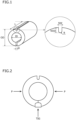
- the C-ring type restraint weld cracking test specimen was a test specimen having an outer diameter OD of 6 mm, an inner diameter ID of 4 mm, and a length L of 20 mm, and in which a cross section perpendicular to the pipe axis direction of the test specimen was a ring shape in which one part was open. As illustrated in FIG. 1 , a gap G of 1.5 mm was formed at the opening.
- a notch portion was formed at a position at 180° from the opening with respect to the central axis of the test specimen when viewing the C-ring type restraint weld cracking test specimen in the pipe axis direction.
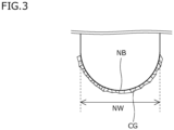
- a width NW of the notch portion was set to 0.4 mm, a depth NOD was set to 0.5 mm, and a radius of curvature R of the bottom portion was set to 0.2 mm.
- the C-ring type restraint weld cracking test specimen that had undergone the autogenous welding was subjected to a heat treatment in which the C-ring type restraint weld cracking test specimen was held at 650°C for 500 hours. After the heat treatment, the number of cracks which had occurred in the bottom of the notch of the C-ring type restraint weld cracking test specimen was counted. Specifically, crack observation test specimens that each included a cross section perpendicular to the pipe axis direction of the C-ring type restraint weld cracking test specimen which included the notch bottom of the C-ring type restraint weld cracking test specimen were collected at three locations in the pipe axis direction.
- the stress relaxation cracking resistance was evaluated as follows according to the obtained crack occurrence rate.
Landscapes
- Chemical & Material Sciences (AREA)
- Engineering & Computer Science (AREA)
- Mechanical Engineering (AREA)
- Materials Engineering (AREA)
- Metallurgy (AREA)
- Organic Chemistry (AREA)
- Physics & Mathematics (AREA)
- Thermal Sciences (AREA)
- Crystallography & Structural Chemistry (AREA)
- Manufacturing & Machinery (AREA)
- Oil, Petroleum & Natural Gas (AREA)
- Heat Treatment Of Steel (AREA)
Abstract
An austenitic stainless alloy material that has excellent creep strength and excellent stress relaxation cracking resistance is provided. An austenitic stainless alloy material according to the present disclosure contains, in mass%, C: 0.03 to 0.12%, Si: 0.05 to 2.00%, Mn: 0.05 to 3.00%, P: 0.03% or less, S: 0.010% or less, Ni: 18.0 to less than 25.0%, Cr: 22.0 to less than 30.0%, Co: 0.04 to 0.80%, Ti: 0.002 to 0.010%, Nb: 0.1 to 1.0%, V: 0.01 to 1.00%, Al: 0.001 to less than 0.030%, and N: 0.10 to 0.35%. The number density of precipitates having an equivalent circular diameter of 0.5 to 2.0 µm is 5000 pieces/mm2 or more.
Description
- The present disclosure relates to an alloy material, and more particularly relates to an austenitic stainless alloy material.
- Austenitic stainless alloy materials are used as a raw material for boilers such as coal-fired power boilers, biomass boilers, and HRSG (Heat Recovery Steam Generators). Raw materials that are used in these boilers are required to have excellent creep strength in high-temperature environments.
- Austenitic stainless alloy materials in which the creep strength is increased are proposed in International Application Publication No.
WO2009/044796 (Patent Literature 1) andJapanese Patent Application Publication No. 2004-250783 - Patent Literature 1 discloses an austenitic stainless alloy material that consists of, in mass%, C: 0.04 to 0.18%, Si: 1.5% or less, Mn: 2.0% or less, Ni: 6 to 30%, Cr: 15 to 30%, N: 0.03 to 0.35%, and sol. Al: 0.03% or less, and also contains one or more types among Nb: 1.0% or less, V: 0.5% or less, and Ti: 0.5% or less, with the balance being Fe and impurities. In addition, in this alloy material, P1 (= S+{(P+Sn)/2}+{(As+Zn+Pb+Sb)/5}) is 0.06 or less, and P2 (= Nb+2(V+Ti)) is 0.2 to 1.7-10xP1. In the alloy material disclosed in Patent Literature 1, by making P2 that is an index of Nb, V, and Ti 0.2 or more, precipitates are formed during use in a high-temperature environment and the creep strength is increased.
- Patent Literature 2 discloses an austenitic stainless alloy material that consists of, in mass%, C: 0.03 to 0.12%, Si: 0.2 to 2%, Mn: 0.1 to 3%, P: 0.03% or less, S: 0.01% or less, Ni: more than 1 8% to less than 25%, Cr: more than 22% to less than 30%, Co: 0.04 to 0.8%, Ti: 0.002% or more and less than 0.01%, Nb: 0.1 to 1%, V: 0.01 to 1%, B: more than 0.0005% to 0.2% or less, sol. Al: 0.0005% or more to less than 0.03%, N: 0.1 to 0.35%, and O (oxygen): 0.001 to 0.008%, with the balance being Fe and impurities. In the alloy material disclosed in Patent Literature 2, by containing Ti, Nb, and V, precipitates are formed during use in a high-temperature environment and the creep strength is increased.
-
- Patent Literature 1: International Application Publication No.
WO2009/044796 - Patent Literature 2:
Japanese Patent Application Publication No. 2004-250783 - In this connection, when austenitic stainless alloy materials for boiler use are applied for use in a boiler, the austenitic stainless alloy materials are welded or subjected to bending. Austenitic stainless alloy materials that are applied for use in boilers are used for long periods of time in a high temperature range of 500 to 750°C. At such time, relaxation of residual stress occurs at a weld zone of the austenitic stainless alloy material or at a portion subjected to bending. Due to the relaxation of residual stress, precipitates form within grains and the interior of the grains hardens. Consequently, creep strain may sometimes accumulate at grain boundaries and a crack may occur at the grain boundaries. A crack of this kind is called a "stress relaxation crack".
- An austenitic stainless alloy material for boiler use is required to have not only excellent creep strength, but also excellent stress relaxation cracking resistance. In the aforementioned Patent Literatures, although creep strength is discussed, there is no discussion regarding stress relaxation cracking resistance.
- An objective of the present disclosure is to provide an austenitic stainless alloy material that has excellent creep strength and excellent stress relaxation cracking resistance.
- An austenitic stainless alloy material according to the present disclosure consists of, in mass%,
- C: 0.03 to 0.12%,
- Si: 0.05 to 2.00%,
- Mn: 0.05 to 3.00%,
- P: 0.03% or less,
- S: 0.010% or less,
- Ni: 18.0 to less than 25.0%,
- Cr: 22.0 to less than 30.0%,
- Co: 0.04 to 0.80%,
- Ti: 0.002 to 0.010%,
- Nb: 0.1 to 1.0%,
- V: 0.01 to 1.00%,
- Al: 0.001 to less than 0.030%,
- N: 0.10 to 0.35%,
- Mo: 0 to 1.00%,
- W: 0 to 1.00%,
- B: 0 to 0.010%, and
- Ca: 0 to 0.0100%,
- with the balance being Fe and impurities,
- wherein a number density of precipitates having an equivalent circular diameter of 0.5 to 2.0 µm is 5000 pieces/mm2 or more.
- The austenitic stainless alloy material of the present disclosure has excellent creep strength and excellent stress relaxation cracking resistance.
-
- [
FIG. 1] FIG. 1 is a perspective view of a C-ring type restraint weld cracking test specimen used in a stress relaxation cracking resistance evaluation test. - [
FIG. 2] FIG. 2 is a schematic diagram for describing a method for carrying out a stress relaxation cracking resistance evaluation test using the C-ring type restraint weld cracking test specimen illustrated inFIG. 1 . - [
FIG. 3] FIG. 3 is an enlarged view of a portion in the vicinity of the bottom of a notch in a cross section perpendicular to the pipe axis direction of a C-ring type restraint weld cracking test specimen in a stress relaxation cracking resistance evaluation test in the Examples. - The present inventors conducted studies regarding an austenitic stainless alloy material which can achieve both excellent creep strength and excellent stress relaxation cracking resistance. First, the present inventors attempted to achieve both excellent creep strength and excellent stress relaxation cracking resistance from the viewpoint of the chemical composition. As a result, the present inventors considered that if the chemical composition consists of, in mass%, C: 0.03 to 0.12%, Si: 0.05 to 2.00%, Mn: 0.05 to 3.00%, P: 0.03% or less, S: 0.010% or less, Ni: 18.0 to less than 25.0%, Cr: 22.0 to less than 30.0%, Co: 0.04 to 0.80%, Ti: 0.002 to 0.010%, Nb: 0.1 to 1.0%, V: 0.01 to 1.00%, Al: 0.001 to less than 0.030%, N: 0.10 to 0.35%, Mo: 0 to 1.00%, W: 0 to 1.00%, B: 0 to 0.010%, and Ca: 0 to 0.0100%, with the balance being Fe and impurities, there is a possibility that both excellent creep strength and excellent stress relaxation cracking resistance can be achieved.
- Therefore, in addition, the present inventors conducted studies from the viewpoint of the microstructure with regard to achieving both excellent creep strength and excellent stress relaxation cracking resistance in an austenitic stainless alloy material that satisfies the chemical composition described above.
- Usually, in an austenitic stainless alloy material for boiler use, during use in a high-temperature environment, fine precipitates such as Ti precipitates, Nb precipitates, and V precipitates are formed and the creep strength is increased by precipitation strengthening by these precipitates. Therefore, in the austenitic stainless alloy material disclosed in Patent Literature 1 or Patent Literature 2, a heat treatment (solution treatment) is performed in the final stage of the production process. By this means, precipitates in the austenitic stainless alloy material are melted as much as possible, and Ti, Nb, and V are placed in a dissolved state. This is because, when the austenitic stainless alloy material is being used in a high-temperature environment, fine precipitates are formed by these dissolved elements and the creep strength is thereby increased.
- However, the present inventors considered that rather than reducing precipitates in the austenitic stainless alloy material and placing Ti, Nb, and V in a dissolved state as has been done in the past, by intentionally causing fine precipitates to be present in advance in the austenitic stainless alloy material, it would be possible to increase not only the creep strength but also the stress relaxation cracking resistance.
- The grains of an austenitic stainless alloy material can be kept fine by the pinning effect of fine precipitates that are present in advance in the austenitic stainless alloy material. In this case, the grain boundary area in the alloy material increases. By such increase in the grain boundary area, the stress relaxation cracking resistance can be increased.
- On the other hand, in a case where precipitates are present in advance in an austenitic stainless alloy material, it is difficult for new fine precipitates to form during use in a high-temperature environment. In addition, it is also conceivable that during use in a high-temperature environment, the precipitates that are already present will coarsen. In such case, there is a possibility that sufficient creep strength will not be obtained. However, as a result of studies conducted by the present inventors, it has been revealed that if precipitates having an equivalent circular diameter of 0.5 to 2.0 µm are present in an amount equivalent to a number density of 5000 pieces/mm2 or more in an austenitic stainless alloy material having the above chemical composition before being applied for used in a boiler, sufficient creep strength is obtained even during use in a high-temperature environment.
- Based on the above findings, the present inventors have discovered that instead of increasing the creep strength in a high-temperature environment by reducing precipitates as much as possible in an alloy material as in the case of the conventional austenitic stainless alloy materials such as are disclosed in Patent Literature 1 and Patent Literature 2, excellent creep strength and excellent stress relaxation cracking resistance can both be achieved by intentionally causing fine precipitates to be present in an amount equivalent to a number density of 5000 pieces/mm2 or more in the austenitic stainless alloy material, and thus completed the austenitic stainless alloy material of the present embodiment.
- The austenitic stainless alloy material of the present embodiment, which has been completed based on the technical idea described above, is as follows.
- [1] An austenitic stainless alloy material consisting of, in mass%,
- C: 0.03 to 0.12%,
- Si: 0.05 to 2.00%,
- Mn: 0.05 to 3.00%,
- P: 0.03% or less,
- S: 0.010% or less,
- Ni: 18.0 to less than 25.0%,
- Cr: 22.0 to less than 30.0%,
- Co: 0.04 to 0.80%,
- Ti: 0.002 to 0.010%,
- Nb: 0.1 to 1.0%,
- V: 0.01 to 1.00%,
- Al: 0.001 to less than 0.030%,
- N: 0.10 to 0.35%,
- Mo: 0 to 1.00%,
- W: 0 to 1.00%,
- B: 0 to 0.010%, and
- Ca: 0 to 0.0100%,
- with the balance being Fe and impurities,
- wherein a number density of precipitates having an equivalent circular diameter of 0.5 to 2.0 µm is 5000 pieces/mm2 or more.
- [2] The austenitic stainless alloy material according to [1], containing one kind of element or more selected from a group consisting of:
- Mo: 0.01 to 1.00%,
- W: 0.01 to 1.00%,
- B: 0.001 to 0.010%, and
- Ca: 0.0001 to 0.0100%.
- Hereunder, the austenitic stainless alloy material of the present embodiment is described in detail.
- The austenitic stainless alloy material of the present embodiment satisfies the following Feature 1 and Feature 2.
- The chemical composition consists of, in mass%, C: 0.03 to 0.12%, Si: 0.05 to 2.00%, Mn: 0.05 to 3.00%, P: 0.03% or less, S: 0.010% or less, Ni: 18.0 to less than 25.0%, Cr: 22.0 to less than 30.0%, Co: 0.04 to 0.80%, Ti: 0.002 to 0.010%, Nb: 0.1 to 1.0%, V: 0.01 to 1.00%, Al: 0.001 to less than 0.030%, N: 0.10 to 0.35%, Mo: 0 to 1.00%, W: 0 to 1.00%, B: 0 to 0.010%, and Ca: 0 to 0.0100%, with the balance being Fe and impurities.
- The number density of precipitates having an equivalent circular diameter of 0.5 to 2.0 µm is 5000 pieces/mm2 or more.
- Hereunder, Feature 1 and Feature 2 are described.
- The chemical composition of the austenitic stainless alloy material of the present embodiment contains the following elements.
- Carbon (C) increases the creep strength of the alloy material in a high-temperature environment. If the content of C is less than 0.03%, the aforementioned advantageous effect will not be sufficiently obtained even if the contents of other elements are within the range of the present embodiment.
- On the other hand, if the content of C is more than 0.12%, even if the contents of other elements are within the range of the present embodiment, M23C6-type Cr carbides will form at grain boundaries. In such case, Cr-depleted zones will form at the grain boundaries. Consequently, the stress relaxation cracking resistance of the alloy material will decrease.
- A preferable lower limit of the content of C is more than 0.03%, more preferably is 0.04%, and further preferably is 0.05%.
- A preferable upper limit of the content of C is 0.11%, more preferably is 0.10%, and further preferably is 0.09%.
- Silicon (Si) deoxidizes the alloy in the steelmaking process. Si also increases the oxidation resistance of the alloy material in a high-temperature environment. If the content of Si is less than 0.05%, the aforementioned advantageous effects will not be sufficiently obtained even if the contents of other elements are within the range of the present embodiment.
- On the other hand, if the content of Si is more than 2.00%, the weld hot cracking resistance will decrease even if the contents of other elements are within the range of the present embodiment.
- Therefore, the content of Si is 0.05 to 2.00%.
- A preferable lower limit of the content of Si is 0.10%, more preferably is 0.15%, further preferably is 0.18%, and further preferably is 0.20%.
- A preferable upper limit of the content of Si is 1.80%, more preferably is 1.60%, further preferably is 1.40%, further preferably is 1.30%, and further preferably is 1.25%.
- Manganese (Mn) deoxidizes a weld zone of the alloy material during welding. Mn also stabilizes austenite. If the content of Mn is less than 0.05%, the aforementioned advantageous effects will not be sufficiently obtained even if the contents of other elements are within the range of the present embodiment.
- On the other hand, if the content of Mn is more than 3.00%, even if the contents of other elements are within the range of the present embodiment, sigma phase (σ phase) will easily form during use in a high-temperature environment. The σ phase will reduce the toughness and creep ductility of the alloy material in a high-temperature environment.
- Therefore, the content of Mn is 0.05 to 3.00%.
- A preferable lower limit of the content of Mn is 0.10%, more preferably is 0.15%, further preferably is 0.20%, further preferably is 0.30%, further preferably is 0.40%, and further preferably is 0.45%.
- A preferable upper limit of the content of Mn is less than 3.00%, more preferably is 2.99%, further preferably is 2.95%, further preferably is 2.90%, further preferably is 2.80%, further preferably is 2.60%, further preferably is 2.40%, further preferably is 2.35%, further preferably is 2.20%, and further preferably is 2.00%.
- Phosphorus (P) is unavoidably contained. In other words, the content of P is more than 0%.
- P segregates to grain boundaries of the alloy material. If the content of P is more than 0.03%, even if the contents of other elements are within the range of the present embodiment, the aforementioned segregation will occur and the stress relaxation cracking resistance will decrease.
- Therefore, the content of P is 0.03% or less.
- The content of P is preferably as low as possible. However, excessively reducing the content of P will raise the production cost of the alloy material. Therefore, when normal industrial manufacturing is taken into consideration, a preferable lower limit of the content of P is 0.01 %.
- A preferable upper limit of the content of P is 0.02%.
- Sulfur (S) is unavoidably contained. In other words, the content of S is more than 0%.
- S segregates to grain boundaries of the alloy material. If the content of S is more than 0.010%, even if the contents of other elements are within the range of the present embodiment, the aforementioned segregation will occur and the stress relaxation cracking resistance will decrease.
- Therefore, the content of S is 0.010% or less.
- The content of S is preferably as low as possible. However, excessively reducing the content of S will raise the production cost of the alloy material. Therefore, when normal industrial manufacturing is taken into consideration, a preferable lower limit of the content of S is 0.001%.
- A preferable upper limit of the content of S is 0.008%, more preferably is 0.006%, further preferably is 0.004%, and further preferably is 0.003%.
- Nickel (Ni) stabilizes austenite and increases the creep strength of the alloy material in a high-temperature environment. If the content of Ni is less than 18.0%, the aforementioned advantageous effect will not be sufficiently obtained even if the contents of other elements are within the range of the present embodiment.
- On the other hand, if the content of Ni is 25.0% or more, the aforementioned advantageous effect will be saturated. In addition, the production cost will increase.
- Therefore, the content of Ni is 18.0 to less than 25.0%.
- A preferable lower limit of the content of Ni is 18.4%, more preferably is 18.8%, further preferably is 19.2%, and further preferably is 19.5%.
- A preferable upper limit of the content of Ni is 24.9%, more preferably is 24.8%, further preferably is 24.4%, further preferably is 24.0%, and further preferably is 23.6%.
- Chromium (Cr) increases the corrosion resistance of the alloy material in a high-temperature environment. If the content of Cr is less than 22.0%, the aforementioned advantageous effect will not be sufficiently obtained even if the contents of other elements are within the range of the present embodiment.
- On the other hand, if the content of Cr is 30.0% or more, the stability of austenite in a high-temperature environment will decrease even if the contents of other elements are within the range of the present embodiment. In such case, the creep strength of the alloy material will decrease.
- Therefore, the content of Cr is 22.0 to less than 30.0%.
- A preferable lower limit of the content of Cr is 22.5%, more preferably is 23.0%, and further preferably is 23.5%.
- A preferable upper limit of the content of Cr is 29.9%, more preferably is 29.8%, further preferably is 29.5%, further preferably is 29.0%, further preferably is 28.5%, further preferably is 28.0%, further preferably is 27.5%, and further preferably is 27.0%.
- Cobalt (Co) stabilizes austenite and increases the creep strength of the alloy material in a high-temperature environment. If the content of Co is less than 0.04%, the aforementioned advantageous effect will not be sufficiently obtained even if the contents of other elements are within the range of the present embodiment.
- On the other hand, if the content of Co is more than 0.80%, the raw material cost will increase.
- Therefore, the content of Co is 0.04 to 0.80%.
- A preferable lower limit of the content of Co is 0.05%, more preferably is 0.06%, and further preferably is 0.08%.
- A preferable upper limit of the content of Co is 0.70%, more preferably is 0.60%, further preferably is 0.55%, and further preferably is 0.50%.
- Titanium (Ti) forms Ti precipitates and thereby increases the creep strength of the alloy material in a high-temperature environment. In addition, by formation of the Ti precipitates, Ti increases the stress relaxation cracking resistance of the alloy material. If the content of Ti is less than 0.002%, the aforementioned advantageous effects will not be sufficiently obtained even if the contents of other elements are within the range of the present embodiment.
- On the other hand, if the content of Ti is more than 0.010%, coarse Ti precipitates will form even if the contents of other elements are within the range of the present embodiment. In this case, during welding, the weld hot cracking resistance in a weld-heat affected zone formed in the alloy material will decrease.
- Therefore, the content of Ti is 0.002 to 0.010%.
- A preferable lower limit of the content of Ti is 0.003%, and more preferably is 0.004%.
- A preferable upper limit of the content of Ti is 0.009%, and more preferably is 0.008%.
- Niobium (Nb) forms Nb precipitates and increases the creep strength of the alloy material in a high-temperature environment. In addition, by formation of the Nb precipitates, Nb increases the stress relaxation cracking resistance of the alloy material. If the content of Nb is less than 0.1%, the aforementioned advantageous effects will not be sufficiently obtained even if the contents of other elements are within the range of the present embodiment.
- On the other hand, if the content of Nb is more than 1.0%, during welding of the alloy material, the weld hot cracking resistance in a weld-heat affected zone of the alloy material will decrease even if the contents of other elements are within the range of the present embodiment.
- Therefore, the content of Nb is 0.1 to 1.0%.
- A preferable lower limit of the content of Nb is 0.2%, more preferably is 0.3%, and further preferably is 0.4%.
- A preferable upper limit of the content of Nb is 0.9%, more preferably is 0.8%, and further preferably is 0.7%.
- Vanadium (V) forms V precipitates and increases the creep strength of the alloy material in a high-temperature environment. In addition, by formation of the V precipitates, V increases the stress relaxation cracking resistance of the alloy material. If the content of V is less than 0.01%, the aforementioned advantageous effects will not be sufficiently obtained even if the contents of other elements are within the range of the present embodiment.
- On the other hand, if the content of V is more than 1.00%, during welding of the alloy material, the weld hot cracking resistance in a weld-heat affected zone of the alloy material will decrease even if the contents of other elements are within the range of the present embodiment.
- Therefore, the content of V is 0.01 to 1.00%.
- A preferable lower limit of the content of V is 0.02%, more preferably is 0.03%, and further preferably is 0.04%.
- A preferable upper limit of the content of V is 0.80%, more preferably is 0.75%, further preferably is 0.70%, further preferably is 0.65%, further preferably is 0.60%, further preferably is 0.40%, further preferably is 0.35%, and further preferably is 0.25%.
- Aluminum (Al) deoxidizes the alloy in the steelmaking process. Al also increases the oxidation resistance of the alloy material in a high-temperature environment. If the content of Al is less than 0.001%, the aforementioned advantageous effects will not be sufficiently obtained even if the contents of other elements are within the range of the present embodiment.
- On the other hand, if the content of Al is 0.030% or more, the hot workability of the alloy material will decrease even if the contents of other elements are within the range of the present embodiment.
- Therefore, the content of Al is 0.001 to less than 0.030%.
- A preferable lower limit of the content of Al is 0.002%, more preferably is 0.003%, and further preferably is 0.005%.
- A preferable upper limit of the content of Al is 0.029%, more preferably is 0.028%, further preferably is 0.027%, further preferably is 0.026%, and further preferably is 0.025%.
- Note that, the phrase "content of Al" refers to the content (mass%) of acidsoluble Al (sol. Al).
- Nitrogen (N) dissolves in the matrix (parent phase) and stabilizes austenite. The dissolved N also forms fine nitrides in the alloy material during use in a high-temperature environment. The fine nitrides strengthen Cr-depleted zones. Consequently, the stress relaxation cracking resistance of the alloy material increases. The fine nitrides that are formed during use in a high-temperature environment also increase the creep strength of the alloy material by precipitation strengthening. If the content of N is less than 0.10%, the aforementioned advantageous effects will not be sufficiently obtained even if the contents of other elements are within the range of the present embodiment.
- On the other hand, if the content of N is more than 0.35%, coarse nitrides will form even if the contents of other elements are within the range of the present embodiment. The coarse nitrides will reduce the toughness of the alloy material.
- Therefore, the content of N is 0.10 to 0.35%.
- A preferable lower limit of the content of N is 0.11 %, more preferably is 0.12%, further preferably is 0.14%, and further preferably is 0.16%.
- A preferable upper limit of the content of N is 0.33%, more preferably is 0.31%, and further preferably is 0.29%.
- The balance of the chemical composition of the austenitic stainless alloy material according to the present embodiment is Fe and impurities. Here, the term "impurities" means substances which are mixed in from ore and scrap used as the raw material or from the production environment or the like when industrially producing the austenitic stainless alloy material, and which are substances that are not intentionally contained but are permitted within a range that does not adversely affect the austenitic stainless alloy material of the present embodiment.
- The chemical composition of the austenitic stainless alloy material of the present embodiment may further contain, in lieu of a part of Fe, one kind of element or more selected from the group consisting of:
- Mo: 0 to 1.00%,
- W: 0 to 1.00%,
- B: 0 to 0.010%, and
- Ca: 0 to 0.0100%.
- Each of these elements is an optional element, and does not have to be contained. Hereunder, these optional elements are described.
- The chemical composition of the austenitic stainless alloy material of the present embodiment may further contain, in lieu of a part of Fe, one kind of element or more selected from the group consisting of Mo and W. These elements are optional elements, and each of these elements increases the creep strength of the austenitic stainless alloy material.
- Molybdenum (Mo) is an optional element, and does not have to be contained. That is, the content of Mo may be 0%.
- When Mo is contained, that is, when the content of Mo is more than 0%, during use in a high-temperature environment, Mo increases the creep strength of the alloy material by solid-solution strengthening. If even a small amount of Mo is contained, the aforementioned advantageous effect will be obtained to a certain extent.
- However, if the content of Mo is more than 1.00%, even if the contents of other elements are within the range of the present embodiment, intermetallic compounds such as Laves phases will form within the grains. In such case, secondary induced precipitation hardening will increase and the strength difference between the inside of the grains and the grain boundaries will be large. Consequently, the stress relaxation cracking resistance will decrease.
- Therefore, the content of Mo is 0 to 1.00%, and when contained, the content of Mo is 1.00% or less.
- A preferable lower limit of the content of Mo is more than 0%, more preferably is 0.01%, further preferably is 0.03%, further preferably is 0.05%, and further preferably is 0.08%.
- A preferable upper limit of the content of Mo is 0.90%, more preferably is 0.85%, further preferably is 0.80%, further preferably is 0.70%, further preferably is 0.60%, further preferably is 0.50%, further preferably is 0.40%, and further preferably is 0.30%.
- Tungsten (W) is an optional element, and does not have to be contained. In other words, the content of W may be 0%.
- When W is contained, that is, when the content of W is more than 0%, during use of the alloy material in a high-temperature environment, W increases the creep strength of the alloy material by solid-solution strengthening. If even a small amount of W is contained, the aforementioned advantageous effect will be obtained to a certain extent.
- However, if the content of W is more than 1.00%, even if the contents of other elements are within the range of the present embodiment, intermetallic compounds such as Laves phases will form within the grains. In such case, secondary induced precipitation hardening will increase and the strength difference between the inside of the grains and the grain boundaries will be large. Consequently, the stress relaxation cracking resistance will decrease.
- Therefore, the content of W is 0 to 1.00%, and when contained, the content of W is 1.00% or less.
- A preferable lower limit of the content of W is more than 0%, more preferably is 0.01%, further preferably is 0.03%, further preferably is 0.05%, and further preferably is 0.10%.
- A preferable upper limit of the content of W is 0.90%, more preferably is 0.80%, further preferably is 0.70%, further preferably is 0.60%, further preferably is 0.50%, further preferably is 0.40%, further preferably is 0.35%, and further preferably is 0.30%.
- The austenitic stainless alloy material of the present embodiment may further contain B.
- Boron (B) is an optional element, and does not have to be contained. That is, the content of B may be 0%.
- When B is contained, that is, when the content of B is more than 0%, B segregates to grain boundaries in a high-temperature environment and thereby increases the grain boundary strength. Consequently, the stress relaxation cracking resistance of the alloy material increases. If even a small amount of B is contained, the aforementioned advantageous effect will be obtained to a certain extent.
- However, if the content of B is more than 0.010%, even if the contents of other elements are within the range of the present embodiment, B will promote the formation of Cr carbides at grain boundaries. In such case, the stress relaxation cracking resistance of the alloy material will decrease.
- Therefore, the content of B is 0 to 0.010%, and when contained, the content of B is 0.010% or less.
- A preferable lower limit of the content of B is more than 0%, more preferably is 0.001%, and further preferably is 0.002%).
- A preferable upper limit of the content of B is 0.009%, more preferably is 0.008%, further preferably is 0.007%, and further preferably is 0.006%.
- The austenitic stainless alloy material of the present embodiment may further contain Ca.
- Calcium (ca) is an optional element, and does not have to be contained. That is, the content of Ca may be 0%.
- When Ca is contained, that is, when the content of Ca is more than 0%, Ca immobilizes O (oxygen) and S (sulfur) as inclusions, and thereby increases the hot workability of the alloy material. If even a small amount of Ca is contained, the aforementioned advantageous effect will be obtained to a certain extent.
- However, if the content of Ca is more than 0.0100%, even if the contents of other elements are within the range of the present embodiment, the cleanliness of the alloy material will decrease, and the hot workability of the alloy material will decrease.
- Therefore, the content of Ca is 0 to 0.0100%, and when contained, the content of Ca is 0.0100% or less.
- A preferable lower limit of the content of Ca is more than 0%, more preferably is 0.0001%, further preferably is 0.0003%, further preferably is 0.0005%, further preferably is 0.0008%, and further preferably is 0.0010%.
- A preferable upper limit of the content of Ca is 0.0090%, more preferably is 0.0080%, further preferably is 0.0070%, further preferably is 0.0060%, further preferably is 0.0050%, and further preferably is 0.0045%.
- In the austenitic stainless alloy material of the present embodiment, in addition, a number density ND of precipitates having an equivalent circular diameter of 0.5 to 2.0 µm is 5000 pieces/mm2 or more.
- As described above, in the conventional austenitic stainless alloy materials, precipitates in the alloy material are reduced as much as possible by carrying out a solution treatment. However, in the austenitic stainless alloy material of the present embodiment, both excellent creep strength and excellent stress relaxation cracking resistance are obtained by purposely causing precipitates of a specific size to be present in the alloy material.
- Here, precipitates having an equivalent circular diameter of 0.5 to 2.0 µm are defined as "fine precipitates". The fine precipitates keep the grains of the austenitic stainless alloy material fine by a pinning effect. By this means, the grain boundary area in the austenitic stainless alloy material increases, and the stress relaxation cracking resistance is increased. In addition, fine precipitates having an equivalent circular diameter of 0.5 to 2.0 µm exhibit a precipitation strengthening ability during use under a high-temperature environment, and thereby increase the creep strength of the austenitic stainless alloy material.
- In an austenitic stainless alloy material that satisfies Feature 1, if the number density ND of fine precipitates is 5000 pieces/mm2 or more, excellent creep strength and excellent stress relaxation cracking resistance can both be achieved.
- A preferable lower limit of the number density ND of fine precipitates is 5200 pieces/mm2, more preferably is 5500 pieces/mm2, further preferably is 6000 pieces/mm2, and further preferably is 6200 pieces/mm2.
- The upper limit of the number density ND of fine precipitates is not particularly limited. When the austenitic stainless alloy material satisfies Feature 1, the upper limit of the number density ND of fine precipitates is, for example, 20000 pieces/mm2, or for example is 18000 pieces/mm2, or for example is 15000 pieces/mm2
- [Method for measuring number density ND of fine precipitates
- The number density ND of fine precipitates can be determined by the following method.
- First, a test specimen is taken from the austenitic stainless alloy material. If the austenitic stainless alloy material is an alloy pipe, a test specimen that includes a central portion of the wall thickness is taken. Among the surfaces of the test specimen, a surface that is a cross section perpendicular to the axial direction of the alloy pipe and that includes the central portion of the wall thickness is to be set as the observation surface, and the central portion of the wall thickness is to be set as the observation visual field.
- If the austenitic stainless alloy material is an alloy plate, a test specimen including a center portion of the thickness is taken. Among the surfaces of the test specimen, a surface that is a cross section perpendicular to the rolling direction of the alloy plate and that includes the center portion of the thickness is to be set as the observation surface, and the center portion of the thickness is to be set as the observation visual field.
- If the austenitic stainless alloy material is a bar, a test specimen that includes an R/2 portion is taken. Here, "R" means the radius of a cross section perpendicular to the axial direction of the bar. The term "R/2 portion" means the center portion of the radius in the aforementioned cross section. Among the surfaces of the test specimen, a surface that is a cross section perpendicular to the longitudinal direction of the bar and that includes the R/2 portion is to be set as the observation surface, and the R/2 portion is to be set as the observation visual field.
- The observation surface is mirror-polished, and thereafter a photograph of the microstructure in the observation visual field on the observation surface after mirror polishing is obtained at a magnification of x 500 using an optical microscope. The area of the observation visual field is to be set to 140 µm × 160 µm.
- The microstructure photograph obtained by the optical microscope observation is used to determine the equivalent circular diameter of particles in the observation visual field. Here, the term "equivalent circular diameter" means the diameter of a circle having the same area as the area of the particle. The equivalent circular diameter can be obtained by well-known image processing. Particles observed during the visual field observation can be easily identified by means of contrast. Particles having an equivalent circular diameter of 0.5 to 2.0 µm are recognized as precipitates (fine precipitates). The number density (pieces/mm2) of fine precipitates is determined based on the number of all the fine precipitates in the observation visual field and the area of the observation visual field. Note that, the fine precipitates are, for example, any one or more kinds among Ti precipitates containing Ti, Nb precipitates containing Nb, and V precipitates containing V.
- The austenitic stainless alloy material of the present embodiment satisfies Feature 1 and Feature 2. As a result, the austenitic stainless alloy material of the present embodiment can achieve both excellent creep strength and excellent stress relaxation cracking resistance.
- The microstructure of the alloy material of the present embodiment consists of austenite.
- The shape of the austenitic stainless alloy material of the present embodiment is not particularly limited. The austenitic stainless alloy material may be an alloy pipe, or may be an alloy plate. The austenitic stainless alloy material may also be a bar. Preferably, the austenitic stainless alloy material of the present embodiment is an alloy pipe.
- A method for producing the austenitic stainless alloy material of the present embodiment will now be described.
- The production method described hereunder is one example of a method for producing the austenitic stainless alloy material of the present embodiment. Accordingly, the austenitic stainless alloy material of the present embodiment may also be produced by a production method other than the method described hereunder. However, the production method described hereunder is a preferable example of a method for producing the austenitic stainless alloy material of the present embodiment.
- A method for producing the alloy material of the present embodiment includes the following processes.
- (Process 1) Preparation process
- (Process 2) Hot working process
- (Process 3) High-temperature holding process
- (Process 4) Cold working process
- (Process 5) Precipitation heat treatment process
- In the above production process, when a holding temperature in the high-temperature holding process is defined as T1 (°C), a holding time at the holding temperature T1 is defined as t1 (mins), a heat treatment temperature in the precipitation heat treatment process is defined as T2 (°C), and a holding time at the heat treatment temperature T2 is defined as t2 (mins), the following Formula (A) to Formula (C) are satisfied:


- Hereunder, each process is described.
- In the preparation process, a starting material having a chemical composition satisfying the above Feature 1 is prepared. The starting material may be supplied by a third party or may be produced. The starting material may be an ingot, or may be a slab, a bloom, or a billet.
- In the case of producing the starting material, the starting material is produced by the following method. A molten alloy having a chemical composition satisfying the above Feature 1 is produced. The produced molten alloy is used to produce an ingot by an ingot-making process. The produced molten alloy may also be used to produce a slab, a bloom, or a billet by a continuous casting process. Hot working may be performed on the produced ingot, slab, or bloom to produce a billet. For example, hot forging may be performed on the ingot to produce a cylindrical billet, and the billet may be used as the starting material. In such case, although not particularly limited, the temperature of the starting material immediately before the start of the hot forging is, for example, 1100 to 1300°C. The method for cooling the starting material after hot forging is not particularly limited.
- In the hot working process, hot working is performed on the starting material prepared in the preparation process to thereby produce an intermediate alloy material. The intermediate alloy material, for example, may be an alloy pipe, may be an alloy plate, or may be an alloy bar.
- If the intermediate alloy material is an alloy pipe, the following working is performed in the hot working process. First, a cylindrical starting material is prepared. A through-hole is formed along the central axis in the cylindrical starting material by machining. The cylindrical starting material in which the through-hole has been formed is heated. The heated cylindrical starting material is then subjected to a hot-extrusion process, which is typified by the Ugine-Sejournet process, to produce the intermediate alloy material (alloy pipe). A hot hollow forging process may be performed instead of the hot extrusion process. Although not particularly limited, the heating temperature is, for example, 1100 to 1300°C.
- Further, instead of hot extrusion, an alloy pipe may be produced by performing piercing-rolling according to the Mannesmann process. In such case, the cylindrical starting material is heated. Although not particularly limited, the heating temperature is, for example, 1100 to 1300°C. The heated cylindrical starting material is subjected to piercing-rolling using a piercing machine to produce a hollow blank. The hollow blank is further subjected to elongating or diameter adjusting rolling with a mandrel mill, a stretch reducer, a sizing mill or the like to produce the intermediate alloy material (alloy pipe).
- If the intermediate alloy material is an alloy plate, for example, one or a plurality of rolling mills equipped with a pair of work, rolls is used in the hot working process. In this case, the starting material such as a slab is heated. Although not particularly limited, the heating temperature is, for example, 1100 to 1300°C. The heated starting material is subjected to hot rolling using the one or plurality of rolling mills to produce the intermediate alloy material (alloy plate).
- If the intermediate alloy material is an alloy bar, for example, the hot working process is performed using a blooming mill and/or a continuous mill in which a plurality of rolling mills are arranged in a row. In this case, the starting material is heated. Although not particularly limited, the heating temperature is, for example, 1100 to 1300°C. The heated starting material is subjected to hot rolling using the blooming mill and/or continuous mill to produce the intermediate alloy material (alloy bar).
- In the high-temperature holding process, the intermediate alloy material produced in the hot working process is held at a high temperature to cause precipitates in the intermediate alloy material to melt sufficiently. A holding temperature T1 (°C) and a holding time t1 (mins) at the holding temperature T1 in the high-temperature holding process are adjusted within the following ranges.
- Holding temperature T1: 1100 to 1350°C
- Holding time t1: 2 to 40 minutes
- In the high-temperature holding process, the intermediate alloy material which has been cooled to normal temperature in the hot working process may be heated to the holding temperature T1 and held at the holding temperature T1 for the holding time t1. Alternatively, the intermediate alloy material directly after the hot working process (that is, the intermediate alloy material which has not been cooled to normal temperature) may be held at the holding temperature T1 for the holding time t1. After the holding time t1 elapses, the intermediate alloy material is rapidly cooled. The rapid cooling may be water cooling or may be oil cooling.
- In the cold working process, cold working is performed on the intermediate alloy material after the intermediate alloy material has been subjected to a pickling treatment. If the intermediate alloy material is an alloy pipe or an alloy bar, the cold working is, for example, cold drawing. If the intermediate alloy material is an alloy plate, the cold working is, for example, cold rolling. Performing the cold working process enables refining of grains by recrystallization to occur in the precipitation heat treatment process that is the next process. Although not particularly limited, the reduction of area in the cold working process is, for example, 10 to 90%.
- In the precipitation heat treatment process, the intermediate alloy material after the cold working process is subjected to a heat treatment to form fine precipitates in the intermediate alloy material. A heat treatment temperature T2 (°C) and a holding time t2 (mins) at the heat treatment temperature T2 in the precipitation heat treatment process are adjusted within the following ranges.
- Heat treatment temperature T2: 1000 to 1350°C
- Holding time t2: 1 to 30 minutes
- After the holding time t2 elapses, the intermediate alloy material is rapidly cooled. The rapid cooling method may be water cooling or may be oil cooling.
- In the production process described above, furthermore, the holding temperature T1 (°C), the holding time t1 (mins), the heat treatment temperature T2 (°C), and the holding time t2 (mins) in the high-temperature holding process and the precipitation heat treatment process satisfy Formula (A) to Formula (C):


- Let F1 be defined as F1 = (1/20)×{(T1-700)2+t1}/(5Nb+30Ti+5V). F1 is a conditional expression for sufficiently melting precipitates (Nb precipitates, Ti precipitates, V precipitates and the like) in the intermediate alloy material in the high-temperature holding process. In the austenitic stainless alloy material of the present embodiment the content of N is 0.10 to 0.35%, which is high. In a case such as this in which the content of N is high, in order to sufficiently melt the Ti precipitates, a heat quantity corresponding to the content of Ti in the alloy material is required. Similarly, with regard to the Nb precipitates and the V precipitates, in order to sufficiently melt these precipitates, a heat quantity corresponding to the content of Nb and the content of V in the alloy material is required.
- In F1, the content of Nb, the content of Ti, and the content of V are placed in the denominator. That is, F1 is adjusted according to the content of Nb, the content of Ti, and the content of V in the alloy material. As described above, the content of N is high in the austenitic stainless alloy material of the present embodiment. Therefore, among Nb precipitates, Ti precipitates, and V precipitates, Ti that strongly bonds with N is the most difficult to melt. Therefore, the coefficient of Ti in F1 is large.
- If F1 is 4100 or more, in the high-temperature holding process, a sufficient heat quantity for melting Nb precipitates, Ti precipitates, and V precipitates in the intermediate alloy material will be imparted to the intermediate alloy material. Therefore, the precipitates that are present in the intermediate alloy material can be sufficiently melted.
- A preferable lower limit of F1 is 4200, and more preferably is 4300.
- In the production process described above, after the precipitates in the intermediate alloy material have been mostly melted in the high-temperature holding process, fine precipitates are formed in the intermediate alloy material in the precipitation heat treatment process. If the heat treatment temperature T2 is higher than the holding temperature T1, fine precipitates will not sufficiently form in the intermediate alloy material in the precipitation heat treatment process. Therefore, the holding temperature T1 is to be set to a temperature that is equal to or higher than the heat treatment temperature T2.
- In the precipitation heat treatment process, fine precipitates having an equivalent circular diameter of 0.5 to 2.0 µm are formed in the intermediate alloy material in which precipitates were sufficiently melted by the high-temperature holding process. In order to make the number density ND of fine precipitates 5000 pieces/mm2 or more, it is necessary to impart a heat quantity that corresponds to the content of Nb, the content of Ti, and the content of V in the intermediate alloy material to the intermediate alloy material.
- Let F2 be defined as F2 = (T2+t2)×(Nb+50Ti+20V). F2 is a conditional expression for making the number density ND of fine precipitates 5000 picces/mm2 or more. If F2 is 1000 or more, on the precondition that Formula (A) and Formula (B) are satisfied, the number density of fine precipitates will be 5000 pieces/mm2 or more.
- A preferable lower limit of F2 is 1020, more preferably is 1100, and further preferably is 1200.
- An austenitic stainless alloy material that satisfies Feature 1 and Feature 2 can be produced by the production process described above. Note that, a method for producing the austenitic stainless alloy material of the present embodiment is not limited to the production method described above. As long as an austenitic stainless alloy material that satisfies Feature 1 and Feature 2 can be produced, the austenitic stainless alloy material may also be produced by another production method.
- The advantageous effects of the austenitic stainless alloy material of the present embodiment will now be described more specifically by way of examples. The conditions adopted in the following examples are one example of conditions adopted for confirming the feasibility and advantageous effects of the austenitic stainless alloy material of the present embodiment. Accordingly, the austenitic stainless alloy material of the present embodiment is not limited to this one example of conditions.
- Ingots having the chemical compositions shown in Table 1-1 and Table 1-2 were produced.
-
TABLE 1-1 Number Chemical Composition (unit is mass%; balance is Fe and impurities) C Si Mn P S Ni Cr Co 1 0.07 0.53 1.03 0.01 0.001 21.1 25.4 0.21 2 0.09 0.81 1.71 0.01 0.001 20.5 28.4 0.15 3 0.05 0.21 0.81 0.01 0.001 22.1 24.9 0.22 4 0.06 1.04 1.20 0.01 0.001 24.5 23.4 0.13 5 0.06 0.78 0.87 0.01 0.001 21.5 25.3 0.08 6 0.04 0.58 1.43 0.02 0.002 18.9 25.1 0.09 7 0.06 0.41 1.22 0.02 0.001 19.8 25.0 0.35 8 0.11 1.03 0.59 0.01 0.001 22.9 27.9 0.18 9 0.08 0.08 0.11 0.01 0.002 23.2 28.8 0.71 10 0.09 1.81 2.31 0.01 0.001 18.3 26.0 0.11 11 0.07 0.67 2.70 0.01 0.001 21.5 26.1 0.09 12 0.07 0.77 1.33 0.01 0.006 21.7 25.8 0.11 13 0.05 0.58 1.48 0.02 0.002 24.3 25.0 0.09 14 0.10 0.63 1.08 0.02 0.001 19.6 26.4 0.21 15 0.06 1.04 1.20 0.01 0.001 24.5 23.4 0.13 16 0.04 0.26 1.94 0.01 0.002 21.8 24.3 0.08 17 0.05 1.20 0.89 0.02 0.001 23.6 22.5 0.46 18 0.05 1.20 0.89 0.02 0.001 23.6 22.5 0.46 19 0.04 1.15 0.91 0.01 0.002 23.7 22.4 0.44 -
TABLE1-2 Number Chemical Composition (unit is mass%; balance is Fe and impurities) Ti Nb V sol.Al N Mo W B Ca 1 0.007 0.5 0.03 0.012 0.24 - - - - 2 0.005 0.7 0.02 0.010 0.19 - - - - 3 0.003 0.6 0.02 0.010 0.21 0.21 - - - 4 0.004 0.4 0.11 0.009 0.18 - 0.17 - - 5 0.005 0.5 0.08 0.015 0.28 - - 0.005 - 6 0.003 0.3 0.03 0.010 0.22 - - - 0.0025 7 0.006 0.4 0.02 0.015 0.25 0.05 0.01 0.002 0.0010 8 0.008 0.6 0.05 0.011 0.29 0.13 0.32 0.005 0.0020 9 0.008 0.6 0.06 0.003 0.12 0.79 - - 0.0067 10 0.002 0.2 0.61 0.026 0.32 - 0.88 - - 11 0.003 0.8 0.02 0.011 0.23 - - - - 12 0.002 0.1 0.70 0.011 0.21 - - - - 13 0.010 0.4 0.32 0.010 0.22 - - - - 14 0.004 0.7 0.11 0.013 0.24 0.11 0.14 0.002 0.0030 15 0.004 0.4 0.11 0.009 0.30 - - - - 16 0.007 0.4 0.05 0.021 0.18 0.26 0.41 0.003 0.0020 17 0.006 0.3 0.21 0.009 0.31 0.21 0.08 0.006 0.0040 18 0.003 0.1 0.02 0.009 0.31 - - - - 19 0.002 0.2 0.03 0.008 0.30 - - - - - Each of the produced ingots was subjected to hot forging to produce a cylindrical starting material having a diameter of 180 mm. The heating temperature of the ingots in the hot forging was 1100 to 1300°C. The produced cylindrical starting material was subjected to a hot working process. Specifically, the starting material was heated in a reheating furnace. The heating temperature in the hot working process was 1100 to 1300°C. After being heated, the cylindrical starting material was subjected to a hot-extrusion process to produce a hollow shell.
- The produced hollow shell was subjected to a high-temperature holding process. The holding temperature T1 (°C) and holding time t1 (mins) in the high-temperature holding process were as shown in Table 2.
-
TABLE2 Number T1 (°C) t1 (mins) T2 (°C) t2 (mins) F1 T1≥T2? F2 Number Density ND (pieces/mm2) Stress Relaxation Cracking Resistance Creep Strength Remarks 1 1260 10 1210 2 5483 T 1757 8500 E E Inventive Example of Present Invention 2 1280 3 1230 3 4485 T 1665 12000 E E Inventive Example of Present Invention 3 1250 5 1240 4 4741 T 1431 11000 E E Inventive Example of Present Invention 4 1270 15 1200 3 6085 T 3368 10000 E E Inventive Example of Present Invention 5 1300 3 1250 10 5902 T 2961 9000 E E Inventive Example of Present Invention 6 1280 20 1200 8 9667 T 1268 6500 E E Inventive Example of Present Invention 7 1260 30 1210 10 6878 T 1342 8000 E E Inventive Example of Present Invention 8 1250 5 1250 2 4334 T 2504 9000 E E Inventive Example of Present Invention 9 1260 10 1210 2 4430 T 2666 6000 E E Inventive Example of Present Invention 10 1300 3 1230 3 4380 T 15413 7500 E E Inventive Example of Present Invention 11 1290 13 1250 2 4154 T 1690 8500 E E Inventive Example of Present Invention 12 1300 10 1250 2 4434 T 17778 7500 E E Inventive Example of Present Invention 13 1250 8 1200 5 3878 T 8797 4800 B E Comparative Example 14 1250 20 1250 8 3627 T 3900 4700 B E Comparative Example 15 1210 10 1280 5 4871 F 3598 4600 B E Comparative Example 16 1200 8 1250 5 5081 F 2196 4500 B E Comparative Example 17 1250 15 1320 3 5541 F 6350 4600 B E Comparative Example 18 1280 5 1080 3 24377 T 704 3500 B B Comparative Example 19 1280 10 1050 2 13901 T 947 3700 B B Comparative Example - Cold working was performed on the hollow shell after the high-temperature holding process. Specifically, the hollow shell was subjected to cold drawing. Note that, the reduction of area in the cold working was 20 to 70%.
- A precipitation heat treatment process was performed on the hollow shell after the cold working process. The heat treatment temperature T2 (°C) and the holding time t2 (mins) at the heat treatment temperature T2 in the precipitation heat treatment process were as shown in Table 2. Note that, the F1 value is shown in the column "F1" in Table 2. In the column "T1 ≥ T2?", "T (True)" indicates that the holding temperature T1 was equal to or higher than the heat treatment temperature T2, and "F (False)" indicates that the holding temperature T1 was less than the heat treatment temperature T2. The F2 value is shown in the column "F2".
- Austenitic stainless alloy materials (alloy pipes) were produced by the above production process.
- The following evaluation tests were carried out using the produced alloy materials.
- (Test 1) Test to measure number density ND of fine precipitates (Test 2) Creep strength evaluation test
- (Test 3) Stress relaxation cracking resistance evaluation test Hereunder, each evaluation test is described.
- The number density (pieces/mm2) of fine precipitates in the austenitic stainless alloy material of each test number was measured by the method described above in the section [Method for measuring number density ND of fine precipitates]. The obtained number density ND of fine precipitates is shown in the column "Number Density ND (pieces/mm2)" in Table 2.
- The following creep strength evaluation test was performed on the alloy material (alloy pipe) of each test number.
- A creep rupture test specimen in accordance with JIS Z2271: 2010 was taken from the central portion of the wall thickness of the alloy material (alloy pipe) of each test number. The cross section perpendicular to the axial direction of the parallel portion of the creep rupture test specimen was circular. The parallel portion had an outer diameter of 6 mm, and had a length of 30 mm. The longitudinal direction of the creep rupture test specimen was parallel to the axial direction of the alloy pipe.
- A creep rupture test conforming to JIS Z2271: 2010 was carried out using the prepared creep rupture test specimen. Specifically, the creep rupture test specimen was heated to 700°C. Thereafter, the creep rupture test was carried out. The test stress was set to 80 MPa. In the test, the creep rupture time (hours) was determined.
- The creep strength was evaluated as follows according to the obtained creep rupture time.
- Evaluation E (Excellent): Creep rupture time was 1,500 hours or more
- Evaluation B (Bad): Creep rupture time was less than 1,500 hours
- In the case of evaluation E, it was determined that excellent creep strength had been obtained. The evaluation results are shown in the column "Creep Strength" in Table 2.
- A C-ring type restraint weld cracking test specimen illustrated in
FIG. 1 was fabricated from a central portion of the wall thickness of the alloy material (alloy pipe) of each test number. The C-ring type restraint weld cracking test specimen was a test specimen having an outer diameter OD of 6 mm, an inner diameter ID of 4 mm, and a length L of 20 mm, and in which a cross section perpendicular to the pipe axis direction of the test specimen was a ring shape in which one part was open. As illustrated inFIG. 1 , a gap G of 1.5 mm was formed at the opening. A notch portion was formed at a position at 180° from the opening with respect to the central axis of the test specimen when viewing the C-ring type restraint weld cracking test specimen in the pipe axis direction. A width NW of the notch portion was set to 0.4 mm, a depth NOD was set to 0.5 mm, and a radius of curvature R of the bottom portion was set to 0.2 mm. - As illustrated in
FIG. 2 , when viewing the C-ring type restraint weld cracking test specimen in the pipe axis direction, positions at 90° and 270° with respect to the opening were restrained from both sides with an external force P to thereby cause the two ends of the opening to butt together. The outer peripheral surface side of the portion where the ends of the opening were butted together was then subjected to autogenous welding by TIG (tungsten inert gas) welding. More specifically, the entire length in the pipe axis direction of the C-ring type restraint weld cracking test specimen was subjected to autogenous welding by TIG welding. Restraint stress was generated in the notch portion by the autogenous welding. The TIG welding conditions were the same for each of the test numbers. - The C-ring type restraint weld cracking test specimen that had undergone the autogenous welding was subjected to a heat treatment in which the C-ring type restraint weld cracking test specimen was held at 650°C for 500 hours. After the heat treatment, the number of cracks which had occurred in the bottom of the notch of the C-ring type restraint weld cracking test specimen was counted. Specifically, crack observation test specimens that each included a cross section perpendicular to the pipe axis direction of the C-ring type restraint weld cracking test specimen which included the notch bottom of the C-ring type restraint weld cracking test specimen were collected at three locations in the pipe axis direction. A surface corresponding to the aforementioned cross section of each crack observation test specimen was taken as the observation surface. The observation surface was mirror polished, and thereafter was etched with a 10% oxalic acid aqueous solution. After etching, as illustrated in
FIG. 3 , on the observation surface, the number of grains included in a notch bottom NB having the width NW was counted (inFIG. 3 , the number of grains is 29). In addition, on the observation surface, the number of cracks propagating from the notch bottom NB was counted. The crack occurrence rate was determined based on the following formula using the total number of grains included in the notch bottoms NB of the three test specimens and the total number of cracks propagating from the notch bottoms NB of the three test specimens.Crack occurrence rate = total number of cracks/total number of grains included in notch bottoms NB × 100 - The stress relaxation cracking resistance was evaluated as follows according to the obtained crack occurrence rate.
- Evaluation E: Crack occurrence rate is 30%) or less
- Evaluation B: Crack occurrence rate is more than 30%
- In the case of evaluation E, it was determined that excellent stress relaxation cracking resistance was obtained. The evaluation results are shown in Table 2.
- Referring to Table 1-1, Table 1-2, and Table 2, in Test Nos. 1 to 12 the alloy materials satisfied Feature 1 and Feature 2. Therefore, in a high-temperature environment, sufficient creep strength was obtained. In addition, excellent stress relaxation cracking resistance was obtained.
- On the other hand, in Test Nos. 13 and 14, F1 was too low and Formula (A) was not satisfied. Therefore, in the austenitic stainless alloy materials of these test numbers, the number density ND of fine precipitates was less than 5000 pieces/mm2. As a result, sufficient stress relaxation cracking resistance was not obtained.
- In Test Nos. 15 to 17, the holding temperature T1 was lower than the heat treatment temperature T2 and Formula (B) was not satisfied. Therefore, in the austenitic stainless alloy materials of these test numbers, the number density ND of fine precipitates was less than 5000 pieces/mm2. As a result, sufficient stress relaxation cracking resistance was not obtained.
- In Test Nos. 18 and 19, F2 was too low and Formula (C) was not satisfied. Therefore, in the austenitic stainless alloy materials of these test numbers, the number density ND of fine precipitates was less than 5000 pieces/mm2. As a result, sufficient creep strength was not obtained. In addition, sufficient stress relaxation cracking resistance was not obtained.
- An embodiment of the present invention has been described above. However, the embodiment described above is merely an example for carrying out the present invention. Therefore, the present invention is not limited to the above embodiment, and can be implemented by appropriately modifying the above embodiment within a range that does not depart from the gist of the present invention.
Claims (2)
- An austenitic stainless alloy material consisting of, in mass%,C: 0.03 to 0.12%,Si: 0.05 to 2.00%,Mn: 0.05 to 3.00%,P: 0.03% or less,S: 0.010% or less,Ni: 18.0 to less than 25.0%,Cr: 22.0 to less than 30.0%,Co: 0.04 to 0.80%,Ti: 0.002 to 0.010%,Nb: 0.1 to 1.0%,V: 0.01 to 1.00%,Al: 0.001 to less than 0.030%,N: 0.10 to 0.35%,Mo: 0 to 1.00%,W: 0 to 1.00%,B: 0 to 0.010%, andCa: 0 to 0.0100%,with the balance being Fe and impurities,wherein a number density of precipitates having an equivalent circular diameter of 0.5 to 2.0 µm is 5000 pieces/mm2 or more.
- The austenitic stainless alloy material according to claim 1, containing one kind of element or more selected from a group consisting of:Mo: 0.01 to 1.00%,W: 0.01 to 1.00%,B: 0.001 to 0.010%, andCa: 0.0001 to 0.0100%.
Applications Claiming Priority (2)
| Application Number | Priority Date | Filing Date | Title |
|---|---|---|---|
| JP2022092268 | 2022-06-07 | ||
| PCT/JP2023/020959 WO2023238851A1 (en) | 2022-06-07 | 2023-06-06 | Austenitic stainless alloy material |
Publications (2)
| Publication Number | Publication Date |
|---|---|
| EP4538406A1 true EP4538406A1 (en) | 2025-04-16 |
| EP4538406A4 EP4538406A4 (en) | 2026-04-15 |
Family
ID=89118474
Family Applications (1)
| Application Number | Title | Priority Date | Filing Date |
|---|---|---|---|
| EP23819831.1A Pending EP4538406A4 (en) | 2022-06-07 | 2023-06-06 | AUSTENITIC STAINLESS STEEL MATERIAL |
Country Status (6)
| Country | Link |
|---|---|
| US (1) | US20250327159A1 (en) |
| EP (1) | EP4538406A4 (en) |
| JP (1) | JP7820667B2 (en) |
| KR (1) | KR20250019105A (en) |
| CN (1) | CN119301287A (en) |
| WO (1) | WO2023238851A1 (en) |
Family Cites Families (8)
| Publication number | Priority date | Publication date | Assignee | Title |
|---|---|---|---|---|
| JP4424471B2 (en) * | 2003-01-29 | 2010-03-03 | 住友金属工業株式会社 | Austenitic stainless steel and method for producing the same |
| ES2668831T3 (en) * | 2007-10-03 | 2018-05-22 | Nippon Steel & Sumitomo Metal Corporation | Austenitic stainless steels |
| CN108342644A (en) * | 2018-01-31 | 2018-07-31 | 江苏理工学院 | A kind of ultra supercritical coal-fired unit austenitic stainless steel and its preparation process |
| KR101943591B1 (en) * | 2018-11-13 | 2019-01-30 | 한국과학기술원 | Austenitic stainless steel having niobium and manufacturing method of the same |
| JP7226019B2 (en) * | 2019-03-29 | 2023-02-21 | 日本製鉄株式会社 | Austenitic heat resistant steel |
| JP7277752B2 (en) * | 2019-07-25 | 2023-05-19 | 日本製鉄株式会社 | Austenitic stainless steel material |
| KR102292016B1 (en) * | 2019-11-18 | 2021-08-23 | 한국과학기술원 | Austenitic stainless steel having a large amount of unifromly distributed nanometer-sized precipitates and preparing method of the same |
| KR102810752B1 (en) * | 2020-01-10 | 2025-05-21 | 닛폰세이테츠 가부시키가이샤 | Austenitic stainless steels |
-
2023
- 2023-06-06 US US18/867,626 patent/US20250327159A1/en active Pending
- 2023-06-06 CN CN202380044299.8A patent/CN119301287A/en active Pending
- 2023-06-06 KR KR1020247043526A patent/KR20250019105A/en active Pending
- 2023-06-06 EP EP23819831.1A patent/EP4538406A4/en active Pending
- 2023-06-06 JP JP2024526448A patent/JP7820667B2/en active Active
- 2023-06-06 WO PCT/JP2023/020959 patent/WO2023238851A1/en not_active Ceased
Also Published As
| Publication number | Publication date |
|---|---|
| EP4538406A4 (en) | 2026-04-15 |
| CN119301287A (en) | 2025-01-10 |
| US20250327159A1 (en) | 2025-10-23 |
| JP7820667B2 (en) | 2026-02-26 |
| JPWO2023238851A1 (en) | 2023-12-14 |
| KR20250019105A (en) | 2025-02-07 |
| WO2023238851A1 (en) | 2023-12-14 |
Similar Documents
| Publication | Publication Date | Title |
|---|---|---|
| EP3760753B1 (en) | Austenitic stainless steel weld joint | |
| EP2199419B1 (en) | Austenitic stainless steel | |
| KR100519262B1 (en) | An Austenitic Stainless Steel Tube Excellent in Steam Oxidation Resistance and a Manufacturing Method Thereof | |
| JP5097017B2 (en) | Manufacturing method of high Cr ferritic heat resistant steel | |
| US12188111B2 (en) | Austenitic stainless steel material | |
| EP4006179A1 (en) | Austenitic stainless steel material and welded joint | |
| EP3584335A1 (en) | Ni-BASED HEAT-RESISTANT ALLOY AND METHOD FOR MANUFACTURING SAME | |
| CZ20032695A3 (en) | Steel and steel tube intended for use in high temperature medium | |
| EP2199420A1 (en) | Austenitic stainless steel | |
| JP7425299B2 (en) | Austenitic stainless steel material | |
| EP4509619A1 (en) | Alloy material | |
| EP3719165B1 (en) | Method for manufacturing ni-based alloy and ni-based alloy | |
| JP2021021093A (en) | Austenite stainless steel | |
| EP4534714A1 (en) | Austenitic stainless alloy welded joint and austenitic stainless alloy welding material | |
| EP3018229B1 (en) | Seamless steel tube for line pipe used in acidic environment and method for its manufacture | |
| JP7556675B2 (en) | Austenitic Stainless Steel | |
| WO2020067444A1 (en) | Austenitic alloy | |
| JP7339526B2 (en) | Austenitic stainless steel | |
| US9468959B2 (en) | Production method of seamless tube using round bar made of high Cr-high Ni alloy | |
| EP4692396A1 (en) | Alloy material | |
| EP4678777A1 (en) | Two-phase stainless steel material and two-phase stainless steel welded joint | |
| EP4502207A1 (en) | Nicrfe alloy material | |
| US20250327159A1 (en) | Austenitic stainless alloy material | |
| JP7538416B2 (en) | Austenitic Stainless Steel | |
| EP4502208A1 (en) | Alloy material |
Legal Events
| Date | Code | Title | Description |
|---|---|---|---|
| STAA | Information on the status of an ep patent application or granted ep patent |
Free format text: STATUS: THE INTERNATIONAL PUBLICATION HAS BEEN MADE |
|
| PUAI | Public reference made under article 153(3) epc to a published international application that has entered the european phase |
Free format text: ORIGINAL CODE: 0009012 |
|
| STAA | Information on the status of an ep patent application or granted ep patent |
Free format text: STATUS: REQUEST FOR EXAMINATION WAS MADE |
|
| 17P | Request for examination filed |
Effective date: 20241212 |
|
| AK | Designated contracting states |
Kind code of ref document: A1 Designated state(s): AL AT BE BG CH CY CZ DE DK EE ES FI FR GB GR HR HU IE IS IT LI LT LU LV MC ME MK MT NL NO PL PT RO RS SE SI SK SM TR |
|
| DAV | Request for validation of the european patent (deleted) | ||
| DAX | Request for extension of the european patent (deleted) | ||
| A4 | Supplementary search report drawn up and despatched |
Effective date: 20260316 |