EP4538188A1 - Printing system and printing method - Google Patents
Printing system and printing method Download PDFInfo
- Publication number
- EP4538188A1 EP4538188A1 EP23823857.0A EP23823857A EP4538188A1 EP 4538188 A1 EP4538188 A1 EP 4538188A1 EP 23823857 A EP23823857 A EP 23823857A EP 4538188 A1 EP4538188 A1 EP 4538188A1
- Authority
- EP
- European Patent Office
- Prior art keywords
- printing
- container
- locator
- rotary table
- printing system
- Prior art date
- Legal status (The legal status is an assumption and is not a legal conclusion. Google has not performed a legal analysis and makes no representation as to the accuracy of the status listed.)
- Pending
Links
Images


Classifications
-
- B—PERFORMING OPERATIONS; TRANSPORTING
- B41—PRINTING; LINING MACHINES; TYPEWRITERS; STAMPS
- B41J—TYPEWRITERS; SELECTIVE PRINTING MECHANISMS, i.e. MECHANISMS PRINTING OTHERWISE THAN FROM A FORME; CORRECTION OF TYPOGRAPHICAL ERRORS
- B41J3/00—Typewriters or selective printing or marking mechanisms characterised by the purpose for which they are constructed
- B41J3/407—Typewriters or selective printing or marking mechanisms characterised by the purpose for which they are constructed for marking on special material
- B41J3/4073—Printing on three-dimensional objects not being in sheet or web form, e.g. spherical or cubic objects
- B41J3/40733—Printing on cylindrical or rotationally symmetrical objects, e. g. on bottles
-
- B—PERFORMING OPERATIONS; TRANSPORTING
- B41—PRINTING; LINING MACHINES; TYPEWRITERS; STAMPS
- B41F—PRINTING MACHINES OR PRESSES
- B41F17/00—Printing apparatus or machines of special types or for particular purposes, not otherwise provided for
- B41F17/08—Printing apparatus or machines of special types or for particular purposes, not otherwise provided for for printing on filamentary or elongated articles, or on articles with cylindrical surfaces
- B41F17/14—Printing apparatus or machines of special types or for particular purposes, not otherwise provided for for printing on filamentary or elongated articles, or on articles with cylindrical surfaces on articles of finite length
- B41F17/18—Printing apparatus or machines of special types or for particular purposes, not otherwise provided for for printing on filamentary or elongated articles, or on articles with cylindrical surfaces on articles of finite length on curved surfaces of articles of varying cross-section, e.g. bottles, lamp glasses
-
- B—PERFORMING OPERATIONS; TRANSPORTING
- B41—PRINTING; LINING MACHINES; TYPEWRITERS; STAMPS
- B41J—TYPEWRITERS; SELECTIVE PRINTING MECHANISMS, i.e. MECHANISMS PRINTING OTHERWISE THAN FROM A FORME; CORRECTION OF TYPOGRAPHICAL ERRORS
- B41J2/00—Typewriters or selective printing mechanisms characterised by the printing or marking process for which they are designed
- B41J2/435—Typewriters or selective printing mechanisms characterised by the printing or marking process for which they are designed characterised by selective application of radiation to a printing material or impression-transfer material
- B41J2/44—Typewriters or selective printing mechanisms characterised by the printing or marking process for which they are designed characterised by selective application of radiation to a printing material or impression-transfer material using single radiation source per colour, e.g. lighting beams or shutter arrangements
- B41J2/442—Typewriters or selective printing mechanisms characterised by the printing or marking process for which they are designed characterised by selective application of radiation to a printing material or impression-transfer material using single radiation source per colour, e.g. lighting beams or shutter arrangements using lasers
-
- B—PERFORMING OPERATIONS; TRANSPORTING
- B41—PRINTING; LINING MACHINES; TYPEWRITERS; STAMPS
- B41J—TYPEWRITERS; SELECTIVE PRINTING MECHANISMS, i.e. MECHANISMS PRINTING OTHERWISE THAN FROM A FORME; CORRECTION OF TYPOGRAPHICAL ERRORS
- B41J3/00—Typewriters or selective printing or marking mechanisms characterised by the purpose for which they are constructed
- B41J3/407—Typewriters or selective printing or marking mechanisms characterised by the purpose for which they are constructed for marking on special material
- B41J3/4073—Printing on three-dimensional objects not being in sheet or web form, e.g. spherical or cubic objects
- B41J3/40731—Holders for objects, e. g. holders specially adapted to the shape of the object to be printed or adapted to hold several objects
Definitions
- a printing system is a printing system including a conveyance device configured to convey a container, and a printing device configured to perform laser printing on the container.
- the conveyance device is configured to hold top and bottom of the container and convey the held container along a predetermined path, and the printing device is provided at a position adjacent to the predetermined path where laser printing is performed on the container being conveyed.
- Each locator pair 22 (the upper locator 23 and the lower locator 24) is mounted on the rotary table 21 so as to be rotatable by a motor (not illustrated). Therefore, each locator pair 22 and the PET bottle B held by the locator pair 22 can be rotated by the rotation of the rotary table 21 and rotated by the rotation of the locator pair 22.
- the rotational movement caused by the rotation of the rotary table 21 will be referred to as revolution
- the rotational movement caused by the rotation of the locator pair 22 will be referred to as autorotation.
- a photoelectric sensor 5 is provided immediately in front of the printing region A ( FIG. 1 ).
- a signal is transmitted to the control device 4.
- the control device 4 can recognize the entry of the PET bottle B into the printing region A based on this signal.
- the locator pair 22 may be rotated counterclockwise ( FIG. 1 ). Note that the rotation of the locator pair 22 may be performed at least in the printing region A, and the presence or absence of the rotation in other regions on the path is arbitrary.
- the configuration in which the conveyance device 2 includes the rotary table 21 and the plurality of locator pairs 22 has been described as an example.
- the conveying device in the printing system according to the present invention is not limited as long as it can hold the top and bottom of the container and convey the held container along a predetermined path. Therefore, the conveyance path of the container is not limited to a path along the rotation track, and may be, for example, a linear path.
- control device 4 controls the operations of the conveyance device 2 and the printing device 3
- the control device may not be provided.
- a configuration may be employed in which the conveyance speed of the conveyance device is set to a constant value and the rotation of the locator pair is mechanically regulated.
Landscapes
- Engineering & Computer Science (AREA)
- Manufacturing & Machinery (AREA)
- Physics & Mathematics (AREA)
- Optics & Photonics (AREA)
- Labeling Devices (AREA)
- Auxiliary Devices For And Details Of Packaging Control (AREA)
Abstract
Description
- The present invention relates to a printing system and a printing method.
- When a liquid product is sold, laws and regulations of each country may require the labeling information related to the liquid product. For example, when a beverage product as an example of a liquid product is sold in Japan, the beverage product is required to be labeled with the name, storage method, expiration date or best-by date, ingredient name, additives, internal volume, amount and calorie of nutritional components, name or name and address of a business operator, and location of a factory or the like for a beverage that is a content thereof (Cabinet Office Ordinance No. 10
Article 3 of Food Labeling Act). Further, when a beverage product is sold using a beverage bottle made of polyethylene terephtalate as a container, the container is required to be labeled with the material to facilitate separate collection (Article 24 of Act on the Promotion of Effective Utilization of Resources). In addition, the labeling may be required to follow guidelines set by industry organizations (e.g., Japan Soft Drink Association). - As means of providing such labeling, means of attaching a label to a container so as to surround the periphery of the container is widely used (
Patent Documents 1 and 2). However, in recent years, in order to save resources, studies have been made to reduce the area of the label or to eliminate the use of the label itself. For example,Patent Document 3 discloses a method of performing laser printing on a container body. -
- Patent Document 1:
JP 2013-212862 A - Patent Document 2:
JP 2015-98350 A - Patent Document 3:
JP 2021-17248 A -
Patent Document 3 provides a solution of providing a hollowed-out region in the pattern to solve the problem that it is difficult to perform laser printing at the conveyance speed of a container in the production of a beverage product packed in a PET bottle, while ensuring the visibility of the pattern when the region of the pattern to be printed is relatively large. Therefore, the invention ofPatent Document 3 is not applicable depending on the pattern. In particular, many of items to be labeled defined by laws, guidelines, or the like are displayed by characters, and thus it is difficult to realize such labeling by the conventional laser printing technology including the invention ofPatent Document 3. - Therefore, there is a need for a printing system and a printing method capable of performing clear laser printing on a container being conveyed, regardless of the content of the pattern.
- A printing system according to the present invention is a printing system including a conveyance device configured to convey a container, and a printing device configured to perform laser printing on the container. The conveyance device is configured to hold top and bottom of the container and convey the held container along a predetermined path, and the printing device is provided at a position adjacent to the predetermined path where laser printing is performed on the container being conveyed.
- A printing method according to the present invention includes performing printing on a container held and conveyed by a conveying device by irradiating the container with a laser beam, the conveying device holding top and bottom of the container and conveying the held container along a predetermined path.
- According to these configurations, since the container to be laser printed is in a state where the top and bottom are held, vibration accompanying conveyance is suppressed as compared with the related art. Therefore, this make it easier for the laser beam to focus on the container, so clear laser printing can be performed on the container being conveyed, regardless of the content of the pattern.
- Preferred aspects of the present invention will be described below. However, the scope of the present invention is not limited by the preferred aspects described below.
- In the printing system according to an aspect of the present invention, it is preferable that the conveyance device includes a rotary table being rotatable and a locator pair configured to hold top and bottom of the container, the locator pair is attached to a periphery of the rotary table, and the predetermined path is a path along a rotation track of the rotary table.
- According to this configuration, the installation area for mounting the printing system according to the present invention can be reduced.
- In the printing system according to an aspect of the present invention, the locator pair is preferably mounted on the rotary table in a rotatable manner.
- According to this configuration, each locator pair can be positioned with respect to the printing device, making it easy to perform printing at a fixed position on the container.
- The printing system according to an aspect of the present invention preferably further includes a control device capable of independently controlling rotation of the rotary table and rotation of the locator pair.
- According to this configuration, the relative position of the container with respect to the printing device is precisely and easily controlled, and thus clearer printing can be performed.
- In the printing system according to an aspect of the present invention, it is preferable that the control device is capable of executing a control function of controlling a rotation speed of the locator pair in accordance with a rotation speed of the rotary table, and in the control function, the rotation speed of the locator pair is determined so as to suppress a relative speed with respect to the printing device of a surface facing the printing device of the container being conveyed in a state of being held by the locator pair.
- According to this configuration, clearer printing can be performed.
- In the printing system according to an aspect of the present invention, the conveyance device is preferably a roll labeler.
- According to this configuration, the present invention can be implemented relatively easily and inexpensively because the present invention can be implemented by diverting the roll labeler which is an existing device and whose necessity is reduced by the implementation of the present invention.
- Further features and advantages of the present invention will become more apparent from the following description of exemplary and non-limiting embodiments with reference to the drawings.
-
-
FIG. 1 is a schematic view of a top surface of a printing system according to an embodiment. -
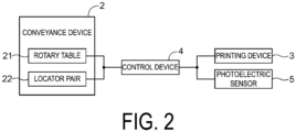
FIG. 2 is a block diagram illustrating components of the printing system according to the embodiment. -
FIG. 3 is a schematic view of a side surface illustrating an operation of a conveyance device according to the embodiment. -
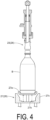
FIG. 4 is a diagram illustrating a variation of a locator pair. - An embodiment of a printing system according to the present invention will be described with reference to the drawings. Hereinafter, an example in which the printing system according to the present invention is applied to a
printing system 1 for performing laser printing on a PET bottle B (an example of a container) will be described. - The
printing system 1 according to the present embodiment includes aconveyance device 2, aprinting device 3, and a control device 4 (FIGS. 1 and2 ). Theprinting system 1 is generally a system configured to perform printing on the PET bottle B by theprinting device 3 when the PET bottle B being conveyed by theconveyance device 2 passes by theprinting device 3, and the operations of theconveyance device 2 and theprinting device 3 are cooperatively controlled by thecontrol device 4. - The
conveyance device 2 includes a rotary table 21 and a plurality oflocator pairs 22. The rotary table 21 is substantially circular in plan view. The plurality oflocator pairs 22 are mounted at equal intervals along the periphery of the rotary table 21, and are configured such that the PET bottle B can be held between anupper locator 23 and alower locator 24 constituting the locator pair 22 (this is an example of holding the top and bottom of the container). When the rotary table 21 rotates in a state in which the PET bottle B is held by thelocator pair 22, the PET bottle B is conveyed along a path (an example of a predetermined path) along the rotation track of the rotary table 21. Note that the rotation of the rotary table 21 is driven by a motor (not illustrated). - The
conveyance device 2 receives the PET bottle B from a wheel W1 in the previous process at areceiving position 2a. The received PET bottle B is conveyed along a path along the rotation track, and is subjected to printing by theprinting device 3 in a printing region A provided in the middle of the path. The PET bottle B on which the printing has been performed is discharged to a wheel W2 in the subsequent process at adischarge position 2b. - The
locator pair 22 is mounted on the rotary table 21 in such a manner that theupper locator 23 is mounted on an upper plate of the rotary table 21 and thelower locator 24 is mounted on a lower plate of the rotary table 21 (FIG. 3 ). Theupper locator 23 is configured such that acam follower 23a provided at the upper portion thereof travels on acam rail 25 built in the upper plate of the rotary table 21, and the vertical position of theupper locator 23 is determined by the position of theupper locator 23 in the circumferential direction. In a section S1 (FIGS. 1 and3 ), theupper locator 23 travels at the lower position, and a posture in which the PET bottle B can be held between theupper locator 23 and thelower locator 24 is realized. On the other hand, in a section S2 (FIGS. 1 and3 ), theupper locator 23 travels at the upper position to realize a posture in which the PET bottle B can be discharged or received. Thereceiving position 2a and thedischarge position 2b are located at both end portions of the section S2. - The
lower locator 24 includes asupport plate 24a for supporting the PET bottle B, aspring 24b attached to the lower side of thesupport plate 24a, and ahousing 24c for accommodating thesupport plate 24a and thespring 24b, and is configured to accommodate the bottom portion of the PET bottle B (FIG. 3 ). When the PET bottle B is interposed between theupper locator 23 and thelower locator 24 in the posture in which theupper locator 23 is lowered, the PET bottle B is held by the restoring force of aspring 23b of theupper locator 23 and thespring 24b of thelower locator 24. - Each locator pair 22 (the
upper locator 23 and the lower locator 24) is mounted on the rotary table 21 so as to be rotatable by a motor (not illustrated). Therefore, eachlocator pair 22 and the PET bottle B held by thelocator pair 22 can be rotated by the rotation of the rotary table 21 and rotated by the rotation of thelocator pair 22. Hereinafter, the rotational movement caused by the rotation of the rotary table 21 will be referred to as revolution, and the rotational movement caused by the rotation of thelocator pair 22 will be referred to as autorotation. - Note that a known device (such as an encoder) specifying the rotation angle of the rotary table 21 is provided, and a signal specifying the rotation angle is transmitted to the
control device 4. Like the rotation angle of the rotary table 21, a signal specifying the rotation angle of eachlocator pair 22 is also transmitted to thecontrol device 4. As a result, thecontrol device 4 can specify the position and autorotation angle of eachlocator pair 22 in the revolution track at any time. - The
conveyance device 2 having the above-described configuration may be mounted as a device conventionally used as a roll labeler. A known roll labeler realizes the application of a roll label to a container by a series of operations such as applying one end portion of the roll label to the container while conveying the container to which the roll label is to be attached along the revolution track and then winding the roll label around the container by autorotating the container, and a combination of a rotary table and a plurality of locator pairs is commonly used as a configuration of a roll labeler that can realize this series of operations. Therefore, generally the known roll labeler can be used as it is as theconveyance device 2 according to the present embodiment, or can be used after slight modification. - The
printing device 3 is a device that can draw a desired shape on a surface of a printing object by irradiating the printing object with a laser beam to cut, melt, evaporate, or the like the surface of the printing object. Theprinting device 3 itself can be implemented as a known device capable of realizing the above-described functions. Basic functions and performances (a light source, a wavelength, an output, and the like of laser beam) of theprinting device 3 as this type of printing device are not limited as long as printing can be performed on the PET bottle B. - The
printing device 3 is provided at a position near the path along the rotation track where laser printing can be performed on the PET bottle B being conveyed. More specifically, theprinting device 3 is installed such that the laser irradiation direction of theprinting device 3 faces the path and the focal point thereof at least partially overlaps with the path. A region in which a range where the laser beam can be irradiated with printable intensity by theprinting device 3 and the path of the PET bottle B overlap each other is a region in which printing can be performed on the PET bottle B by theprinting device 3, and is set as a printing region A. - Note that a
photoelectric sensor 5 is provided immediately in front of the printing region A (FIG. 1 ). When the PET bottle B passes through the detection range of thephotoelectric sensor 5, a signal is transmitted to thecontrol device 4. Thecontrol device 4 can recognize the entry of the PET bottle B into the printing region A based on this signal. - The
control device 4 is a device capable of controlling operations of theconveyance device 2 and theprinting device 3, and is implemented as, for example, a known computer. Signals for controlling the operations of theconveyance device 2 and theprinting device 3 are transmitted from thecontrol device 4 to theconveyance device 2 and theprinting device 3. Various signals indicating the operating states of theconveyance device 2 and theprinting device 3 are input to thecontrol device 4. Thecontrol device 4 can also present various information to the user and accept input of various information from the user. - Next, an embodiment of a printing method executed using the
printing system 1 according to the present embodiment will be described. As described above, in the printing method according to the present embodiment, the PET bottle B received by the printing system 1 (the conveyance device 2) is conveyed, the printing by theprinting device 3 is performed in the printing region A provided in the middle of the conveyance path, and the PET bottle B on which the printing has been performed is discharged in the subsequent process at thedischarge position 2b. - Since the rotation speed of the rotary table 21 (the revolution speed of the PET bottle B) is designated by external factors such as a desired production speed and the capability of previous and subsequent processes, it is difficult to freely set the rotation speed. On the other hand, since changing the rotation speed (autorotation speed of the PET bottle B) and the rotation amount (autorotation angle of the PET bottle B) of the
locator pair 22 does not affect the production speed and the previous and subsequent processes, the change can be freely set according to the convenience in printing. The rotation speed and the rotation amount of thelocator pair 22 can be set in accordance with various conditions such as the conveyance speed of the container accompanying the production speed, the shape of the container, and the printing amount on the printing surface. Therefore, in the printing method according to the present embodiment, the control function of controlling the rotation speed of thelocator pair 22 in accordance with the rotation speed of the rotary table 21 is executed by thecontrol device 4 in order to facilitate clear and precise printing. - Printing by the
printing device 3 is performed by an action mechanism in which a physical phenomenon such as cutting or melting is caused by applying thermal energy to a printing object by irradiating the printing object with a laser beam. For this reason, in order to appropriately perform printing, it is necessary to position the focal point of the laser beam as accurately as possible in a range of the PET bottle B where printing is desired. For this reason, the relative speed of the surface of the PET bottle B facing theprinting device 3 with respect to theprinting device 3 is preferably as low as possible. Therefore, in the control function, control is performed such that thelocator pair 22 is rotated in the direction opposite to the rotation direction of the rotary table 21 and the relative speed due to the revolution is partially canceled (suppressed) by the autorotation. For example, when the rotary table 21 rotates clockwise, thelocator pair 22 may be rotated counterclockwise (FIG. 1 ). Note that the rotation of thelocator pair 22 may be performed at least in the printing region A, and the presence or absence of the rotation in other regions on the path is arbitrary. - However, it is necessary to sweep the laser beam with respect to the PET bottle B in order to perform printing widely in the plane direction. When the
printing device 3 is moved for this sweeping, the laser beam itself may vibrate and interfere with focusing, and thus the PET bottle B should be moved. Therefore, the rotation speed of thelocator pair 22 is determined so that the relative speed of the surface of the PET bottle B facing theprinting device 3 with respect to theprinting device 3 becomes a speed suitable for the sweeping for printing. - Note that in the
printing system 1 according to the present embodiment, when printing is performed, the PET bottle B is held by thelocator pair 22, and the PET bottle B can be conveyed with less vibration. This also contributes to easy focusing of the laser beam on the PET bottle B. As a result, clear and precise printing can be performed as compared with the conventional printing system. Therefore, since relatively small characters and the like, which have been difficult to be printed in the conventional technique, can be clearly printed, items (for example, a raw material name, a business operator name, and the like) which are often printed in small characters in terms of commercial habits can be printed laser printing. - The
control device 4 also controls the start and stop of the rotation of the rotary table 21, the start and stop of the irradiation of the laser beam by theprinting device 3, and the like. - Finally, another embodiment of the printing system and the printing method according to the present invention will be described. Note that the configuration described in each of the following embodiments can also be applied in combination with the configuration described in another embodiment as long as no contradiction arises.
- As a variation, the lower locator of the locator pair may have a shape along the bottom portion of the container. For example, in a locator pair 26 (
FIG. 4 ) according to the variation, asupport plate 27a having a shape along the bottom portion of the PET bottle B is provided at alower locator 27. Ahousing 27c has a shape in which a wall surface on an inner side is cut out compared to thehousing 24c of thelower locator 24 according to the above-described embodiment so that asupport plate 27a can be accommodated when thesupport plate 27a is lowered. Note that aspring 27b is provided in the same manner as thelower locator 24 of the above-described embodiment, and the configuration of theupper locator 23 is also the same as that of the above-described embodiment. According to thelocator pair 26 of the variation, since the bottom portion of the PET bottle B is supported by thelower locator 27 not only downward but also laterally, the vibration of the PET bottle B being conveyed is further suppressed. - In the above-described embodiment, the configuration in which the
conveyance device 2 includes the rotary table 21 and the plurality of locator pairs 22 has been described as an example. However, the conveying device in the printing system according to the present invention is not limited as long as it can hold the top and bottom of the container and convey the held container along a predetermined path. Therefore, the conveyance path of the container is not limited to a path along the rotation track, and may be, for example, a linear path. - In the above-described embodiment, the configuration in which the
locator pair 22 is rotatably mounted on the rotary table 21 has been described as an example. However, in the present invention, the locator pair may be fixed relative to the conveyance device. - In the above-described embodiment, the configuration in which the
control device 4 controls the operations of theconveyance device 2 and theprinting device 3 has been described as an example. However, in the printing system according to the present invention, the control device may not be provided. For example, a configuration may be employed in which the conveyance speed of the conveyance device is set to a constant value and the rotation of the locator pair is mechanically regulated. - Also, with respect to other configurations, it should be understood that the embodiments described in the present specification are illustrative in all respects and that the scope of the present invention is not limited thereto. It will be easily understood by those skilled in the art that appropriate modifications can be made without departing from the spirit of the present invention. Accordingly, other embodiments modified without departing from the spirit of the present invention are naturally included in the scope of the present invention.
- The present invention is applicable to, for example, a printing system for applying printing on a PET bottle by laser.
-
- 1: Printing system
- 2: Conveyance device
- 2a: Receiving position
- 2b: Discharge position
- 3: Printing device
- 4: Control device
- 5: Photoelectric sensor
- 21: Rotary table
- 22: Locator pair
- 23: Upper locator
- 23a: Cam follower
- 23b: Spring
- 24: Lower locator
- 24a: Support plate
- 24b: Spring
- 24c: Housing
- 25: Cam rail
- 26: Locator pair (variation)
- 27: Lower locator (variation)
- 27a: Support plate (variation)
- 27b: Spring (variation)
- 27c: Housing (variation)
- A: Printing region
- B: PET bottle
Claims (7)
- A printing system comprising:a conveyance device configured to convey a container; anda printing device configured to perform laser printing on the container, whereinthe conveyance device is configured to hold top and bottom of the container and convey the container being held along a predetermined path, andthe printing device is provided at a position adjacent to the predetermined path where laser printing can be performed on the container being conveyed.
- The printing system according to claim 1, whereinthe conveyance device includes a rotary table being rotatable and a locator pair configured to hold the top and bottom of the container,the locator pair is mounted to a periphery of the rotary table, andthe predetermined path is a path along a rotation track of the rotary table.
- The printing system according to claim 2, wherein the locator pair is rotatably mounted to the rotary table.
- The printing system according to claim 3, further comprising a control device configured to independently control rotation of the rotary table and the locator pair.
- The printing system according to claim 4, whereinthe control device is capable of executing a control function of controlling a rotation speed of the locator pair in accordance with a rotation speed of the rotary table, andin the control function, the rotation speed of the locator pair is determined so as to suppress a relative speed with respect to the printing device of a surface, facing the printing device, of the container being conveyed in a state of being held by the locator pair.
- The printing system according to any one of claims 1 to 5, wherein the conveyance device is a roll labeler.
- A printing method comprising:
performing printing on a container held and conveyed by a conveying device by irradiating the container with a laser beam, the conveying device holding top and bottom of the container and conveying the held container along a predetermined path.
Applications Claiming Priority (2)
| Application Number | Priority Date | Filing Date | Title |
|---|---|---|---|
| JP2022095142A JP2023181798A (en) | 2022-06-13 | 2022-06-13 | Printing system and printing method |
| PCT/JP2023/021591 WO2023243567A1 (en) | 2022-06-13 | 2023-06-09 | Printing system and printing method |
Publications (2)
| Publication Number | Publication Date |
|---|---|
| EP4538188A1 true EP4538188A1 (en) | 2025-04-16 |
| EP4538188A4 EP4538188A4 (en) | 2026-06-10 |
Family
ID=89191276
Family Applications (1)
| Application Number | Title | Priority Date | Filing Date |
|---|---|---|---|
| EP23823857.0A Pending EP4538188A4 (en) | 2022-06-13 | 2023-06-09 | PRINTING SYSTEM AND PRINTING PROCESS |
Country Status (3)
| Country | Link |
|---|---|
| EP (1) | EP4538188A4 (en) |
| JP (1) | JP2023181798A (en) |
| WO (1) | WO2023243567A1 (en) |
Families Citing this family (1)
| Publication number | Priority date | Publication date | Assignee | Title |
|---|---|---|---|---|
| DE102024126815A1 (en) * | 2024-09-17 | 2026-03-19 | Khs Gmbh | Device and method for marking containers, machine for laser coding and system for manufacturing and/or treating containers |
Family Cites Families (9)
| Publication number | Priority date | Publication date | Assignee | Title |
|---|---|---|---|---|
| DE4237577A1 (en) * | 1991-11-10 | 1993-05-27 | A A A Software Consulting & Mf | Container re-filling code marking device - detects previously marked container code for positioning container relative to marking device to prevent codes overlapping |
| DE19739767C2 (en) * | 1997-09-10 | 2000-07-20 | Fribosa Ag Werkzeug Und Maschi | Labeling station for objects, such as bottles, with a marking device for the labels |
| JP2013212862A (en) | 2012-04-02 | 2013-10-17 | C I Kasei Co Ltd | Label attaching method for bottle |
| JP6307849B2 (en) | 2013-11-20 | 2018-04-11 | 東洋製罐株式会社 | Shrink label mounting method and mounting device therefor |
| CN103770994A (en) * | 2013-11-29 | 2014-05-07 | 青岛德隆科技有限公司 | Full automatic labeling code printing all-in-one machine |
| JP6260302B2 (en) * | 2014-01-29 | 2018-01-17 | シブヤマシナリー株式会社 | Label |
| CN210082679U (en) * | 2019-04-24 | 2020-02-18 | 广州南沙珠江啤酒有限公司 | Laser coding system for filling production line |
| JP7474570B2 (en) | 2019-07-17 | 2024-04-25 | アサヒ飲料株式会社 | Manufacturing method for beverage products packed in PET bottles, and PET bottle containers |
| EP3995249B1 (en) * | 2020-10-16 | 2024-04-17 | Ricoh Company, Ltd. | Pattern formation apparatus for base material and pattern formation method |
-
2022
- 2022-06-13 JP JP2022095142A patent/JP2023181798A/en active Pending
-
2023
- 2023-06-09 WO PCT/JP2023/021591 patent/WO2023243567A1/en not_active Ceased
- 2023-06-09 EP EP23823857.0A patent/EP4538188A4/en active Pending
Also Published As
| Publication number | Publication date |
|---|---|
| WO2023243567A1 (en) | 2023-12-21 |
| EP4538188A4 (en) | 2026-06-10 |
| JP2023181798A (en) | 2023-12-25 |
Similar Documents
| Publication | Publication Date | Title |
|---|---|---|
| RU2284952C2 (en) | Modules for labelers | |
| EP2875875A2 (en) | Plastic bottle processing apparatus and vehicle having same mounted thereon | |
| WO2023243567A1 (en) | Printing system and printing method | |
| EP3533720A1 (en) | Labelling machine and method for applying label sheets onto receptacles | |
| WO2017061556A1 (en) | Container supplying unit and automatic analysis device | |
| CN107640389A (en) | For the device for labeling to label containers and the method for operating this device for labeling | |
| US8537183B2 (en) | Printing device and data writing method thereof | |
| EP2367725B1 (en) | Machine for labeling by means of labels printed on a ribbon | |
| FR2648119B1 (en) | DEVICE FOR TRANSPORTING CONTAINERS, SUCH AS BOTTLES | |
| US8393369B2 (en) | Labeling machine for labels printed on continuous film | |
| CN103523309B (en) | Cutting mechanism with individual driver | |
| WO2017104524A1 (en) | Container supply unit and automatic analyzer | |
| CN105452107B (en) | Apparatus for applying adhesive tape provided on one surface without interruption around a group of two or more containers | |
| US7191576B2 (en) | Device for applying a prepared handle to a pack | |
| IT1311319B1 (en) | MACHINE FOR NON-DESTRUCTIVE INSPECTION OF CYLINDRICAL CONTAINERS FOR LIQUID PRODUCTS. | |
| CN102825918B (en) | Medium processing device | |
| CN210914094U (en) | Bottle cap conveying mechanism for gasket machine | |
| EP2658782B1 (en) | Labelling group | |
| KR100371985B1 (en) | Subsfrate cassette Unit | |
| KR20090114561A (en) | Scribing device and method, and substrate cutting device using same | |
| WO2025153308A1 (en) | Roll-fed labelling module with forming device | |
| SE9404444D0 (en) | Method and apparatus for sorting a container | |
| JP3332260B2 (en) | Paper double feed detector for automatic document issuing machine | |
| JPS61127404A (en) | Seal feeder in cup filler | |
| US20170113828A1 (en) | Method and device for labeling packages and containers |
Legal Events
| Date | Code | Title | Description |
|---|---|---|---|
| STAA | Information on the status of an ep patent application or granted ep patent |
Free format text: STATUS: THE INTERNATIONAL PUBLICATION HAS BEEN MADE |
|
| PUAI | Public reference made under article 153(3) epc to a published international application that has entered the european phase |
Free format text: ORIGINAL CODE: 0009012 |
|
| STAA | Information on the status of an ep patent application or granted ep patent |
Free format text: STATUS: REQUEST FOR EXAMINATION WAS MADE |
|
| 17P | Request for examination filed |
Effective date: 20250104 |
|
| AK | Designated contracting states |
Kind code of ref document: A1 Designated state(s): AL AT BE BG CH CY CZ DE DK EE ES FI FR GB GR HR HU IE IS IT LI LT LU LV MC ME MK MT NL NO PL PT RO RS SE SI SK SM TR |
|
| DAV | Request for validation of the european patent (deleted) | ||
| DAX | Request for extension of the european patent (deleted) | ||
| A4 | Supplementary search report drawn up and despatched |
Effective date: 20260511 |
|
| RIC1 | Information provided on ipc code assigned before grant |
Ipc: B65B 61/02 20060101AFI20260504BHEP Ipc: B41J 3/407 20060101ALI20260504BHEP Ipc: B41F 17/18 20060101ALI20260504BHEP Ipc: B41J 2/44 20060101ALI20260504BHEP |