EP4538183A2 - Control device for electric aircraft - Google Patents
Control device for electric aircraft Download PDFInfo
- Publication number
- EP4538183A2 EP4538183A2 EP25160513.5A EP25160513A EP4538183A2 EP 4538183 A2 EP4538183 A2 EP 4538183A2 EP 25160513 A EP25160513 A EP 25160513A EP 4538183 A2 EP4538183 A2 EP 4538183A2
- Authority
- EP
- European Patent Office
- Prior art keywords
- cleaning
- motor
- rotor
- control
- control apparatus
- Prior art date
- Legal status (The legal status is an assumption and is not a legal conclusion. Google has not performed a legal analysis and makes no representation as to the accuracy of the status listed.)
- Withdrawn
Links
Images



Classifications
-
- B—PERFORMING OPERATIONS; TRANSPORTING
- B64—AIRCRAFT; AVIATION; COSMONAUTICS
- B64C—AEROPLANES; HELICOPTERS
- B64C29/00—Aircraft capable of landing or taking-off vertically, e.g. vertical take-off and landing [VTOL] aircraft
- B64C29/0008—Aircraft capable of landing or taking-off vertically, e.g. vertical take-off and landing [VTOL] aircraft having its flight directional axis horizontal when grounded
- B64C29/0016—Aircraft capable of landing or taking-off vertically, e.g. vertical take-off and landing [VTOL] aircraft having its flight directional axis horizontal when grounded the lift during taking-off being created by free or ducted propellers or by blowers
-
- B—PERFORMING OPERATIONS; TRANSPORTING
- B08—CLEANING
- B08B—CLEANING IN GENERAL; PREVENTION OF FOULING IN GENERAL
- B08B1/00—Cleaning by methods involving the use of tools
- B08B1/10—Cleaning by methods involving the use of tools characterised by the type of cleaning tool
- B08B1/12—Brushes
-
- B—PERFORMING OPERATIONS; TRANSPORTING
- B08—CLEANING
- B08B—CLEANING IN GENERAL; PREVENTION OF FOULING IN GENERAL
- B08B1/00—Cleaning by methods involving the use of tools
- B08B1/20—Cleaning of moving articles, e.g. of moving webs or of objects on a conveyor
-
- B—PERFORMING OPERATIONS; TRANSPORTING
- B08—CLEANING
- B08B—CLEANING IN GENERAL; PREVENTION OF FOULING IN GENERAL
- B08B3/00—Cleaning by methods involving the use or presence of liquid or steam
- B08B3/02—Cleaning by the force of jets or sprays
- B08B3/022—Cleaning travelling work
-
- B—PERFORMING OPERATIONS; TRANSPORTING
- B60—VEHICLES IN GENERAL
- B60L—PROPULSION OF ELECTRICALLY-PROPELLED VEHICLES; SUPPLYING ELECTRIC POWER FOR AUXILIARY EQUIPMENT OF ELECTRICALLY-PROPELLED VEHICLES; ELECTRODYNAMIC BRAKE SYSTEMS FOR VEHICLES IN GENERAL; MAGNETIC SUSPENSION OR LEVITATION FOR VEHICLES; MONITORING OPERATING VARIABLES OF ELECTRICALLY-PROPELLED VEHICLES; ELECTRIC SAFETY DEVICES FOR ELECTRICALLY-PROPELLED VEHICLES
- B60L15/00—Methods, circuits, or devices for controlling the traction-motor speed of electrically-propelled vehicles
- B60L15/20—Methods, circuits, or devices for controlling the traction-motor speed of electrically-propelled vehicles for control of the vehicle or its driving motor to achieve a desired performance, e.g. speed, torque, programmed variation of speed
-
- B—PERFORMING OPERATIONS; TRANSPORTING
- B60—VEHICLES IN GENERAL
- B60L—PROPULSION OF ELECTRICALLY-PROPELLED VEHICLES; SUPPLYING ELECTRIC POWER FOR AUXILIARY EQUIPMENT OF ELECTRICALLY-PROPELLED VEHICLES; ELECTRODYNAMIC BRAKE SYSTEMS FOR VEHICLES IN GENERAL; MAGNETIC SUSPENSION OR LEVITATION FOR VEHICLES; MONITORING OPERATING VARIABLES OF ELECTRICALLY-PROPELLED VEHICLES; ELECTRIC SAFETY DEVICES FOR ELECTRICALLY-PROPELLED VEHICLES
- B60L3/00—Electric devices on electrically-propelled vehicles for safety purposes; Monitoring operating variables, e.g. speed, deceleration or energy consumption
- B60L3/0023—Detecting, eliminating, remedying or compensating for drive train abnormalities, e.g. failures within the drive train
- B60L3/0061—Detecting, eliminating, remedying or compensating for drive train abnormalities, e.g. failures within the drive train relating to electrical machines
-
- B—PERFORMING OPERATIONS; TRANSPORTING
- B60—VEHICLES IN GENERAL
- B60L—PROPULSION OF ELECTRICALLY-PROPELLED VEHICLES; SUPPLYING ELECTRIC POWER FOR AUXILIARY EQUIPMENT OF ELECTRICALLY-PROPELLED VEHICLES; ELECTRODYNAMIC BRAKE SYSTEMS FOR VEHICLES IN GENERAL; MAGNETIC SUSPENSION OR LEVITATION FOR VEHICLES; MONITORING OPERATING VARIABLES OF ELECTRICALLY-PROPELLED VEHICLES; ELECTRIC SAFETY DEVICES FOR ELECTRICALLY-PROPELLED VEHICLES
- B60L3/00—Electric devices on electrically-propelled vehicles for safety purposes; Monitoring operating variables, e.g. speed, deceleration or energy consumption
- B60L3/04—Cutting off the power supply under fault conditions
-
- B—PERFORMING OPERATIONS; TRANSPORTING
- B60—VEHICLES IN GENERAL
- B60L—PROPULSION OF ELECTRICALLY-PROPELLED VEHICLES; SUPPLYING ELECTRIC POWER FOR AUXILIARY EQUIPMENT OF ELECTRICALLY-PROPELLED VEHICLES; ELECTRODYNAMIC BRAKE SYSTEMS FOR VEHICLES IN GENERAL; MAGNETIC SUSPENSION OR LEVITATION FOR VEHICLES; MONITORING OPERATING VARIABLES OF ELECTRICALLY-PROPELLED VEHICLES; ELECTRIC SAFETY DEVICES FOR ELECTRICALLY-PROPELLED VEHICLES
- B60L3/00—Electric devices on electrically-propelled vehicles for safety purposes; Monitoring operating variables, e.g. speed, deceleration or energy consumption
- B60L3/12—Recording operating variables ; Monitoring of operating variables
-
- B—PERFORMING OPERATIONS; TRANSPORTING
- B64—AIRCRAFT; AVIATION; COSMONAUTICS
- B64D—EQUIPMENT FOR FITTING IN OR TO AIRCRAFT; FLIGHT SUITS; PARACHUTES; ARRANGEMENT OR MOUNTING OF POWER PLANTS OR PROPULSION TRANSMISSIONS IN AIRCRAFT
- B64D27/00—Arrangement or mounting of power plants in aircraft; Aircraft characterised by the type or position of power plants
- B64D27/02—Aircraft characterised by the type or position of power plants
- B64D27/30—Aircraft characterised by electric power plants
-
- B—PERFORMING OPERATIONS; TRANSPORTING
- B64—AIRCRAFT; AVIATION; COSMONAUTICS
- B64D—EQUIPMENT FOR FITTING IN OR TO AIRCRAFT; FLIGHT SUITS; PARACHUTES; ARRANGEMENT OR MOUNTING OF POWER PLANTS OR PROPULSION TRANSMISSIONS IN AIRCRAFT
- B64D27/00—Arrangement or mounting of power plants in aircraft; Aircraft characterised by the type or position of power plants
- B64D27/02—Aircraft characterised by the type or position of power plants
- B64D27/30—Aircraft characterised by electric power plants
- B64D27/34—All-electric aircraft
-
- B—PERFORMING OPERATIONS; TRANSPORTING
- B64—AIRCRAFT; AVIATION; COSMONAUTICS
- B64D—EQUIPMENT FOR FITTING IN OR TO AIRCRAFT; FLIGHT SUITS; PARACHUTES; ARRANGEMENT OR MOUNTING OF POWER PLANTS OR PROPULSION TRANSMISSIONS IN AIRCRAFT
- B64D31/00—Power plant control systems; Arrangement of power plant control systems in aircraft
- B64D31/02—Initiating means
-
- B—PERFORMING OPERATIONS; TRANSPORTING
- B64—AIRCRAFT; AVIATION; COSMONAUTICS
- B64D—EQUIPMENT FOR FITTING IN OR TO AIRCRAFT; FLIGHT SUITS; PARACHUTES; ARRANGEMENT OR MOUNTING OF POWER PLANTS OR PROPULSION TRANSMISSIONS IN AIRCRAFT
- B64D31/00—Power plant control systems; Arrangement of power plant control systems in aircraft
- B64D31/16—Power plant control systems; Arrangement of power plant control systems in aircraft for electric power plants
-
- B—PERFORMING OPERATIONS; TRANSPORTING
- B64—AIRCRAFT; AVIATION; COSMONAUTICS
- B64F—GROUND OR AIRCRAFT-CARRIER-DECK INSTALLATIONS SPECIALLY ADAPTED FOR USE IN CONNECTION WITH AIRCRAFT; DESIGNING, MANUFACTURING, ASSEMBLING, CLEANING, MAINTAINING OR REPAIRING AIRCRAFT, NOT OTHERWISE PROVIDED FOR; HANDLING, TRANSPORTING, TESTING OR INSPECTING AIRCRAFT COMPONENTS, NOT OTHERWISE PROVIDED FOR
- B64F5/00—Designing, manufacturing, assembling, cleaning, maintaining or repairing aircraft, not otherwise provided for; Handling, transporting, testing or inspecting aircraft components, not otherwise provided for
- B64F5/30—Cleaning aircraft
-
- G—PHYSICS
- G05—CONTROLLING; REGULATING
- G05D—SYSTEMS FOR CONTROLLING OR REGULATING NON-ELECTRIC VARIABLES
- G05D1/00—Control of position, course, altitude or attitude of land, water, air or space vehicles, e.g. using automatic pilots
- G05D1/10—Simultaneous control of position or course in three dimensions
- G05D1/101—Simultaneous control of position or course in three dimensions specially adapted for aircraft
-
- H—ELECTRICITY
- H02—GENERATION; CONVERSION OR DISTRIBUTION OF ELECTRIC POWER
- H02P—CONTROL OR REGULATION OF ELECTRIC MOTORS, ELECTRIC GENERATORS OR DYNAMO-ELECTRIC CONVERTERS; CONTROLLING TRANSFORMERS, REACTORS OR CHOKE COILS
- H02P29/00—Arrangements for regulating or controlling electric motors, appropriate for both AC and DC motors
- H02P29/02—Providing protection against overload without automatic interruption of supply
- H02P29/024—Detecting a fault condition, e.g. short circuit, locked rotor, open circuit or loss of load
-
- B—PERFORMING OPERATIONS; TRANSPORTING
- B08—CLEANING
- B08B—CLEANING IN GENERAL; PREVENTION OF FOULING IN GENERAL
- B08B2203/00—Details of cleaning machines or methods involving the use or presence of liquid or steam
- B08B2203/02—Details of machines or methods for cleaning by the force of jets or sprays
-
- B—PERFORMING OPERATIONS; TRANSPORTING
- B60—VEHICLES IN GENERAL
- B60L—PROPULSION OF ELECTRICALLY-PROPELLED VEHICLES; SUPPLYING ELECTRIC POWER FOR AUXILIARY EQUIPMENT OF ELECTRICALLY-PROPELLED VEHICLES; ELECTRODYNAMIC BRAKE SYSTEMS FOR VEHICLES IN GENERAL; MAGNETIC SUSPENSION OR LEVITATION FOR VEHICLES; MONITORING OPERATING VARIABLES OF ELECTRICALLY-PROPELLED VEHICLES; ELECTRIC SAFETY DEVICES FOR ELECTRICALLY-PROPELLED VEHICLES
- B60L2200/00—Type of vehicles
- B60L2200/10—Air crafts
-
- B—PERFORMING OPERATIONS; TRANSPORTING
- B60—VEHICLES IN GENERAL
- B60L—PROPULSION OF ELECTRICALLY-PROPELLED VEHICLES; SUPPLYING ELECTRIC POWER FOR AUXILIARY EQUIPMENT OF ELECTRICALLY-PROPELLED VEHICLES; ELECTRODYNAMIC BRAKE SYSTEMS FOR VEHICLES IN GENERAL; MAGNETIC SUSPENSION OR LEVITATION FOR VEHICLES; MONITORING OPERATING VARIABLES OF ELECTRICALLY-PROPELLED VEHICLES; ELECTRIC SAFETY DEVICES FOR ELECTRICALLY-PROPELLED VEHICLES
- B60L2240/00—Control parameters of input or output; Target parameters
- B60L2240/40—Drive Train control parameters
- B60L2240/42—Drive Train control parameters related to electric machines
- B60L2240/421—Speed
-
- B—PERFORMING OPERATIONS; TRANSPORTING
- B60—VEHICLES IN GENERAL
- B60L—PROPULSION OF ELECTRICALLY-PROPELLED VEHICLES; SUPPLYING ELECTRIC POWER FOR AUXILIARY EQUIPMENT OF ELECTRICALLY-PROPELLED VEHICLES; ELECTRODYNAMIC BRAKE SYSTEMS FOR VEHICLES IN GENERAL; MAGNETIC SUSPENSION OR LEVITATION FOR VEHICLES; MONITORING OPERATING VARIABLES OF ELECTRICALLY-PROPELLED VEHICLES; ELECTRIC SAFETY DEVICES FOR ELECTRICALLY-PROPELLED VEHICLES
- B60L2240/00—Control parameters of input or output; Target parameters
- B60L2240/40—Drive Train control parameters
- B60L2240/42—Drive Train control parameters related to electric machines
- B60L2240/423—Torque
-
- B—PERFORMING OPERATIONS; TRANSPORTING
- B60—VEHICLES IN GENERAL
- B60L—PROPULSION OF ELECTRICALLY-PROPELLED VEHICLES; SUPPLYING ELECTRIC POWER FOR AUXILIARY EQUIPMENT OF ELECTRICALLY-PROPELLED VEHICLES; ELECTRODYNAMIC BRAKE SYSTEMS FOR VEHICLES IN GENERAL; MAGNETIC SUSPENSION OR LEVITATION FOR VEHICLES; MONITORING OPERATING VARIABLES OF ELECTRICALLY-PROPELLED VEHICLES; ELECTRIC SAFETY DEVICES FOR ELECTRICALLY-PROPELLED VEHICLES
- B60L2240/00—Control parameters of input or output; Target parameters
- B60L2240/80—Time limits
-
- B—PERFORMING OPERATIONS; TRANSPORTING
- B60—VEHICLES IN GENERAL
- B60L—PROPULSION OF ELECTRICALLY-PROPELLED VEHICLES; SUPPLYING ELECTRIC POWER FOR AUXILIARY EQUIPMENT OF ELECTRICALLY-PROPELLED VEHICLES; ELECTRODYNAMIC BRAKE SYSTEMS FOR VEHICLES IN GENERAL; MAGNETIC SUSPENSION OR LEVITATION FOR VEHICLES; MONITORING OPERATING VARIABLES OF ELECTRICALLY-PROPELLED VEHICLES; ELECTRIC SAFETY DEVICES FOR ELECTRICALLY-PROPELLED VEHICLES
- B60L2270/00—Problem solutions or means not otherwise provided for
- B60L2270/10—Emission reduction
- B60L2270/14—Emission reduction of noise
-
- B—PERFORMING OPERATIONS; TRANSPORTING
- B64—AIRCRAFT; AVIATION; COSMONAUTICS
- B64C—AEROPLANES; HELICOPTERS
- B64C2220/00—Active noise reduction systems
-
- B—PERFORMING OPERATIONS; TRANSPORTING
- B64—AIRCRAFT; AVIATION; COSMONAUTICS
- B64C—AEROPLANES; HELICOPTERS
- B64C29/00—Aircraft capable of landing or taking-off vertically, e.g. vertical take-off and landing [VTOL] aircraft
- B64C29/0008—Aircraft capable of landing or taking-off vertically, e.g. vertical take-off and landing [VTOL] aircraft having its flight directional axis horizontal when grounded
-
- Y—GENERAL TAGGING OF NEW TECHNOLOGICAL DEVELOPMENTS; GENERAL TAGGING OF CROSS-SECTIONAL TECHNOLOGIES SPANNING OVER SEVERAL SECTIONS OF THE IPC; TECHNICAL SUBJECTS COVERED BY FORMER USPC CROSS-REFERENCE ART COLLECTIONS [XRACs] AND DIGESTS
- Y02—TECHNOLOGIES OR APPLICATIONS FOR MITIGATION OR ADAPTATION AGAINST CLIMATE CHANGE
- Y02T—CLIMATE CHANGE MITIGATION TECHNOLOGIES RELATED TO TRANSPORTATION
- Y02T50/00—Aeronautics or air transport
- Y02T50/60—Efficient propulsion technologies, e.g. for aircraft
Definitions
- the present disclosure relates to control apparatuses for electric aircrafts.
- Known cleaning systems for aircraft include a cleaning system disclosed in patent literature 1.
- the cleaning system for an engine mounted to a blade of an aircraft which is disclosed in patent literature 1, is configured to guide cleaning fluid to the engine while the engine is controlled to rotate at a predetermined rotational speed.
- the rotational speed of the engine is controlled to be substantially 20 percent of a predetermined reference rotational speed used during flight of the aircraft.
- Patent Literature 1 Japanese Patent Application Publication (translation of PCT application) NO. 2008-537583
- users desire a technology that can clean a rotor of an electric aircraft while preventing an excessive increase in noise.
- the present disclosure can be implemented by the following exemplary aspects.
- the control apparatus controls, in the cleaning motor-control mode, the drive motor such that the rotational frequency of the drive motor is lower than the predetermined human-audible frequency range, making it possible to clean the rotor of the electrical aircraft while preventing an excessive increase in noise due to rotation of the drive motor.
- Electric drive systems (EDS) 10 to each of which a control apparatus 19 according to an exemplary embodiment of the present invention has been applied, are installed in an electric vertical take-off and landing aircraft (eVTOL) 100 illustrated in Figs. 1 and 2 .
- the eVTOL 100 includes a plurality of rotors, i.e., rotor fans, 30, and each EDS 10 is provided for the corresponding rotor 30, and is configured to control the corresponding rotor 30.
- the eVTOL 100 is configured as an electrically-driven uncrewed aircraft that can land and take off vertically.
- the eVTOL 100 includes, in addition to the EDSs 10, an airframe 20, a battery 40, a converter 42, a distributor 44, an aircraft control apparatus 50, an aircraft communication unit 64, and an informing unit 66; these components 40, 42, 44, 50, 64, and 66 are illustrated in Fig. 3 .
- the aircraft control apparatus 50 is configured as a computer including an unillustrated central processing unit (CPU) and an aircraft storage 51.
- the aircraft storage 51 which includes a read only memory (ROM) and a random-access memory (RAM), stores one or more control programs.
- the CPU is configured to run the one or more control programs stored in the aircraft storage 51 to accordingly serve as an aircraft controller 52 that controls overall operations of the eVTOL 100.
- the eVTOL 100 includes, as its overall operations, vertical landing and taking-off operations and a flying operation.
- the eVTOL 100 can be configured to perform the vertical landing and taking-off operations and flying operation in accordance with information indicative of a previously scheduled air-route or instructions sent from an external controller 510 included in an external apparatus 500 described later.
- the aircraft controller 52 is configured to individually control a rotational angle of each rotor 30.
- the aircraft controller 52 is configured to instruct the control apparatus 19 to operate in a selected one of flying motor-control mode, a cleaning motor-control mode and a stop mode for controlling a drive motor 12 of a selected EDS 10.
- the flying mode represents a mode of controlling each drive motor 12 to thereby cause the eVTOL 100 to take a flight set forth above.
- the cleaning motor-control mode represents a mode of causing the drive motor 12 of the selected EDS 10 to clean the rotor 30 of the selected EDS 10
- the stop mode represents a mode of stopping the drive motor 12 of the selected EDS 10.
- the eVTOL 100 of the exemplary embodiment includes, as illustrated in Fig. 1 , four rotors 30 and corresponding four EDSs 10.
- Fig. 2 illustrates typical two of the four rotors 30 and corresponding typical two of the four EDSs
- Fig. 3 illustrates a typical one of the four rotors 30 and a corresponding typical one of the four EDSs 10.
- the airframe 20 constitutes the remaining portion of the eVTOL 100 from which the four rotors 30 and the four EDSs 10 have been removed.
- the airframe 20 is comprised of an airframe body 21, a support strut 22, four first support members 23, and four second support members 24.
- the airframe body 21 constitutes the fuselage of the eVTOL 100.
- the eVTOL 100 has a center of gravity CM and a body axis AX, and the airframe body 21 has a bilaterally symmetrical structure with respect to the body axis AX.
- the body axis AX of the eVTOL 100 according to the exemplary embodiment is defined as an axis that passes through the center of gravity CM and extends along a predetermined front-back direction of the eVTOL 100.
- the center of gravity CM of the eVTOL 100 is defined as the center of gravity of the eVTOL 100 with empty weight, such as no cargo.
- the eVTOL 100 includes an acceleration sensor 29 mounted to the airframe 21.
- the acceleration sensor 29 is configured as a three-axis acceleration sensor, and measures a degree of tilt of the eVTOL 100 with respect to each axis and/or vibrations related to the eVTOL 100.
- the measurement results by the acceleration sensor 29 are outputted therefrom to the aircraft control apparatus 50.
- Each of the four first support members 23 has a substantially rodlike outline.
- the first support members 23 are arranged circumferentially at regular intervals while respectively extending radially along a vertical plane perpendicular to the vertical direction.
- Each of the four second support members 24 has a substantially rodlike outline, and joins the respective second ends of a corresponding pair of adjacent first support members 23.
- Fig. 1 illustrates each second support member 24 as a straight line.
- Each of the four rotors 30 is, as illustrated in Fig. 1 , is mounted to the first end of the corresponding first support member 23, and is also mounted to ends of corresponding adjacent second support members 24; the ends of the corresponding adjacent second support members 24 are joined to the first end of the corresponding first support member 23.
- the four rotor 30 include two front rotors 30a and two rear rotors 30b.
- the front rotors 30a are located forward of the center of gravity CM of the eVTOL 100
- the rear rotors 30b are located to the rear of the center of gravity CM of the eVTOL 100.
- the four rotors 30 serve as both lifting rotors for lifting the airframe 20, and cruising rotors for causing the airframe 20 to cruise. Specifically, controlling all the four rotors 30 to have a predetermined rotational speed enables the four rotors 30 to serve as lifting rotors. Controlling the rotational speed of the front rotors 30a and that of the rear rotors 30b to be different from each other enables the four rotors 30 to serve as cruising rotors.
- the eVTOL 100 includes a rotational speed sensor 34 and a torque sensor 35 provided for each rotor 30.
- the rotational speed sensor 34 provided for each rotor 30 is configured to measure the rotational speed of the corresponding rotor 30.
- the torque sensor 35 provided for each rotor 30 is configured to measure rotating torque of the corresponding rotor 30.
- the measurement results by each rotational speed sensor 34 are outputted therefrom to the aircraft control apparatus 50, and the measurement results by each torque sensor 35 are outputted therefrom to the aircraft control apparatus 50.
- Each rotor 30 is connected to the corresponding EDS 10.
- Each EDS 10 connected to the corresponding rotor 30 is configured as an electrical drive system for rotatably driving the corresponding rotor 30. That is, each EDS 10 is configured to rotatably drive the corresponding rotor 30.
- Each EDS 10 includes, as illustrated in Fig. 3 , a driver 11, a drive motor 12, a gearbox 13, a rotational speed sensor 14, a current sensor 15, a voltage sensor 16, a torque sensor 17, and the control apparatus 19 described above.
- the driver 11 is configured as an electronic device comprised of an unillustrated inverter and a controller for controlling the inverter.
- the inverter is comprised of power switching devices, such as insulated gate bipolar transistors (IGBTs) and/or metal-oxide-semiconductor field-effect transistors (MOSFETs).
- IGBTs insulated gate bipolar transistors
- MOSFETs metal-oxide-semiconductor field-effect transistors
- the inverter is configured to supply, to the drive motor 12, a drive voltage that is determined based on a duty factor; the duty factor is specified by a control signal supplied from the controller.
- the controller of the driver 11 is electrically connected to the control apparatus 19, and is configured to supply the control signal to the inverter based on an instruction supplied from the control apparatus 19.
- the drive motor 12 is comprised of, for example, a brushless motor according to the exemplary embodiment.
- the drive motor 12 is configured to output, to the gearbox 13, rotating motion in accordance with the drive voltage and a drive current supplied from the inverter of the driver 11.
- the drive motor 12 can be comprised of any motor, such as an induction motor or a reluctance motor in place of the brushless motor.
- the gearbox 13 physically joins the drive motor 12 and the rotor 30 to each other.
- the gearbox 13, which is comprised of a plurality of gears, is configured to reduce the rotating motion supplied from the drive motor 12 to accordingly transfer the reduced rotating motion to the rotor 30.
- the gearbox 13 can be omitted, so that the rotary shaft of the rotor 30 can be directly coupled to the drive motor 12.
- the rotational speed sensor 14 and the torque sensor 17 are provided for the drive motor 12.
- the rotational speed sensor 14 is configured to measure the rotational speed of the drive motor 12.
- the torque sensor 17 is configured to measure rotating torque generated by the drive motor 12.
- the current sensor 15 and the voltage sensor 16 are arranged between the driver 11 and the drive motor 12.
- the current sensor 15 is configured to measure the drive current supplied from the driver 11 to the drive motor 12
- the voltage sensor 16 is configured to measure the drive voltage supplied from the driver 11 to the drive motor 12.
- the measurement results by each of the sensors 14 to 17 are outputted therefrom to the control apparatus 19 through the driver 11.
- the measurement-result retrieving unit 192 is configured to retrieve the measurement results including
- the normality determiner 193 is configured to determine, based on the measurement results retrieved by the measurement-result retrieving unit 192, whether there is an abnormal situation in the eVTOL 100. How the normality determiner 193 determines whether there is an abnormal situation in the eVTOL 100 will be described later.
- the cleaning instructor 194 is configured to instruct cleaning equipment 200 illustrated in Figs. 2 and 3 to perform a cleaning task for cleaning the rotors 30 in the cleaning motor-control mode.
- the cleaning instructor 194 is additionally configured to instruct the cleaning equipment 200 to stop the cleaning routine when it is determined that there is an abnormal situation in the eVTOL 100 during controlling of the drive motor 12 in the cleaning motor-control mode.
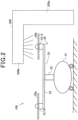
- the cleaning equipment 200 of the exemplary embodiment is comprised of, as illustrated in Fig. 2 , a first pole member 200a and a second pole member 200b.
- the first pole member 200a is located on the ground to extend in perpendicular to the ground.
- the second pole member 200b extends horizontally from the extending end of the first pole member 200a.
- the first and second pole members 200a and 200b are integrated with each other to have a substantially L shape.
- the first pole member 200a is configured such that its height relative to the ground is adjustable.
- the equipment communication unit 220 has a function of performing wireless communications with any device.
- the equipment communication unit 220 can communicate with the aircraft communication unit 64.
- the equipment communication unit 220 can use (i) commercial very high frequency (VHF) telecommunications, (ii) telecommunications, such as fourth-generation technology standard telecommunications (4G) or fifth-generation technology standard telecommunications (5G), provided by telecommunication cooperations, and/or (iii) wireless LAN communications in accordance with, for example, the IEEE 802,11 communications standard.
- the equipment communication unit 220 can use wired communications in accordance with the universal serial bus (USB) standard or the IEEE 802.3 communications standard.
- USB universal serial bus
- the cleaning equipment 200 is configured to execute cleaning of at least one of the rotors 30 in accordance with a cleaning program previously stored in the storage 19b.
- the cleaning program includes, for example, (i) a cleaning-fluid spraying phase, (ii) a brushing phase, and (iii) a drying phase.
- execution time setting for each of the cleaning-fluid spraying phase, brushing phase, and drying phase can be inputted from the external apparatus 500.
- the external apparatus 500 can be used a management/control computer for determining the execution time setting for each of the cleaning-fluid spraying phase, brushing phase, and drying phase.
- a management/control computer can be used a server arranged in, for example, an air-traffic control room or a personal computer brought into any place in the eVTOL 100 by a maintenance worker who performs maintenance, checking, and cleaning of the eVTOL 100.
- the cleaning equipment 200 sprays cleaning fluid from a predetermined portion of the existing end of the second pole member 200b to a selected rotor 30. Because the height of the first pole member 200a of the cleaning equipment 200 is adjustable, the height of the predetermined portion of the second pole member 200b can be adjusted to tailor the height of the selected rotor 30 located on the ground.
- the cleaning equipment 200 of the exemplary embodiment uses water as the cleaning fluid, but can use any type of cleaning chemicals in place of water.
- the height of the second pole member 200b of the cleaning equipment 200 is controlled so that one or more unillustrated brushes mounted to a surface of the existing end of the second pole member 200b, which faces the selected rotor 30, move. Thie results in the one or more brushes are fixedly positioned to abut onto the selected rotor 30. While the one or more brushes abut onto the selected rotor 30, the selected rotor 30 is controlled to rotate, so that the one or more brushes clean the selected rotor 30.
- the battery 40 is comprised of a lithium-ion battery, and serves as one power supply source in the eVTOL 100.
- the battery 40 is configured to mainly supply electrical power to the driver 11 included in each EDS 10 to accordingly drive, through the driver 11, the drive motor 12 of each EDS 10.
- the battery 40 can be comprised of any secondary battery, such as a nickel-metal-hydride battery in place of the lithium-ion battery.
- the eVTOL 100 can include, in addition to or in place of the battery 40, any power supply source, such as a fuel battery and/or a power generator.
- the converter 42 which is connected to the battery 40, is configured to step down a voltage across the battery 40 to accordingly supply the stepped-down voltage to unillustrated auxiliary devices and the aircraft control apparatus 50.
- the external apparatus 500 includes the external controller 510 set forth above and an external communication unit 520.
- the CPU 19a serves as the cleaning instructor 194 to instruct the cleaning equipment 200 to perform cleaning in accordance with the cleaning program previously stored in the storage 19b, so that the CPU 19a and/or the cleaning equipment 200 start execution of a rotor cleaning routine, which is illustrated in Fig. 4 , that cleans a selected rotor 30 of the eVTOL 100.
- the CPU 19a and/or the cleaning equipment 200 execute, as the rotor cleaning routine, the cleaning-fluid spraying phase, the brushing phase, and the drying phase while the eVTOL 100 is stopped on the ground.
- the CPU 19a serves as the measurement-result retrieving unit 192 to retrieve, from the rotational speed sensor 14, the rotational speed of the drive motor 12 as a measurement result by the rotational speed sensor 14 in step S14. Then, in step S14, the CPU 19a serves as the drive controller 191 to determine whether the rotational speed of the drive motor 12 measured by the rotational speed sensor 14 has reached a predetermined target rotational speed used for cleaning-fluid spraying.
- the rotor cleaning routine In response to determination that the rotational speed of the drive motor 12 has not reached the predetermined target rotational speed (NO in step S14), the rotor cleaning routine returns to the operation in step S12.
- the CPU 19a serves as the drive controller 191 to instruct the driver 11 to perform a normal rotating operation that rotates the drive motor 12 while maintaining the rotational speed of the drive motor 12 substantially at the target rotational speed in step S16.
- the CPU 19a serves as the drive controller 191 to determine whether a counted execution time of the cleaning-fluid spraying phase has reached the execution time setting for the cleaning-fluid spraying phase in step S18.
- the rotor cleaning routine returns to the operation in step S16.
- the CPU 19a serves as the drive controller 191 to instruct the driver 11 to reduce the rotational speed of the drive motor 12 in step S20.
- the CPU 19a serves as the drive controller 191 to determine whether the rotational speed of the drive motor 12 has reached zero in step S22. In response to determination that the rotational speed of the drive motor 12 has not reached zero (NO in step S22), the rotor cleaning routine returns to the operation in step S20.
- the CPU 19a serves as the drive controller 191 to determine whether all the cleaning-fluid spraying phase, brushing phase, and drying phase have been completely executed in step S24. At that time, because the brushing phase and the drying phase have not been executed yet (NO in step S24), the rotor cleaning routine returns to the operation in step S10.
- step S10 the CPU 19a receives the execution time setting for the brushing phase determined and sent from the external apparatus 500.
- the cleaning equipment 200 is controlled so that the one or more brushes of the cleaning equipment 200 move, and thereafter are fixedly positioned to abut onto the selected rotor 30.
- the CPU 19a serves as the drive controller 191 to instruct the driver 11 to rotate the selected rotor 30 and accelerate the rotational speed of the selected rotor 30 in step S12. While the rotational speed of the selected rotor 30 is accelerating, the rotating selected rotor 30 with water drops is cleaned by the one or more brushes.
- steps S14 to S22 for the brushing phase are carried out in the same manner as those for the cleaning-fluid spraying phase.
- the CPU 19a serves as the drive controller 191 to determine whether all the cleaning-fluid spraying phase, brushing phase, and drying phase have been completely executed in step S24. At that time, because the drying phase has not been executed yet (NO in step S24), the rotor cleaning routine returns to the operation in step S10.
- step S10 the CPU 19a receives the execution time setting for the drying phase determined and sent from the external apparatus 500.
- the CPU 19a serves as the drive controller 191 to instruct the driver 11 to rotate the selected rotor 30 and accelerate the rotational speed of the selected rotor 30 in step S12.
- the value of the target rotational speed used in the drying phase is higher than any other values of the target rotational speeds in the respective cleaning-fluid spraying phase and brushing phase, and the value of the target rotational speed used in the cleaning-fluid spraying phase is lower than any other values of the target rotational speeds in the respective brushing phase and dying phase.
- the value of the target rotational speed in the brushing phase is determined between the value of the target rotational speed used in the drying phase and the value of the target rotational speed in the cleaning-fluid spraying phase.
- the CPU 19a is programmed to execute, in step with start the rotor cleaning routine, an abnormal situation determination routine illustrated in Fig. 5 .
- the abnormal situation determination routine represents a routine of determining whether there is an abnormal situation in the eVTOL 100 during execution of the rotor cleaning routine.
- the abnormal situation determination routine aims to forestall the occurrence of an abnormal situation, for example, an abnormal cleaning situation of the rotor 30 by the cleaning equipment 200.
- the CPU 19a serves as the normality determiner 193 to determine, based on each measurement result of the rotational speed of the drive motor 12, whether an abnormal rotational speed is detected.
- the CPU 19a serves as the normality determiner 193 to determine whether each measurement result of the rotational speed of the drive motor 12 is within the predetermined allowable rotational-speed range to accordingly determine whether an abnormal rotational speed, which lies outside the predetermined allowable rotational-speed range, is detected.
- the CPU 19a In response to determination that an abnormal rotational speed is detected (YES in step S100), the CPU 19a stops the rotor cleaning routine illustrated in Fig. 4 in step S110, and thereafter terminates the abnormal situation determination routine.
- step S110 the CPU 19a changes the motor control mode from the cleaning motor-control mode to the stop mode
- step S100 the CPU 19a continues the cleaning motor-control mode in step S102. Additionally, in step S102, the CPU 19a serves as the normality determiner 193 to determine whether abnormal resistance is detected.
- the rotor (fan) 30 acts on the rotor (fan) 30 from the one or more brushes abutting onto the rotor 30 in the direction of stopping rotation of the rotor 30.
- This may result in a deviation between (i) a value of the target rotational speed to be controlled by the drive controller 191 through the driver 11 and (ii) a measured value of the rotational speed by the rotational speed sensor 34.
- the level of the deviation means resistance to rotation of the rotor 30.
- the abnormal resistance means the level of the deviation is outside a predetermined allowable resistance-level range.
- step S110 In response to determination that the level of the deviation is outside the predetermined allowable resistance-level range so that the abnormal resistance is detected (YES in step S102), the CPU 19a stops the rotor cleaning routine illustrated in Fig. 4 in step S110, and thereafter terminates the abnormal situation determination routine.
- the specific operation in step S110 in response to determination that the abnormal resistance is detected is substantially identical to that in response to determination that an abnormal rotational speed is detected, the specific operation in step S110 in response to determination that the abnormal resistance is detected.
- step S102 the CPU 19a continues the cleaning motor-control mode in step S104. Additionally, in step S104, the CPU 19a serves as the normality determiner 193 to determine whether abnormal vibrations are detected.
- the abnormal vibrations can include vibrations, which are caused by the airframe 20 of the eVTOL 100 and measured by the acceleration sensor 29, being outside a predetermined allowable vibration range defined during the cleaning task.
- the abnormal vibrations can include vibrations, which cause the airframe 20 to tilt at angles and are measured by the acceleration sensor 29; the angles of tilt of the airframe 20 being outside a predetermined allowable angular range defined during the cleaning task.
- step S104 In response to determination that abnormal vibrations are detected (YES in step S104), the CPU 19a stops the rotor cleaning routine illustrated in Fig. 4 in step S110, and thereafter terminates the abnormal situation determination routine.
- the specific operation in step S110 in response to determination that the abnormal resistance is detected is substantially identical to that in response to determination that an abnormal rotational speed is detected, the specific operation in step S110 in response to determination that the abnormal resistance is detected.
- step S104 the CPU 19a continues the cleaning motor-control mode in step S106. Additionally, in step S106, the CPU 19a serves as the normality determiner 193 to determine whether abnormal power is detected.
- the abnormal power means a power level calculated based on a measured value of the drive current by the current sensor 15 and a measured value of the drive voltage by the voltage sensor 16 being outside a predetermined allowable power-level range defined during the cleaning task.
- step S106 In response to determination that abnormal power is detected (YES in step S106), the CPU 19a stops the rotor cleaning routine illustrated in Fig. 4 in step S110, and thereafter terminates the abnormal situation determination routine.
- the specific operation in step S110 in response to determination that the abnormal resistance is detected is substantially identical to that in response to determination that an abnormal rotational speed is detected, the specific operation in step S110 in response to determination that the abnormal resistance is detected.
- step S106 the CPU 19a continues the cleaning motor-control mode in step S108. Additionally, in step S108, the CPU 19a serves as the drive controller 191 to determine whether the rotor cleaning routine illustrated in Fig. 4 has been completed. In response to determination that the rotor cleaning routine illustrated in Fig. 4 has not been completed yet (NO in step S108), the abnormal situation determination routine returns to step S100. Otherwise, in response to determination that the rotor cleaning routine illustrated in Fig. 4 has been completed (YES in step S108), the CPU 19a terminates the abnormal situation determination routine.
- the operation of changing the motor control mode from the cleaning motor-control mode to the stop mode in step S110 included in the abnormal situation determination routine can correspond to an operation of stopping the drive motor 12 in the claims described later.
- the control apparatus 19 of the exemplary embodiment described above is configured to control, in the cleaning motor-control mode, the rotational speed of the drive motor 12 such that the rotational frequency equivalent to the controlled rotational speed is lower than the predetermined human-audible frequency range. This configuration therefore makes it possible to clean the rotor 30 of the eVTOL 100 while preventing an excessive increase in noise due to rotation of the rotor 30.
- control apparatus 19 is configured to adjust the rotational frequency of the drive motor 12 of the rotor 30 to be lower than 20/A Hz where A represents a positive integer indicative of the number of blades of the rotor 30. This configuration therefore efficiently reduces noise whose level is based on the number of blades of the rotor 30.
- the control apparatus 19 includes the measurement-result retrieving unit 192 configured to retrieve, from, for example, each sensor 14, 15, 16, and 29, the corresponding measurement results, and the normality determiner 193 configured to determine, based on the retrieved measurement results, whether there is an abnormal situation in the eVTOL 100.
- the control apparatus 19 is configured to stop, in the cleaning motor-control mode, the cleaning task of the rotor 30 in response to determination that there is an abnormal situation in the eVTOL 100. This configuration therefore avoids the occurrence of an abnormal situation in the eVTOL 100 during cleaning the rotor 30
- the control apparatus 19 additionally includes the cleaning instructor 194 and the I/O interface 19c. This configuration makes it possible to send an instruction that instructs the cleaning equipment 200 to perform the cleaning task for cleaning the rotors 30.
- the control apparatus 19 is configured to control, in the cleaning motor-control mode, the drive motor 12 in accordance with the cleaning program previously stored in the storage 19b, making it possible to automatically perform each of the cleaning-fluid spraying phase, brushing phase, and drying phase of the cleaning task.
- the rotational frequency of the drive motor 12 according to the exemplary embodiment is controlled by the control apparatus 19 to be lower than 20/A Hz where A represents a positive integer indicative of the number of blades of the rotor 30, but the present disclosure is not limited thereto.
- the rotational frequency of the drive motor 12 according to the exemplary embodiment can be adjusted by the control apparatus 19 to a value lower than the predetermined human-audible frequency range.
- the measurement-result retrieving unit 192 of the control apparatus 19 is configured to retrieve the measurement results including
- the measurement-result retrieving unit 192 of the control apparatus 19 can be configured to retrieve a part of the measurement results.
- the cleaning instructor 194 of the control apparatus 19 is configured to send, to the cleaning equipment 200, one or more instructions that instruct the cleaning equipment 200 to perform (i) a cleaning-fluid spraying task, (ii) a brushing task, and (iii) a drying task. Additionally, the cleaning instructor 19 can be configured to send, to the cleaning equipment 200, one or more instructions that instruct the cleaning equipment 200 to perform other types of cleaning tasks. For example, the cleaning instructor 19 can send, to the cleaning equipment 200, a task of covering each rotor 30 with wax coating.
- the control apparatus 19 is installed in the eVTOL 100, but can be installed in any other types of electric aircrafts.
- the eVTOL 100 according to the exemplary embodiment which is configured as an uncrewed aircraft, but can be configured as a crewed aircraft.
- the control apparatus 19 is programmed to execute the abnormal situation determination routine, but can be programmed not to execute the abnormal situation determination routine.
- the control apparatus 19 is configured to control the drive motor 12 in one of the motor-control modes including at least three drive-motor control modes, such as the flying motor-control mode, the cleaning motor-control mode, and the stop mode, but can be configured control the drive motor 12 in any one of the flying motor-control mode and the cleaning motor-control mode.
- the control apparatus 19 can also be configured to control the drive motor 12 in any type control mode in addition to the flying motor-control mode, the cleaning motor-control mode, and the stop mode.
- control apparatus 19 can be configured to selectively control the drive motor 12 in at least one of the flying motor-control mode and the cleaning motor-control mode.
- the present disclosure is not limited to the above exemplary embodiment and the other embodiments and/or modifications, and can be implemented by various configurations within the scope of the present disclosure.
- technical features included in the above exemplary embodiment and the other embodiments and/or modifications which correspond to technical features included in exemplary measures described in the SUMMARY of the present disclosure, can be freely combined with each other or can be freely replaced with another feature in order to solve a part or all of the above issue and/or achieve a part or all of the above advantageous benefits.
- One or more of the technical features included in the above exemplary embodiment, which are not described as essential elements in the specification, can be deleted as necessity arises.
- control apparatuses and their control methods described in the present disclosure can be implemented by a dedicated computer including a memory and a processor programmed to perform one or more functions embodied by one or more computer programs.
- control apparatuses and their control methods described in the present disclosure can also be implemented by a dedicated computer including a processor comprised of one or more dedicated hardware logic circuits.
- control apparatuses and their control methods described in the present disclosure can further be implemented by a processor system comprised of a memory, a processor programmed to perform one or more functions embodied by one or more computer programs, and one or more hardware logic circuits.
- the one or more programs can be stored in a computer-readable non-transitory storage medium as instructions to be carried out by a computer or a processor.
- This application is a divisional application of European patent application no. 22 815 651.9 (the "parent application"), also published as EP 4 350 977 . Based on the original claims of the parent application, the following aspects form part of the content of this divisional application as filed.
Landscapes
- Engineering & Computer Science (AREA)
- Aviation & Aerospace Engineering (AREA)
- Transportation (AREA)
- Power Engineering (AREA)
- Mechanical Engineering (AREA)
- Life Sciences & Earth Sciences (AREA)
- Sustainable Development (AREA)
- Sustainable Energy (AREA)
- Manufacturing & Machinery (AREA)
- Radar, Positioning & Navigation (AREA)
- Remote Sensing (AREA)
- Physics & Mathematics (AREA)
- General Physics & Mathematics (AREA)
- Automation & Control Theory (AREA)
- Control Of Electric Motors In General (AREA)
- Nozzles For Electric Vacuum Cleaners (AREA)
- Manufacture Of Motors, Generators (AREA)
Abstract
Description
- This international application is based on and claims the benefit of priority from
Japanese Patent Application No. 2021-90953 filed on May 31, 2021 - The present disclosure relates to control apparatuses for electric aircrafts.
- Known cleaning systems for aircraft include a cleaning system disclosed in patent literature 1. The cleaning system for an engine mounted to a blade of an aircraft, which is disclosed in patent literature 1, is configured to guide cleaning fluid to the engine while the engine is controlled to rotate at a predetermined rotational speed. The rotational speed of the engine is controlled to be substantially 20 percent of a predetermined reference rotational speed used during flight of the aircraft.
- Patent Literature 1
Japanese Patent Application Publication (translation of PCT application) NO. 2008-537583 - The cleaning system disclosed in patent literature 1, which operates with the lower rotational speed of the engine, may not address noise due to the rotation of the engine.
- Let us assume that the cleaning system disclosed in the patent literature 1 is used to clean a rotor of an electric aircraft; the rotor is rotated by a motor of the electric aircraft. In this assumption, noise due to rotation of the motor may become a major issue. This may be because it is assumed that a place where such an electric aircraft is stored is located near houses and/or commercial facilities.
- From this viewpoint, users desire a technology that can clean a rotor of an electric aircraft while preventing an excessive increase in noise.
- The present disclosure can be implemented by the following exemplary aspects.
- The present disclosure provides control apparatuses for electrical aircrafts. Specifically, such a control apparatus according to an exemplary aspect of the present disclosure is used to control a drive motor that drives a rotor installed in an electrical aircraft. The control apparatus of the exemplary aspect is configured to instruct the drive motor to selectively operate in at least two motor-control modes. The at least two motor-control modes include a flying motor-control mode for causing the electrical aircraft to fly, and a cleaning motor-control mode for cleaning the rotor. The control apparatus of the exemplary aspect is configured to control, in the cleaning motor-control mode, the drive motor such that a rotational frequency of the drive motor is lower than a predetermined human-audible frequency range.
- The control apparatus according to the exemplary aspect controls, in the cleaning motor-control mode, the drive motor such that the rotational frequency of the drive motor is lower than the predetermined human-audible frequency range, making it possible to clean the rotor of the electrical aircraft while preventing an excessive increase in noise due to rotation of the drive motor.
- The above object, other objects, characteristics, and advantageous benefits of the present disclosure will become apparent from the following description with reference to the accompanying drawings in which:
-
Fig. 1 is a top plan view of an electric vertical take-off and landing aircraft, which schematically illustrates a configuration of the electric vertical take-off and landing aircraft in which a control apparatus according to an exemplary embodiment of the present disclosure has been installed; -
Fig. 2 is a side view of the electric vertical take-off and landing aircraft, which schematically illustrates how cleaning equipment sprays cleaning fluid to a rotor of the electric vertical take-off and landing aircraft; -
Fig. 3 is a block diagram illustrating a functional configuration of the electric vertical take-off and landing aircraft; -
Fig. 4 is a flowchart illustrating a procedure of a rotor cleaning routine; and -
Fig. 5 is a flowchart illustrating a procedure of an abnormal situation determination routine. - Electric drive systems (EDS) 10, to each of which a
control apparatus 19 according to an exemplary embodiment of the present invention has been applied, are installed in an electric vertical take-off and landing aircraft (eVTOL) 100 illustrated inFigs. 1 and2 . The eVTOL 100 includes a plurality of rotors, i.e., rotor fans, 30, and eachEDS 10 is provided for thecorresponding rotor 30, and is configured to control thecorresponding rotor 30. - The eVTOL 100 is configured as an electrically-driven uncrewed aircraft that can land and take off vertically. The eVTOL 100 includes, in addition to the
EDSs 10, anairframe 20, abattery 40, aconverter 42, adistributor 44, anaircraft control apparatus 50, anaircraft communication unit 64, and aninforming unit 66; thesecomponents Fig. 3 . - The
aircraft control apparatus 50 is configured as a computer including an unillustrated central processing unit (CPU) and anaircraft storage 51. Theaircraft storage 51, which includes a read only memory (ROM) and a random-access memory (RAM), stores one or more control programs. The CPU is configured to run the one or more control programs stored in theaircraft storage 51 to accordingly serve as anaircraft controller 52 that controls overall operations of the eVTOL 100. - The eVTOL 100 includes, as its overall operations, vertical landing and taking-off operations and a flying operation. The eVTOL 100 can be configured to perform the vertical landing and taking-off operations and flying operation in accordance with information indicative of a previously scheduled air-route or instructions sent from an external controller 510 included in an
external apparatus 500 described later. - The
aircraft controller 52 is configured to individually control a rotational angle of eachrotor 30. - Additionally, the
aircraft controller 52 is configured to instruct thecontrol apparatus 19 to operate in a selected one of flying motor-control mode, a cleaning motor-control mode and a stop mode for controlling adrive motor 12 of a selectedEDS 10. - The flying mode represents a mode of controlling each
drive motor 12 to thereby cause the eVTOL 100 to take a flight set forth above. - The cleaning motor-control mode represents a mode of causing the
drive motor 12 of theselected EDS 10 to clean therotor 30 of theselected EDS 10 - The stop mode represents a mode of stopping the
drive motor 12 of theselected EDS 10. - The eVTOL 100 of the exemplary embodiment includes, as illustrated in
Fig. 1 , fourrotors 30 and corresponding fourEDSs 10. For the sake of simply illustration,Fig. 2 illustrates typical two of the fourrotors 30 and corresponding typical two of the fourEDSs 10, andFig. 3 illustrates a typical one of the fourrotors 30 and a corresponding typical one of the fourEDSs 10. - The
airframe 20 constitutes the remaining portion of the eVTOL 100 from which the fourrotors 30 and the fourEDSs 10 have been removed. Theairframe 20 is comprised of anairframe body 21, asupport strut 22, fourfirst support members 23, and foursecond support members 24. - The
airframe body 21 constitutes the fuselage of the eVTOL 100. The eVTOL 100 has a center of gravity CM and a body axis AX, and theairframe body 21 has a bilaterally symmetrical structure with respect to the body axis AX. The body axis AX of the eVTOL 100 according to the exemplary embodiment is defined as an axis that passes through the center of gravity CM and extends along a predetermined front-back direction of theeVTOL 100. The center of gravity CM of the eVTOL 100 is defined as the center of gravity of the eVTOL 100 with empty weight, such as no cargo. - The eVTOL 100 includes an
acceleration sensor 29 mounted to theairframe 21. Theacceleration sensor 29 is configured as a three-axis acceleration sensor, and measures a degree of tilt of theeVTOL 100 with respect to each axis and/or vibrations related to theeVTOL 100. The measurement results by theacceleration sensor 29 are outputted therefrom to theaircraft control apparatus 50. - The
support strut 22 has a substantially pole-shaped outline, and is secured to the top of theairframe body 21. Thesupport strut 22 extends vertically with the eVTOL 100 being stopped on the ground. Thesupport strut 22 according to the exemplary embodiment is arranged to overlap the center of gravity CM of the eVTOL 100 when viewed in the vertical direction. Thesupport strut 22 has an upper end, and each of the fourfirst support members 23 has opposing first and second ends. The first end of eachfirst support member 23 is individually secured to the upper end of thesupport strut 22. - Each of the four
first support members 23 has a substantially rodlike outline. Thefirst support members 23 are arranged circumferentially at regular intervals while respectively extending radially along a vertical plane perpendicular to the vertical direction. To the second end of eachfirst support member 23, which is located farther from thesupport strut 22 than the first end is, thecorresponding rotor 30 and thecorresponding EDS 10 are mounted. - Each of the four
second support members 24 has a substantially rodlike outline, and joins the respective second ends of a corresponding pair of adjacentfirst support members 23. For the sake of simplifying illustration,Fig. 1 illustrates eachsecond support member 24 as a straight line. - Each of the four
rotors 30 is, as illustrated inFig. 1 , is mounted to the first end of the correspondingfirst support member 23, and is also mounted to ends of corresponding adjacentsecond support members 24; the ends of the corresponding adjacentsecond support members 24 are joined to the first end of the correspondingfirst support member 23. - The four
rotor 30 include twofront rotors 30a and tworear rotors 30b. Thefront rotors 30a are located forward of the center of gravity CM of theeVTOL 100, and therear rotors 30b are located to the rear of the center of gravity CM of theeVTOL 100. - The four
rotors 30 serve as both lifting rotors for lifting theairframe 20, and cruising rotors for causing theairframe 20 to cruise. Specifically, controlling all the fourrotors 30 to have a predetermined rotational speed enables the fourrotors 30 to serve as lifting rotors. Controlling the rotational speed of thefront rotors 30a and that of therear rotors 30b to be different from each other enables the fourrotors 30 to serve as cruising rotors. - Each
rotor 30 has a rotatory shaft, and is individually controlled to rotate together with the corresponding rotary shaft. - The
eVTOL 100 includes arotational speed sensor 34 and atorque sensor 35 provided for eachrotor 30. Therotational speed sensor 34 provided for eachrotor 30 is configured to measure the rotational speed of the correspondingrotor 30. Thetorque sensor 35 provided for eachrotor 30 is configured to measure rotating torque of the correspondingrotor 30. The measurement results by eachrotational speed sensor 34 are outputted therefrom to theaircraft control apparatus 50, and the measurement results by eachtorque sensor 35 are outputted therefrom to theaircraft control apparatus 50. Eachrotor 30 is connected to thecorresponding EDS 10. - Each
EDS 10 connected to the correspondingrotor 30 is configured as an electrical drive system for rotatably driving the correspondingrotor 30. That is, eachEDS 10 is configured to rotatably drive the correspondingrotor 30. - Each
EDS 10 includes, as illustrated inFig. 3 , adriver 11, adrive motor 12, agearbox 13, arotational speed sensor 14, acurrent sensor 15, avoltage sensor 16, atorque sensor 17, and thecontrol apparatus 19 described above. - The
driver 11 is configured as an electronic device comprised of an unillustrated inverter and a controller for controlling the inverter. The inverter is comprised of power switching devices, such as insulated gate bipolar transistors (IGBTs) and/or metal-oxide-semiconductor field-effect transistors (MOSFETs). The inverter is configured to supply, to thedrive motor 12, a drive voltage that is determined based on a duty factor; the duty factor is specified by a control signal supplied from the controller. The controller of thedriver 11 is electrically connected to thecontrol apparatus 19, and is configured to supply the control signal to the inverter based on an instruction supplied from thecontrol apparatus 19. - The
drive motor 12 is comprised of, for example, a brushless motor according to the exemplary embodiment. Thedrive motor 12 is configured to output, to thegearbox 13, rotating motion in accordance with the drive voltage and a drive current supplied from the inverter of thedriver 11. Thedrive motor 12 can be comprised of any motor, such as an induction motor or a reluctance motor in place of the brushless motor. - The
gearbox 13 physically joins thedrive motor 12 and therotor 30 to each other. Specifically, thegearbox 13, which is comprised of a plurality of gears, is configured to reduce the rotating motion supplied from thedrive motor 12 to accordingly transfer the reduced rotating motion to therotor 30. Thegearbox 13 can be omitted, so that the rotary shaft of therotor 30 can be directly coupled to thedrive motor 12. - The
rotational speed sensor 14 and thetorque sensor 17 are provided for thedrive motor 12. Therotational speed sensor 14 is configured to measure the rotational speed of thedrive motor 12. Thetorque sensor 17 is configured to measure rotating torque generated by thedrive motor 12. - The
current sensor 15 and thevoltage sensor 16 are arranged between thedriver 11 and thedrive motor 12. Thecurrent sensor 15 is configured to measure the drive current supplied from thedriver 11 to thedrive motor 12, and thevoltage sensor 16 is configured to measure the drive voltage supplied from thedriver 11 to thedrive motor 12. - The measurement results by each of the
sensors 14 to 17 are outputted therefrom to thecontrol apparatus 19 through thedriver 11. - The
control apparatus 19 provided for eachEDS 10 is configured as a computer comprised of aCPU 19a, astorage 19b, an input/output (I/O)interface 19c. - The
storage 19b stores one or more control programs. TheCPU 19a is configured to run the one or more control programs stored in thestorage 19b to function as adrive controller 191, a measurement-result retrieving unit 192, anormality determiner 193, and acleaning instructor 194. - The
drive controller 191 is configured to send, to thedriver 11, control instructions based on commanded values sent from theaircraft control apparatus 50 to accordingly rotatably drive the correspondingrotor 30. The commanded values include, for example, a commanded rotational speed for thedrive motor 12 in each of motor-control modes; the motor-control modes include a flying motor-control mode and a cleaning motor-control mode. - Specifically, the
drive controller 191 instructs, based on the commanded rotational speed for thedrive motor 12 in the cleaning motor-control mode, thedriver 11 to rotate thedrive motor 12 at a controlled rotational speed whose equivalent rotational frequency that is lower than a predetermined human-audible frequency range. For example, thedrive controller 191 instructs thedriver 11 to rotate thedrive motor 12 at a controlled rotational speed whose equivalent rotational frequency is lower than a predetermined human-audible frequency range. For example, thedrive controller 19 controls, through thedriver 11, thedrive motor 12 such that the frequency of rotation of thedrive motor 12 is lower than 20/A Hz where A represents a positive integer indicative of the number of blades of therotor 30. - The measurement-
result retrieving unit 192 is configured to retrieve the measurement results including - (I) The rotational speed of the
drive motor 12 from therotational speed sensor 14 - (II) Information on a rotating resistance related to the rotational speed of the corresponding
rotor 30 from therotational speed sensor 34 - (III) The drive current from the
current sensor 15 - (IV) The drive voltage from the
voltage sensor 16 - (V) The level of vibrations related to the
eVTOL 100 from theacceleration sensor 29 - (VI) The degree of tilt of the
eVTOL 100 from theacceleration sensor 29 - The
normality determiner 193 is configured to determine, based on the measurement results retrieved by the measurement-result retrieving unit 192, whether there is an abnormal situation in theeVTOL 100. How thenormality determiner 193 determines whether there is an abnormal situation in theeVTOL 100 will be described later. - The
cleaning instructor 194 is configured to instructcleaning equipment 200 illustrated inFigs. 2 and3 to perform a cleaning task for cleaning therotors 30 in the cleaning motor-control mode. - The
cleaning instructor 194 is additionally configured to instruct thecleaning equipment 200 to stop the cleaning routine when it is determined that there is an abnormal situation in theeVTOL 100 during controlling of thedrive motor 12 in the cleaning motor-control mode. - The
cleaning equipment 200 of the exemplary embodiment is comprised of, as illustrated inFig. 2 , afirst pole member 200a and asecond pole member 200b. Thefirst pole member 200a is located on the ground to extend in perpendicular to the ground. Thesecond pole member 200b extends horizontally from the extending end of thefirst pole member 200a. Specifically, the first andsecond pole members first pole member 200a is configured such that its height relative to the ground is adjustable. - The
cleaning equipment 200 includes, as illustrated inFig. 3 , aequipment controller 210 and anequipment communication unit 220. Theequipment controller 210 is configured to perform control of thecleaning equipment 200. Specifically, theequipment controller 210 performs control of at least thecleaning equipment 200 for spraying cleaning fluid, performing cleaning of any object using one or more brushes, and/or drying the cleaned object.Fig. 2 for example illustrates that thecleaning equipment 200 is spraying cleaning fluid to theeVTOL 100. - The
equipment communication unit 220 has a function of performing wireless communications with any device. For example, theequipment communication unit 220 can communicate with theaircraft communication unit 64. As the wireless communications, theequipment communication unit 220 can use (i) commercial very high frequency (VHF) telecommunications, (ii) telecommunications, such as fourth-generation technology standard telecommunications (4G) or fifth-generation technology standard telecommunications (5G), provided by telecommunication cooperations, and/or (iii) wireless LAN communications in accordance with, for example, theIEEE 802,11 communications standard. Theequipment communication unit 220 can use wired communications in accordance with the universal serial bus (USB) standard or the IEEE 802.3 communications standard. - The
cleaning equipment 200 is configured to execute cleaning of at least one of therotors 30 in accordance with a cleaning program previously stored in thestorage 19b. The cleaning program includes, for example, (i) a cleaning-fluid spraying phase, (ii) a brushing phase, and (iii) a drying phase. For example, execution time setting for each of the cleaning-fluid spraying phase, brushing phase, and drying phase can be inputted from theexternal apparatus 500. - As the
external apparatus 500, can be used a management/control computer for determining the execution time setting for each of the cleaning-fluid spraying phase, brushing phase, and drying phase. As such a management/control computer, can be used a server arranged in, for example, an air-traffic control room or a personal computer brought into any place in theeVTOL 100 by a maintenance worker who performs maintenance, checking, and cleaning of theeVTOL 100. - In accordance with the cleaning-fluid spraying phase of the cleaning program, the
cleaning equipment 200 sprays cleaning fluid from a predetermined portion of the existing end of thesecond pole member 200b to a selectedrotor 30. Because the height of thefirst pole member 200a of thecleaning equipment 200 is adjustable, the height of the predetermined portion of thesecond pole member 200b can be adjusted to tailor the height of the selectedrotor 30 located on the ground. Thecleaning equipment 200 of the exemplary embodiment uses water as the cleaning fluid, but can use any type of cleaning chemicals in place of water. - In accordance with the brushing phase of the cleaning program, the height of the
second pole member 200b of thecleaning equipment 200 is controlled so that one or more unillustrated brushes mounted to a surface of the existing end of thesecond pole member 200b, which faces the selectedrotor 30, move. Thie results in the one or more brushes are fixedly positioned to abut onto the selectedrotor 30. While the one or more brushes abut onto the selectedrotor 30, the selectedrotor 30 is controlled to rotate, so that the one or more brushes clean the selectedrotor 30. - In accordance with the drying phase of the cleaning program, the selected
rotor 30 is controlled to rotate at a predetermined rotational speed that is higher than that used in the brushing phase or the cleaning-fluid spraying phase. This rotation of the selectedrotor 30 removes droplets of water and dirt attached to the selectedrotor 30 from the selectedrotor 30. - The
storage 19b, which includes a ROM and a RAM, stores one or more control programs and the cleaning program. Thestorage 19b is additionally configured to store the measurement results sent from the sensors set forth above. - The I/
O interface 19c is configured to enable thecontrol apparatus 19 to communicate with external devices to thereby input and/or output various settings and/or values. The I/O interface 19c is configured to output instructions sent from instructions sent from thecleaning instructor 194 using wire communications or wireless communications to thecleaning equipment 200 through theaircraft communication unit 64. - The
battery 40 is comprised of a lithium-ion battery, and serves as one power supply source in theeVTOL 100. Thebattery 40 is configured to mainly supply electrical power to thedriver 11 included in eachEDS 10 to accordingly drive, through thedriver 11, thedrive motor 12 of eachEDS 10. Thebattery 40 can be comprised of any secondary battery, such as a nickel-metal-hydride battery in place of the lithium-ion battery. TheeVTOL 100 can include, in addition to or in place of thebattery 40, any power supply source, such as a fuel battery and/or a power generator. - The
converter 42, which is connected to thebattery 40, is configured to step down a voltage across thebattery 40 to accordingly supply the stepped-down voltage to unillustrated auxiliary devices and theaircraft control apparatus 50. - The
distributor 44 is configured to distribute the voltage across thebattery 42 to thedriver 11 of eachEDS 10. - The
external apparatus 500 includes the external controller 510 set forth above and anexternal communication unit 520. - The
aircraft communication unit 64 has a function of performing wireless communications with any device. For example, theaircraft communication unit 64 enables eachEDS 10 and theexternal communication unit 520 of theexternal apparatus 500 to communicate various information with each other, and enables eachEDS 10 and thecleaning equipment 200 to communicate various information with each other. Theaircraft communication unit 64 can communicate with theaircraft communication unit 52. As the wireless communications, theaircraft communication unit 64 can use (i) commercial very high frequency (VHF) telecommunications, (ii) telecommunications, such as fourth-generation technology standard telecommunications (4G) or fifth-generation technology standard telecommunications (5G), provided by telecommunication cooperations, and/or (iii) wireless LAN communications in accordance with, for example, theIEEE 802,11 communications standard. Theequipment communication unit 220 can use wired communications in accordance with the universal serial bus (USB) standard or the IEEE 802.3 communications standard. - The cleaning program according to the exemplary embodiment can serve as a motor-control program for cleaning recited in claims described later.
- The
CPU 19a serves as thecleaning instructor 194 to instruct thecleaning equipment 200 to perform cleaning in accordance with the cleaning program previously stored in thestorage 19b, so that theCPU 19a and/or thecleaning equipment 200 start execution of a rotor cleaning routine, which is illustrated inFig. 4 , that cleans a selectedrotor 30 of theeVTOL 100. Specifically, theCPU 19a and/or thecleaning equipment 200 execute, as the rotor cleaning routine, the cleaning-fluid spraying phase, the brushing phase, and the drying phase while theeVTOL 100 is stopped on the ground. - In step S10 of the rotor cleaning routine, the
CPU 19a receives the execution time setting for the cleaning-fluid spraying phase determined and sent from theexternal apparatus 500. Next, theCPU 19a serves as thedrive controller 191 to instruct thedriver 11 to rotate the selectedrotor 30 and accelerate the rotational speed of the selectedrotor 30 in step S12. After the operation in step S12, thecleaning equipment 200 is controlled to spray water as an example of cleaning fluid to therotating rotor 30. While the rotational speed of the selectedrotor 30 is accelerating, centrifugal force induced by the rotating selectedrotor 30 enables the sprayed water to reach every part of the selectedrotor 30 up to the outer periphery thereof. - Next, the
CPU 19a serves as the measurement-result retrieving unit 192 to retrieve, from therotational speed sensor 14, the rotational speed of thedrive motor 12 as a measurement result by therotational speed sensor 14 in step S14. Then, in step S14, theCPU 19a serves as thedrive controller 191 to determine whether the rotational speed of thedrive motor 12 measured by therotational speed sensor 14 has reached a predetermined target rotational speed used for cleaning-fluid spraying. - In response to determination that the rotational speed of the
drive motor 12 has not reached the predetermined target rotational speed (NO in step S14), the rotor cleaning routine returns to the operation in step S12. - Otherwise, in response to determination that the rotational speed of the
drive motor 12 has reached the predetermined target rotational speed (YES in step S14), theCPU 19a serves as thedrive controller 191 to instruct thedriver 11 to perform a normal rotating operation that rotates thedrive motor 12 while maintaining the rotational speed of thedrive motor 12 substantially at the target rotational speed in step S16. - Next, the
CPU 19a serves as thedrive controller 191 to determine whether a counted execution time of the cleaning-fluid spraying phase has reached the execution time setting for the cleaning-fluid spraying phase in step S18. In response to determination that the counted execution time of the cleaning-fluid spraying phase has not reached the execution time setting for the cleaning-fluid spraying phase (NO in step S18), the rotor cleaning routine returns to the operation in step S16. - Otherwise, in response to determination that the counted execution time of the cleaning-fluid spraying phase has reached the execution time setting for the cleaning-fluid spraying phase (YES in step S18), the
CPU 19a serves as thedrive controller 191 to instruct thedriver 11 to reduce the rotational speed of thedrive motor 12 in step S20. - Next, the
CPU 19a serves as thedrive controller 191 to determine whether the rotational speed of thedrive motor 12 has reached zero in step S22. In response to determination that the rotational speed of thedrive motor 12 has not reached zero (NO in step S22), the rotor cleaning routine returns to the operation in step S20. - Otherwise, in response to determination that the rotational speed of the
drive motor 12 has reached zero (YES in step S22), theCPU 19a serves as thedrive controller 191 to determine whether all the cleaning-fluid spraying phase, brushing phase, and drying phase have been completely executed in step S24. At that time, because the brushing phase and the drying phase have not been executed yet (NO in step S24), the rotor cleaning routine returns to the operation in step S10. - In step S10, the
CPU 19a receives the execution time setting for the brushing phase determined and sent from theexternal apparatus 500. After the operation in step S10, thecleaning equipment 200 is controlled so that the one or more brushes of thecleaning equipment 200 move, and thereafter are fixedly positioned to abut onto the selectedrotor 30. - Next, the
CPU 19a serves as thedrive controller 191 to instruct thedriver 11 to rotate the selectedrotor 30 and accelerate the rotational speed of the selectedrotor 30 in step S12. While the rotational speed of the selectedrotor 30 is accelerating, the rotating selectedrotor 30 with water drops is cleaned by the one or more brushes. - Thereafter, the operations in steps S14 to S22 for the brushing phase are carried out in the same manner as those for the cleaning-fluid spraying phase.
- In response to determination that the rotational speed of the
drive motor 12 has reached zero (YES in step S22), theCPU 19a serves as thedrive controller 191 to determine whether all the cleaning-fluid spraying phase, brushing phase, and drying phase have been completely executed in step S24. At that time, because the drying phase has not been executed yet (NO in step S24), the rotor cleaning routine returns to the operation in step S10. - In step S10, the
CPU 19a receives the execution time setting for the drying phase determined and sent from theexternal apparatus 500. - Next, the
CPU 19a serves as thedrive controller 191 to instruct thedriver 11 to rotate the selectedrotor 30 and accelerate the rotational speed of the selectedrotor 30 in step S12. - While the rotational speed of the selected
rotor 30 is accelerating, centrifugal force induced by the rotating selectedrotor 30 blows away dirty and/or water drops attached to the selectedrotor 30, thus drying the selectedrotor 30. - Thereafter, the operations in steps S14 to S22 for the drying phase are carried out in the same manner as those for the cleaning-fluid spraying phase.
- In response to determination that the rotational speed of the
drive motor 12 has reached zero (YES in step S22), theCPU 19a serves as thedrive controller 191 to determine whether all the cleaning-fluid spraying phase, brushing phase, and drying phase have been completely executed in step S24. At that time, because all the cleaning-fluid spraying phase, brushing phase, and drying phase have been completely executed (YES in step S24), theCPU 19a terminates the rotor cleaning routine. - The
drive controller 191 is, as described above, configured to control, through thedriver 11, the rotational speed of thedrive motor 12 in the cleaning motor-control mode to a target rotational speed whose equivalent rotational frequency is lower than the predetermined human-audible frequency range, that is, lower than 20/A Hz where A represents the positive integer indicative of the number of blades of therotor 30. In particular, thedrive controller 191 is configured to determine the target rotational speeds in the respective cleaning-fluid spraying, brushing, and drying phases to be different from one another. Optimum values used for the respective target rotational speeds depend on, for example, the radius of the rotor (fan) 30. For example, the value of the target rotational speed used in the drying phase is higher than any other values of the target rotational speeds in the respective cleaning-fluid spraying phase and brushing phase, and the value of the target rotational speed used in the cleaning-fluid spraying phase is lower than any other values of the target rotational speeds in the respective brushing phase and dying phase. The value of the target rotational speed in the brushing phase is determined between the value of the target rotational speed used in the drying phase and the value of the target rotational speed in the cleaning-fluid spraying phase. - The
CPU 19a is programmed to execute, in step with start the rotor cleaning routine, an abnormal situation determination routine illustrated inFig. 5 . The abnormal situation determination routine represents a routine of determining whether there is an abnormal situation in theeVTOL 100 during execution of the rotor cleaning routine. The abnormal situation determination routine aims to forestall the occurrence of an abnormal situation, for example, an abnormal cleaning situation of therotor 30 by thecleaning equipment 200. For example, the occurrence of an abnormal situation in theeVTOL 100 during execution of the rotor cleaning routine would result in, such as an abnormal cleaning situation of therotor 30, uncontrollable movement of therotor 30, which causes (i) the one or more brushes fixedly positioned in contact with therotor 30 to fly or (ii) theeVTOL 100 to be out of balance. - In step S100 of the abnormal situation determination routine, the
CPU 19a serves as thenormality determiner 193 to determine, based on each measurement result of the rotational speed of thedrive motor 12, whether an abnormal rotational speed is detected. For example, theCPU 19a serves as thenormality determiner 193 to determine whether each measurement result of the rotational speed of thedrive motor 12 is within the predetermined allowable rotational-speed range to accordingly determine whether an abnormal rotational speed, which lies outside the predetermined allowable rotational-speed range, is detected. - In response to determination that an abnormal rotational speed is detected (YES in step S100), the
CPU 19a stops the rotor cleaning routine illustrated inFig. 4 in step S110, and thereafter terminates the abnormal situation determination routine. - For example, in response to determination that an abnormal rotational speed is detected (YES in step S100), the
CPU 19a serves as - (I) The
cleaning instructor 194 to instruct thecleaning equipment 200 to stop execution of the cleaning task - (II) The
drive controller 191 to instruct thedriver 11 to deactivate thedrive motor 12 in step S110 - In step S110, the
CPU 19a changes the motor control mode from the cleaning motor-control mode to the stop mode - Otherwise, in response to determination that the rotational speed of the
drive motor 12 is within the allowable rotational-speed range, i.e., no abnormal rotational speed is detected (NO in step S100), theCPU 19a continues the cleaning motor-control mode in step S102. Additionally, in step S102, theCPU 19a serves as thenormality determiner 193 to determine whether abnormal resistance is detected. - Specifically, during execution of the cleaning task, force acts on the rotor (fan) 30 from the one or more brushes abutting onto the
rotor 30 in the direction of stopping rotation of therotor 30. This may result in a deviation between (i) a value of the target rotational speed to be controlled by thedrive controller 191 through thedriver 11 and (ii) a measured value of the rotational speed by therotational speed sensor 34. The level of the deviation means resistance to rotation of therotor 30. Additionally, the abnormal resistance means the level of the deviation is outside a predetermined allowable resistance-level range. - In response to determination that the level of the deviation is outside the predetermined allowable resistance-level range so that the abnormal resistance is detected (YES in step S102), the
CPU 19a stops the rotor cleaning routine illustrated inFig. 4 in step S110, and thereafter terminates the abnormal situation determination routine. The specific operation in step S110 in response to determination that the abnormal resistance is detected is substantially identical to that in response to determination that an abnormal rotational speed is detected, the specific operation in step S110 in response to determination that the abnormal resistance is detected. - Otherwise, in response to determination that the level of the deviation is within the predetermined allowable resistance-level range, i.e., no abnormal resistance is detected (NO in step S102), the
CPU 19a continues the cleaning motor-control mode in step S104. Additionally, in step S104, theCPU 19a serves as thenormality determiner 193 to determine whether abnormal vibrations are detected. - The abnormal vibrations can include vibrations, which are caused by the
airframe 20 of theeVTOL 100 and measured by theacceleration sensor 29, being outside a predetermined allowable vibration range defined during the cleaning task. - The abnormal vibrations can include vibrations, which cause the
airframe 20 to tilt at angles and are measured by theacceleration sensor 29; the angles of tilt of theairframe 20 being outside a predetermined allowable angular range defined during the cleaning task. - In response to determination that abnormal vibrations are detected (YES in step S104), the
CPU 19a stops the rotor cleaning routine illustrated inFig. 4 in step S110, and thereafter terminates the abnormal situation determination routine. The specific operation in step S110 in response to determination that the abnormal resistance is detected is substantially identical to that in response to determination that an abnormal rotational speed is detected, the specific operation in step S110 in response to determination that the abnormal resistance is detected. - Otherwise, in response to determination that no abnormal vibrations are detected (NO in step S104), the
CPU 19a continues the cleaning motor-control mode in step S106. Additionally, in step S106, theCPU 19a serves as thenormality determiner 193 to determine whether abnormal power is detected. - The abnormal power means a power level calculated based on a measured value of the drive current by the
current sensor 15 and a measured value of the drive voltage by thevoltage sensor 16 being outside a predetermined allowable power-level range defined during the cleaning task. - In response to determination that abnormal power is detected (YES in step S106), the
CPU 19a stops the rotor cleaning routine illustrated inFig. 4 in step S110, and thereafter terminates the abnormal situation determination routine. The specific operation in step S110 in response to determination that the abnormal resistance is detected is substantially identical to that in response to determination that an abnormal rotational speed is detected, the specific operation in step S110 in response to determination that the abnormal resistance is detected. - Otherwise, in response to determination that no abnormal power is detected (NO in step S106), the
CPU 19a continues the cleaning motor-control mode in step S108. Additionally, in step S108, theCPU 19a serves as thedrive controller 191 to determine whether the rotor cleaning routine illustrated inFig. 4 has been completed. In response to determination that the rotor cleaning routine illustrated inFig. 4 has not been completed yet (NO in step S108), the abnormal situation determination routine returns to step S100. Otherwise, in response to determination that the rotor cleaning routine illustrated inFig. 4 has been completed (YES in step S108), theCPU 19a terminates the abnormal situation determination routine. - The operation of changing the motor control mode from the cleaning motor-control mode to the stop mode in step S110 included in the abnormal situation determination routine can correspond to an operation of stopping the
drive motor 12 in the claims described later. - The
control apparatus 19 of the exemplary embodiment described above is configured to control, in the cleaning motor-control mode, the rotational speed of thedrive motor 12 such that the rotational frequency equivalent to the controlled rotational speed is lower than the predetermined human-audible frequency range. This configuration therefore makes it possible to clean therotor 30 of theeVTOL 100 while preventing an excessive increase in noise due to rotation of therotor 30. - Specifically, the
control apparatus 19 is configured to adjust the rotational frequency of thedrive motor 12 of therotor 30 to be lower than 20/A Hz where A represents a positive integer indicative of the number of blades of therotor 30. This configuration therefore efficiently reduces noise whose level is based on the number of blades of therotor 30. - The
control apparatus 19 includes the measurement-result retrieving unit 192 configured to retrieve, from, for example, eachsensor normality determiner 193 configured to determine, based on the retrieved measurement results, whether there is an abnormal situation in theeVTOL 100. Thecontrol apparatus 19 is configured to stop, in the cleaning motor-control mode, the cleaning task of therotor 30 in response to determination that there is an abnormal situation in theeVTOL 100. This configuration therefore avoids the occurrence of an abnormal situation in theeVTOL 100 during cleaning therotor 30 - The
control apparatus 19 additionally includes thecleaning instructor 194 and the I/O interface 19c. This configuration makes it possible to send an instruction that instructs thecleaning equipment 200 to perform the cleaning task for cleaning therotors 30. - The
control apparatus 19 is configured to control, in the cleaning motor-control mode, thedrive motor 12 in accordance with the cleaning program previously stored in thestorage 19b, making it possible to automatically perform each of the cleaning-fluid spraying phase, brushing phase, and drying phase of the cleaning task. - The rotational frequency of the
drive motor 12 according to the exemplary embodiment is controlled by thecontrol apparatus 19 to be lower than 20/A Hz where A represents a positive integer indicative of the number of blades of therotor 30, but the present disclosure is not limited thereto. Specifically, the rotational frequency of thedrive motor 12 according to the exemplary embodiment can be adjusted by thecontrol apparatus 19 to a value lower than the predetermined human-audible frequency range. - The measurement-
result retrieving unit 192 of thecontrol apparatus 19 according to the exemplary embodiment is configured to retrieve the measurement results including - (I) The rotational speed of the
drive motor 12 from therotational speed sensor 14 - (II) Information on a rotating resistance related to the rotational speed of the corresponding
rotor 30 from therotational speed sensor 34 - (III) The drive current from the
current sensor 15 - (IV) The drive voltage from the
voltage sensor 16 - (V) The level of vibrations related to the
eVTOL 100 from theacceleration sensor 29 - (VI) The degree of tilt of the
eVTOL 100 from theacceleration sensor 29 - The present disclosure is however not limited to this configuration. Specifically, the measurement-
result retrieving unit 192 of thecontrol apparatus 19 according to the exemplary embodiment can be configured to retrieve a part of the measurement results. - The
cleaning instructor 194 of thecontrol apparatus 19 according to the exemplary embodiment is configured to send, to thecleaning equipment 200, one or more instructions that instruct thecleaning equipment 200 to perform (i) a cleaning-fluid spraying task, (ii) a brushing task, and (iii) a drying task. Additionally, the cleaninginstructor 19 can be configured to send, to thecleaning equipment 200, one or more instructions that instruct thecleaning equipment 200 to perform other types of cleaning tasks. For example, the cleaninginstructor 19 can send, to thecleaning equipment 200, a task of covering eachrotor 30 with wax coating. - The
control apparatus 19 is configured to control, in the cleaning motor-control mode, thedrive motor 12 in accordance with the cleaning program previously stored in thestorage 19b, but the present disclosure is not limited thereto. Specifically, thecontrol apparatus 19 can be configured to control thedrive motor 12 in accordance with one or more instructions sent from any external apparatus, such as theexternal apparatus 500. - The
control apparatus 19 according to the exemplary embodiment is installed in theeVTOL 100, but can be installed in any other types of electric aircrafts. TheeVTOL 100 according to the exemplary embodiment, which is configured as an uncrewed aircraft, but can be configured as a crewed aircraft. - The
control apparatus 19 according to the exemplary embodiment is programmed to execute the abnormal situation determination routine, but can be programmed not to execute the abnormal situation determination routine. - The
control apparatus 19 according to the exemplary embodiment is configured to control thedrive motor 12 in one of the motor-control modes including at least three drive-motor control modes, such as the flying motor-control mode, the cleaning motor-control mode, and the stop mode, but can be configured control thedrive motor 12 in any one of the flying motor-control mode and the cleaning motor-control mode. Thecontrol apparatus 19 can also be configured to control thedrive motor 12 in any type control mode in addition to the flying motor-control mode, the cleaning motor-control mode, and the stop mode. - To sum up, it is preferable that the
control apparatus 19 according to the present disclosure can be configured to selectively control thedrive motor 12 in at least one of the flying motor-control mode and the cleaning motor-control mode. - The present disclosure is not limited to the above exemplary embodiment and the other embodiments and/or modifications, and can be implemented by various configurations within the scope of the present disclosure. For example, technical features included in the above exemplary embodiment and the other embodiments and/or modifications, which correspond to technical features included in exemplary measures described in the SUMMARY of the present disclosure, can be freely combined with each other or can be freely replaced with another feature in order to solve a part or all of the above issue and/or achieve a part or all of the above advantageous benefits. One or more of the technical features included in the above exemplary embodiment, which are not described as essential elements in the specification, can be deleted as necessity arises.
- The control apparatuses and their control methods described in the present disclosure can be implemented by a dedicated computer including a memory and a processor programmed to perform one or more functions embodied by one or more computer programs.
- The control apparatuses and their control methods described in the present disclosure can also be implemented by a dedicated computer including a processor comprised of one or more dedicated hardware logic circuits.
- The control apparatuses and their control methods described in the present disclosure can further be implemented by a processor system comprised of a memory, a processor programmed to perform one or more functions embodied by one or more computer programs, and one or more hardware logic circuits.
- The one or more programs can be stored in a computer-readable non-transitory storage medium as instructions to be carried out by a computer or a processor.
This application is a divisional application ofEuropean patent application no. 22 815 651.9 EP 4 350 977 . Based on the original claims of the parent application, the following aspects form part of the content of this divisional application as filed. - 1. A control apparatus (19) for controlling a drive motor (12) that drives a rotor (30) installed in an electrical aircraft, the control apparatus being configured to:
- instruct the drive motor to selectively operate in at least two motor-control modes that include:
- a flying motor-control mode for causing the electrical aircraft to fly; and
- a cleaning motor-control mode for cleaning the rotor; and
- control, in the cleaning motor-control mode, the drive motor such that a rotational frequency of the drive motor is lower than a predetermined human-audible frequency range.
- instruct the drive motor to selectively operate in at least two motor-control modes that include:
- 2. The control apparatus according to aspect 1, wherein:
the control apparatus is configured to control, in the cleaning motor-control mode, the drive motor such that the rotational frequency of the drive motor is lower than 20/A Hz where A represents a positive integer indicative of the number of blades of the rotor. - 3. The control apparatus according to aspect 1 or 2, further comprising:
- a measurement-result retrieving unit (192) configured to retrieve at least one of measurement results that include:
- a rotational speed of the drive motor;
- a rotating resistance related to the drive motor;
- a drive current related to the drive motor
- a drive voltage related to the drive motor
- a level of vibrations related to the electrical aircraft; and
- a degree of tilt of the electrical aircraft; and
- a normality determiner (193) configured to determine whether there is an abnormal situation in the electrical aircraft in accordance with the retrieved at least one of the measurement results,
- the at least two motor-control modes including a stop mode for stopping the drive motor,
- the control apparatus being configured to, in response to determination that there is an abnormal situation in the electrical aircraft during control of the drive motor in the cleaning motor-control mode, change the cleaning motor-control mode to the stop mode,
- the control apparatus being configured to, in response to determination that there are no abnormal situations in the electrical aircraft during control of the drive motor in the cleaning motor-control mode, continue the cleaning motor-control mode.
- a measurement-result retrieving unit (192) configured to retrieve at least one of measurement results that include:
- 4. The control apparatus according to any one of aspects 1 to 3, further comprising:
- a cleaning instructor (194) configured to send, to cleaning equipment, an instruction that instructs the cleaning equipment to perform a cleaning task for cleaning the rotor in the cleaning motor-control mode, the cleaning task including a task of spraying cleaning fluid, a brushing task, and a drying task; and
- an input/output interface (19c) configured to enable the control apparatus to communicate with one or more external devices using a wire communication or a wireless communication, so that the instruction is sent to the cleaning equipment through the input/output interface.
- 5. The control apparatus according to any one of aspects 1 to 4, wherein:
the control apparatus is configured to:- control, in the flying motor-control mode, the drive motor in accordance with a flying instruction sent from an aircraft control apparatus for controlling how the electrical aircraft flies; and
- control, in the cleaning motor-control mode, the drive motor in accordance with an externally sent instruction and/or a cleaning-motor control program previously stored in the control apparatus.
Claims (11)
- A control apparatus (19) for controlling a drive motor (12) that drives a rotor (30) installed in an electrical aircraft, the control apparatus being configured to:instruct the drive motor to selectively operate in at least two motor-control modes that include:wherein:a flying motor-control mode for causing the electrical aircraft to fly; anda cleaning motor-control mode for cleaning the rotor while the electrical aircraft is stopped on the ground,the cleaning motor-control mode includes:(i) a cleaning-fluid spraying phase for spraying cleaning fluid to the rotor of the electrical aircraft while the rotor is rotating at a predetermined first rotational frequency; and(ii) a drying phase for removing a droplet of fluid and dirt attached to the rotor using centrifugal force while the rotor is rotating at a predetermined second rotational frequency; andthe second rotational frequency in the drying phase is set to be different from the first rotational frequency in the cleaning-fluid spraying phase.
- The control apparatus according to claim 1, wherein:
the second rotational frequency in the drying phase is set to be higher than the first rotational frequency in the cleaning-fluid spraying phase. - The control apparatus according to claim 1, wherein:
the cleaning motor-control mode further includes:
a brushing phase for rotating the rotor at a predetermined third rotational frequency while a brush is positioned to abut onto the rotor to thereby clean the rotor. - The control apparatus according to claim 3, wherein:
the third rotational frequency in the brushing phase is set to be lower than the second rotational frequency in the drying phase. - The control apparatus according to claim 3, wherein:
the third rotational frequency in the brushing phase is set to be higher than the first rotational frequency in the cleaning-fluid spraying phase. - The control apparatus according to claim 3, wherein:
the third rotational frequency in the brushing phase is set to be higher than the first rotational frequency in the cleaning-fluid spraying phase and lower than the second rotational frequency in the drying phase. - The control apparatus according to any one of claims 1 to 6, wherein:
the second rotational frequency in the drying phase is set to be lower than 20/A Hz where A represents a positive integer indicative of the number of blades of the rotor. - The control apparatus according to any one of claims 1 to 7, further comprising:a measurement-result retrieving unit (192) configured to retrieve at least one of measurement results that include:a rotational speed of the drive motor;a rotating resistance related to the drive motor;a drive current related to the drive motora drive voltage related to the drive motora level of vibrations related to the electrical aircraft; anda degree of tilt of the electrical aircraft; anda normality determiner (193) configured to determine whether there is an abnormal situation in the electrical aircraft in accordance with the retrieved at least one of the measurement results.
- The control apparatus according to claim 8, wherein:the at least two motor-control modes include a stop mode for stopping the drive motor,the control apparatus being configured to, in response to determination that there is an abnormal situation in the electrical aircraft during control of the drive motor in the cleaning motor-control mode, change the cleaning motor-control mode to the stop mode,the control apparatus being configured to, in response to determination that there are no abnormal situations in the electrical aircraft during control of the drive motor in the cleaning motor-control mode, continue the cleaning motor-control mode.
- The control apparatus according to any one of claims 1 to 9, further comprising:a cleaning instructor (194) configured to send, to cleaning equipment, an instruction that instructs the cleaning equipment to perform a cleaning task for cleaning the rotor in the cleaning motor-control mode, the cleaning task including a task of spraying cleaning fluid, a brushing task, and a drying task; andan input/output interface (19c) configured to enable the control apparatus to communicate with one or more external devices using a wire communication or a wireless communication, so that the instruction is sent to the cleaning equipment through the input/output interface.
- The control apparatus according to any one of claims 1 to 10, wherein:
the control apparatus is configured to:control, in the flying motor-control mode, the drive motor in accordance with a flying instruction sent from an aircraft control apparatus for controlling how the electrical aircraft flies; andcontrol, in the cleaning motor-control mode, the drive motor in accordance with an externally sent instruction and/or a cleaning-motor control program previously stored in the control apparatus.
Applications Claiming Priority (3)
| Application Number | Priority Date | Filing Date | Title |
|---|---|---|---|
| JP2021090953A JP7484815B2 (en) | 2021-05-31 | 2021-05-31 | Electric aircraft control device |
| EP22815651.9A EP4350977B1 (en) | 2021-05-31 | 2022-03-23 | Control device for electric aircraft |
| PCT/JP2022/013467 WO2022254894A1 (en) | 2021-05-31 | 2022-03-23 | Control device for electric aircraft |
Related Parent Applications (2)
| Application Number | Title | Priority Date | Filing Date |
|---|---|---|---|
| EP22815651.9A Division-Into EP4350977B1 (en) | 2021-05-31 | 2022-03-23 | Control device for electric aircraft |
| EP22815651.9A Division EP4350977B1 (en) | 2021-05-31 | 2022-03-23 | Control device for electric aircraft |
Publications (2)
| Publication Number | Publication Date |
|---|---|
| EP4538183A2 true EP4538183A2 (en) | 2025-04-16 |
| EP4538183A3 EP4538183A3 (en) | 2025-05-07 |
Family
ID=84323005
Family Applications (2)
| Application Number | Title | Priority Date | Filing Date |
|---|---|---|---|
| EP25160513.5A Withdrawn EP4538183A3 (en) | 2021-05-31 | 2022-03-23 | Control device for electric aircraft |
| EP22815651.9A Active EP4350977B1 (en) | 2021-05-31 | 2022-03-23 | Control device for electric aircraft |
Family Applications After (1)
| Application Number | Title | Priority Date | Filing Date |
|---|---|---|---|
| EP22815651.9A Active EP4350977B1 (en) | 2021-05-31 | 2022-03-23 | Control device for electric aircraft |
Country Status (5)
| Country | Link |
|---|---|
| US (1) | US12612158B2 (en) |
| EP (2) | EP4538183A3 (en) |
| JP (1) | JP7484815B2 (en) |
| CN (1) | CN117426050A (en) |
| WO (1) | WO2022254894A1 (en) |
Families Citing this family (1)
| Publication number | Priority date | Publication date | Assignee | Title |
|---|---|---|---|---|
| JP7484815B2 (en) | 2021-05-31 | 2024-05-16 | 株式会社デンソー | Electric aircraft control device |
Citations (2)
| Publication number | Priority date | Publication date | Assignee | Title |
|---|---|---|---|---|
| JP2008537583A (en) | 2005-04-04 | 2008-09-18 | ユナイテッド テクノロジーズ コーポレイション | Mobile cleaning and water reclamation system for engines mounted on wings |
| EP4350977A1 (en) | 2021-05-31 | 2024-04-10 | Denso Corporation | Control device for electric aircraft |
Family Cites Families (14)
| Publication number | Priority date | Publication date | Assignee | Title |
|---|---|---|---|---|
| JP2002206499A (en) * | 2001-01-10 | 2002-07-26 | Minebea Co Ltd | Impeller for axial blower |
| US6503334B2 (en) * | 2001-03-14 | 2003-01-07 | Hydrochem Industrial Services, Inc. | Forced mist cleaning of combustion turbines |
| US20090120461A1 (en) * | 2004-01-30 | 2009-05-14 | Raymond Ford Johnson | Aircraft Rinse System |
| CN1788143B (en) | 2004-06-14 | 2011-07-06 | 燃气涡轮效率股份有限公司 | System and apparatus for collecting and treating wastewater from engine cleaning |
| FR2979615B1 (en) * | 2011-09-04 | 2013-09-20 | Eric Chantriaux | AIRCRAFT EQUIPPED WITH AN ELECTROMOTEUR GROUP DISTRIBUTED TO FREE WHEELS. |
| US11235893B2 (en) * | 2013-12-05 | 2022-02-01 | The Boeing Company | End effector for cleaning objects having multiple surfaces |
| US9739168B2 (en) * | 2014-06-05 | 2017-08-22 | General Electric Company | Off-line wash systems and methods for a gas turbine engine |
| DE102015117227A1 (en) | 2015-10-09 | 2017-04-13 | Valeo Schalter Und Sensoren Gmbh | Device for a motor vehicle for holding an unmanned aerial vehicle and motor vehicle |
| CN107804476A (en) * | 2017-10-31 | 2018-03-16 | 河南飞防兵科技有限公司 | A kind of unmanned plane shell cleaning device |
| US12269586B2 (en) * | 2018-06-15 | 2025-04-08 | The Texas A&M University System | Hover-capable aircraft |
| JP2021030931A (en) | 2019-08-27 | 2021-03-01 | 株式会社デンソー | Electric vertical take-off and landing aircraft and control device |
| CN110525232B (en) * | 2019-09-04 | 2024-05-28 | 天津易鼎丰动力科技有限公司 | Power system domain controller for electric automobile and control method thereof |
| US11455894B2 (en) | 2019-10-28 | 2022-09-27 | Skydio, Inc. | Structure scan using unmanned aerial vehicle |
| US11685524B2 (en) * | 2020-12-01 | 2023-06-27 | Textron Innovations Inc. | Rotorcraft quiet modes |
-
2021
- 2021-05-31 JP JP2021090953A patent/JP7484815B2/en active Active
-
2022
- 2022-03-23 EP EP25160513.5A patent/EP4538183A3/en not_active Withdrawn
- 2022-03-23 EP EP22815651.9A patent/EP4350977B1/en active Active
- 2022-03-23 WO PCT/JP2022/013467 patent/WO2022254894A1/en not_active Ceased
- 2022-03-23 CN CN202280038754.9A patent/CN117426050A/en active Pending
-
2023
- 2023-11-29 US US18/522,792 patent/US12612158B2/en active Active
Patent Citations (2)
| Publication number | Priority date | Publication date | Assignee | Title |
|---|---|---|---|---|
| JP2008537583A (en) | 2005-04-04 | 2008-09-18 | ユナイテッド テクノロジーズ コーポレイション | Mobile cleaning and water reclamation system for engines mounted on wings |
| EP4350977A1 (en) | 2021-05-31 | 2024-04-10 | Denso Corporation | Control device for electric aircraft |
Also Published As
| Publication number | Publication date |
|---|---|
| CN117426050A (en) | 2024-01-19 |
| JP7484815B2 (en) | 2024-05-16 |
| US12612158B2 (en) | 2026-04-28 |
| EP4350977A4 (en) | 2024-05-29 |
| EP4350977B1 (en) | 2025-05-07 |
| EP4538183A3 (en) | 2025-05-07 |
| US20240092183A1 (en) | 2024-03-21 |
| EP4350977A1 (en) | 2024-04-10 |
| WO2022254894A1 (en) | 2022-12-08 |
| JP2022183567A (en) | 2022-12-13 |
Similar Documents
| Publication | Publication Date | Title |
|---|---|---|
| US10035604B2 (en) | Vertical take-off and landing aircraft using hybrid-electric propulsion system | |
| US20210114727A1 (en) | In-flight battery recharging system for an unmanned aerial vehicle | |
| US12612158B2 (en) | Control apparatus for electric aircraft | |
| JP2016088111A (en) | helicopter | |
| EP3254963A1 (en) | Anti-torque control using matrix of fixed blade pitch motor modules | |
| JP7501494B2 (en) | Flight control device and flight control program | |
| EP3372496A1 (en) | Flying object | |
| JP2023069461A5 (en) | Flight control device and flight control program | |
| US20230030399A1 (en) | Multicopter and method for driving same | |
| US20240272652A1 (en) | Control device for vertical takeoff and landing aircraft | |
| JP2022045996A (en) | Helicopter | |
| CN109263874A (en) | A kind of oil electric mixed dynamic multi-rotor aerocraft | |
| CN107176298B (en) | Aircraft flight control method and aircraft | |
| US20250249791A1 (en) | Monitor, controller, operation management system, and storage medium | |
| JP2021030967A (en) | Control device for electric vertical take-off and landing aircraft and electric vertical take-off and landing aircraft | |
| JP2023104324A5 (en) | Vertical takeoff and landing aircraft control device and control program | |
| CN118405262A (en) | Power system of tilting hybrid fixed wing aircraft and control method thereof | |
| CN208498807U (en) | A kind of oil electric mixed dynamic unmanned vehicle | |
| JP2022183567A5 (en) | ||
| EP4712299A1 (en) | Balancing and measuring circuit for high voltage systems | |
| CN121269100B (en) | Propeller deicing device, deicing control method and aircraft | |
| US12528367B2 (en) | Charging control system, charging control method and aircraft | |
| US12589864B2 (en) | Control device for electric flight vehicle and non-transitory computer readable medium storing computer program for electric flight vehicle | |
| EP4695106A1 (en) | Systems and methods for electric damping of aircraft flight control surfaces and propellers | |
| WO2024253087A1 (en) | Propulsion system, propulsion control device, and propulsion control program |
Legal Events
| Date | Code | Title | Description |
|---|---|---|---|
| PUAI | Public reference made under article 153(3) epc to a published international application that has entered the european phase |
Free format text: ORIGINAL CODE: 0009012 |
|
| STAA | Information on the status of an ep patent application or granted ep patent |
Free format text: STATUS: REQUEST FOR EXAMINATION WAS MADE |
|
| REG | Reference to a national code |
Ref country code: DE Ref legal event code: R079 Free format text: PREVIOUS MAIN CLASS: B64F0005300000 Ipc: H02P0029000000 |
|
| PUAL | Search report despatched |
Free format text: ORIGINAL CODE: 0009013 |
|
| 17P | Request for examination filed |
Effective date: 20250227 |
|
| AC | Divisional application: reference to earlier application |
Ref document number: 4350977 Country of ref document: EP Kind code of ref document: P |
|
| AK | Designated contracting states |
Kind code of ref document: A2 Designated state(s): AL AT BE BG CH CY CZ DE DK EE ES FI FR GB GR HR HU IE IS IT LI LT LU LV MC MK MT NL NO PL PT RO RS SE SI SK SM TR |
|
| STAA | Information on the status of an ep patent application or granted ep patent |
Free format text: STATUS: EXAMINATION IS IN PROGRESS |
|
| AK | Designated contracting states |
Kind code of ref document: A3 Designated state(s): AL AT BE BG CH CY CZ DE DK EE ES FI FR GB GR HR HU IE IS IT LI LT LU LV MC MK MT NL NO PL PT RO RS SE SI SK SM TR |
|
| RIC1 | Information provided on ipc code assigned before grant |
Ipc: B64F 5/30 20170101ALI20250401BHEP Ipc: B64D 27/30 20240101ALI20250401BHEP Ipc: B64C 29/00 20060101ALI20250401BHEP Ipc: B64C 27/04 20060101ALI20250401BHEP Ipc: H02P 29/00 20160101AFI20250401BHEP |
|
| 17Q | First examination report despatched |
Effective date: 20250416 |
|
| STAA | Information on the status of an ep patent application or granted ep patent |
Free format text: STATUS: THE APPLICATION HAS BEEN WITHDRAWN |
|
| 18W | Application withdrawn |
Effective date: 20250520 |