EP4538165A1 - Autonomous unmanned underwater vehicle - Google Patents
Autonomous unmanned underwater vehicle Download PDFInfo
- Publication number
- EP4538165A1 EP4538165A1 EP23819713.1A EP23819713A EP4538165A1 EP 4538165 A1 EP4538165 A1 EP 4538165A1 EP 23819713 A EP23819713 A EP 23819713A EP 4538165 A1 EP4538165 A1 EP 4538165A1
- Authority
- EP
- European Patent Office
- Prior art keywords
- electric field
- underwater
- underwater vehicle
- potential sensor
- control circuitry
- Prior art date
- Legal status (The legal status is an assumption and is not a legal conclusion. Google has not performed a legal analysis and makes no representation as to the accuracy of the status listed.)
- Pending
Links
Images


Classifications
-
- B—PERFORMING OPERATIONS; TRANSPORTING
- B63—SHIPS OR OTHER WATERBORNE VESSELS; RELATED EQUIPMENT
- B63C—LAUNCHING, HAULING-OUT, OR DRY-DOCKING OF VESSELS; LIFE-SAVING IN WATER; EQUIPMENT FOR DWELLING OR WORKING UNDER WATER; MEANS FOR SALVAGING OR SEARCHING FOR UNDERWATER OBJECTS
- B63C11/00—Equipment for dwelling or working underwater; Means for searching for underwater objects
- B63C11/52—Tools specially adapted for working underwater, not otherwise provided for
-
- G—PHYSICS
- G01—MEASURING; TESTING
- G01N—INVESTIGATING OR ANALYSING MATERIALS BY DETERMINING THEIR CHEMICAL OR PHYSICAL PROPERTIES
- G01N27/00—Investigating or analysing materials by the use of electric, electrochemical, or magnetic means
- G01N27/60—Investigating or analysing materials by the use of electric, electrochemical, or magnetic means by investigating electrostatic variables, e.g. electrographic flaw testing
-
- B—PERFORMING OPERATIONS; TRANSPORTING
- B63—SHIPS OR OTHER WATERBORNE VESSELS; RELATED EQUIPMENT
- B63G—OFFENSIVE OR DEFENSIVE ARRANGEMENTS ON VESSELS; MINE-LAYING; MINE-SWEEPING; SUBMARINES; AIRCRAFT CARRIERS
- B63G8/00—Underwater vessels, e.g. submarines; Equipment specially adapted therefor
- B63G8/001—Underwater vessels adapted for special purposes, e.g. unmanned underwater vessels; Equipment specially adapted therefor, e.g. docking stations
-
- C—CHEMISTRY; METALLURGY
- C23—COATING METALLIC MATERIAL; COATING MATERIAL WITH METALLIC MATERIAL; CHEMICAL SURFACE TREATMENT; DIFFUSION TREATMENT OF METALLIC MATERIAL; COATING BY VACUUM EVAPORATION, BY SPUTTERING, BY ION IMPLANTATION OR BY CHEMICAL VAPOUR DEPOSITION, IN GENERAL; INHIBITING CORROSION OF METALLIC MATERIAL OR INCRUSTATION IN GENERAL
- C23F—NON-MECHANICAL REMOVAL OF METALLIC MATERIAL FROM SURFACE; INHIBITING CORROSION OF METALLIC MATERIAL OR INCRUSTATION IN GENERAL; MULTI-STEP PROCESSES FOR SURFACE TREATMENT OF METALLIC MATERIAL INVOLVING AT LEAST ONE PROCESS PROVIDED FOR IN CLASS C23 AND AT LEAST ONE PROCESS COVERED BY SUBCLASS C21D OR C22F OR CLASS C25
- C23F13/00—Inhibiting corrosion of metals by anodic or cathodic protection
- C23F13/02—Inhibiting corrosion of metals by anodic or cathodic protection cathodic; Selection of conditions, parameters or procedures for cathodic protection, e.g. of electrical conditions
- C23F13/06—Constructional parts, or assemblies of cathodic-protection apparatus
- C23F13/08—Electrodes specially adapted for inhibiting corrosion by cathodic protection; Manufacture thereof; Conducting electric current thereto
- C23F13/22—Monitoring arrangements therefor
-
- B—PERFORMING OPERATIONS; TRANSPORTING
- B63—SHIPS OR OTHER WATERBORNE VESSELS; RELATED EQUIPMENT
- B63B—SHIPS OR OTHER WATERBORNE VESSELS; EQUIPMENT FOR SHIPPING
- B63B2213/00—Navigational aids and use thereof, not otherwise provided for in this class
-
- B—PERFORMING OPERATIONS; TRANSPORTING
- B63—SHIPS OR OTHER WATERBORNE VESSELS; RELATED EQUIPMENT
- B63G—OFFENSIVE OR DEFENSIVE ARRANGEMENTS ON VESSELS; MINE-LAYING; MINE-SWEEPING; SUBMARINES; AIRCRAFT CARRIERS
- B63G8/00—Underwater vessels, e.g. submarines; Equipment specially adapted therefor
- B63G8/001—Underwater vessels adapted for special purposes, e.g. unmanned underwater vessels; Equipment specially adapted therefor, e.g. docking stations
- B63G2008/002—Underwater vessels adapted for special purposes, e.g. unmanned underwater vessels; Equipment specially adapted therefor, e.g. docking stations unmanned
- B63G2008/004—Underwater vessels adapted for special purposes, e.g. unmanned underwater vessels; Equipment specially adapted therefor, e.g. docking stations unmanned autonomously operating
-
- C—CHEMISTRY; METALLURGY
- C23—COATING METALLIC MATERIAL; COATING MATERIAL WITH METALLIC MATERIAL; CHEMICAL SURFACE TREATMENT; DIFFUSION TREATMENT OF METALLIC MATERIAL; COATING BY VACUUM EVAPORATION, BY SPUTTERING, BY ION IMPLANTATION OR BY CHEMICAL VAPOUR DEPOSITION, IN GENERAL; INHIBITING CORROSION OF METALLIC MATERIAL OR INCRUSTATION IN GENERAL
- C23F—NON-MECHANICAL REMOVAL OF METALLIC MATERIAL FROM SURFACE; INHIBITING CORROSION OF METALLIC MATERIAL OR INCRUSTATION IN GENERAL; MULTI-STEP PROCESSES FOR SURFACE TREATMENT OF METALLIC MATERIAL INVOLVING AT LEAST ONE PROCESS PROVIDED FOR IN CLASS C23 AND AT LEAST ONE PROCESS COVERED BY SUBCLASS C21D OR C22F OR CLASS C25
- C23F2213/00—Aspects of inhibiting corrosion of metals by anodic or cathodic protection
- C23F2213/30—Anodic or cathodic protection specially adapted for a specific object
- C23F2213/31—Immersed structures, e.g. submarine structures
-
- C—CHEMISTRY; METALLURGY
- C23—COATING METALLIC MATERIAL; COATING MATERIAL WITH METALLIC MATERIAL; CHEMICAL SURFACE TREATMENT; DIFFUSION TREATMENT OF METALLIC MATERIAL; COATING BY VACUUM EVAPORATION, BY SPUTTERING, BY ION IMPLANTATION OR BY CHEMICAL VAPOUR DEPOSITION, IN GENERAL; INHIBITING CORROSION OF METALLIC MATERIAL OR INCRUSTATION IN GENERAL
- C23F—NON-MECHANICAL REMOVAL OF METALLIC MATERIAL FROM SURFACE; INHIBITING CORROSION OF METALLIC MATERIAL OR INCRUSTATION IN GENERAL; MULTI-STEP PROCESSES FOR SURFACE TREATMENT OF METALLIC MATERIAL INVOLVING AT LEAST ONE PROCESS PROVIDED FOR IN CLASS C23 AND AT LEAST ONE PROCESS COVERED BY SUBCLASS C21D OR C22F OR CLASS C25
- C23F2213/00—Aspects of inhibiting corrosion of metals by anodic or cathodic protection
- C23F2213/30—Anodic or cathodic protection specially adapted for a specific object
- C23F2213/32—Pipes
Definitions
- the present disclosure relates to an autonomous underwater vehicle.
- PTL 1 discloses a method of determining a consumed state of the sacrificial anode, a deterioration state of the coating film of the steel material, and a corrosion state of the steel material by two-dimensionally measuring a potential gradient in water on a plane orthogonal to a surface of the underwater structure and showing the result of this measurement in a three-dimensional graph.
- PTL 1 describes that the potential gradient in water may be measured by using a remotely operated vehicle (ROV).
- ROV remotely operated vehicle
- An object of the present disclosure is to provide an autonomous underwater vehicle that can inspect an electric field producing body.
- the present disclosure provides an autonomous underwater vehicle including: a position detector that detects a position of the position detector relative to an underwater structure; a propulsor; control circuitry configured to control the propulsor based on a detection result of the position detector such that the autonomous underwater vehicle moves along the underwater structure and grasp a position of the autonomous underwater vehicle; an underwater potential sensor that three-dimensionally measures a potential gradient in water; and a metal potential sensor that inspects an electric field producing body that is a part of the underwater structure or a sacrificial anode, wherein: the control circuitry specifies a position of the electric field producing body by mapping an underwater electric field from the potential gradient measured by the underwater potential sensor in accordance with movement of the autonomous underwater vehicle; the control circuitry controls the propulsor such that the autonomous underwater vehicle moves to and stops at an inspection position that is a position at which the metal potential sensor is opposed to the electric field producing body; and in this state, the control circuitry makes the metal potential sensor inspect the electric field producing body.
- FIG. 1 shows an autonomous underwater vehicle (AUV) 1 according to one embodiment.
- the AUV 1 moves along an underwater structure 10.
- the underwater structure 10 is a seabed pipeline.
- the underwater structure 10 does not necessarily have to be the seabed pipeline and may be, for example, a bridge pier.
- the AUV 1 includes: a main body 21 having a streamline shape; and a propulsor 22 located at the main body 21.
- a movable vertical tail and a movable horizontal tail are located at a rear portion of the main body 21.
- the rudder equipment is not limited to this.
- the rudder equipment is omitted, and a fixed wing for stabilizing the posture of the main body 21 may be included.
- the propulsor 22 can apply thrust to the main body 21 in a front-rear direction, left-right direction, and upper-lower direction of the main body 21.
- the propulsor 22 can apply turning force to the main body 21 in a yaw direction around an upper-lower axis of the main body 21 and a pitch direction around a left-right axis of the main body 21.
- the propulsor 22 may include thrusters that are directed in different directions from each other or may include a single thruster of a swing type.
- a position detector 9 is located at a front portion of the main body 21.
- Control circuitry 7 and an inertial navigation system 8 (INS) are located inside the main body 21.
- the position detector 9 detects a position of the position detector 9 relative to the underwater structure 10.
- the position detector 9 is a sonar that emits an acoustic beam to obtain positional information of the underwater structure 10.
- the position detector 9 may be a laser range finder that emits a light beam.
- the control circuitry 7 controls the propulsor 22 based on the detection result of the position detector 9 such that the main body 21 moves along the underwater structure 10. To be specific, the main body 21 moves so as to trace the seabed pipeline as the underwater structure 10 while maintaining a constant distance to the underwater structure 10.
- circuitry or processing circuitry which includes general purpose processors, special purpose processors, integrated circuits, ASICs ("Application Specific Integrated Circuits"), conventional circuitry and/or combinations thereof which are configured or programmed to perform the disclosed functionality.
- Processors are considered processing circuitry or circuitry as they include transistors and other circuitry therein.
- the circuitry, units, or means are hardware that carry out or are programmed to perform the recited functionality.
- the hardware may be any hardware disclosed herein or otherwise known which is programmed or configured to carry out the recited functionality.
- the hardware is a processor which may be considered a type of circuitry
- the circuitry, means, or units are a combination of hardware and software, the software being used to configure the hardware and/or processor.
- the inertial navigation system 8 includes: accelerometers that detect respective accelerations in directions in which three axes orthogonal to each other extend; and gyro sensors that detect respective angular velocities around the three axes.
- the inertial navigation system 8 calculates a movement direction of the main body 21 from a reference position of the main body 21 and a movement distance of the main body 21 from the reference position of the main body 21, and calculates a current posture of the main body 21.
- control circuitry 7 calculates and grasps a position (longitude, latitude, and depth) of the main body 21 in a geographic coordinate system.
- An arm 23 is attached to a lower surface of the main body 21 through a driver 24.
- the driver 24 includes: a first driving portion 25 that turns the arm 23 around the upper-lower axis of the main body 21; and a second driving portion 26 that swings the arm 23 around the left-right axis of the main body 21.
- the first driving portion 25 and the second driving portion 26 are controlled by the control circuitry 7 in accordance with the position of the main body 21 relative to the underwater structure 10 and the current posture of the main body 21.
- a cart 3 is coupled to a tip of the arm 23 through a coupler 27.
- the coupler 27 couples the cart 3 to the tip of the arm 23 such that the arm 23 can swing around a left-right axis and upper-lower axis of the cart 3.
- Inspection equipment 4 is attached to the cart 3.
- the inspection equipment 4 includes: an underwater potential sensor 5 that three-dimensionally measures a potential gradient in water; a metal potential sensor 6 (not shown in FIG. 4 ) that inspects an electric field producing body that is a part (a metal exposed portion or a corroded portion) of the underwater structure 10 or a sacrificial electrode 11 (see FIG. 5A, 5B, or FIG. 6 ); and a support that supports the underwater potential sensor 5 and the metal potential sensor 6.
- the sacrificial electrode 11 may have a tubular shape surrounding the seabed pipeline that is the underwater structure 10, or as shown in FIG. 6 , the sacrificial electrode 11 may be located at a position away from the seabed pipeline.
- the sacrificial electrode 11 produces an electric field as shown in FIG. 5A, 5B, or 6 .
- the metal exposed portion or the corroded portion produces the electric field as shown in FIGS. 5A and 5B .
- the underwater potential sensor 5 includes: a first reference electrode 51, a second reference electrode 52, and a third reference electrode 53 which are located on an opposing plane opposed to the underwater structure 10; and a fourth reference electrode 54 located above this opposing plane.
- the second reference electrode 52 is located at a position away from the first reference electrode 51 in a first direction X on the opposing plane.
- the third reference electrode 53 is located at a position away from the first reference electrode 51 in a second direction Y orthogonal to the first direction X on the opposing plane.
- the fourth reference electrode 54 is located at a position away from the first reference electrode 51 in a third direction orthogonal to the first direction X and the second direction Y.
- the first to fourth reference electrodes 51 to 54 are electrochemical electrodes. Examples of the electrochemical electrodes include silver/silver chloride electrodes and saturated calomel electrodes.
- the first direction X is an axial direction of the seabed pipeline
- the second direction Y is a horizontal direction orthogonal to the axial direction of the seabed pipeline.
- the third direction Z is a vertical direction.
- the inspection of the electric field producing body which is performed by the metal potential sensor 6 is the measurement of the potential of metal that is the electric field producing body.
- the metal potential sensor 6 includes: a metal chip that is metal-conductive with an inspection target; and a reference electrode. The accuracy of the inspection increases as a distance between the metal chip and a liquid junction portion of the reference electrode decreases.
- control circuitry 7 specifies the position of the electric field producing body by mapping the underwater electric field from the potential gradient measured by the underwater potential sensor 5 in accordance with the movement of the AUV 1.
- the control circuitry 7 controls the propulsor 22 such that the AUV 1 moves to and stops at an inspection position that is a position at which the metal potential sensor 6 is opposed to the electric field producing body. In this state, the control circuitry 7 makes the metal potential sensor 6 inspect the electric field producing body.
- the underwater potential sensor 5 three-dimensionally measures the potential gradient in water
- the position of the electric field producing body can be specified.
- autonomous movement to the inspection position and autonomous inspection are performed by the control of the control circuitry 7. Therefore, the electric field producing body can be inspected by using the AUV 1.
- control circuitry 7 may control the propulsor 22 such that when the distance from the AUV 1 to the electric field producing body is a predetermined value or less, the speed of the AUV 1 decreases.
- the potential gradient in water can be measured at short distance intervals by the decrease in the speed of the AUV 1. Therefore, the position of the electric field producing body can be accurately specified.
- the present disclosure provides an autonomous underwater vehicle including: a position detector that detects a position of the position detector relative to an underwater structure; a propulsor; control circuitry configured to control the propulsor based on a detection result of the position detector such that the autonomous underwater vehicle moves along the underwater structure and grasp a position of the autonomous underwater vehicle; an underwater potential sensor that three-dimensionally measures a potential gradient in water; and a metal potential sensor that inspects an electric field producing body that is a part of the underwater structure or a sacrificial anode, wherein: the control circuitry specifies a position of the electric field producing body by mapping an underwater electric field from the potential gradient measured by the underwater potential sensor in accordance with movement of the autonomous underwater vehicle; the control circuitry controls the propulsor such that the autonomous underwater vehicle moves to and stops at an inspection position that is a position at which the metal potential sensor is opposed to the electric field producing body; and in this state, the control circuitry makes the metal potential sensor inspect the electric field producing body.
- the underwater potential sensor three-dimensionally measures the potential gradient in water
- the position of the electric field producing body can be specified.
- the autonomous movement to the inspection position and the autonomous inspection are performed by the control of the control circuitry. Therefore, the electric field producing body can be inspected by using the autonomous underwater vehicle.
- the underwater potential sensor may include: a first reference electrode; a second reference electrode located at a position away from the first reference electrode in a first direction on an opposing plane opposed to the underwater structure; a third reference electrode located at a position away from the first reference electrode in a second direction orthogonal to the first direction on the opposing plane; and a fourth reference electrode located at a position away from the first reference electrode in a third direction orthogonal to the first direction and the second direction.
- the underwater structure may include a seabed pipeline, and the first direction may be an axial direction of the seabed pipeline.
- control circuitry may control the propulsor such that when a distance from the autonomous underwater vehicle to the electric field producing body is a predetermined value or less, a speed of the autonomous underwater vehicle decreases.
- the potential gradient in water can be measured at short distance intervals by the decrease in the speed of the autonomous underwater vehicle. Therefore, the position of the electric field producing body can be accurately specified.
Landscapes
- Engineering & Computer Science (AREA)
- Chemical & Material Sciences (AREA)
- Mechanical Engineering (AREA)
- Biochemistry (AREA)
- General Physics & Mathematics (AREA)
- Electrochemistry (AREA)
- Physics & Mathematics (AREA)
- Health & Medical Sciences (AREA)
- Life Sciences & Earth Sciences (AREA)
- Analytical Chemistry (AREA)
- Aviation & Aerospace Engineering (AREA)
- General Health & Medical Sciences (AREA)
- Chemical Kinetics & Catalysis (AREA)
- Immunology (AREA)
- Pathology (AREA)
- Ocean & Marine Engineering (AREA)
- Materials Engineering (AREA)
- Metallurgy (AREA)
- Organic Chemistry (AREA)
- Testing Or Calibration Of Command Recording Devices (AREA)
- Control Of Position, Course, Altitude, Or Attitude Of Moving Bodies (AREA)
Abstract
Description
- The present disclosure relates to an autonomous underwater vehicle.
- Electrical corrosion protection using a sacrificial anode has been performed with respect to underwater structures made of steel materials. Such sacrificial anode produces an electric field in water. Moreover, when a coating film of the steel material of the underwater structure is peeled off, or the steel material is corroded, the electric field is produced in water.
- For example, PTL 1 discloses a method of determining a consumed state of the sacrificial anode, a deterioration state of the coating film of the steel material, and a corrosion state of the steel material by two-dimensionally measuring a potential gradient in water on a plane orthogonal to a surface of the underwater structure and showing the result of this measurement in a three-dimensional graph. Moreover, PTL 1 describes that the potential gradient in water may be measured by using a remotely operated vehicle (ROV).
- PTL 1:
Japanese Laid-Open Patent Application Publication No. 11-72458 - When using the ROV, an operator operates the ROV while watching a camera video image taken by a camera mounted on the ROV. Therefore, when an electric field producing body, which is the sacrificial anode, a metal exposed portion of the steel material, or a corroded portion of the steel material, is inspected by using the ROV, but the electric field producing body cannot be visually confirmed by the camera video image due to high turbidity in water, it is difficult to make the ROV approach and inspect the electric field producing body. In addition, when using the ROV, an ocean support ship and workers are required, and the cost is high.
- On the other hand, when using an autonomous underwater vehicle (AUV), the electric field producing body can be inspected regardless of the turbidity in water, and the ocean support ship is not required.
- An object of the present disclosure is to provide an autonomous underwater vehicle that can inspect an electric field producing body.
- The present disclosure provides an autonomous underwater vehicle including: a position detector that detects a position of the position detector relative to an underwater structure; a propulsor; control circuitry configured to control the propulsor based on a detection result of the position detector such that the autonomous underwater vehicle moves along the underwater structure and grasp a position of the autonomous underwater vehicle; an underwater potential sensor that three-dimensionally measures a potential gradient in water; and a metal potential sensor that inspects an electric field producing body that is a part of the underwater structure or a sacrificial anode, wherein: the control circuitry specifies a position of the electric field producing body by mapping an underwater electric field from the potential gradient measured by the underwater potential sensor in accordance with movement of the autonomous underwater vehicle; the control circuitry controls the propulsor such that the autonomous underwater vehicle moves to and stops at an inspection position that is a position at which the metal potential sensor is opposed to the electric field producing body; and in this state, the control circuitry makes the metal potential sensor inspect the electric field producing body.
- The present disclosure provides an autonomous underwater vehicle that can inspect an electric field producing body.
-
-
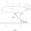
FIG. 1 is a side view of an autonomous underwater vehicle according to one embodiment. -
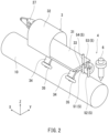
FIG. 2 is a perspective view showing a cart and inspection equipment. -
FIG. 3 is a side view showing the cart and the inspection equipment. -
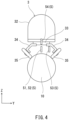
FIG. 4 is a rear view showing the cart and the inspection equipment. -
FIGS. 5A and 5B are conceptual diagrams showing an electric field when a sacrificial electrode has a tubular shape surrounding a seabed pipeline.FIG. 5A is a diagram when viewed from a lateral side of the pipeline.FIG. 5B is a sectional view taken along line VB-VB ofFIG. 5A . -
FIG. 6 is a conceptual diagram showing the electric field when the sacrificial electrode is located at a position away from the seabed pipeline. -
FIG. 1 shows an autonomous underwater vehicle (AUV) 1 according to one embodiment. The AUV 1 moves along anunderwater structure 10. In the present embodiment, theunderwater structure 10 is a seabed pipeline. However, theunderwater structure 10 does not necessarily have to be the seabed pipeline and may be, for example, a bridge pier. - Specifically, the AUV 1 includes: a
main body 21 having a streamline shape; and apropulsor 22 located at themain body 21. In the present embodiment, as rudder equipment that changes a course and a height, a movable vertical tail and a movable horizontal tail are located at a rear portion of themain body 21. However, the rudder equipment is not limited to this. When the course and the height can be changed only by thepropulsor 22, the rudder equipment is omitted, and a fixed wing for stabilizing the posture of themain body 21 may be included. - The
propulsor 22 can apply thrust to themain body 21 in a front-rear direction, left-right direction, and upper-lower direction of themain body 21. In addition, thepropulsor 22 can apply turning force to themain body 21 in a yaw direction around an upper-lower axis of themain body 21 and a pitch direction around a left-right axis of themain body 21. For example, thepropulsor 22 may include thrusters that are directed in different directions from each other or may include a single thruster of a swing type. - A
position detector 9 is located at a front portion of themain body 21.Control circuitry 7 and an inertial navigation system 8 (INS) are located inside themain body 21. - The
position detector 9 detects a position of theposition detector 9 relative to theunderwater structure 10. In the present embodiment, theposition detector 9 is a sonar that emits an acoustic beam to obtain positional information of theunderwater structure 10. However, theposition detector 9 may be a laser range finder that emits a light beam. - The
control circuitry 7 controls thepropulsor 22 based on the detection result of theposition detector 9 such that themain body 21 moves along theunderwater structure 10. To be specific, themain body 21 moves so as to trace the seabed pipeline as theunderwater structure 10 while maintaining a constant distance to theunderwater structure 10. - Regarding the
control circuitry 7, the functionality of the elements disclosed herein may be implemented using circuitry or processing circuitry which includes general purpose processors, special purpose processors, integrated circuits, ASICs ("Application Specific Integrated Circuits"), conventional circuitry and/or combinations thereof which are configured or programmed to perform the disclosed functionality. Processors are considered processing circuitry or circuitry as they include transistors and other circuitry therein. In the disclosure, the circuitry, units, or means are hardware that carry out or are programmed to perform the recited functionality. The hardware may be any hardware disclosed herein or otherwise known which is programmed or configured to carry out the recited functionality. When the hardware is a processor which may be considered a type of circuitry, the circuitry, means, or units are a combination of hardware and software, the software being used to configure the hardware and/or processor. - The inertial navigation system 8 includes: accelerometers that detect respective accelerations in directions in which three axes orthogonal to each other extend; and gyro sensors that detect respective angular velocities around the three axes. The inertial navigation system 8 calculates a movement direction of the
main body 21 from a reference position of themain body 21 and a movement distance of themain body 21 from the reference position of themain body 21, and calculates a current posture of themain body 21. - Based on the movement direction and movement distance of the
main body 21 from the reference position of themain body 21 which have been calculated by the inertial navigation system 8, thecontrol circuitry 7 calculates and grasps a position (longitude, latitude, and depth) of themain body 21 in a geographic coordinate system. - An
arm 23 is attached to a lower surface of themain body 21 through adriver 24. Thedriver 24 includes: afirst driving portion 25 that turns thearm 23 around the upper-lower axis of themain body 21; and asecond driving portion 26 that swings thearm 23 around the left-right axis of themain body 21. Thefirst driving portion 25 and thesecond driving portion 26 are controlled by thecontrol circuitry 7 in accordance with the position of themain body 21 relative to theunderwater structure 10 and the current posture of themain body 21. - A
cart 3 is coupled to a tip of thearm 23 through acoupler 27. Thecoupler 27 couples thecart 3 to the tip of thearm 23 such that thearm 23 can swing around a left-right axis and upper-lower axis of thecart 3.Inspection equipment 4 is attached to thecart 3. - More specifically, as shown in
FIGS. 2 to 4 , thecart 3 includes: a plate-shapedbase 31 that is in parallel with theunderwater structure 10; and acover 32 covering a front portion of thebase 31. Two pairs ofwheels 35 that roll on theunderwater structure 10 are attached to the base 31 throughbrackets 34 and attachingseats 33. In the present embodiment, since theunderwater structure 10 is the seabed pipeline having a circular section, eachwheel 35 is inclined at 45° with respect to the upper-lower direction of thecart 3. - The
inspection equipment 4 includes: an underwaterpotential sensor 5 that three-dimensionally measures a potential gradient in water; a metal potential sensor 6 (not shown inFIG. 4 ) that inspects an electric field producing body that is a part (a metal exposed portion or a corroded portion) of theunderwater structure 10 or a sacrificial electrode 11 (seeFIG. 5A, 5B, or FIG. 6 ); and a support that supports the underwaterpotential sensor 5 and the metalpotential sensor 6. - As shown in
FIGS. 5A and 5B , thesacrificial electrode 11 may have a tubular shape surrounding the seabed pipeline that is theunderwater structure 10, or as shown inFIG. 6 , thesacrificial electrode 11 may be located at a position away from the seabed pipeline. Thesacrificial electrode 11 produces an electric field as shown inFIG. 5A, 5B, or 6 . When a coating film of the seabed pipeline is peeled off, or the seabed pipeline is corroded, the metal exposed portion or the corroded portion produces the electric field as shown inFIGS. 5A and 5B . - The underwater
potential sensor 5 includes: afirst reference electrode 51, asecond reference electrode 52, and athird reference electrode 53 which are located on an opposing plane opposed to theunderwater structure 10; and afourth reference electrode 54 located above this opposing plane. Thesecond reference electrode 52 is located at a position away from thefirst reference electrode 51 in a first direction X on the opposing plane. Thethird reference electrode 53 is located at a position away from thefirst reference electrode 51 in a second direction Y orthogonal to the first direction X on the opposing plane. Thefourth reference electrode 54 is located at a position away from thefirst reference electrode 51 in a third direction orthogonal to the first direction X and the second direction Y. The first tofourth reference electrodes 51 to 54 are electrochemical electrodes. Examples of the electrochemical electrodes include silver/silver chloride electrodes and saturated calomel electrodes. - In the present embodiment, since the
underwater structure 10 is the seabed pipeline, the first direction X is an axial direction of the seabed pipeline, and the second direction Y is a horizontal direction orthogonal to the axial direction of the seabed pipeline. Moreover, at a portion where the seabed pipeline is parallel to a horizontal plane, the third direction Z is a vertical direction. - The inspection of the electric field producing body which is performed by the metal
potential sensor 6 is the measurement of the potential of metal that is the electric field producing body. The metalpotential sensor 6 includes: a metal chip that is metal-conductive with an inspection target; and a reference electrode. The accuracy of the inspection increases as a distance between the metal chip and a liquid junction portion of the reference electrode decreases. - Next, control performed by the
control circuitry 7 will be more specifically described. First, thecontrol circuitry 7 specifies the position of the electric field producing body by mapping the underwater electric field from the potential gradient measured by the underwaterpotential sensor 5 in accordance with the movement of the AUV 1. Next, thecontrol circuitry 7 controls thepropulsor 22 such that the AUV 1 moves to and stops at an inspection position that is a position at which the metalpotential sensor 6 is opposed to the electric field producing body. In this state, thecontrol circuitry 7 makes the metalpotential sensor 6 inspect the electric field producing body. - As described above, according to the AUV 1 of the present embodiment, since the underwater
potential sensor 5 three-dimensionally measures the potential gradient in water, the position of the electric field producing body can be specified. Moreover, when the position of the electric field producing body is specified, autonomous movement to the inspection position and autonomous inspection are performed by the control of thecontrol circuitry 7. Therefore, the electric field producing body can be inspected by using the AUV 1. - The present disclosure is not limited to the above embodiment, and various modifications may be made within the scope of the present disclosure.
- For example, the
control circuitry 7 may control thepropulsor 22 such that when the distance from the AUV 1 to the electric field producing body is a predetermined value or less, the speed of the AUV 1 decreases. According to this configuration, the potential gradient in water can be measured at short distance intervals by the decrease in the speed of the AUV 1. Therefore, the position of the electric field producing body can be accurately specified. - As a first aspect, the present disclosure provides an autonomous underwater vehicle including: a position detector that detects a position of the position detector relative to an underwater structure; a propulsor; control circuitry configured to control the propulsor based on a detection result of the position detector such that the autonomous underwater vehicle moves along the underwater structure and grasp a position of the autonomous underwater vehicle; an underwater potential sensor that three-dimensionally measures a potential gradient in water; and a metal potential sensor that inspects an electric field producing body that is a part of the underwater structure or a sacrificial anode, wherein: the control circuitry specifies a position of the electric field producing body by mapping an underwater electric field from the potential gradient measured by the underwater potential sensor in accordance with movement of the autonomous underwater vehicle; the control circuitry controls the propulsor such that the autonomous underwater vehicle moves to and stops at an inspection position that is a position at which the metal potential sensor is opposed to the electric field producing body; and in this state, the control circuitry makes the metal potential sensor inspect the electric field producing body.
- According to the above configuration, since the underwater potential sensor three-dimensionally measures the potential gradient in water, the position of the electric field producing body can be specified. Moreover, when the position of the electric field producing body is specified, the autonomous movement to the inspection position and the autonomous inspection are performed by the control of the control circuitry. Therefore, the electric field producing body can be inspected by using the autonomous underwater vehicle.
- As a second aspect, in addition to the first aspect, for example, the underwater potential sensor may include: a first reference electrode; a second reference electrode located at a position away from the first reference electrode in a first direction on an opposing plane opposed to the underwater structure; a third reference electrode located at a position away from the first reference electrode in a second direction orthogonal to the first direction on the opposing plane; and a fourth reference electrode located at a position away from the first reference electrode in a third direction orthogonal to the first direction and the second direction.
- As a third aspect, in addition to the second aspect, for example, the underwater structure may include a seabed pipeline, and the first direction may be an axial direction of the seabed pipeline.
- As a fourth aspect, in addition to any one of the first to third aspects, the control circuitry may control the propulsor such that when a distance from the autonomous underwater vehicle to the electric field producing body is a predetermined value or less, a speed of the autonomous underwater vehicle decreases. According to this configuration, the potential gradient in water can be measured at short distance intervals by the decrease in the speed of the autonomous underwater vehicle. Therefore, the position of the electric field producing body can be accurately specified.
Claims (4)
- An autonomous underwater vehicle comprising:a position detector that detects a position of the position detector relative to an underwater structure;a propulsor;control circuitry configured tocontrol the propulsor based on a detection result of the position detector such that the autonomous underwater vehicle moves along the underwater structure andgrasp a position of the autonomous underwater vehicle;an underwater potential sensor that three-dimensionally measures a potential gradient in water; anda metal potential sensor that inspects an electric field producing body that is a part of the underwater structure or a sacrificial anode, wherein:the control circuitry specifies a position of the electric field producing body by mapping an underwater electric field from the potential gradient measured by the underwater potential sensor in accordance with movement of the autonomous underwater vehicle;the control circuitry controls the propulsor such that the autonomous underwater vehicle moves to and stops at an inspection position that is a position at which the metal potential sensor is opposed to the electric field producing body; andin this state, the control circuitry makes the metal potential sensor inspect the electric field producing body.
- The autonomous underwater vehicle according to claim 1, wherein the underwater potential sensor includes:a first reference electrode;a second reference electrode located at a position away from the first reference electrode in a first direction on an opposing plane opposed to the underwater structure;a third reference electrode located at a position away from the first reference electrode in a second direction orthogonal to the first direction on the opposing plane; anda fourth reference electrode located at a position away from the first reference electrode in a third direction orthogonal to the first direction and the second direction.
- The autonomous underwater vehicle according to claim 2, wherein:the underwater structure includes a seabed pipeline; andthe first direction is an axial direction of the seabed pipeline.
- The autonomous underwater vehicle according to any one of claims 1 to 3, wherein the control circuitry controls the propulsor such that when a distance from the autonomous underwater vehicle to the electric field producing body is a predetermined value or less, a speed of the autonomous underwater vehicle decreases.
Applications Claiming Priority (2)
| Application Number | Priority Date | Filing Date | Title |
|---|---|---|---|
| JP2022093462 | 2022-06-09 | ||
| PCT/JP2023/020047 WO2023238733A1 (en) | 2022-06-09 | 2023-05-30 | Autonomous unmanned underwater vehicle |
Publications (2)
| Publication Number | Publication Date |
|---|---|
| EP4538165A1 true EP4538165A1 (en) | 2025-04-16 |
| EP4538165A4 EP4538165A4 (en) | 2026-05-27 |
Family
ID=89118208
Family Applications (1)
| Application Number | Title | Priority Date | Filing Date |
|---|---|---|---|
| EP23819713.1A Pending EP4538165A4 (en) | 2022-06-09 | 2023-05-30 | Autonomous unmanned underwater vehicle |
Country Status (4)
| Country | Link |
|---|---|
| US (1) | US20250354957A1 (en) |
| EP (1) | EP4538165A4 (en) |
| JP (1) | JP7734839B2 (en) |
| WO (1) | WO2023238733A1 (en) |
Family Cites Families (13)
| Publication number | Priority date | Publication date | Assignee | Title |
|---|---|---|---|---|
| JPH01145898U (en) * | 1988-03-31 | 1989-10-06 | ||
| JPH1172458A (en) | 1997-07-04 | 1999-03-16 | Nippon Boshoku Kogyo Kk | Underwater surface potential gradient detection method for steel |
| GB0100106D0 (en) * | 2001-01-03 | 2001-02-14 | Flight Refueling Ltd | Subsea navigation and survey |
| JP5806568B2 (en) * | 2011-09-26 | 2015-11-10 | 川崎重工業株式会社 | Underwater mobile inspection equipment and underwater inspection equipment |
| WO2016178045A1 (en) | 2015-05-05 | 2016-11-10 | Total Sa | Underwater vehicle for inspection of a subsea structure in a body of water and related method |
| DK3163288T3 (en) * | 2015-10-29 | 2018-11-12 | Cescor Srl | New probes and devices for the inspection of cathodic protection of subsea pipelines |
| JP6950961B2 (en) * | 2017-06-09 | 2021-10-13 | 日本防蝕工業株式会社 | Potential measurement jig for underwater structures, potential measurement method using this, and verification method of generated current |
| WO2018237057A1 (en) * | 2017-06-20 | 2018-12-27 | Delta Subsea Llc | APPARATUSES, SYSTEMS AND METHODS FOR EVALUATING CORROSION PREVENTION |
| CN108482618A (en) * | 2018-02-06 | 2018-09-04 | 青岛远创机器人自动化有限公司 | A kind of jacket Corrosion monitoring climbing robot of no magnetic interference |
| JP7137342B2 (en) * | 2018-04-10 | 2022-09-14 | 川崎重工業株式会社 | autonomous underwater vehicle |
| JP7147591B2 (en) * | 2019-01-25 | 2022-10-05 | 株式会社島津製作所 | Submarine structure detection device, submarine structure detection system, and submarine structure detection method |
| JP7255804B2 (en) * | 2019-09-04 | 2023-04-11 | 日本防蝕工業株式会社 | State quantity estimation method, state quantity estimation device, and program |
| CN113529092B (en) * | 2021-07-23 | 2023-06-20 | 中海石油(中国)有限公司 | An autonomous inspection method and system for cathodic protection potential detection of submarine pipelines |
-
2023
- 2023-05-30 US US18/872,633 patent/US20250354957A1/en active Pending
- 2023-05-30 WO PCT/JP2023/020047 patent/WO2023238733A1/en not_active Ceased
- 2023-05-30 JP JP2024526388A patent/JP7734839B2/en active Active
- 2023-05-30 EP EP23819713.1A patent/EP4538165A4/en active Pending
Also Published As
| Publication number | Publication date |
|---|---|
| EP4538165A4 (en) | 2026-05-27 |
| JPWO2023238733A1 (en) | 2023-12-14 |
| WO2023238733A1 (en) | 2023-12-14 |
| JP7734839B2 (en) | 2025-09-05 |
| US20250354957A1 (en) | 2025-11-20 |
Similar Documents
| Publication | Publication Date | Title |
|---|---|---|
| US11048274B2 (en) | Route setting method for underwater vehicle, underwater vehicle optimum control method using same, and underwater vehicle | |
| JP7175252B2 (en) | Ship docking support device | |
| EP3040680B1 (en) | Magnetic anomaly tracking for an inertial navigation system | |
| Arnold et al. | Robust model-aided inertial localization for autonomous underwater vehicles | |
| JP3949932B2 (en) | Autonomous underwater vehicle navigation control system | |
| CN101389976A (en) | Systems and methods for determining the position of an underwater vehicle | |
| CN109085597B (en) | Unmanned ship for underwater topography measurement | |
| RU2610149C1 (en) | Towed underwater vehicle, equipped with sonar equipment for detecting silting facilities and pipelines, and their subsequent monitoring | |
| Stateczny et al. | Hydrodron—New step for professional hydrography for restricted waters | |
| Noguchi et al. | Tracking omnidirectional surfaces using a low-cost autonomous underwater vehicle | |
| JP2023041501A (en) | Shore-arrival assisting device, shore-arrival assisting method, and shore-arrival assisting program | |
| JP7668510B2 (en) | Self-position estimation error correction method and system for underwater vehicle | |
| US20250354957A1 (en) | Autonomous underwater vehicle | |
| JP6723111B2 (en) | Gravity measuring device | |
| Gavrilina et al. | Attitude Control System of a Highly Maneuverable Hybrid ROV for Ship-Hull Inspection | |
| Choi et al. | Autonomous towed vehicle for underwater inspection in a port area | |
| Kita et al. | Prototyping of automatic navigation of underwater robot for underwater visual inspection | |
| JP2018163587A (en) | Moving object movement prediction method and movement prediction system | |
| JP2024022918A (en) | Flying vehicle and method of controlling the flying vehicle | |
| Antonelli et al. | Real-time path planning and obstacle avoidance for an autonomous underwater vehicle | |
| AU2012200886A1 (en) | System and method for determining the position of an underwater vehicle | |
| Augenstein et al. | Estimating inertial position and current in the midwater | |
| Troni et al. | Preliminary experimental evaluation of in-situ calibration methods for MEMS-based attitude sensors and Doppler sonars in underwater vehicle navigation | |
| US20260049821A1 (en) | Position fixing systems and methods | |
| EP4640551A1 (en) | Submersible |
Legal Events
| Date | Code | Title | Description |
|---|---|---|---|
| STAA | Information on the status of an ep patent application or granted ep patent |
Free format text: STATUS: THE INTERNATIONAL PUBLICATION HAS BEEN MADE |
|
| PUAI | Public reference made under article 153(3) epc to a published international application that has entered the european phase |
Free format text: ORIGINAL CODE: 0009012 |
|
| STAA | Information on the status of an ep patent application or granted ep patent |
Free format text: STATUS: REQUEST FOR EXAMINATION WAS MADE |
|
| 17P | Request for examination filed |
Effective date: 20241007 |
|
| AK | Designated contracting states |
Kind code of ref document: A1 Designated state(s): AL AT BE BG CH CY CZ DE DK EE ES FI FR GB GR HR HU IE IS IT LI LT LU LV MC ME MK MT NL NO PL PT RO RS SE SI SK SM TR |
|
| DAV | Request for validation of the european patent (deleted) | ||
| DAX | Request for extension of the european patent (deleted) | ||
| A4 | Supplementary search report drawn up and despatched |
Effective date: 20260429 |
|
| RIC1 | Information provided on ipc code assigned before grant |
Ipc: B63C 11/00 20060101AFI20260422BHEP Ipc: B63C 11/52 20060101ALI20260422BHEP Ipc: G01N 27/26 20060101ALI20260422BHEP Ipc: C23F 13/22 20060101ALI20260422BHEP |