EP4538146A2 - Saw cart - Google Patents
Saw cart Download PDFInfo
- Publication number
- EP4538146A2 EP4538146A2 EP24223075.3A EP24223075A EP4538146A2 EP 4538146 A2 EP4538146 A2 EP 4538146A2 EP 24223075 A EP24223075 A EP 24223075A EP 4538146 A2 EP4538146 A2 EP 4538146A2
- Authority
- EP
- European Patent Office
- Prior art keywords
- cart
- saw
- coupled
- frame
- throttle
- Prior art date
- Legal status (The legal status is an assumption and is not a legal conclusion. Google has not performed a legal analysis and makes no representation as to the accuracy of the status listed.)
- Pending
Links
Images








Classifications
-
- B—PERFORMING OPERATIONS; TRANSPORTING
- B28—WORKING CEMENT, CLAY, OR STONE
- B28D—WORKING STONE OR STONE-LIKE MATERIALS
- B28D7/00—Accessories specially adapted for use with machines or devices of the preceding groups
-
- B—PERFORMING OPERATIONS; TRANSPORTING
- B28—WORKING CEMENT, CLAY, OR STONE
- B28D—WORKING STONE OR STONE-LIKE MATERIALS
- B28D1/00—Working stone or stone-like materials, e.g. brick, concrete or glass, not provided for elsewhere; Machines, devices, tools therefor
- B28D1/02—Working stone or stone-like materials, e.g. brick, concrete or glass, not provided for elsewhere; Machines, devices, tools therefor by sawing
- B28D1/04—Working stone or stone-like materials, e.g. brick, concrete or glass, not provided for elsewhere; Machines, devices, tools therefor by sawing with circular or cylindrical saw-blades or saw-discs
- B28D1/045—Sawing grooves in walls; sawing stones from rocks; sawing machines movable on the stones to be cut
-
- B—PERFORMING OPERATIONS; TRANSPORTING
- B62—LAND VEHICLES FOR TRAVELLING OTHERWISE THAN ON RAILS
- B62B—HAND-PROPELLED VEHICLES, e.g. HAND CARTS OR PERAMBULATORS; SLEDGES
- B62B3/00—Hand carts having more than one axis carrying transport wheels; Steering devices therefor; Equipment therefor
- B62B3/02—Hand carts having more than one axis carrying transport wheels; Steering devices therefor; Equipment therefor involving parts being adjustable, collapsible, attachable, detachable or convertible
-
- B—PERFORMING OPERATIONS; TRANSPORTING
- B62—LAND VEHICLES FOR TRAVELLING OTHERWISE THAN ON RAILS
- B62B—HAND-PROPELLED VEHICLES, e.g. HAND CARTS OR PERAMBULATORS; SLEDGES
- B62B3/00—Hand carts having more than one axis carrying transport wheels; Steering devices therefor; Equipment therefor
- B62B3/10—Hand carts having more than one axis carrying transport wheels; Steering devices therefor; Equipment therefor characterised by supports specially adapted to objects of definite shape
-
- B—PERFORMING OPERATIONS; TRANSPORTING
- B62—LAND VEHICLES FOR TRAVELLING OTHERWISE THAN ON RAILS
- B62B—HAND-PROPELLED VEHICLES, e.g. HAND CARTS OR PERAMBULATORS; SLEDGES
- B62B3/00—Hand carts having more than one axis carrying transport wheels; Steering devices therefor; Equipment therefor
- B62B3/12—Hand carts having more than one axis carrying transport wheels; Steering devices therefor; Equipment therefor characterised by three-wheeled construction
-
- B—PERFORMING OPERATIONS; TRANSPORTING
- B62—LAND VEHICLES FOR TRAVELLING OTHERWISE THAN ON RAILS
- B62B—HAND-PROPELLED VEHICLES, e.g. HAND CARTS OR PERAMBULATORS; SLEDGES
- B62B2202/00—Indexing codes relating to type or characteristics of transported articles
- B62B2202/48—Tools
-
- B—PERFORMING OPERATIONS; TRANSPORTING
- B62—LAND VEHICLES FOR TRAVELLING OTHERWISE THAN ON RAILS
- B62B—HAND-PROPELLED VEHICLES, e.g. HAND CARTS OR PERAMBULATORS; SLEDGES
- B62B5/00—Accessories or details specially adapted for hand carts
- B62B5/06—Hand moving equipment, e.g. handle bars
- B62B5/064—Hand moving equipment, e.g. handle bars adaptable for different users, e.g. by means of pivoting elements
Definitions
- the present invention relates to a cart, and more particularly to a cart for a cut-off saw.
- Cut-off saws can be held directly by a user or supported by a cart.
- the cart allows the saw to make precise cuts into a floor surface such as concrete or asphalt. In order to do so, the cart needs to be able to support the saw and its associated equipment, adjust aspects of the saw, such as cutting depth, and control activation of the saw.
- the invention provides, in one aspect, a cart for carrying a cut-off saw having a saw blade.
- the cart includes a frame with an upper portion and a lower portion, a wheel arm pivotably coupled to the lower portion of the frame about a first axis, and a rear wheel assembly coaxial with the first axis and coupled to the frame and the wheel arm.
- the cart further includes a front wheel coupled to an end of the wheel arm opposite the rear wheel assembly, an adjustment lever pivotably coupled to the upper portion of the frame about a second axis, and a link having a first end pivotably coupled to the adjustment lever at a location spaced from the second axis, and a second end pivotably coupled to the wheel arm at a location between the first axis and the front wheel. Pivoting the adjustment lever about the second axis pivots the wheel arm about the first axis to adjust a vertical position of the front wheel relative to the upper portion of the frame, and therefore a vertical position of the saw blade relative to a support surface of the cart.
- the invention provides, in another aspect, a cart for carrying a cut-off saw having a saw blade, a motor drivably coupled to the saw blade, and a trigger for varying the rotational speed of the motor and saw blade.
- the cart includes a frame, a handle coupled to the frame, a throttle lever pivotably coupled to the handle, and a throttle cable having a first end and a second end opposite the first end. The first end is proximate the trigger to selectively pull the trigger, thereby varying the rotational speed of the motor and saw blade.
- the cart further includes an actuator supported by the handle and movable between a first position, in which pivoting movement of the throttle lever is incapable of tensioning the throttle cable for pulling the trigger, and a second position, in which pivoting movement of the throttle lever tensions the throttle cable for pulling the trigger.
- the invention provides, in another aspect, a cart for carrying a cut-off saw having a saw blade, a motor drivably coupled to the saw blade, and a first removable battery pack for powering the motor.
- the cart includes a frame with an upper portion and a lower portion, a wheel arm pivotably coupled to the lower portion of the frame, a rear wheel assembly coupled to the frame and/or the wheel arm, a front wheel coupled to an end of the wheel arm opposite the rear wheel assembly, a first mount coupled to the frame to which the cut-off saw is attachable, and a second mount coupled to the frame to which a second removable battery pack, which is interchangeable with the first removable battery pack, is attachable for storage.
- the cart may further include a water tank carried onboard the frame.
- the cart may include a bracket to removably support the water tank on the frame.
- the saw 15 includes a rear handle 105 that extends from the rear of the housing 75 in a direction generally opposite the support arm 80.
- a trigger 110 for operating the saw 15 and a lockout shuttle 115 that prevents the user from pulling the trigger 110 unless it is first depressed are both located on the rear handle 105.
- the saw 15 also includes a front handle 120 that wraps around an upper portion of the housing 75 and that in conjunction with the rear handle 105, provides grip areas to facilitate two-handed operation of the saw 15.
- the saw 15 includes an on-board battery pack 135 that provides power to an electric motor (not shown).
- the battery pack 135 is removably coupled to a battery receptacle 140, which is located on the upper portion of the housing 75.
- the front handle 120 at least partially surrounds the battery receptacle 140 and the battery pack 135, when the battery pack 135 is attached to the receptacle 140.
- the battery pack 135 is a power tool battery pack and includes a battery housing 145 and a plurality of rechargeable battery cells (not shown) disposed within the battery housing 145.
- the battery cells are lithium-based battery cells but can alternatively have any other suitable chemistry.
- the battery pack 135 has a nominal output voltage of about 80V.
- the battery pack 135 can have a different nominal voltage, such as, for example, 36V, 40V, 72V, between 36V and about 80V, or greater than 40V.
- the battery receptacle 140 may be incorporated on the cart 10, instead of the saw 15, to provide electrical power to the motor of the saw 15.
- the saw 15 further includes a fluid distribution system 150.
- the fluid distribution system 150 includes a connector 155 attachable to a fluid supply line 170 ( FIG. 11 ), a control valve 160 supported upon the front handle 120, and a distributor 165 supported upon the guard 90.
- the supply line 170 provides fluid, such as water, to the fluid distribution system 150 from an external source.
- the external source is a water tank 175 ( FIG. 1 ) carried onboard the cart 10.
- the water tank 175 includes a connector 180 ( FIG. 11 ), which may include an integrated shutoff valve, to which the supply line 170 is connected.
- a first line extends from the connector 155 to the control valve 160
- a second line extends from the control valve 160 to the distributor 165.
- the distributor 165 includes a pair of spray nozzles 185 disposed on opposite sides of the guard 90 connected by a supply line 190.
- the spray nozzles 185 are operable to discharge fluid onto each side of the cutting wheel 85 for cooling, lubrication, and dust abatement.
- the cart 10 includes a frame 25 to which the saw 15 is attachable, a handle 30 upwardly extending from the frame 25 that is graspable by a user for maneuvering the cart 10, a front wheel 35, and a rear wheel assembly 40 having two rear wheels 540, 545.
- the frame 25 includes a material discharge guard (e.g., mud flap 45 ( FIG. 3 )) that blocks material cut by the saw 15 from contacting a user of the cart 10 and a loop 48 ( FIG. 6 ) that is used as a lifting point or hoist loop.
- the loop 48 is coupled to an upper portion of the frame 25 and allows a device, such as a crane or the like, to hook onto the cart 10 for easy transportation of the cart 10.
- the loop 48 is capable of supporting up to quadruple the weight of the cart 10.
- the loop 48 may be a separate component from the frame 25 that is attached thereto (e.g., by welding, etc.).
- the loop 48 may be integrally formed with the frame 25.
- the cart 10 further includes first and second latches 50 ( FIG. 1 ), 55 ( FIG. 5 ) that are used to retain the water tank 175 on a bracket 58 ( FIG. 3 ) coupled to the frame 25.
- the first and second latches 50, 55 are on opposite sides of the water tank 175 when positioned for use.
- the first and second latches 50, 55 are over-center latches that apply a clamping force to hooks 60 on the water tank 175 to pull the water tank 175 downward and secure it in place.
- the bracket 58 is removably coupled to the frame 25 so the frame 25 can support alternative brackets 1100 that support alternative water tanks 1110 ( FIG. 23 ).
- the cart 10 includes a mounting assembly 200 to secure the saw 15 to the frame 25.
- the mounting assembly 200 includes a front mount 205 on a lower portion of the frame 25 and a rear mount 210 on an upper portion of the frame 25.
- the front mount 205 defines a channel 220 in which a lower portion of the front handle 120 of the saw 15 is receivable.
- the channel 220 is open along its top and lateral sides to facilitate insertion of the handle 120 from the top of the channel 220 (i.e., in a direction parallel the y-axis shown in FIG. 1 ) or from the side of the channel 220 (i.e., in a direction parallel to the z-axis).
- the rear mount 210 includes a housing 235 and a cover 240 that is pivotably coupled to the housing 235 about an axis (not shown).
- the housing 235 includes parallel bores 250a, 250b through which a threaded rod 225 and a guide rod 230, respectively, protrude for supporting the housing 235 on the frame 25.
- the guide rod 230 is cantilevered from the frame 25 and includes a smooth cylindrical outer periphery along which the bore 250a is slidable.
- the threaded rod 225 is also cantilevered from the frame 25, and includes external threads that are engaged with a bushing 251 that is welded in the frame 25. Further description of the operation of the threaded rod 225 appears below.
- the housing 235 and cover 240 define a cavity 255 ( FIG. 4 ) in which the rear handle 105 of the saw 15 is positioned.
- the cover 240 is pivoted away from the housing 235 toward an open position, the rear handle 105 is removable from the cavity 255.
- the cover 240 includes a boss 260 on its interior that presses the lockout shuttle 115 of the saw 15 when the cover 240 is moved to the closed position, which allows the trigger 110 to be pulled to operate the saw 15.
- the cover 240 and/or the housing 235 may include a resilient member (e.g., a compression or torsion spring) that biases the cover 240 away from the housing 235 to keep the cavity open for ease of tool attachment.
- the rear mount 210 further includes two latches 265 that secures the cover 240 in the closed position.
- the latches 265 are configured as an over-center latches 265 to apply a clamping force between the cover 240 and the housing 235 to thereby maintain the lockout shuttle 115 in an override position.
- a user holds the rear and front handles 105, 120 of the saw 15 and aligns the rear handle 105 with the rear mount 210 and the front handle 120 with the front mount 205.
- the user then lowers the front handle 120 along the y-axis into the channel 220.
- the rear handle 105 is moved transversely along the z-axis and positioned into the portion of the cavity 255 defined by the housing 235.
- the cover 240 is then pivoted to the closed position and the latches 265 adjusted to its locking configuration, thereby securing the saw 15 on the cart 10.
- the cover 240 includes internal features (e.g., integral guides, etc.) that bias the handle 105 of the saw 15 into supports 268 of the housing 235.
- the cover 240 includes internal features that naturally guide the handle 105 into the cavity 255 as the cover 240 is being closed to secure the handle 105 in the rear mount 210. The motion of pivoting the cover 240 to the closed position engages the lockout shuttle 115 with the boss 260, moving the lockout shuttle 115 to the override position where the trigger 110 may be pulled to activate the saw 15.
- the interlock system 420 includes a housing 440 coupled to the handle 30 and an actuator (e.g., a button 445) that is biased by a spring 450 to protrude from a top side of the housing 440.
- the interlock system 420 includes a first arcuate bracket 455 that is coupled for co-rotation with the throttle lever 410 and a second arcuate bracket 460 that is coupled to the first end 430 of the throttle cable 415.
- the first arcuate bracket 455 includes a slot 475 on its outer periphery in which a pin 465 is receivable.
- the second arcuate bracket 460 includes the pin 465 pivotably coupled thereto by extension arms 468.
- pivoting movement of the throttle lever 410 is incapable of tensioning the throttle cable 415 for pulling the trigger 110.
- the pin 465 is received within the slot 475 to thereby rotationally unitize the first and second arcuate brackets 455, 460 to pivot in unison with the throttle lever 410 when it is depressed.
- pivoting movement of the throttle lever 410 tensions the throttle cable 415 for pulling the trigger 110.
- the remote throttle system 405 also includes an actuator arm 480 pivotably coupled to the housing 235 of the rear mount 210.
- the second end 435 of the throttle cable 415 is coupled to the actuator arm 480.
- the actuator arm 480 is pivotable and includes a finger 490 positioned beneath the trigger 110 of the cut off saw 15, when positioned on the cut off saw cart 10.
- the remote throttle system 405 includes a first spring 494 seated on the throttle cable 415 between the actuator arm 480 and the housing 235 and a second spring 495 between the actuator arm 480 and the second end 435 of the throttle cable 415.
- the first and second springs 494, 495 allow the second end 435 of the throttle cable 415 to continue moving after the finger 490 has squeezed the trigger 110 to its maximum depressed position. This ensures that the throttle lever 410, when pivoted to its maximum depressed position against the handle 30, pulls the trigger 110 to its maximum depressed position coinciding with the maximum rotational speed of the cutting wheel 85 (in an embodiment of the saw 15 where the trigger 110 is configured as a variable-speed trigger).
- the throttle cable 415 is routed through the handle 30 and/or the frame 25 of the cart 10. In such embodiments, the throttle cable 415 exits the housing 440 into the handle 30 of the cart 10, and is then routed from the handle 30 into a lower portion of the frame 25.
- the second end of the throttle cable 415 exits the frame 25 adjacent the housing 235 for connection to the actuator arm 480. All entry and exit openings in the frame 25 may include a grommet to prevent chaffing the jacket of the throttle cable 415. Routing the throttle cable 415 through the frame 25 and handle 30 conceals and protects it.
- a user depresses the button 445 to the second position, which depresses the pin 465 against the bias of the torsion spring 470 into the slot 475 to rotationally unitize the first and second arcuate brackets 455, 460.
- a user then pivots the throttle lever 410 towards the handle 30, pivoting the arcuate brackets 455, 460 and tensioning the throttle cable 415.
- the throttle cable 415 progressively pulls the actuator arm 480 towards the trigger 110 of the saw 15.
- the finger 490 squeezes the trigger 110 to activate the motor, thereby varying the rotational speed of the cutting wheel 85 on the saw 15.
- the torsion spring 470 removes the pin 465 from the slot 475, and the spring 450 displaces the button 445 away from the pin 465.
- a user In order to re-activate the cutting wheel 85, a user must again depress the button 445 before pulling the throttle lever 410 towards the handle 30.
- the cart 10 includes a track control system 505 that adjusts the skew angle of the cutting wheel 85 relative to the support surface 20.
- the track control system 505 includes the threaded rod 225 and the guide rod 230, discussed above. As discussed above, the threaded rod 225 is received within the bore 250a and the threaded bushing 251 welded in the frame 25, whereas the guide rod 230 is slidably received within the bore 250b.
- the threaded rod 225 includes a rotatable knob 510.
- the rear mount 210 When the knob 510 and the threaded rod 225 are rotated in a counter-clockwise direction, the rear mount 210 (and thus the rear handle 105 of the saw 15) are moved towards the frame 25, which in turn moves the cutting wheel 85 away from the wheel arm 275.
- the rear mount 210 when the knob 510 and the threaded rod 225 are rotated in a clockwise direction, the rear mount 210 (and thus the rear handle 105 of the saw 15) are moved away from the frame 25, which in turn moves the cutting wheel 85 towards the wheel arm 275. In this manner, the skew angle of the cutting wheel 85 relative to the x-axis ( FIG. 1 ) can be adjusted.
- the cart 10 further includes a battery pack mount 515 coupled to the frame 25 to which a spare removable battery pack 525, which is interchangeable with the removable battery pack 135 on the saw 15, is attachable for storage.
- the battery pack mount includes a C-shaped bracket 520 coupled to the frame 25 and defines a channel 530.
- the removable battery pack 525 includes a rail 535 that has an increased thickness portion 538.
- the rail 535 is positioned in the channel 530 of the C-shaped bracket 520 to mount the removable battery pack 525 to the cart 10.
- the rail 535 is friction fit inside the channel 530 of the C-shaped bracket 520 at a point where the rail 535 progresses to the increased thickness portion 538.
- the battery rail 535 may extend the full length of the removable battery pack 525 or only a portion of the removable battery pack 525.
- the battery pack mount 515 further includes a platform 539 that supports the bottom of the battery pack 525.
- the battery pack mount 515 may be coupled to other locations on the frame 25 other than where it is illustrated.
- the battery pack mount 515 includes a latch for securing the removable battery pack 525.
- the battery pack mount 515 includes terminals for on board charging of the removable battery pack 525.
- the battery pack mount 515 stores multiple battery packs.
- the cart includes an adjustable handle assembly 565.
- the handle assembly 565 includes the handle 30 that is graspable by a user pushing the cart 10 and a joint 575 for securing the handle 30 in a desired rotational position relative to the frame 25.
- the joint 575 includes a first clamshell 580 with teeth 585 fixed to the handle 30, and a second half clamshell 590 with teeth 585 fixed to the frame 25. When the teeth 585 of the first and second clamshells 580, 590 are meshed, the handle 30 is rotationally locked.
- the handle assembly 565 also includes a bolt shank 595 extending through the handle 30 and the first clamshell 580, a knob 600 on one end of the shank 595, and an opposite threaded end 605 threaded to a threaded bore 610 in the second half-clamshell 590.
- a compression spring may be positioned between the clamshells 580, 590 to push them apart.
- the joint 575 is positioned on a side of the adjustment lever 280 that is further away from the frame 25. In other embodiments, the joint 575 may be positioned on a side of the adjustment lever 280 that is closer to the frame 25 as shown FIG. 15 .
- a user can rotate the knob 600 to loosen the bolt shank 595 from the threaded bore 610 of the second half-clamshell 590 drawing the first half-clamshell 580 away from the second half-clamshell 590.
- the handle 30 can be rotated relative to the first half-clamshell 580 and bolt shank 595 to a desired height.
- a user can rotate the knob 600 in the opposite direction to tighten the connection between the shank 595 and the threaded bore 610, which re-engages the teeth 585 of the respective clamshells 580, 590, again locking the rotational position (and therefore the height) of the handle 30 relative to the frame 25.
- the cart 10 includes a tracking device 614.
- the tracking device 614 shares location information, last used date and time, and other metrics with a user.
- the tracking device 614 may communicate with a user via a Bluetooth enabled device such as a smart phone with an application for the tracking device 614.
- the tracking device 614 may be coupled to the frame 25 of the cart 10, the saw 15, or other components of the cart 10.
- the tracking device 614 may be coupled to the cart 10 using an adhesive, fasteners, tie wraps, or the like.
- the tracking device 614 is mounted on the frame 25 of the cart 10 adjacent the battery pack mount 515.
- the cart 10 includes other storage spaces to mount the tracking device to the cart 10 where the tracking device will not interfere with any moving components on the cart 10 or otherwise be subject to impacts or undesired contact during normal use of the cart 10.
- FIG. 14 illustrates a rear wheel assembly 640 for the cut off saw cart 10 according to another embodiment of the invention.
- the rear wheel assembly 640 includes a left wheel 642, a right wheel 645, a solid axle 650 connecting the left and right wheels 642, 645 and an adjustment knob 655.
- the axle 650 is supported by a tube 660 on the cart 10 that extends through the second end 295 of the wheel arm 275 and is coaxial with the axis A2.
- the axle 650 remains stationary within the tube 660 while the left and right wheels 640, 645 rotate around the axle 650.
- the adjustment knob 655 includes a threaded screw (not shown) that may be loosened in and out of contact with the axle 650.
- a user can rotate the adjustment knob 655 to loosen the threaded screw, allowing the axle 650 to slide linearly along the axis A2 within the tube 660.
- a user can rotate the adjustment knob 655 to tighten the threaded screw and secure the axle 650 in place. This permits either of the wheels 640, 645 to be moved further inboard if it is desired to push the cart 10 with the attached saw 15 in close proximity to a wall.
- FIG. 16 illustrates a depth adjustment assembly 710 on the cart 10 according to another embodiment of the invention.
- the depth adjustment assembly 710 includes a mounting plate 715 that supports the saw 15, a foot treadle 720, and a ratchet gear 725.
- the mounting plate 715 is coupled to the frame 25 of the cart 10 about a pivot shaft 730.
- the mounting plate 715, and thus the saw 15, is pivotable relative to the frame 25 about the pivot shaft 730.
- the ratchet gear 725 is coupled to the mounting plate 715 on one side of the frame 25 and to the foot treadle 720 on the other side of the frame 25. As shown in FIGS.
- FIG. 19 illustrates a depth adjustment assembly 810 according to another embodiment of the invention.
- the depth adjustment assembly 810 is similar to the depth adjustment assembly 710 but includes a hand crank 815 instead of a foot treadle 720.
- the hand crank 815 is coupled to the mounting plate 715 through a gear assembly 825.
- the gear assembly 825 is driven which pivots the mounting plate 715 about the pivot shaft 730 adjusting the cutting depth of the saw 15.
- an actuator 830 e.g., a jack, pump, or the like
- a user may then control the actuator 830 to pivot the mounting plate 715 about the pivot shaft 730.
- FIG. 21 illustrates a depth adjustment assembly 910 on the cart 10 according to another embodiment of the invention.
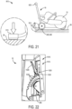
- the depth adjustment assembly 910 includes a foot pedal 915 that when engaged releases a lock on the axle of the wheels 540, 545 allowing a push handle 920 to be pivoted forward to plunge the saw 15 into the support surface 20. When the foot pedal 915 is fully engaged, it rests on the support surface 20.
- Pivoting the hand lever 1015 translates the link 285, which then raises/lowers the wheel arm 275. Raising the wheel arm 275 lowers the cut off saw 15, thus increasing the cutting depth of the cutting wheel 85, whereas lowering the wheel arm 275 raises the cut off saw 15, thus reducing the cutting depth of the cutting wheel 85.
Landscapes
- Engineering & Computer Science (AREA)
- Mechanical Engineering (AREA)
- Chemical & Material Sciences (AREA)
- Combustion & Propulsion (AREA)
- Transportation (AREA)
- Mining & Mineral Resources (AREA)
- Handcart (AREA)
Abstract
Description
- This application claims priority to co-pending
U.S. Provisional Patent Application No. 62/699,271 filed on July 17, 2018 - The present invention relates to a cart, and more particularly to a cart for a cut-off saw.
- Power tools such as, for instance, cut-off saws, generally have many applications. Cut-off saws can be held directly by a user or supported by a cart. The cart allows the saw to make precise cuts into a floor surface such as concrete or asphalt. In order to do so, the cart needs to be able to support the saw and its associated equipment, adjust aspects of the saw, such as cutting depth, and control activation of the saw.
- The invention provides, in one aspect, a cart for carrying a cut-off saw having a saw blade. The cart includes a frame with an upper portion and a lower portion, a wheel arm pivotably coupled to the lower portion of the frame about a first axis, and a rear wheel assembly coaxial with the first axis and coupled to the frame and the wheel arm. The cart further includes a front wheel coupled to an end of the wheel arm opposite the rear wheel assembly, an adjustment lever pivotably coupled to the upper portion of the frame about a second axis, and a link having a first end pivotably coupled to the adjustment lever at a location spaced from the second axis, and a second end pivotably coupled to the wheel arm at a location between the first axis and the front wheel. Pivoting the adjustment lever about the second axis pivots the wheel arm about the first axis to adjust a vertical position of the front wheel relative to the upper portion of the frame, and therefore a vertical position of the saw blade relative to a support surface of the cart.
- The invention provides, in another aspect, a cart for carrying a cut-off saw having a saw blade, a motor drivably coupled to the saw blade, and a trigger for varying the rotational speed of the motor and saw blade. The cart includes a frame, a handle coupled to the frame, a throttle lever pivotably coupled to the handle, and a throttle cable having a first end and a second end opposite the first end. The first end is proximate the trigger to selectively pull the trigger, thereby varying the rotational speed of the motor and saw blade. The cart further includes an actuator supported by the handle and movable between a first position, in which pivoting movement of the throttle lever is incapable of tensioning the throttle cable for pulling the trigger, and a second position, in which pivoting movement of the throttle lever tensions the throttle cable for pulling the trigger.
- The invention provides, in another aspect, a cart for carrying a cut-off saw having a saw blade, a motor drivably coupled to the saw blade, and a first removable battery pack for powering the motor. The cart includes a frame with an upper portion and a lower portion, a wheel arm pivotably coupled to the lower portion of the frame, a rear wheel assembly coupled to the frame and/or the wheel arm, a front wheel coupled to an end of the wheel arm opposite the rear wheel assembly, a first mount coupled to the frame to which the cut-off saw is attachable, and a second mount coupled to the frame to which a second removable battery pack, which is interchangeable with the first removable battery pack, is attachable for storage.
- In combination with any of the abovementioned embodiments, the cart may further include a water tank carried onboard the frame. In some embodiments, the cart may include a bracket to removably support the water tank on the frame.
- In combination with any of the abovementioned embodiments, the cart may further include a loop coupled to an upper portion of the frame to permit a device, such as a crane or the like, to hook onto the cart for easy transportation of the cart.
- In combination with any of the abovementioned embodiments, the cart may further include a rear wheel assembly having a left wheel, a right wheel, a solid axle connecting the left and right wheels, and an adjustment knob. To adjust the lateral position of the axle and wheels, a user can rotate the adjustment knob, allowing the axle to slide linearly relative to the frame. Once a desired position has been reached, a user can rotate the adjustment knob to secure the axle in place.
- In combination with any of the abovementioned embodiments, the cart may further include a depth adjustment assembly for changing a cutting depth of the cut-off saw. The depth adjustment assembly may include a hand crank or a foot treadle coupled to a mounting plate for the cut-off saw through a gear assembly. As a user rotates the hand crank or the foot treadle, the gear assembly is driven which pivots the mounting plate about a pivot shaft, thereby adjusting the cutting depth of the saw.
- In combination with any of the abovementioned embodiments, the cart may further include a depth adjustment assembly for changing a cutting depth of the cut-off saw. The depth adjustment assembly may include an actuator coupled to a mounting plate for the cut-off saw. In response to activation of the actuator, the mounting plate is pivoted about a pivot shaft, thereby adjusting the cutting depth of the saw.
- In combination with any of the abovementioned embodiments, the cart may further include a depth adjustment assembly for changing a cutting depth of the cut-off saw. The depth adjustment assembly may include a foot pedal that when engaged releases a lock on a rear axle of the cart allowing a push handle to be pivoted forward to plunge the saw into a support surface. When the foot pedal is fully engaged, it rests on the support surface.
- Other aspects of the invention will become apparent by consideration of the detailed description and accompanying drawings.
-
-
FIG. 1 is a front perspective view of a cart in accordance with an embodiment of the invention supporting a cut-off saw. -
FIG. 1A is a front perspective of the cart ofFIG. 1 without the cut-off saw. -
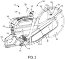
FIG. 2 is a perspective view of the cut-off saw ofFIG. 1 . -
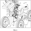
FIG. 3 is an enlarged view of a rear mount of the cart ofFIG. 1A for attaching the cut-off saw. -
FIG. 4 is a side view of the rear mount ofFIG. 3 in an open position. -
FIG. 5 is a side view of the cart ofFIG. 1A , illustrating a depth adjustment assembly. -
FIG. 6 is a cutaway perspective view of a portion of the depth adjustment assembly ofFIG. 1A . -
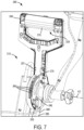
FIG. 7 is another cutaway perspective view of a portion of the depth assembly ofFIG. 1A . -
FIG. 8 is a cutaway perspective view of a remote throttle system of the cart ofFIG. 1A . -
FIG. 9 is a top view of a battery mount on the cart ofFIG. 1 with a battery pack attached. -
FIG. 10 is a perspective view of the battery mount ofFIG. 9 without the battery pack. -
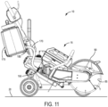
FIG. 11 is a side view of the cart ofFIG. 1 . -
FIG. 12 is an enlarged plan view of an adjustable handle assembly on the cart ofFIG. 1A . -
FIG. 13 is a cross-sectional view of the adjustable handle assembly ofFIG. 12 . -
FIG. 14 is a rear perspective view of a rear wheel assembly according to another embodiment of the invention on the cart ofFIG. 1A . -
FIG. 15 is an enlarged plan view of an adjustable handle assembly according to another embodiment of the invention on the cart ofFIG. 1A . -
FIG. 16 is a perspective view of a depth adjustment assembly according to another embodiment of the invention on the cart ofFIG. 1A . -
FIG. 17 is a side view of the depth adjustment assembly ofFIG. 16 in a first position. -
FIG. 18 is a side view of the depth adjustment assembly ofFIG. 16 in a second position. -
FIG. 19 is a perspective view of a depth adjustment assembly according to another embodiment of the invention on the cart ofFIG. 1A . -
FIG. 20 is a perspective view of a depth adjustment assembly according to another embodiment of the invention on the cart ofFIG. 1A . -
FIG. 21 is a perspective view of a depth adjustment assembly according to another embodiment of the invention on the cart ofFIG. 1A . -
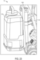
FIG. 22 is a perspective view of a depth adjustment assembly according to another embodiment of the invention on the cart ofFIG. 1A . -
FIG. 23 is a perspective view of a water tank according to another embodiment of the invention on the cart ofFIG. 1A . - Before any embodiments of the invention are explained in detail, it is to be understood that the invention is not limited in its application to the details of construction and the arrangement of components set forth in the following description or illustrated in the following drawings. The invention is capable of other embodiments and of being practiced or of being carried out in various ways.
-
FIG. 1 illustrates acart 10 for supporting a power tool, such as a cut-off saw 15. Thecart 10 is capable of conveying thesaw 15 over surfaces during operation and for transport. Thecart 10 is able to transport thesaw 15 in a transport direction, along the x-axis shown inFIG. 1 , in either a forward or backwards direction. - With reference to
FIG. 2 , thesaw 15 includes ahousing 75, asupport arm 80 coupled to and extending from thehousing 75, acutting wheel 85 carried by thesupport arm 80, and aguard 90 covering a portion of the circumference of thecutting wheel 85. Thecutting wheel 85 can be a blade, an abrasive disk, or any other rotatable element capable of removing material from a workpiece. In the illustrated embodiment, thecutting wheel 85 has a diameter greater than 9 inches and is preferably 14 inches in diameter. In other embodiments, thecutting wheel 85 can be between about 10 inches and about 16 inches in diameter. - The
saw 15 includes arear handle 105 that extends from the rear of thehousing 75 in a direction generally opposite thesupport arm 80. Atrigger 110 for operating thesaw 15 and alockout shuttle 115 that prevents the user from pulling thetrigger 110 unless it is first depressed are both located on therear handle 105. Thesaw 15 also includes afront handle 120 that wraps around an upper portion of thehousing 75 and that in conjunction with therear handle 105, provides grip areas to facilitate two-handed operation of thesaw 15. - The
saw 15 includes an on-board battery pack 135 that provides power to an electric motor (not shown). Thebattery pack 135 is removably coupled to abattery receptacle 140, which is located on the upper portion of thehousing 75. As such, thefront handle 120 at least partially surrounds thebattery receptacle 140 and thebattery pack 135, when thebattery pack 135 is attached to thereceptacle 140. Thebattery pack 135 is a power tool battery pack and includes abattery housing 145 and a plurality of rechargeable battery cells (not shown) disposed within thebattery housing 145. The battery cells are lithium-based battery cells but can alternatively have any other suitable chemistry. In the illustrated embodiment, thebattery pack 135 has a nominal output voltage of about 80V. In other embodiments, thebattery pack 135 can have a different nominal voltage, such as, for example, 36V, 40V, 72V, between 36V and about 80V, or greater than 40V. In an alternative embodiment, thebattery receptacle 140 may be incorporated on thecart 10, instead of thesaw 15, to provide electrical power to the motor of thesaw 15. - With continued reference to
FIG. 2 , thesaw 15 further includes afluid distribution system 150. Thefluid distribution system 150 includes aconnector 155 attachable to a fluid supply line 170 (FIG. 11 ), acontrol valve 160 supported upon thefront handle 120, and adistributor 165 supported upon theguard 90. Thesupply line 170 provides fluid, such as water, to thefluid distribution system 150 from an external source. In the illustrated embodiment, the external source is a water tank 175 (FIG. 1 ) carried onboard thecart 10. Thewater tank 175 includes a connector 180 (FIG. 11 ), which may include an integrated shutoff valve, to which thesupply line 170 is connected. A first line (not shown) extends from theconnector 155 to thecontrol valve 160, and a second line (not shown) extends from thecontrol valve 160 to thedistributor 165. In the illustrated embodiment, thedistributor 165 includes a pair ofspray nozzles 185 disposed on opposite sides of theguard 90 connected by asupply line 190. Thespray nozzles 185 are operable to discharge fluid onto each side of thecutting wheel 85 for cooling, lubrication, and dust abatement. - With reference to
FIGS. 1 and1A , thecart 10 includes aframe 25 to which thesaw 15 is attachable, ahandle 30 upwardly extending from theframe 25 that is graspable by a user for maneuvering thecart 10, afront wheel 35, and arear wheel assembly 40 having tworear wheels frame 25 includes a material discharge guard (e.g., mud flap 45 (FIG. 3 )) that blocks material cut by thesaw 15 from contacting a user of thecart 10 and a loop 48 (FIG. 6 ) that is used as a lifting point or hoist loop. Theloop 48 is coupled to an upper portion of theframe 25 and allows a device, such as a crane or the like, to hook onto thecart 10 for easy transportation of thecart 10. Theloop 48 is capable of supporting up to quadruple the weight of thecart 10. In some embodiments, theloop 48 may be a separate component from theframe 25 that is attached thereto (e.g., by welding, etc.). In other embodiments, theloop 48 may be integrally formed with theframe 25. Thecart 10 further includes first and second latches 50 (FIG. 1 ), 55 (FIG. 5 ) that are used to retain thewater tank 175 on a bracket 58 (FIG. 3 ) coupled to theframe 25. The first andsecond latches water tank 175 when positioned for use. The first andsecond latches hooks 60 on thewater tank 175 to pull thewater tank 175 downward and secure it in place. Thebracket 58 is removably coupled to theframe 25 so theframe 25 can supportalternative brackets 1100 that support alternative water tanks 1110 (FIG. 23 ). - With reference to
FIG. 1A , thecart 10 includes a mountingassembly 200 to secure thesaw 15 to theframe 25. The mountingassembly 200 includes afront mount 205 on a lower portion of theframe 25 and arear mount 210 on an upper portion of theframe 25. As shown inFIGS. 1A , thefront mount 205 defines achannel 220 in which a lower portion of thefront handle 120 of thesaw 15 is receivable. Thechannel 220 is open along its top and lateral sides to facilitate insertion of thehandle 120 from the top of the channel 220 (i.e., in a direction parallel the y-axis shown inFIG. 1 ) or from the side of the channel 220 (i.e., in a direction parallel to the z-axis). - With reference to
FIG. 3 , therear mount 210 includes ahousing 235 and acover 240 that is pivotably coupled to thehousing 235 about an axis (not shown). Thehousing 235 includesparallel bores rod 225 and aguide rod 230, respectively, protrude for supporting thehousing 235 on theframe 25. Theguide rod 230 is cantilevered from theframe 25 and includes a smooth cylindrical outer periphery along which thebore 250a is slidable. The threadedrod 225 is also cantilevered from theframe 25, and includes external threads that are engaged with abushing 251 that is welded in theframe 25. Further description of the operation of the threadedrod 225 appears below. When thecover 240 is closed, thehousing 235 and cover 240 define a cavity 255 (FIG. 4 ) in which therear handle 105 of thesaw 15 is positioned. When thecover 240 is pivoted away from thehousing 235 toward an open position, therear handle 105 is removable from thecavity 255. - With reference to
FIG. 4 , thecover 240 includes aboss 260 on its interior that presses thelockout shuttle 115 of thesaw 15 when thecover 240 is moved to the closed position, which allows thetrigger 110 to be pulled to operate thesaw 15. In some embodiments, thecover 240 and/or thehousing 235 may include a resilient member (e.g., a compression or torsion spring) that biases thecover 240 away from thehousing 235 to keep the cavity open for ease of tool attachment. Therear mount 210 further includes twolatches 265 that secures thecover 240 in the closed position. In the illustrated embodiment, thelatches 265 are configured as an over-center latches 265 to apply a clamping force between thecover 240 and thehousing 235 to thereby maintain thelockout shuttle 115 in an override position. - To position the
saw 15 on thecart 10, a user holds the rear and front handles 105, 120 of thesaw 15 and aligns therear handle 105 with therear mount 210 and thefront handle 120 with thefront mount 205. The user then lowers thefront handle 120 along the y-axis into thechannel 220. Simultaneously, with thecover 240 in its open position, therear handle 105 is moved transversely along the z-axis and positioned into the portion of thecavity 255 defined by thehousing 235. Thecover 240 is then pivoted to the closed position and thelatches 265 adjusted to its locking configuration, thereby securing thesaw 15 on thecart 10. In some embodiments, thecover 240 includes internal features (e.g., integral guides, etc.) that bias thehandle 105 of thesaw 15 intosupports 268 of thehousing 235. In other words, thecover 240 includes internal features that naturally guide thehandle 105 into thecavity 255 as thecover 240 is being closed to secure thehandle 105 in therear mount 210. The motion of pivoting thecover 240 to the closed position engages thelockout shuttle 115 with theboss 260, moving thelockout shuttle 115 to the override position where thetrigger 110 may be pulled to activate thesaw 15. - With reference to
FIGS. 5 , thecart 10 further includes adepth adjustment assembly 270 for varying the plunge depth of thecutting wheel 85 into asupport surface 20 of thecart 10. Thedepth adjustment assembly 270 includes awheel arm 275, anadjustment lever 280, and alink 285 interconnecting thewheel arm 275 and theadjustment lever 280. Thewheel arm 275 includes afirst end 290 and a second end 295 (FIG. 1 ) opposite thefirst end 290. Thefront wheel 35 is rotatably coupled to thefirst end 290 of thewheel arm 275, whereas thesecond end 295 is pivotably coupled to a lower portion of theframe 25 about an axis A2, which is also the rotational axis of therear wheels 540, 545 (FIGS. 1 and1A ). As such, the position of thefront wheel 35 relative to theframe 25 is adjustable along anarc 302 having an origin intersected by the axis A2. - As shown in
FIG. 6 , theadjustment lever 280 also includes ahousing 315 attached to an upper portion of theframe 25 and anarcuate plate 345, which hasteeth 360 on its outer periphery, affixed to thehousing 315. Accordingly, the orientation of thehousing 315 and theplate 345 is fixed relative to theframe 25. Theadjustment lever 280 is pivotably coupled to theframe 25 about an axis A3 that is parallel with axis A2. Theadjustment lever 280 includes a D-shapedhandle 305 enclosing a pair ofsupport brackets 335 interconnected withpins arcuate plate 345 is positioned between thesupport brackets 335. One of thepins 340 extends through anarcuate slot 365 in theplate 345, the radius of which has an origin intersected by the axis A3. Lower ends 355 of therespective support brackets 335 extend from alower opening 330 in thehousing 315. Thesupport brackets 335 also extend from anupper opening 328 in thehousing 315 having an arc length corresponding to the arc length of the portion of theplate 345 having theteeth 360. - With reference to
FIG. 7 , theadjustment lever 280 includes an actuator (i.e., pull handle 350) having anupper end 370 that protrudes from aninternal opening 325 in the D-shapedhandle 305 and an opposite,lower end 375 that engages thegear teeth 360 on thearcuate plate 345. Theadjustment lever 280 also includes a resilient member (e.g., a compression spring) that biases thepull handle 350 toward a position in which thelower end 375 is engaged with thegear teeth 360. When a user pulls theupper end 370 of thepull handle 350, thelower end 375 is lifted out of engagement with thegear teeth 360, allowing the D-shapedhandle 305 to pivot about the axis A3 relative to thehousing 315. Although not shown, thehousing 315 may include depth adjustment markings thereon for the user to reference when adjusting the position of the D-shapedhandle 305. - With reference back to
FIG. 5 , thelink 285 includes afirst end 380 that is pivotably coupled to the lower ends 355 (FIG. 7 ) of therespective support brackets 335 and asecond end 385 that is pivotably coupled to thewheel arm 275 via a pin 390 positioned between the first and second ends 290, 295 of thewheel arm 275. In an alternative embodiment, theadjustment lever 280 of thedepth adjustment assembly 270 may be replaced by a hand crank, which may be rotatable about an axis to impart displacement to thelink 285, thus causing pivoting movement of thewheel arm 275 in the manner described above. - The
depth adjustment assembly 270 adjusts the vertical position of theframe 25 relative to thefront wheel 35. In other words, thedepth adjustment assembly 270 adjusts the vertical position of thecutting wheel 85, when thesaw 15 is attached to thecart 10, relative to thesupport surface 20 of thecart 10 to vary the plunge depth of thecutting wheel 85 into thesupport surface 20. To adjust the plunge depth of thecutting wheel 85, a user pulls theupper end 370 of thepull handle 350, which lifts thelower end 375 out of engagement with thegear teeth 360 on thearcuate plate 345, allowing theadjustment lever 280 to rotate about the axis A3 (FIG. 7 ). As theadjustment lever 280 rotates, thewheel arm 275 is pivoted about the axis A2 by thelink 285, changing the position of theframe 25 relative to thewheel arm 275, and thus the position of thecutting wheel 85 relative to thesupport surface 20. If theadjustment lever 280 is rotated forward, as indicated by arrow 395 (FIG. 5 ), theframe 25 is pivoted downwards relative to thewheel arm 275, dropping thecutting wheel 85 further into the support surface 20 (and increasing the plunge depth of the cutting wheel 85). Alternatively, if theadjustment lever 280 is rotated backwards as indicated by arrow 400 (FIG. 5 ), theframe 25 is pivoted upwards relative to thewheel arm 275, raising thecutting wheel 85 away from the support surface 20 (and decreasing the plunge depth of the cutting wheel 85). - With reference to
FIG. 11 , a distance Y between thesaw guard 90 and the outer periphery of thecutting wheel 85 is indicative of the maximum plunge depth of thecutting wheel 85 into thesupport surface 20. In one embodiment of thecart 10, the distance Y is within a range of about 4 inches to about 7 inches, depending upon the diameter of thecutting wheel 85 that is used. Now with reference toFIG. 5 , thewheel arm 275 is pivotable about the axis A2 relative to theframe 25 between two extreme positions. The first extreme position of the wheel arm 275 (shown in solid lines) is when thecutting wheel 85 is at its minimum plunge depth into thesupport surface 20, and the second extreme position of the wheel arm 275 (shown in broken lines) is when thecutting wheel 85 is beyond its maximum plunge depth into thesupport surface 20. Therefore, a vertical distance X between thefirst end 290 of thewheel arm 275 in the first extreme position and thefirst end 290 of thewheel arm 275 in the second extreme position will always be greater than the maximum plunge depth of thecutting wheel 85, indicated by distance Y. As such, thewheel arm 275 can always be adjusted a greater amount than the maximum plunge depth of thecutting wheel 85. This allows thecart 10 to be operated with multiple sizes of cuttingwheels 85. - With reference to
FIG. 1 , thecart 10 includes aremote throttle system 405 for activating and deactivating thesaw 15 when it is supported on theframe 25. With reference toFIG. 8 , thethrottle system 405 includes athrottle lever 410 pivotably coupled to thehandle 30 and athrottle cable 415 having afirst end 430 that is selectively coupled to thehandle 30 and a second end 435 (FIG. 4 ) proximate thetrigger 110 of thesaw 15. Theremote throttle system 405 also includes aninterlock system 420 operable in a first mode in which pivoting movement of thethrottle lever 410 is incapable of tensioning thethrottle cable 415 for pulling thetrigger 110, and a second mode in which pivoting movement of thethrottle lever 410 tensions thethrottle cable 415 for pulling thetrigger 110. - The
interlock system 420 includes ahousing 440 coupled to thehandle 30 and an actuator (e.g., a button 445) that is biased by aspring 450 to protrude from a top side of thehousing 440. Within thehousing 440, theinterlock system 420 includes a firstarcuate bracket 455 that is coupled for co-rotation with thethrottle lever 410 and a secondarcuate bracket 460 that is coupled to thefirst end 430 of thethrottle cable 415. The firstarcuate bracket 455 includes aslot 475 on its outer periphery in which apin 465 is receivable. The secondarcuate bracket 460 includes thepin 465 pivotably coupled thereto byextension arms 468. Theextension arms 468 and themovable pin 465 are biased upward towards thebutton 445 by a resilient member (e.g., a torsion spring 470). Thebutton 445 is movable between a first position, in which thespring 450 biases thebutton 445 away from thepin 465, and a second position, in which thebutton 445 is depressed against the bias of thespring 450 to push the pin 465 (against the bias of the torsion spring 470) into theslot 475. In the first position of thebutton 445, thepin 465 is not received in theslot 475, thereby permitting the firstarcuate bracket 455 to pivot independently of the secondarcuate bracket 460. As a result, pivoting movement of thethrottle lever 410 is incapable of tensioning thethrottle cable 415 for pulling thetrigger 110. In the second position of thebutton 445, thepin 465 is received within theslot 475 to thereby rotationally unitize the first and secondarcuate brackets throttle lever 410 when it is depressed. As a result, pivoting movement of thethrottle lever 410 tensions thethrottle cable 415 for pulling thetrigger 110. - With reference to
FIG. 4 , theremote throttle system 405 also includes anactuator arm 480 pivotably coupled to thehousing 235 of therear mount 210. Thesecond end 435 of thethrottle cable 415 is coupled to theactuator arm 480. Theactuator arm 480 is pivotable and includes afinger 490 positioned beneath thetrigger 110 of the cut off saw 15, when positioned on the cut offsaw cart 10. In some embodiments, theremote throttle system 405 includes afirst spring 494 seated on thethrottle cable 415 between theactuator arm 480 and thehousing 235 and asecond spring 495 between theactuator arm 480 and thesecond end 435 of thethrottle cable 415. The first andsecond springs second end 435 of thethrottle cable 415 to continue moving after thefinger 490 has squeezed thetrigger 110 to its maximum depressed position. This ensures that thethrottle lever 410, when pivoted to its maximum depressed position against thehandle 30, pulls thetrigger 110 to its maximum depressed position coinciding with the maximum rotational speed of the cutting wheel 85 (in an embodiment of thesaw 15 where thetrigger 110 is configured as a variable-speed trigger). In some embodiments, thethrottle cable 415 is routed through thehandle 30 and/or theframe 25 of thecart 10. In such embodiments, thethrottle cable 415 exits thehousing 440 into thehandle 30 of thecart 10, and is then routed from thehandle 30 into a lower portion of theframe 25. The second end of thethrottle cable 415 exits theframe 25 adjacent thehousing 235 for connection to theactuator arm 480. All entry and exit openings in theframe 25 may include a grommet to prevent chaffing the jacket of thethrottle cable 415. Routing thethrottle cable 415 through theframe 25 and handle 30 conceals and protects it. - To activate the
saw 15, a user depresses thebutton 445 to the second position, which depresses thepin 465 against the bias of thetorsion spring 470 into theslot 475 to rotationally unitize the first and secondarcuate brackets throttle lever 410 towards thehandle 30, pivoting thearcuate brackets throttle cable 415. As a user progressively pulls thethrottle lever 410 towards thehandle 30, thethrottle cable 415 progressively pulls theactuator arm 480 towards thetrigger 110 of thesaw 15. Because thelockout shuttle 115 is continuously depressed by theboss 260 on thecover 240 of therear mount 210, thefinger 490 squeezes thetrigger 110 to activate the motor, thereby varying the rotational speed of thecutting wheel 85 on thesaw 15. Once a user releases thethrottle lever 410, it pivots away from thehandle 30. Thetorsion spring 470 removes thepin 465 from theslot 475, and thespring 450 displaces thebutton 445 away from thepin 465. In order to re-activate thecutting wheel 85, a user must again depress thebutton 445 before pulling thethrottle lever 410 towards thehandle 30. - With reference to
FIG. 3 , thecart 10 includes atrack control system 505 that adjusts the skew angle of thecutting wheel 85 relative to thesupport surface 20. Thetrack control system 505 includes the threadedrod 225 and theguide rod 230, discussed above. As discussed above, the threadedrod 225 is received within thebore 250a and the threadedbushing 251 welded in theframe 25, whereas theguide rod 230 is slidably received within thebore 250b. The threadedrod 225 includes arotatable knob 510. When theknob 510 and the threadedrod 225 are rotated in a counter-clockwise direction, the rear mount 210 (and thus therear handle 105 of the saw 15) are moved towards theframe 25, which in turn moves thecutting wheel 85 away from thewheel arm 275. Alternatively, when theknob 510 and the threadedrod 225 are rotated in a clockwise direction, the rear mount 210 (and thus therear handle 105 of the saw 15) are moved away from theframe 25, which in turn moves thecutting wheel 85 towards thewheel arm 275. In this manner, the skew angle of thecutting wheel 85 relative to the x-axis (FIG. 1 ) can be adjusted. Additionally, when thecover 240 is closed, the threadedrod 225 and guiderod 230 are arranged in thecavity 255. When thecover 240 is open, a user has access to theknob 510 to adjust the skew of the saw. In some embodiments, thecover 240 includes indicia indicating to a user which way to rotate theknob 510 in order to adjust the skew angle of thesaw 15. - With reference to
FIG. 9 , thecart 10 further includes abattery pack mount 515 coupled to theframe 25 to which a spareremovable battery pack 525, which is interchangeable with theremovable battery pack 135 on thesaw 15, is attachable for storage. The battery pack mount includes a C-shapedbracket 520 coupled to theframe 25 and defines achannel 530. Theremovable battery pack 525 includes arail 535 that has an increasedthickness portion 538. Therail 535 is positioned in thechannel 530 of the C-shapedbracket 520 to mount theremovable battery pack 525 to thecart 10. Therail 535 is friction fit inside thechannel 530 of the C-shapedbracket 520 at a point where therail 535 progresses to the increasedthickness portion 538. Thebattery rail 535 may extend the full length of theremovable battery pack 525 or only a portion of theremovable battery pack 525. Now referencingFIG. 10 , thebattery pack mount 515 further includes aplatform 539 that supports the bottom of thebattery pack 525. Thebattery pack mount 515 may be coupled to other locations on theframe 25 other than where it is illustrated. In some embodiments, thebattery pack mount 515 includes a latch for securing theremovable battery pack 525. In further embodiments, thebattery pack mount 515 includes terminals for on board charging of theremovable battery pack 525. In another embodiment, thebattery pack mount 515 stores multiple battery packs. - With reference to
FIG. 12 , the cart includes anadjustable handle assembly 565. Thehandle assembly 565 includes thehandle 30 that is graspable by a user pushing thecart 10 and a joint 575 for securing thehandle 30 in a desired rotational position relative to theframe 25. The joint 575 includes afirst clamshell 580 withteeth 585 fixed to thehandle 30, and asecond half clamshell 590 withteeth 585 fixed to theframe 25. When theteeth 585 of the first andsecond clamshells handle 30 is rotationally locked. - With reference to
FIG. 13 , thehandle assembly 565 also includes abolt shank 595 extending through thehandle 30 and thefirst clamshell 580, aknob 600 on one end of theshank 595, and an opposite threadedend 605 threaded to a threadedbore 610 in the second half-clamshell 590. Although not illustrated, a compression spring may be positioned between theclamshells adjustment lever 280 that is further away from theframe 25. In other embodiments, the joint 575 may be positioned on a side of theadjustment lever 280 that is closer to theframe 25 as shownFIG. 15 . - To adjust the height of the
handle assembly 565, a user can rotate theknob 600 to loosen thebolt shank 595 from the threaded bore 610 of the second half-clamshell 590 drawing the first half-clamshell 580 away from the second half-clamshell 590. Once theteeth 585 of therespective clamshells handle 30 can be rotated relative to the first half-clamshell 580 andbolt shank 595 to a desired height. Once the desired height is reached, a user can rotate theknob 600 in the opposite direction to tighten the connection between theshank 595 and the threadedbore 610, which re-engages theteeth 585 of therespective clamshells handle 30 relative to theframe 25. - With reference to
FIG. 10 , thecart 10 includes atracking device 614. Thetracking device 614 shares location information, last used date and time, and other metrics with a user. Thetracking device 614 may communicate with a user via a Bluetooth enabled device such as a smart phone with an application for thetracking device 614. Thetracking device 614 may be coupled to theframe 25 of thecart 10, thesaw 15, or other components of thecart 10. Thetracking device 614 may be coupled to thecart 10 using an adhesive, fasteners, tie wraps, or the like. In the illustrated embodiment, thetracking device 614 is mounted on theframe 25 of thecart 10 adjacent thebattery pack mount 515. In some embodiments, thecart 10 includes other storage spaces to mount the tracking device to thecart 10 where the tracking device will not interfere with any moving components on thecart 10 or otherwise be subject to impacts or undesired contact during normal use of thecart 10. -
FIG. 14 illustrates arear wheel assembly 640 for the cut offsaw cart 10 according to another embodiment of the invention. Therear wheel assembly 640 includes aleft wheel 642, aright wheel 645, asolid axle 650 connecting the left andright wheels adjustment knob 655. Theaxle 650 is supported by atube 660 on thecart 10 that extends through thesecond end 295 of thewheel arm 275 and is coaxial with the axis A2. Theaxle 650 remains stationary within thetube 660 while the left andright wheels axle 650. Theadjustment knob 655 includes a threaded screw (not shown) that may be loosened in and out of contact with theaxle 650. To adjust the lateral position of theaxle 650 andwheels adjustment knob 655 to loosen the threaded screw, allowing theaxle 650 to slide linearly along the axis A2 within thetube 660. Once a desired position has been reached, a user can rotate theadjustment knob 655 to tighten the threaded screw and secure theaxle 650 in place. This permits either of thewheels cart 10 with the attached saw 15 in close proximity to a wall. -
FIG. 16 illustrates adepth adjustment assembly 710 on thecart 10 according to another embodiment of the invention. Thedepth adjustment assembly 710 includes a mountingplate 715 that supports thesaw 15, afoot treadle 720, and aratchet gear 725. The mountingplate 715 is coupled to theframe 25 of thecart 10 about apivot shaft 730. The mountingplate 715, and thus thesaw 15, is pivotable relative to theframe 25 about thepivot shaft 730. Theratchet gear 725 is coupled to the mountingplate 715 on one side of theframe 25 and to thefoot treadle 720 on the other side of theframe 25. As shown inFIGS. 23 and 24, a user may place their foot on thetreadle 720 and rotate it backwards and forwards to rotate the mountingplate 715 to adjust the cutting depth of thesaw 15 between a non-cutting position (FIG. 17 ) and a max cutting position (FIG. 18 ). -
FIG. 19 illustrates adepth adjustment assembly 810 according to another embodiment of the invention. Thedepth adjustment assembly 810 is similar to thedepth adjustment assembly 710 but includes a hand crank 815 instead of afoot treadle 720. Thehand crank 815 is coupled to the mountingplate 715 through agear assembly 825. As a user rotates the hand crank 815, thegear assembly 825 is driven which pivots the mountingplate 715 about thepivot shaft 730 adjusting the cutting depth of thesaw 15. In some embodiments, as shown inFIG. 20 , an actuator 830 (e.g., a jack, pump, or the like) is coupled to the mountingplate 715. A user may then control theactuator 830 to pivot the mountingplate 715 about thepivot shaft 730. -
FIG. 21 illustrates adepth adjustment assembly 910 on thecart 10 according to another embodiment of the invention. Thedepth adjustment assembly 910 includes afoot pedal 915 that when engaged releases a lock on the axle of thewheels push handle 920 to be pivoted forward to plunge thesaw 15 into thesupport surface 20. When thefoot pedal 915 is fully engaged, it rests on thesupport surface 20. -
FIG. 22 illustrates adepth adjustment assembly 1010 on thecart 10 according to another embodiment of the invention. Thedepth adjustment assembly 1010 is similar to thedepth adjustment assembly 270 but includes ahand lever 1015 instead of a D-shapedhandle 305. Thehand lever 1015 includes adepth adjustment lock 1020, anactuator 1025, and apin 1030 seated betweendepth adjustment teeth 1035 for locking thehand lever 1015. To adjust the cutting depth of thesaw 15, a user grasps thedepth hand lever 1015 and squeezes theactuator 1025 of thedepth adjustment lock 1020. Squeezing the actuator 1025 lifts thepin 1030 out of engagement with thedepth adjustment teeth 1035, allowing thehand lever 1015 to pivot toward a new position coinciding with a different cutting depth of thecutting wheel 85. Pivoting thehand lever 1015 translates thelink 285, which then raises/lowers thewheel arm 275. Raising thewheel arm 275 lowers the cut off saw 15, thus increasing the cutting depth of thecutting wheel 85, whereas lowering thewheel arm 275 raises the cut off saw 15, thus reducing the cutting depth of thecutting wheel 85. - Although the invention has been described in detail with reference to certain preferred embodiments, variations and modifications exist within the scope and spirit of one or more independent aspects of the invention as described.
-
- 1. A cart for carrying a cut-off saw having a saw blade, the cart comprising:
- a frame including an upper portion and a lower portion;
- a wheel arm pivotably coupled to the lower portion of the frame about a first axis;
- a rear wheel assembly coaxial with the first axis and coupled to the frame and the wheel arm;
- a front wheel coupled to an end of the wheel arm opposite the rear wheel assembly;
- an adjustment lever pivotably coupled to the upper portion of the frame about a second axis; and
- a link having a first end pivotably coupled to the adjustment lever at a location spaced from the second axis, and a second end pivotably coupled to the wheel arm at a location between the first axis and the front wheel;
- wherein pivoting the adjustment lever about the second axis pivots the wheel arm about the first axis to adjust a vertical position of the front wheel relative to the upper portion of the frame, and therefore a vertical position of the saw blade relative to a support surface of the cart.
- 2. The cart of clause 1, wherein the front wheel moves relative to the upper portion of the frame along an arc having an origin intersected by the first axis.
- 3. The cart of clause 1, wherein the first axis is parallel with the second axis.
- 4. The cart of clause 1, wherein the adjustment lever includes a bracket, wherein the first end of the link is pivotably coupled to a lower end of the bracket.
- 5. The cart of clause 4, wherein the adjustment lever includes a handle in which the bracket is at least partially received, and wherein the second axis is located between the handle and the lower end of the bracket.
- 6. The cart of clause 5, further comprising a gear coupled to the upper portion of the frame adjacent the bracket, the gear including a plurality of gear teeth, wherein the adjustment lever further comprises an actuator having an upper end that protrudes from an internal opening in the handle and an opposite, lower end that is engageable with the gear teeth to maintain the adjustment lever in one of a plurality of orientations relative to the gear that coincide with different positions of the wheel arm relative to the frame.
- 7. The cart of clause 5, further comprising:
- a handle configured to be grasped by a user pushing the cart; and
- a joint for securing the handle in a desired rotational position relative to the frame, wherein the joint is coaxial with the second axis.
- 8. The cart of clause 1, wherein pivoting the adjustment lever toward the front wheel pivots the wheel arm towards the upper portion of the frame, thereby lowering the position of the saw blade relative to the support surface, and wherein pivoting the adjustment lever away from the wheel arm pivots the front wheel away from the upper portion of the frame, thereby raising the position of the saw blade relative to the support surface.
- 9. The cart of clause 1, wherein the wheel arm is pivotable between a first extreme position in which the saw blade is at a maximum vertical position relative to the support surface and a second extreme position in which the saw blade is at a minimum vertical position relative to the support surface.
- 10. The cart of clause 9, wherein a vertical distance between the front wheel at the first extreme position of the wheel arm and the front wheel at the second extreme position of the wheel arm is greater than a maximum plunge depth of the saw blade.
- 11. A cart for carrying a cut-off saw having a saw blade, a motor drivably coupled to the saw blade, and a trigger for varying the rotational speed of the motor and saw blade, the cart comprising:
- a frame;
- a handle coupled to the frame;
- a throttle lever pivotably coupled to the handle;
- a throttle cable having a first end and a second end opposite the first end, the first end proximate the trigger to selectively pull the trigger, thereby varying the rotational speed of the motor and saw blade; and
- an actuator supported by the handle and movable between a first position, in which pivoting movement of the throttle lever is incapable of tensioning the throttle cable for pulling the trigger, and a second position, in which pivoting movement of the throttle lever tensions the throttle cable for pulling the trigger.
- 12. The cart of clause 11, wherein the throttle cable extends through a portion of the handle and/or the frame.
- 13. The cart of clause 11, wherein the actuator is a push button.
- 14. The cart of clause 11, further comprising a resilient member biasing the actuator toward the first position.
- 15. The cart of clause 11, further comprising an interlock system including the actuator, a first bracket coupled to the throttle lever for co-rotation therewith, and a second bracket that is coupled to the second end of the throttle cable.
- 16. The cart of
clause 15, wherein moving the actuator from the first position to the second position rotationally unitizes the first and second brackets such that pivoting movement of the throttle lever tensions the throttle cable for pulling the trigger. - 17. The cart of clause 11, further comprising an actuator arm coupled to the first end of the throttle cable, wherein the actuator arm is configured to depresses the trigger in response to the throttle lever tensioning the throttle cable.
- 18. The cart of clause 17, further comprising a mount, coupled to the frame, within which a rear handle of the cut-off saw is receivable, wherein the actuator arm is pivotably coupled to the mount.
- 19. The cart of clause 18, wherein the mount includes
- a housing coupled to the frame,
- a cover removably coupled to the housing and defining a cavity with the housing within which the rear handle of the cut-off saw is receivable, and
- a latch for securing the cover in a closed position.
- 20. A cart for carrying a cut-off saw having a saw blade, a motor drivably coupled to the saw blade, and a first removable battery pack for powering the motor, the cart comprising:
- a frame including an upper portion and a lower portion;
- a wheel arm pivotably coupled to the lower portion of the frame;
- a rear wheel assembly coupled to the frame and/or the wheel arm;
- a front wheel coupled to an end of the wheel arm opposite the rear wheel assembly;
- a first mount coupled to the frame to which the cut-off saw is attachable; and
- a second mount coupled to the frame to which a second removable battery pack, which is interchangeable with the first removable battery pack, is attachable for storage.
- 21. The cart of
clause 20, wherein the second mount further comprises a C-shaped bracket configured to receive a rail on the second removable battery pack. - 22. The cart of clause 21, wherein the second mount further comprises a platform configured to support a bottom of the second removable battery pack when the rail is received in the C-shaped bracket.
Claims (15)
- A cart for carrying a cut-off saw having a saw blade, a motor drivably coupled to the saw blade, and a first removable battery pack for powering the motor, the cart comprising:a frame including an upper portion and a lower portion;a wheel arm pivotably coupled to the lower portion of the frame;a rear wheel assembly coupled to the frame and/or the wheel arm;a front wheel coupled to an end of the wheel arm opposite the rear wheel assembly;a first mount coupled to the frame to which the cut-off saw is attachable; anda second mount coupled to the frame to which a second removable battery pack, which is interchangeable with the first removable battery pack, is attachable for storage.
- The cart of claim 2, wherein the second mount further comprises a C-shaped bracket configured to receive a rail on the second removable battery pack.
- The cart of claim 3, wherein the second mount further comprises a platform configured to support a bottom of the second removable battery pack when the rail is received in the C-shaped bracket.
- A cart for carrying a cut-off saw having a saw blade, a motor drivably coupled to the saw blade, and a trigger for varying the rotational speed of the motor and saw blade, the cart comprising:a frame;a handle coupled to the frame;a throttle lever pivotably coupled to the handle;a throttle cable having a first end and a second end opposite the first end, the first end proximate the trigger to selectively pull the trigger, thereby varying the rotational speed of the motor and saw blade; andan actuator supported by the handle and movable between a first position, in which pivoting movement of the throttle lever is incapable of tensioning the throttle cable for pulling the trigger, and a second position, in which pivoting movement of the throttle lever tensions the throttle cable for pulling the trigger.
- The cart of claim 4, wherein the throttle cable extends through a portion of the handle and/or the frame.
- The cart of claim 4, wherein the actuator is a push button.
- The cart of claim 4, further comprising a resilient member biasing the actuator toward the first position.
- The cart of claim 4, further comprising an interlock system including the actuator, a first bracket coupled to the throttle lever for co-rotation therewith, and a second bracket that is coupled to the second end of the throttle cable; and, optionally
wherein moving the actuator from the first position to the second position rotationally unitizes the first and second brackets such that pivoting movement of the throttle lever tensions the throttle cable for pulling the trigger. - The cart of claim 4, further comprising an actuator arm coupled to the first end of the throttle cable, wherein the actuator arm is configured to depresses the trigger in response to the throttle lever tensioning the throttle cable.
- The cart of claim 9, further comprising a mount, coupled to the frame, within which a rear handle of the cut-off saw is receivable, wherein the actuator arm is pivotably coupled to the mount; and, optionally
wherein the mount includesa housing coupled to the frame,a cover removably coupled to the housing and defining a cavity with the housing within which the rear handle of the cut-off saw is receivable, anda latch for securing the cover in a closed position. - A cart for carrying a cut-off saw having a saw blade, a motor drivably coupled to the saw blade, a battery pack for powering the motor, and a trigger for varying the rotational speed of the motor and saw blade, the cart comprising:a frame including a lower portion for supporting the cut-off saw and an upper portion;a handle coupled to frame, the handle extending upwardly from the frame; anda remote throttle system operable for activating and deactivating the cut-off saw when the cut-off saw is supported by the frame, the remote throttle system including an actuator supported by the handle,wherein the actuator is movable between a first position in which the remote throttle system is prevented from activating the cut-off saw, and a second position in which the remote throttle system is operable to activate the saw, and wherein the actuator is positioned rearward of the cut-off saw when the cut-off saw is supported by the frame.
- The cart of claim 11, further comprising a throttle lever pivotably coupled to the handle, wherein pivoting movement of the throttle lever is operable to activate the cut-off saw when the actuator is in the second position.
- The cart of claim 12, wherein the throttle lever is positioned rearward of the cut-off saw when the cut-off saw is supported by the frame.
- The cart of claim 12, wherein the remote throttle system further includes a throttle cable having a first end and a second end opposite the first end, the first end proximate the trigger to selectively pull the trigger, thereby varying the rotational speed of the motor and saw blade, wherein pivoting movement of the throttle lever is incapable of tensioning the throttle cable for pulling the trigger when the actuator is in the first position, and wherein pivoting movement of the throttle lever tensions the throttle cable for pulling the trigger when the actuator is in the second position; and, optionallyfurther comprising an interlock system including the actuator, a first bracket coupled to the throttle lever for co-rotation therewith, and a second bracket that is coupled to the second end of the throttle cable; and, optionallywherein moving the actuator from the first position to the second position rotationally unitizes the first and second brackets such that pivoting movement of the throttle lever tensions the throttle cable for pulling the trigger.
- The cart of claim 11:(i) wherein the actuator is a push button; or(ii) further comprising a resilient member biasing the actuator toward the first position.
Applications Claiming Priority (3)
| Application Number | Priority Date | Filing Date | Title |
|---|---|---|---|
| US201862699271P | 2018-07-17 | 2018-07-17 | |
| EP19837273.2A EP3823803B1 (en) | 2018-07-17 | 2019-07-17 | Saw cart |
| PCT/US2019/042279 WO2020018714A1 (en) | 2018-07-17 | 2019-07-17 | Saw cart |
Related Parent Applications (1)
| Application Number | Title | Priority Date | Filing Date |
|---|---|---|---|
| EP19837273.2A Division EP3823803B1 (en) | 2018-07-17 | 2019-07-17 | Saw cart |
Publications (2)
| Publication Number | Publication Date |
|---|---|
| EP4538146A2 true EP4538146A2 (en) | 2025-04-16 |
| EP4538146A3 EP4538146A3 (en) | 2025-09-10 |
Family
ID=69161420
Family Applications (2)
| Application Number | Title | Priority Date | Filing Date |
|---|---|---|---|
| EP19837273.2A Active EP3823803B1 (en) | 2018-07-17 | 2019-07-17 | Saw cart |
| EP24223075.3A Pending EP4538146A3 (en) | 2018-07-17 | 2019-07-17 | Saw cart |
Family Applications Before (1)
| Application Number | Title | Priority Date | Filing Date |
|---|---|---|---|
| EP19837273.2A Active EP3823803B1 (en) | 2018-07-17 | 2019-07-17 | Saw cart |
Country Status (4)
| Country | Link |
|---|---|
| US (2) | US11548186B2 (en) |
| EP (2) | EP3823803B1 (en) |
| CN (1) | CN216000967U (en) |
| WO (1) | WO2020018714A1 (en) |
Families Citing this family (9)
| Publication number | Priority date | Publication date | Assignee | Title |
|---|---|---|---|---|
| EP3823803B1 (en) * | 2018-07-17 | 2025-01-01 | Milwaukee Electric Tool Corporation | Saw cart |
| US11279388B2 (en) * | 2019-01-17 | 2022-03-22 | Saint-Gobain Abrasives, Inc. | Cart system for securing and transporting on a cart any one of multiple portable tools |
| EP4308354A4 (en) * | 2021-03-19 | 2025-01-01 | Milwaukee Electric Tool Corporation | CONCRETE SAW |
| JP1710863S (en) * | 2021-10-26 | 2022-03-25 | Portable electric cutting machine body | |
| DE102022101073A1 (en) * | 2022-01-18 | 2023-07-20 | Wacker Neuson Produktion GmbH & Co. KG | material separator |
| USD1039009S1 (en) | 2022-02-25 | 2024-08-13 | Milwaukee Electric Tool Corporation | Early entry concrete saw |
| EP4245487A1 (en) * | 2022-03-09 | 2023-09-20 | Milwaukee Electric Tool Corporation | Saw cart |
| CN220977627U (en) * | 2023-06-13 | 2024-05-17 | 格力博(江苏)股份有限公司 | Direction adjusting assembly and cutting guide vehicle |
| CN118563631A (en) * | 2024-05-30 | 2024-08-30 | 贵州省水城公路管理局 | A grooving device for road maintenance |
Family Cites Families (73)
| Publication number | Priority date | Publication date | Assignee | Title |
|---|---|---|---|---|
| DE7040737U (en) | 1971-05-13 | Stihl A Maschinenfabrik | Guide car for a work device | |
| US1106225A (en) | 1913-11-10 | 1914-08-04 | Joseph A Kreeger | Ice-cutter. |
| US2455369A (en) | 1946-04-12 | 1948-12-07 | Kuykendall Bill | Manually guided two-wheeled portable circular power saw |
| US2435192A (en) | 1946-05-15 | 1948-02-03 | Arsneau George | Two-wheeled type log-and treecutting power saw |
| US2468336A (en) | 1947-03-11 | 1949-04-26 | Lewis William Hurst | Collapsible saw for cutting concrete and the like |
| US2635649A (en) | 1949-07-12 | 1953-04-21 | Robert L Brownlee | Timber saw |
| US2673725A (en) | 1950-08-21 | 1954-03-30 | Concrete Saw Company | Power-driven cutting machine for pavements and the like |
| US2736350A (en) | 1951-12-21 | 1956-02-28 | Sears Roebuck & Co | Weed cutter and saw |
| US3301601A (en) | 1964-09-08 | 1967-01-31 | Edward A Zuzelo | Vertically adjustable wheel supported concrete saw |
| US3357745A (en) | 1965-05-26 | 1967-12-12 | Champion Mfg Company | Mobile concrete floor sawing machine having pivotally adjustable frame sections |
| DE1964605U (en) | 1967-04-07 | 1967-07-20 | Heinrich Wilke Fa | MOBILE CUTTING-OFF MACHINE. |
| US3675689A (en) | 1970-12-14 | 1972-07-11 | Monroe C Rice | Wheeled carrier for chain saw |
| US4175788A (en) | 1978-04-10 | 1979-11-27 | Crafco, Inc. | Pavement cutting machine |
| US4310198A (en) | 1980-03-24 | 1982-01-12 | Allen Destree | Hydraulic power supply vehicle for concrete cutting and boring tools |
| US4938201B1 (en) | 1986-03-25 | 1994-10-18 | Edward Chiuminatta | Saw for cutting uncured concrete |
| DE8709158U1 (en) | 1987-07-03 | 1987-08-20 | Schneider, Hans, 5300 Bonn | Device for driving an angle grinder |
| DK306188A (en) | 1988-06-06 | 1989-12-07 | Bo Ravnsbaek Zaccho | ASPHALT AND CONCRETE CUTTING MACHINE, self-propelled |
| US4840431A (en) | 1988-07-26 | 1989-06-20 | Diamond Products, Inc. | Portable rotary power saw |
| US4953523A (en) | 1989-10-16 | 1990-09-04 | Equipment Development Company, Inc. | Quick release mechanism for the tool of a concrete/asphalt abrader |
| WO1993002845A1 (en) | 1991-07-26 | 1993-02-18 | Peter Campbell Pty. Ltd. | Improvements in or relating to concrete cutting machines |
| US5167215A (en) | 1991-10-11 | 1992-12-01 | Equipment Development Co., Inc. | Dust removal apparatus for a concrete saw |
| US5305729A (en) * | 1992-02-14 | 1994-04-26 | Chiuminatta Edward R | Method and apparatus for cutting wet concrete |
| US5241946A (en) * | 1992-04-16 | 1993-09-07 | Target Products, Inc. | Saw for green and cured concrete |
| GB9217752D0 (en) | 1992-08-20 | 1992-09-30 | Errut Prod Ltd | An air saw |
| US5680854A (en) | 1995-01-09 | 1997-10-28 | Diamant Boart, Inc. | Self propelled saw |
| DE19511725A1 (en) | 1995-03-30 | 1996-10-02 | Hilti Ag | Wall slot device |
| DE19511721A1 (en) | 1995-03-30 | 1996-10-02 | Hilti Ag | Wall slot device |
| US5709200A (en) * | 1996-05-30 | 1998-01-20 | Cimline Inc. | Router machine |
| US5950612A (en) | 1997-10-20 | 1999-09-14 | Edward A. Zuzelo | Apparatus for cutting concrete |
| DE19820029C2 (en) * | 1998-05-05 | 2000-06-15 | Wacker Werke Kg | Carriage for a hand-held implement, especially a cut-off machine |
| US6996909B1 (en) * | 1998-08-13 | 2006-02-14 | Black & Decker Inc. | Battery powered circular saw |
| DE19839341B4 (en) | 1998-08-28 | 2005-02-03 | Dolmar Gmbh | Holding device on a guide device for holding implements |
| DE29913982U1 (en) | 1999-08-11 | 1999-10-07 | Wacker Werke GmbH & Co. KG, 80809 München | Cutting device with variable depth of cut |
| US6687972B1 (en) | 2000-02-18 | 2004-02-10 | Mk Diamond Products, Inc. | Method of forming a portable cutting apparatus |
| US6536422B1 (en) * | 2000-08-25 | 2003-03-25 | Edward A. Zuzelo | Saw for cutting green concrete |
| US6349712B1 (en) | 2001-01-19 | 2002-02-26 | David Halstead | Saw extension |
| US6484711B2 (en) | 2001-02-23 | 2002-11-26 | Multiquip, Inc. | Automatic depth of cut control for concrete saw |
| US7469694B2 (en) | 2003-02-03 | 2008-12-30 | Husqvarna Outdoor Products Inc. | Height mechanism for equipment, including concrete saws |
| DE20304278U1 (en) | 2003-03-18 | 2003-05-28 | Andreas Stihl AG & Co. KG, 71336 Waiblingen | carriages |
| DE202004000783U1 (en) | 2004-01-19 | 2005-06-02 | Dolmar Gmbh | Device for pushing a cutter grinder |
| US7000605B2 (en) | 2004-01-20 | 2006-02-21 | Due Joseph E | Engraver apparatus and method |
| US6990972B2 (en) | 2004-02-11 | 2006-01-31 | Soff-Cut International, Inc. | Guide for concrete cutting blade |
| DE202004007699U1 (en) | 2004-05-13 | 2004-07-15 | Dolmar Gmbh | Foot unit for cut-off machines |
| US7669589B2 (en) | 2004-07-09 | 2010-03-02 | Husqvarna Outdoor Products Inc. | Track drive adjustment for a concrete saw |
| DE202004016268U1 (en) | 2004-10-20 | 2006-03-23 | Dolmar Gmbh | Water supply for cutters |
| DE202005006371U1 (en) | 2005-04-20 | 2006-08-31 | Dolmar Gmbh | Abrasive cutter |
| GB0510494D0 (en) | 2005-05-23 | 2005-06-29 | Aurora Ltd | Improvements to fire related downlights |
| CN101300116A (en) | 2005-11-03 | 2008-11-05 | 玛尔泰科维有限公司 | Concrete saw with self-leveling operating handle |
| US7422292B2 (en) | 2006-01-14 | 2008-09-09 | Husqvarna Professional Outdoor Products Inc. | Isolation system for movable saws, including a concrete saw |
| US20070163566A1 (en) | 2006-01-14 | 2007-07-19 | Adam Johnson | Adjustable handle for a concrete saw |
| US7487770B2 (en) | 2006-01-14 | 2009-02-10 | Husqvarna Professional Outdoor Products Inc. | Assist for raise lower mechanism for a concrete saw |
| US20070194617A1 (en) | 2006-02-20 | 2007-08-23 | Diamond Products, Limited | Self-propelled concrete saw with forward motion speed control system |
| US8186762B2 (en) * | 2006-09-06 | 2012-05-29 | Husqvarna Ab | Cutting trolley with a front and a rear attachment device |
| US7311100B1 (en) | 2006-11-03 | 2007-12-25 | Knut Siewers | Injection and adjusting handle for abrasive cutting-off machine |
| US7909410B2 (en) | 2006-11-21 | 2011-03-22 | Collister Kenneth F | Roofing saw |
| DE102007013705B4 (en) * | 2007-03-22 | 2020-01-23 | Andreas Stihl Ag & Co. Kg | Carriage and cut-off machine with one carriage |
| US7704123B2 (en) * | 2007-04-11 | 2010-04-27 | Diamond Products, Limited | Handle assembly for a concrete saw |
| US7942142B2 (en) * | 2007-10-26 | 2011-05-17 | Gobright Iv Francis M | Battery powered concrete saw |
| US8360045B2 (en) | 2008-07-28 | 2013-01-29 | Diamond Products, Limited | Concrete saw |
| JP5444736B2 (en) | 2009-01-29 | 2014-03-19 | 日立工機株式会社 | Engine cutter, engine cutter with wheels, and cutting method |
| US20100251867A1 (en) | 2009-04-01 | 2010-10-07 | Ping Shao | Saw having a coolant supply |
| US8347872B2 (en) * | 2010-02-26 | 2013-01-08 | Gobright Iv Francis M | Battery powered concrete saw system |
| US20120068525A1 (en) | 2010-09-17 | 2012-03-22 | Diamond Products, Limited | Concrete saw having multiple motors |
| US20120174905A1 (en) | 2011-01-11 | 2012-07-12 | Wy Peron Lee | Ground level portable saw machine |
| DE202011110548U1 (en) | 2011-07-22 | 2014-09-04 | Ignazio Maltese | Carriage for a working device |
| US8931471B2 (en) | 2012-03-21 | 2015-01-13 | Diamond Products, Limited | Hybrid concrete saw |
| US20140102432A1 (en) | 2012-10-16 | 2014-04-17 | Diamond Products, Limited | Cooling System For Concrete Saw |
| US20150204415A1 (en) | 2014-01-20 | 2015-07-23 | Multiquip, Inc. | Vibration isolation assembly for concrete saws |
| US9561574B2 (en) | 2014-02-21 | 2017-02-07 | Brian Lynn Wisenbaker | Wheeled mount for handheld tools |
| US9808961B2 (en) | 2015-01-30 | 2017-11-07 | Tim Jenkins | Electric dust free saw |
| EP3072655A1 (en) * | 2015-03-23 | 2016-09-28 | HILTI Aktiengesellschaft | Guide carriage for a wall saw |
| US11338426B2 (en) * | 2015-11-02 | 2022-05-24 | Black & Decker, Inc. | Cordless power cutter |
| EP3823803B1 (en) * | 2018-07-17 | 2025-01-01 | Milwaukee Electric Tool Corporation | Saw cart |
-
2019
- 2019-07-17 EP EP19837273.2A patent/EP3823803B1/en active Active
- 2019-07-17 EP EP24223075.3A patent/EP4538146A3/en active Pending
- 2019-07-17 US US16/514,862 patent/US11548186B2/en active Active
- 2019-07-17 CN CN201990000874.3U patent/CN216000967U/en not_active Expired - Fee Related
- 2019-07-17 WO PCT/US2019/042279 patent/WO2020018714A1/en not_active Ceased
-
2022
- 2022-12-08 US US18/063,180 patent/US12214527B2/en active Active
Also Published As
| Publication number | Publication date |
|---|---|
| US20200023553A1 (en) | 2020-01-23 |
| EP4538146A3 (en) | 2025-09-10 |
| US12214527B2 (en) | 2025-02-04 |
| WO2020018714A1 (en) | 2020-01-23 |
| US20230106037A1 (en) | 2023-04-06 |
| US11548186B2 (en) | 2023-01-10 |
| EP3823803A4 (en) | 2022-04-06 |
| EP3823803A1 (en) | 2021-05-26 |
| CN216000967U (en) | 2022-03-11 |
| EP3823803B1 (en) | 2025-01-01 |
Similar Documents
| Publication | Publication Date | Title |
|---|---|---|
| US12214527B2 (en) | Saw cart | |
| US12269187B2 (en) | Powered handheld cutting tool | |
| US7926187B2 (en) | Band saw | |
| CA1099616A (en) | Power saw handle attachment | |
| US20080121065A1 (en) | Work machine | |
| US8136257B2 (en) | Hand-held power tool | |
| US10183349B2 (en) | Adjustable shoe for a power tool | |
| US20080233847A1 (en) | Guide Cart and Power Tool with Guide a Cart | |
| JP2010201598A (en) | Portable cutting machine | |
| WO2007082064A2 (en) | Adjustable handle for a concrete saw | |
| US20250229852A1 (en) | Compact utility vehicle | |
| US2641889A (en) | Control means for power lawn mowers | |
| EP3240395B1 (en) | Actuation control mechanism for power tool | |
| US8186762B2 (en) | Cutting trolley with a front and a rear attachment device | |
| US8511212B2 (en) | Cord wrap handle | |
| CN109168571B (en) | Portable mower | |
| US20070096540A1 (en) | Pavement saw with self-leveling operator handle and depth control system | |
| CN220784437U (en) | Cart and system | |
| EP4245487A1 (en) | Saw cart | |
| US20260048443A1 (en) | Saw assembly | |
| US20250367811A1 (en) | Electric Work Equipment | |
| KR200353326Y1 (en) | Portable tank carrier | |
| SK500902017U1 (en) | Wheelbarrow with electric drive | |
| KR20050093281A (en) | Portable tank carrier |
Legal Events
| Date | Code | Title | Description |
|---|---|---|---|
| PUAI | Public reference made under article 153(3) epc to a published international application that has entered the european phase |
Free format text: ORIGINAL CODE: 0009012 |
|
| STAA | Information on the status of an ep patent application or granted ep patent |
Free format text: STATUS: THE APPLICATION HAS BEEN PUBLISHED |
|
| AC | Divisional application: reference to earlier application |
Ref document number: 3823803 Country of ref document: EP Kind code of ref document: P |
|
| AK | Designated contracting states |
Kind code of ref document: A2 Designated state(s): AL AT BE BG CH CY CZ DE DK EE ES FI FR GB GR HR HU IE IS IT LI LT LU LV MC MK MT NL NO PL PT RO RS SE SI SK SM TR |
|
| REG | Reference to a national code |
Ref country code: DE Ref legal event code: R079 Free format text: PREVIOUS MAIN CLASS: B62B0005060000 Ipc: B28D0001040000 |
|
| RIC1 | Information provided on ipc code assigned before grant |
Ipc: B62B 5/06 20060101ALI20250514BHEP Ipc: B62B 3/02 20060101ALI20250514BHEP Ipc: B28D 7/04 20060101ALI20250514BHEP Ipc: B28D 1/04 20060101AFI20250514BHEP |
|
| PUAL | Search report despatched |
Free format text: ORIGINAL CODE: 0009013 |
|
| AK | Designated contracting states |
Kind code of ref document: A3 Designated state(s): AL AT BE BG CH CY CZ DE DK EE ES FI FR GB GR HR HU IE IS IT LI LT LU LV MC MK MT NL NO PL PT RO RS SE SI SK SM TR |
|
| RIC1 | Information provided on ipc code assigned before grant |
Ipc: B28D 1/04 20060101AFI20250805BHEP Ipc: B28D 7/04 20060101ALI20250805BHEP Ipc: B62B 3/02 20060101ALI20250805BHEP Ipc: B62B 5/06 20060101ALI20250805BHEP |
|
| STAA | Information on the status of an ep patent application or granted ep patent |
Free format text: STATUS: REQUEST FOR EXAMINATION WAS MADE |
|
| 17P | Request for examination filed |
Effective date: 20260303 |
|
| GRAP | Despatch of communication of intention to grant a patent |
Free format text: ORIGINAL CODE: EPIDOSNIGR1 |
|
| STAA | Information on the status of an ep patent application or granted ep patent |
Free format text: STATUS: GRANT OF PATENT IS INTENDED |
|
| INTG | Intention to grant announced |
Effective date: 20260612 |