EP4538125A1 - Airbag device provided to steering wheel - Google Patents
Airbag device provided to steering wheel Download PDFInfo
- Publication number
- EP4538125A1 EP4538125A1 EP23835484.9A EP23835484A EP4538125A1 EP 4538125 A1 EP4538125 A1 EP 4538125A1 EP 23835484 A EP23835484 A EP 23835484A EP 4538125 A1 EP4538125 A1 EP 4538125A1
- Authority
- EP
- European Patent Office
- Prior art keywords
- steering wheel
- inflator
- airbag
- mounting member
- device provided
- Prior art date
- Legal status (The legal status is an assumption and is not a legal conclusion. Google has not performed a legal analysis and makes no representation as to the accuracy of the status listed.)
- Pending
Links
Images



Classifications
-
- B—PERFORMING OPERATIONS; TRANSPORTING
- B62—LAND VEHICLES FOR TRAVELLING OTHERWISE THAN ON RAILS
- B62D—MOTOR VEHICLES; TRAILERS
- B62D7/00—Steering linkage; Stub axles or their mountings
- B62D7/22—Arrangements for reducing or eliminating reaction, e.g. vibration, from parts, e.g. wheels, of the steering system
- B62D7/222—Arrangements for reducing or eliminating reaction, e.g. vibration, from parts, e.g. wheels, of the steering system acting on the steering wheel
-
- B—PERFORMING OPERATIONS; TRANSPORTING
- B60—VEHICLES IN GENERAL
- B60R—VEHICLES, VEHICLE FITTINGS, OR VEHICLE PARTS, NOT OTHERWISE PROVIDED FOR
- B60R21/00—Arrangements or fittings on vehicles for protecting or preventing injuries to occupants or pedestrians in case of accidents or other traffic risks
- B60R21/02—Occupant safety arrangements or fittings, e.g. crash pads
- B60R21/16—Inflatable occupant restraints or confinements designed to inflate upon impact or impending impact, e.g. air bags
- B60R21/20—Arrangements for storing inflatable members in their non-use or deflated condition; Arrangement or mounting of air bag modules or components
- B60R21/203—Arrangements for storing inflatable members in their non-use or deflated condition; Arrangement or mounting of air bag modules or components in steering wheels or steering columns
-
- B—PERFORMING OPERATIONS; TRANSPORTING
- B60—VEHICLES IN GENERAL
- B60R—VEHICLES, VEHICLE FITTINGS, OR VEHICLE PARTS, NOT OTHERWISE PROVIDED FOR
- B60R21/00—Arrangements or fittings on vehicles for protecting or preventing injuries to occupants or pedestrians in case of accidents or other traffic risks
- B60R21/02—Occupant safety arrangements or fittings, e.g. crash pads
- B60R21/16—Inflatable occupant restraints or confinements designed to inflate upon impact or impending impact, e.g. air bags
- B60R21/20—Arrangements for storing inflatable members in their non-use or deflated condition; Arrangement or mounting of air bag modules or components
- B60R21/203—Arrangements for storing inflatable members in their non-use or deflated condition; Arrangement or mounting of air bag modules or components in steering wheels or steering columns
- B60R21/2035—Arrangements for storing inflatable members in their non-use or deflated condition; Arrangement or mounting of air bag modules or components in steering wheels or steering columns using modules containing inflator, bag and cover attachable to the steering wheel as a complete sub-unit
- B60R21/2037—Arrangements for storing inflatable members in their non-use or deflated condition; Arrangement or mounting of air bag modules or components in steering wheels or steering columns using modules containing inflator, bag and cover attachable to the steering wheel as a complete sub-unit the module or a major component thereof being yieldably mounted, e.g. for actuating the horn switch or for protecting the driver in a non-deployment situation
-
- B—PERFORMING OPERATIONS; TRANSPORTING
- B60—VEHICLES IN GENERAL
- B60R—VEHICLES, VEHICLE FITTINGS, OR VEHICLE PARTS, NOT OTHERWISE PROVIDED FOR
- B60R21/00—Arrangements or fittings on vehicles for protecting or preventing injuries to occupants or pedestrians in case of accidents or other traffic risks
- B60R21/02—Occupant safety arrangements or fittings, e.g. crash pads
- B60R21/16—Inflatable occupant restraints or confinements designed to inflate upon impact or impending impact, e.g. air bags
- B60R21/20—Arrangements for storing inflatable members in their non-use or deflated condition; Arrangement or mounting of air bag modules or components
- B60R21/215—Arrangements for storing inflatable members in their non-use or deflated condition; Arrangement or mounting of air bag modules or components characterised by the covers for the inflatable member
-
- B—PERFORMING OPERATIONS; TRANSPORTING
- B60—VEHICLES IN GENERAL
- B60R—VEHICLES, VEHICLE FITTINGS, OR VEHICLE PARTS, NOT OTHERWISE PROVIDED FOR
- B60R21/00—Arrangements or fittings on vehicles for protecting or preventing injuries to occupants or pedestrians in case of accidents or other traffic risks
- B60R21/02—Occupant safety arrangements or fittings, e.g. crash pads
- B60R21/16—Inflatable occupant restraints or confinements designed to inflate upon impact or impending impact, e.g. air bags
- B60R21/20—Arrangements for storing inflatable members in their non-use or deflated condition; Arrangement or mounting of air bag modules or components
- B60R21/217—Inflation fluid source retainers, e.g. reaction canisters; Connection of bags, covers, diffusers or inflation fluid sources therewith or together
-
- B—PERFORMING OPERATIONS; TRANSPORTING
- B60—VEHICLES IN GENERAL
- B60R—VEHICLES, VEHICLE FITTINGS, OR VEHICLE PARTS, NOT OTHERWISE PROVIDED FOR
- B60R21/00—Arrangements or fittings on vehicles for protecting or preventing injuries to occupants or pedestrians in case of accidents or other traffic risks
- B60R21/02—Occupant safety arrangements or fittings, e.g. crash pads
- B60R21/16—Inflatable occupant restraints or confinements designed to inflate upon impact or impending impact, e.g. air bags
- B60R21/26—Inflatable occupant restraints or confinements designed to inflate upon impact or impending impact, e.g. air bags characterised by the inflation fluid source or means to control inflation fluid flow
- B60R21/264—Inflatable occupant restraints or confinements designed to inflate upon impact or impending impact, e.g. air bags characterised by the inflation fluid source or means to control inflation fluid flow using instantaneous generation of gas, e.g. pyrotechnic
-
- B—PERFORMING OPERATIONS; TRANSPORTING
- B62—LAND VEHICLES FOR TRAVELLING OTHERWISE THAN ON RAILS
- B62D—MOTOR VEHICLES; TRAILERS
- B62D1/00—Steering controls, i.e. means for initiating a change of direction of the vehicle
- B62D1/02—Steering controls, i.e. means for initiating a change of direction of the vehicle vehicle-mounted
- B62D1/04—Hand wheels
- B62D1/10—Hubs; Connecting hubs to steering columns, e.g. adjustable
-
- B—PERFORMING OPERATIONS; TRANSPORTING
- B60—VEHICLES IN GENERAL
- B60R—VEHICLES, VEHICLE FITTINGS, OR VEHICLE PARTS, NOT OTHERWISE PROVIDED FOR
- B60R21/00—Arrangements or fittings on vehicles for protecting or preventing injuries to occupants or pedestrians in case of accidents or other traffic risks
- B60R21/02—Occupant safety arrangements or fittings, e.g. crash pads
- B60R21/16—Inflatable occupant restraints or confinements designed to inflate upon impact or impending impact, e.g. air bags
- B60R21/20—Arrangements for storing inflatable members in their non-use or deflated condition; Arrangement or mounting of air bag modules or components
- B60R21/217—Inflation fluid source retainers, e.g. reaction canisters; Connection of bags, covers, diffusers or inflation fluid sources therewith or together
- B60R2021/2173—Inflation fluid source retainers, e.g. reaction canisters; Connection of bags, covers, diffusers or inflation fluid sources therewith or together the module or part thereof being movably mounted on the vehicle
-
- B—PERFORMING OPERATIONS; TRANSPORTING
- B60—VEHICLES IN GENERAL
- B60R—VEHICLES, VEHICLE FITTINGS, OR VEHICLE PARTS, NOT OTHERWISE PROVIDED FOR
- B60R21/00—Arrangements or fittings on vehicles for protecting or preventing injuries to occupants or pedestrians in case of accidents or other traffic risks
- B60R21/02—Occupant safety arrangements or fittings, e.g. crash pads
- B60R21/16—Inflatable occupant restraints or confinements designed to inflate upon impact or impending impact, e.g. air bags
- B60R21/20—Arrangements for storing inflatable members in their non-use or deflated condition; Arrangement or mounting of air bag modules or components
- B60R21/217—Inflation fluid source retainers, e.g. reaction canisters; Connection of bags, covers, diffusers or inflation fluid sources therewith or together
- B60R2021/2173—Inflation fluid source retainers, e.g. reaction canisters; Connection of bags, covers, diffusers or inflation fluid sources therewith or together the module or part thereof being movably mounted on the vehicle
- B60R2021/2175—Inflation fluid source retainers, e.g. reaction canisters; Connection of bags, covers, diffusers or inflation fluid sources therewith or together the module or part thereof being movably mounted on the vehicle using energy absorbing means
-
- B—PERFORMING OPERATIONS; TRANSPORTING
- B60—VEHICLES IN GENERAL
- B60Y—INDEXING SCHEME RELATING TO ASPECTS CROSS-CUTTING VEHICLE TECHNOLOGY
- B60Y2304/00—Optimising design; Manufacturing; Testing
- B60Y2304/01—Minimizing space with more compact designs or arrangements
-
- B—PERFORMING OPERATIONS; TRANSPORTING
- B60—VEHICLES IN GENERAL
- B60Y—INDEXING SCHEME RELATING TO ASPECTS CROSS-CUTTING VEHICLE TECHNOLOGY
- B60Y2400/00—Special features of vehicle units
- B60Y2400/48—Vibration dampers, e.g. dual mass flywheels
Definitions
- the present invention relates to an airbag device provided in a steering wheel, which enables an airbag module to be made smaller in size relative to the outer diameter of the steering wheel.
- an inflator having a flange part with a mounting piece extending radially outward is attached to a mounting surface of a bag holder that is aligned with the steering surface of the steering wheel, and functional components such as a horn switch mechanism are attached around the outside of the inflator
- a large mounting space must be secured to mount an inflator that is large enough to reach the position of the mounting piece, and the functional components must be positioned outside this mounting space.
- a driver's airbag has functions such as a horn function, a damper function, and a function for holding the airbag cushion when the airbag cushion is activated during a collision.
- functions such as a horn function, a damper function, and a function for holding the airbag cushion when the airbag cushion is activated during a collision.
- some driver's seat airbags have a three-pin damper structure. This structure required the arrangement of a plurality of metal members, such as a housing, locking plate, inflator flange, and retainer, to hold components such as the inflator, airbag cushion, damper, and pads.
- the device was sometimes formed by drawing, but this was a barrier to miniaturization.
- an object of the present invention is to provide an airbag device provided in a steering wheel which enables the airbag module to be made smaller so as to be compatible with steering wheels having smaller center pads than conventional.
- An airbag device provided in a steering wheel according to the present invention includes:
- the circular through-hole part is formed through the mounting member in the axial direction of an axis perpendicular to the center of the bottom surface of the inflator, and is configured to include a circular hole into which the inflator is fitted, and an annular rib formed on the inner circumferential edge of the circular hole and pressed against the circumferential side surface of the inflator.
- An annular stopper is preferably provided on the outer circumferential portion of the inflator between the annular rib and the gas discharge hole of the inflator.
- the mounting member is preferably provided with a flat part on an outer circumference of the circular through-hole part and the retaining part is provided so as to form a step with this flat part.
- the functional component is preferably a damper unit that dampens vibration transmitted between the airbag module and the steering wheel, is provided between the mounting member and the steering wheel, and includes an elastic member that elastically holds the airbag module on the steering wheel.
- the securing member 17 and the retainer ring 16 are formed with holes 16b and 17a, respectively, which communicate with the circular through-hole part 19 and serve to position the inflator 4 within the airbag cushion 5.
- the airbag module 2 is connected and attached to the steering wheel 1 via the damper unit 10.
- FIG. 3(a) is a perspective view of the damper unit 10
- FIG. 3(b) is an exploded perspective view of the damper unit 10.
- the damping member is composed of an annular insulator 50 that is overlapped on the base plate part 11b of the pin 11, an annular rubber 51 that surrounds the pin 11 and is overlapped on the annular insulator 50 and provides a vibration damping effect, a collar 52 that is formed in a cylindrical shape that surrounds the pin 11 so as to be able to slide freely, with a tab part 52a engaging with the annular insulator 50 to clamp the rubber 51, the rubber 51 positioned on the outside, and a holder 53 that is formed in a cylindrical shape that surrounds the outside of the rubber 51, is provided on the base plate part 11b side of the pin 11, and holds the rubber 51 to the pin 11.
- the collar 52 is provided with a spring seat 52b of the horn spring 23, which will be described below.
- the pin 11 is connected to the steering wheel 1 by inserting the longitudinal connecting tip part 11a having the narrowed part 11d into the collar member 12 and engaging the narrowed portion 11d with an engaging member 22 provided on the boss part 6.
- the pin 11 is connected to the airbag module 2 by engaging the second end part 11b in the longitudinal direction, which has a flange part 11c, with the damping member 14 provided on the retaining part 20 of the mounting member 18.
- a horn spring 23 is provided between the boss part 6 of the steering wheel 1 and the mounting member 18 of the module base 15 so as to surround the pin 11 and serve as an elastic member that is elastically deformable.
- the horn spring 23 elastically supports the airbag module 2 away from the steering wheel 1.
- the vibration of the steering wheel 1 is transmitted to the damping member 14 via the pin 11.
- the damping member 14 dampens the vibrations of the steering wheel 1 transmitted thereto, using the airbag module 2, to which the damping member 14 is attached, as a damper mass.
- the horn spring 23 is elastically deformed, causing the damping member 14 to slide relative to the pin 11 connected to the steering wheel 1, and the module base 15 is moved toward the steering wheel 1 together with the damping member 14.
- horn contacts for sounding the horn are provided on the pin 11 and the module base 15, which come into contact with and are separated from each other.
- the inflator 4 is formed in a cylindrical shape.
- the inflator 4 has an annular stopper 4b formed on a first end side having the gas discharge hole 4a, in other words, the end side opposite the boss part 6 which is inserted into the airbag cushion 5, protruding slightly in the radial direction of the inflator 4.
- the mounting member 18 is formed from a plate material.
- the mounting member 18 is provided with a circular through-hole part 19 formed in a central position, three retaining parts 20 protruding radially outward from the circular through-hole part 19 and formed to match the arrangement of the three damper units 10, and a flat part 24 formed connecting these retaining parts 20 and the circular through-hole part 19 to reinforce the retaining parts 20.
- the mounting member 18 is bent from the front side to the back side to form a solid wall 25 that enhances the strength of the mounting member 18.
- This solid wall 25 forms an inner groove part 26 recessed toward the rear surface side, and the retaining part 20 is formed in the inner groove part 26.
- the damping member 14 of the damper unit 10 is engaged and held in the retaining part 20 which is a through hole.
- the engaging structure is such that both the retaining part 20 in the form of a through hole and the damping member 14 are formed, for example, in an elliptical shape defined by a major axis and a minor axis, the major axes and minor axes of the retaining part 20 and the damping member 14 are aligned with each other, the damping member 14 is inserted into the retaining part 20, and then the damping member 14 is rotated so that the damping member 14 is engaged with the retaining part 20. As a result, the damper unit 10 is assembled to the mounting member 18.
- FIG. 4 and FIG. 7 depict the state in which the securing member 17 is assembled to the mounting member 18.
- the securing member 17 is disk-shaped and sized to cover the inner groove part 26 of the mounting member 18, with a hole part 17a formed in the center for passing the inflator 4 through, and an annular vertical wall part 17b formed at the outer edge position, raised toward the front side.
- the damper unit 10 has a connecting tip part 11a of a pin 11 having a narrowed portion 11d held on the steering wheel 1, and the second end part 11b of the pin 11 having a flange part 11c on the airbag module 2 side is positioned between the securing member 17 and the mounting member 18 by the securing member 17 covering the inner groove part 26.
- the mounting member 18 is formed with an assembly protrusion 18b for alignment with the securing member 17 when assembled, and the securing member 17 is formed with an engaging hole 17c into which the assembly protrusion 18b fits.
- an elastically deformable engaging hook 3c formed on the cylindrical part 3b of the horn cover 3 of the airbag module 2 is engaged with the engaging hole 17c of the securing member 17.
- the horn cover 3 housing the airbag cushion 5 is attached to the securing member 17, that is, the module base 15 on which the inflator 4 is provided.
- the horn cover 3 is attached to the securing member 17. In this manner, the airbag module 2 is completed.
- the inflator 4 is cylindrical in shape and does not have a flange part, and the mounting member 18 is formed with a circular through-hole part 19 into which the inflator 4 is fitted, and the inflator 4 is secured to the mounting member 18 by being press-fitted therein.
- the installation space for the inflator 4 and the damper unit 10 can be narrowed and made compact with respect to the steering surface of the steering wheel 1, and the airbag module 2 can be significantly reduced in size relative to the outer diameter of the steering wheel 1.
- An airbag device including such a miniaturized airbag module 2 can be appropriately installed even on a non-circular or irregularly shaped steering wheel 1.
- the airbag module 2 is provided with a securing member 17 which is placed over the airbag module 2 and secured to the mounting member 18, and the damper unit 10 holds the second end part 11b of the pin 11 between the securing member 17 and the mounting member 18, and holds the connecting tip part 11a on the steering wheel 1. This ensures that the vibration damping effect of the damper unit 10 is adequately achieved.
- the mounting member 18 of this Modified Example is formed in a disk shape, and in the same manner as the mounting member of the above embodiment, is provided with a circular through-hole part 19, a retaining part 20, and a flat part 24.
- an annular reinforcing wall part 27 is formed rising toward the front side, connected to the flat part 24 and the retaining part 20 and surrounding the flat part 24 and the retaining part 20.
Landscapes
- Engineering & Computer Science (AREA)
- Mechanical Engineering (AREA)
- Chemical & Material Sciences (AREA)
- Combustion & Propulsion (AREA)
- Transportation (AREA)
- Physics & Mathematics (AREA)
- Fluid Mechanics (AREA)
- Air Bags (AREA)
- Steering Controls (AREA)
Abstract
Description
- The present invention relates to an airbag device provided in a steering wheel, which enables an airbag module to be made smaller in size relative to the outer diameter of the steering wheel.
- Conventionally, technology is known for attaching an airbag module equipped with an inflator to a steering wheel, as disclosed in
Patent Document 1. - In the "steering wheel with airbag device" of the
patent document 1, the horn switch mechanism is provided with a securing pin that is secured to the core metal of the steering wheel main body as well as a support member that retractably supports the bag holder with respect to the core metal, and a movable equipped member as an insulating part that is interposed as electrical insulation between the securing pin and bag holder. In addition, the horn switch mechanism is provided with a compression coil spring as a biasing member that biases the bag holder away from the core metal, and a contact terminal as a movable side contact part that moves with the bag holder. Furthermore, the contact terminals make contact with the securing pins and conduct based on movement of the bag holder toward the core metal side against the bias force of the compression coil spring, activating the horn device of the vehicle. - Patent Document 1:
Japanese Unexamined Patent Application 2010-69934 - Regarding the mounting structure of the inflator,
Patent Document 1 states: "[0018] As depicted in the drawings, the airbag device includes a bag holder, an airbag, an inflator, and a pad. [0024] The inflator includes a flange part on a cylindrical body, and four mounting pieces are further extended radially outward from the flange part at equal angular intervals. Each mounting piece has a screw hole corresponding to a screw hole in the bag holder. The inflator is then inserted into the opening of the bag holder, and the flange part is brought into contact with the periphery of the opening, and the inflator is attached together with a ring retainer, which will be described below. [0047] Each member (horn switch mechanism, ring retainer, airbag, and pad) is assembled from above onto the bag holder". - In a structure in which an inflator having a flange part with a mounting piece extending radially outward is attached to a mounting surface of a bag holder that is aligned with the steering surface of the steering wheel, and functional components such as a horn switch mechanism are attached around the outside of the inflator, a large mounting space must be secured to mount an inflator that is large enough to reach the position of the mounting piece, and the functional components must be positioned outside this mounting space.
- This results in a problem that the size of the bag holder to which the inflator and functional components are assembled along the steering surface of the steering wheel became larger, and an airbag device provided in a steering wheel having a smaller center pad than conventional steering wheels could not be made smaller in size than the outer diameter dimension of the steering wheel center pad.
- Generally, a driver's airbag has functions such as a horn function, a damper function, and a function for holding the airbag cushion when the airbag cushion is activated during a collision. There is also a need to facilitate the installation of a driver's airbag in the steering wheel. To achieve these objectives, some driver's seat airbags have a three-pin damper structure. This structure required the arrangement of a plurality of metal members, such as a housing, locking plate, inflator flange, and retainer, to hold components such as the inflator, airbag cushion, damper, and pads. In addition, in order to provide strength, the device was sometimes formed by drawing, but this was a barrier to miniaturization.
- In consideration of the above-mentioned problems in the conventional technology, an object of the present invention is to provide an airbag device provided in a steering wheel which enables the airbag module to be made smaller so as to be compatible with steering wheels having smaller center pads than conventional.
- An airbag device provided in a steering wheel according to the present invention includes:
- an airbag module containing an airbag cushion and a cylindrical shaped inflator that supplies inflator gas to the airbag cushion;
- a functional component provided between the airbag module and the steering wheel; and
- a mounting member formed of a plate material to which the inflator and the functional component are assembled, wherein
- the mounting member has formed thereon:
- a circular through-hole part into which the inflator is press-fit to secure the inflator; and
- a retaining part for retaining the functional component.
- It is preferable that the circular through-hole part is formed through the mounting member in the axial direction of an axis perpendicular to the center of the bottom surface of the inflator, and is configured to include a circular hole into which the inflator is fitted, and an annular rib formed on the inner circumferential edge of the circular hole and pressed against the circumferential side surface of the inflator.
- An annular stopper is preferably provided on the outer circumferential portion of the inflator between the annular rib and the gas discharge hole of the inflator.
- The mounting member is preferably provided with a flat part on an outer circumference of the circular through-hole part and the retaining part is provided so as to form a step with this flat part.
- The step is preferably a vertical wall extending from the flat part forming an inner groove part and the retaining part formed on the inner groove part.
- The functional component is preferably a damper unit that dampens vibration transmitted between the airbag module and the steering wheel, is provided between the mounting member and the steering wheel, and includes an elastic member that elastically holds the airbag module on the steering wheel.
- The airbag module is preferably provided with a securing member attached and secured to the mounting member so as to cover the airbag module, the first end of the functional component is held between the securing member and the mounting member, and the second end is held on the steering wheel.
- The airbag module is preferably provided with a cover for covering the airbag cushion and this cover is attached to the securing member.
- The mounting member preferably includes an annular reinforcing wall part surrounding the flat part and the retaining part.
- The airbag module is preferably provided with a cover for covering the airbag cushion and this cover is attached to the reinforcing wall part.
- In the airbag device provided in a steering wheel according to the present invention, the airbag module can be made smaller so as to be compatible with steering wheels having smaller center pads than conventional ones.
-
-
FIG. 1 is a perspective view depicting an outline of an airbag device provided in a steering wheel according to a preferred embodiment of the present invention; -
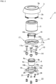
FIG. 2 is an exploded perspective view of an airbag module provided in the airbag device ofFIG. 1 ; -
FIG. 3 is an explanatory diagram of a damper unit provided in the airbag device ofFIG. 1 ; -
FIG. 4 is a cross-sectional view showing an assembled state of the airbag device provided in a steering wheel depicted inFIG. 1 ; -
FIG. 5 is a perspective view of an inflator and mounting member provided in the airbag module ofFIG. 2 in an assembled state; -
FIG. 6 is a side view of the assembled state depicted inFIG. 5 ; -
FIG. 7 is a rear view depicting a state in which a securing member is provided in the assembled state depicted inFIG. 5 ; -
FIG. 8 is a perspective view depicting a Modified Example of a mounting member provided in the airbag device provided in a steering wheel according to the present invention; -
FIG. 9 is a rear view of the assembled state depicted inFIG. 8 ; and -
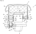
FIG. 10 is a cross-sectional view depicting an assembled state of an airbag device provided in a steering wheel, in accordance with the Modified Example ofFIG. 8 . - Hereinafter, preferred embodiments of an airbag device provided in a steering wheel according to the present invention will be described in detail with reference to the accompanying drawings.
-
FIG. 1 is a perspective view depicting an outline of an airbag device provided in a steering wheel according to the present Embodiment, in whichFIG. 1(a) depicts theentire steering wheel 1, andFIG. 1(b) depicts the disassembled state with anairbag module 2 removed from thesteering wheel 1. In the present specification, the side facing the driver is referred to as the front side, and the opposite side is referred to as the back side. - The
steering wheel 1 is installed at the driver's seat of the vehicle and is connected to a steering shaft that passes through the inside of a steering column, and transmits the steering operation of thesteering wheel 1 by the driver to a steering gear or the like. - A
steering wheel 1 contains a metal core metal member. The core metal member is composed of acenter boss part 6, anannular rim part 7 gripped by the driver, and spokeparts 8 that connect theboss part 6 andrim part 7. - The
boss part 6 has ashaft hole 9 formed that connects to the steering shaft. Theboss part 6 is also provided with threemounting holes 13 around theshaft hole 9, in which hollowcylindrical collar members 12 are disposed (seeFIG. 4 ). - The
steering wheel 1 is steered by arim part 7 that defines a steering surface, and the outer diameter of therim part 7 is the outer diameter of thesteering wheel 1. - An
airbag module 2 with a built-in airbag cushion is attached on thesteering wheel 1. - The side of the
airbag module 2 facing the driver is covered with ahorn cover 3. Thehorn cover 3 is composed of acover surface part 3a which is a design surface, and a hollowcylindrical part 3b which is integrally formed on the rear side of thecover surface part 3a (seeFIG. 2 andFIG. 4 ). Anairbag cushion 5 is stowed inside thecylindrical part 3b. - When inflator gas is supplied to the
airbag cushion 5 in the event of an emergency such as a collision, theairbag cushion 5 tears open thecover surface part 3a of thehorn cover 3 and expands and deploys toward the vehicle interior space to restrain and protect the driver. - The
airbag module 2 normally functions as a horn button that the driver presses toward thesteering wheel 1 for sounding the horn. - The
airbag module 2 further functions as a damper mass. For this reason, theairbag module 2 is provided with adamper unit 10 for damping the vibration of the steering wheel 1 (seeFIG. 2 to FIG. 4 ). -
FIG. 2 depicts an exploded perspective view of theairbag module 2. Theairbag module 2 includes ahorn cover 3, anairbag cushion 5, aninflator 4 that supplies inflator gas to the inside of theairbag cushion 5, and amodule base 15 for attaching and securing theinflator 4 and theairbag cushion 5. - The
module base 15 is composed of aretainer ring 16 for mounting theairbag cushion 5, a securingmember 17 formed of a plate material and overlapped on the back side of theretainer ring 16, and a mountingmember 18 formed of a plate material and further overlapped on the back side of the securingmember 17. The securingmember 17 and the mountingmember 18 are formed with bolt throughholes 18a through which thebolts 16a of theretainer ring 16 are inserted. - The mounting
member 18 has a circular through-hole part 19 formed at a center position thereof, to which theinflator 4 is attached, and three retainingparts 20 arranged surrounding the circular through-hole 19 (seeFIG. 4 andFIG. 7 ). In the present Embodiment, the retainingpart 20 is a through hole. - The securing
member 17 and theretainer ring 16 are formed withholes hole part 19 and serve to position theinflator 4 within theairbag cushion 5. - The
bolts 16a of theretainer ring 16 are inserted through the bolt throughholes 18a of the securingmember 17 and the mountingmember 18, andnuts 21 are fastened from the back side of the mountingmember 18, thereby assembling theinflator 4 and theairbag cushion 5 to themodule base 15. - Furthermore, the
cylindrical part 3b of thehorn cover 3, in which theairbag cushion 5 is stowed, is attached to themodule base 15. - The
airbag module 2 is constructed by assembling theairbag cushion 5, theinflator 4, and thehorn cover 3 to themodule base 15, and functions as a damper mass for damping vibrations. - The
damper unit 10 is provided between theairbag module 2 and thesteering wheel 1 as a functional component for damping vibrations transmitted between theairbag module 2 and thesteering wheel 1. - The
airbag module 2 is connected and attached to thesteering wheel 1 via thedamper unit 10. - As depicted in
FIG. 1 andFIG. 3 ,damper units 10 are arranged in three retaining parts (through holes) 20 of the mountingmember 18 that constitutes amodule base 12 of theairbag module 2. - As depicted in
FIGS. 2 to 4 , thedamper unit 10 is composed of a hollow cylindrical dampingmember 14 that is attached to the retainingpart 20 of the mountingmember 18, and a rod-shapedpin 11 that is slidably inserted into a dampingmember 14. Thepin 11 has a connectingtip part 11a at a first end part and abase plate part 11b at a second end part. The dampingmember 14 is configured to includerubber 51 that exhibits a vibration damping effect. -
FIG. 3(a) is a perspective view of thedamper unit 10, andFIG. 3(b) is an exploded perspective view of thedamper unit 10. - To briefly describe the configuration of the damping
member 14 that constitutes thedamper unit 10, the damping member is composed of anannular insulator 50 that is overlapped on thebase plate part 11b of thepin 11, anannular rubber 51 that surrounds thepin 11 and is overlapped on theannular insulator 50 and provides a vibration damping effect, acollar 52 that is formed in a cylindrical shape that surrounds thepin 11 so as to be able to slide freely, with atab part 52a engaging with theannular insulator 50 to clamp therubber 51, therubber 51 positioned on the outside, and aholder 53 that is formed in a cylindrical shape that surrounds the outside of therubber 51, is provided on thebase plate part 11b side of thepin 11, and holds therubber 51 to thepin 11. - The
collar 52 is provided with aspring seat 52b of thehorn spring 23, which will be described below. - When assembling the
damper unit 10, therubber 51 is inserted into theholder 53, theannular insulator 50 is overlapped on therubber 51, and theannular insulator 50 is engaged with thetab part 52a of thecollar 52 inserted from the opposite side of theholder 53, thereby completing the dampingmember 14. - A connecting tip part 12a of the
pin 11 is formed in a cone shape. Thepin 11 is pressed into thecollar 52 from the connecting tip part 12a side, and is fitted into the dampingmember 14 so as not to be removable. - The
pin 11 is connected to thesteering wheel 1 by inserting the longitudinal connectingtip part 11a having the narrowedpart 11d into thecollar member 12 and engaging the narrowedportion 11d with an engagingmember 22 provided on theboss part 6. - The
pin 11 is connected to theairbag module 2 by engaging thesecond end part 11b in the longitudinal direction, which has aflange part 11c, with the dampingmember 14 provided on the retainingpart 20 of the mountingmember 18. - A
horn spring 23 is provided between theboss part 6 of thesteering wheel 1 and the mountingmember 18 of themodule base 15 so as to surround thepin 11 and serve as an elastic member that is elastically deformable. Thehorn spring 23 elastically supports theairbag module 2 away from thesteering wheel 1. - The vibration of the
steering wheel 1 is transmitted to the dampingmember 14 via thepin 11. The dampingmember 14 dampens the vibrations of thesteering wheel 1 transmitted thereto, using theairbag module 2, to which the dampingmember 14 is attached, as a damper mass. - In addition, when the
airbag module 2 is pressed toward thesteering wheel 1 to operate the horn, thehorn spring 23 is elastically deformed, causing the dampingmember 14 to slide relative to thepin 11 connected to thesteering wheel 1, and themodule base 15 is moved toward thesteering wheel 1 together with the dampingmember 14. - Although not shown, horn contacts for sounding the horn are provided on the
pin 11 and themodule base 15, which come into contact with and are separated from each other. - In the airbag device provided in a steering wheel according to the present Embodiment, the
inflator 4 and thedamper unit 10, which is a functional component, are assembled to an mountingmember 18 having a unique configuration, as shown in detail inFIG. 4 to FIG. 7 . - The
inflator 4 is formed in a cylindrical shape. Theinflator 4 has anannular stopper 4b formed on a first end side having thegas discharge hole 4a, in other words, the end side opposite theboss part 6 which is inserted into theairbag cushion 5, protruding slightly in the radial direction of theinflator 4. - The mounting
member 18 is formed from a plate material. The mountingmember 18 is provided with a circular through-hole part 19 formed in a central position, three retainingparts 20 protruding radially outward from the circular through-hole part 19 and formed to match the arrangement of the threedamper units 10, and aflat part 24 formed connecting these retainingparts 20 and the circular through-hole part 19 to reinforce the retainingparts 20. - The circular through-
hole part 19 is composed of acircular hole 19a formed by penetrating the mountingmember 18 in the axial direction (length direction) of the cylindrical shapedinflator 4, and anannular rib 19b formed on the inner circumferential edge of thecircular hole 19a and raised in the axial direction of theinflator 4. - The
inflator 4 is press-fitted into thecircular hole 19a of the circular through-hole part 19 from the front side to the back side along the axial direction of theinflator 4, and theannular rib 19b is pressed against thecircumferential side surface 4c of theinflator 4. - As a result, the
inflator 4 is firmly secured to the circular through-hole part 19 of the mountingmember 18 by press-fitting. - The
annular stopper 4b of theinflator 4 assembled to the circular through-hole part 19 faces theannular rib 19b in the axial direction of theinflator 4 with a gap therebetween. - When the
inflator 4 discharges inflator gas from thegas discharge hole 4a, theannular rib 19b stops theinflator 4 from moving toward theboss part 6 through thecircular hole 19a, thereby preventing theinflator 4 from coming out of the mountingmember 18. - The mounting
member 18 is bent from the front side to the back side to form asolid wall 25 that enhances the strength of the mountingmember 18. - This
solid wall 25 forms aninner groove part 26 recessed toward the rear surface side, and the retainingpart 20 is formed in theinner groove part 26. - The damping
member 14 of thedamper unit 10 is engaged and held in the retainingpart 20 which is a through hole. - The engaging structure is such that both the retaining
part 20 in the form of a through hole and the dampingmember 14 are formed, for example, in an elliptical shape defined by a major axis and a minor axis, the major axes and minor axes of the retainingpart 20 and the dampingmember 14 are aligned with each other, the dampingmember 14 is inserted into the retainingpart 20, and then the dampingmember 14 is rotated so that the dampingmember 14 is engaged with the retainingpart 20. As a result, thedamper unit 10 is assembled to the mountingmember 18. - The
flat part 24 has aninner groove part 26 including the retainingpart 20 connected to the circular through-hole part 19 via thesolid wall 25, thereby connecting the retainingpart 20, which is cantilevered from the circular through-hole part 19, to the circular reinforcingpart 19 for reinforcement. - The circular through-
hole part 19, thesolid wall 25, theinner groove part 26, and the like of the mountingmember 18 can be formed by ordinary press molding of a plate material. - In the present Embodiment, as described with regards to
FIG. 2 , the plate-shaped securingmember 17 is overlapped over the mountingmember 18 from theairbag module 2 side, and thenut 21 is fastened to theretainer ring 16, whereby both the securingmember 17 and the mountingmember 18 are assembled and secured.FIG. 4 andFIG. 7 depict the state in which the securingmember 17 is assembled to the mountingmember 18. - The securing
member 17 is disk-shaped and sized to cover theinner groove part 26 of the mountingmember 18, with ahole part 17a formed in the center for passing theinflator 4 through, and an annularvertical wall part 17b formed at the outer edge position, raised toward the front side. - The
damper unit 10 has a connectingtip part 11a of apin 11 having a narrowedportion 11d held on thesteering wheel 1, and thesecond end part 11b of thepin 11 having aflange part 11c on theairbag module 2 side is positioned between the securingmember 17 and the mountingmember 18 by the securingmember 17 covering theinner groove part 26. - The mounting
member 18 is formed with anassembly protrusion 18b for alignment with the securingmember 17 when assembled, and the securingmember 17 is formed with an engaginghole 17c into which theassembly protrusion 18b fits. - Furthermore, an elastically deformable
engaging hook 3c formed on thecylindrical part 3b of thehorn cover 3 of theairbag module 2 is engaged with the engaginghole 17c of the securingmember 17. - By engaging the engaging
hook 3c with the engaginghole 17c, thehorn cover 3 housing theairbag cushion 5 is attached to the securingmember 17, that is, themodule base 15 on which theinflator 4 is provided. - The operation of the airbag device provided in a steering wheel according to the present Embodiment will be described.
- First, the
inflator 4 is attached to the circular through-hole part 19 of the mountingmember 18, and thedamper unit 10, which is a functional component, is attached to the retainingpart 20. - Next, the securing
member 17 is overlapped on the mountingmember 18 from the front side, and then theairbag cushion 5 with theretainer ring 16 attached is assembled from the front side by passing thebolt 16a of theretainer ring 16 through the bolt throughhole 18a of the securingmember 17 and the mountingmember 18, and secured by tightening thenut 21 onto thebolt 16a. - Next, the
horn cover 3 is attached to the securingmember 17. In this manner, theairbag module 2 is completed. - To attach the
airbag module 2 to thesteering wheel 1, thecollar member 12 is positioned in the mountinghole 13 of theboss part 6, thehorn spring 23 is disposed between thesteering wheel 1 and theairbag module 2, thepin 11 of thedamper unit 10 is inserted through thehorn spring 23 and into thecollar member 12, and the narrowedportion 11d of thepin 11 is engaged with the engagingmember 22. - This completes the installation of the
airbag module 2 onto thesteering wheel 1. - In the airbag device provided in a steering wheel of the present Embodiment, the
inflator 4 is cylindrical in shape and does not have a flange part, and the mountingmember 18 is formed with a circular through-hole part 19 into which theinflator 4 is fitted, and theinflator 4 is secured to the mountingmember 18 by being press-fitted therein. - This makes it possible to form the retaining
part 20 of thedamper unit 10, which is a functional component, so as to be positioned around theinflator 4 in close proximity to theinflator 4, eliminating the need for wasted space caused by the mounting piece in the background technology and allowing thedamper unit 10 to be brought closer to theinflator 4. - As a result, the installation space for the
inflator 4 and thedamper unit 10 can be narrowed and made compact with respect to the steering surface of thesteering wheel 1, and theairbag module 2 can be significantly reduced in size relative to the outer diameter of thesteering wheel 1. - An airbag device including such a
miniaturized airbag module 2 can be appropriately installed even on a non-circular or irregularly shapedsteering wheel 1. - The circular through-
hole part 19 is formed through the mountingmember 18 in the axial direction of theinflator 4, and is composed of acircular hole 19a into which theinflator 4 is fitted, and anannular rib 19b formed on the inner circumferential edge of thecircular hole 19a that is pressed against thecircumferential side surface 4c of theinflator 4, so that theinflator 4 can be firmly secured to the mountingmember 18. - Since the
inflator 4 can be firmly secured to the mountingmember 18 constituting themodule base 15, the inflator gas can be supplied to theairbag cushion 5 with a level comparable to that of the conventional technology. - Since the
inflator 4 is provided with theannular stopper 4b facing theannular rib 19b, theinflator 4 can be prevented from coming out of the mountingmember 18 when the inflator gas is ejected. - An
inner groove part 26 is formed in the mountingmember 18 by thesolid wall 25 that enhances the strength of the mountingmember 18, and a retainingpart 20 is formed within theinner groove part 26, thereby enhancing the strength of the entire mountingmember 18 to which theinflator 4 and thedamper unit 10 are assembled. - The
airbag module 2 is provided with a securingmember 17 which is placed over theairbag module 2 and secured to the mountingmember 18, and thedamper unit 10 holds thesecond end part 11b of thepin 11 between the securingmember 17 and the mountingmember 18, and holds the connectingtip part 11a on thesteering wheel 1. This ensures that the vibration damping effect of thedamper unit 10 is adequately achieved. - The
airbag module 2 is provided with ahorn cover 3 that covers theairbag cushion 5, and thehorn cover 3 is attached to the securingmember 17 that constitutes themodule base 15, so that theairbag module 2 can be constructed with a small number of parts. - The mounting
member 18 includes a circular through-hole part 19 formed in a central position, a retainingpart 20 formed at a position protruding radially outward from the circular through-hole part 19, aflat part 24 formed connecting between the retainingpart 20 and the circular through-hole part 19, and reinforcing the retainingpart 20, thereby further increasing the strength of the entire mountingmember 18 to which theinflator 4 and thedamper unit 10 are assembled. -
FIGS. 8 to 10 illustrate a Modified Example of the above Embodiment. In the above embodiment, the securingmember 17 is overlapped on the mountingmember 18, but in this Modified Example, the securingmember 17 is omitted, and thering retainer 16 is directly fastened to the mountingmember 18 with thenut 21. - The mounting
member 18 of this Modified Example is formed in a disk shape, and in the same manner as the mounting member of the above embodiment, is provided with a circular through-hole part 19, a retainingpart 20, and aflat part 24. In addition, at the outer edge position, an annular reinforcingwall part 27 is formed rising toward the front side, connected to theflat part 24 and the retainingpart 20 and surrounding theflat part 24 and the retainingpart 20. - By providing the annular reinforcing
wall part 27 facing theannular rib 19b in the radial direction of the mountingmember 18, the strength of the mountingmember 18 can be further increased. - The
annular wall part 27 is formed with avent piece 27a for engaging with an elastically deformableengaging hook 3c formed on thecylindrical part 3b of thehorn cover 3 of theairbag module 2. - By engaging the engaging
hook 3c with thevent piece 27a, thehorn cover 3 stowing theairbag cushion 5 is attached to the mountingmember 18, that is, themodule base 15 to which theinflator 4 is secured. - This Modified Example will of course exhibit the same function effect as the embodiment described above.
- In this Modified Example, the securing
member 17 is omitted, thereby making it possible to reduce the number of parts and the weight. - In the above embodiment, the
damper unit 10 has been described as an example of a functional component, but it goes without saying that the functional component is not limited to thedamper unit 10 and may be other functional components that are assembled to the mountingmember 18, such as other horn parts. - The airbag device provided in a steering wheel described above is a preferred example of the present invention, and other embodiments can be implemented or performed in various ways. In particular, unless otherwise described in the specification of the application, the invention is not restricted to the shapes, sizes, configurational dispositions, and the like of the parts illustrated in detail in the accompanying drawings. In addition, the expressions and terms used in the specification of the application are used for providing a description, without limiting the invention thereto, unless specifically described otherwise.
-
- 1. Steering wheel
- 2. Airbag module
- 3. Horn cover
- 4. Inflator
- 4b. Annular stopper
- 4c Circumferential side surface of inflator
- 5. Airbag cushion
- 10. Damper unit
- 17. Securing member
- 18. Mounting member
- 19. Circular through-hole part
- 19a. Circular hole
- 19b. Annular rib
- 20. Retaining part
- 23. Horn spring
- 24. Flat part
- 25. Solid wall
- 26. Inner groove part
- 27. Reinforcing wall part
Claims (10)
- An airbag device provided in a steering wheel, comprising:an airbag module containing an airbag cushion and a cylindrical shaped inflator that supplies inflator gas to the airbag cushion;a functional component provided between the airbag module and the steering wheel; anda mounting member formed of a plate material to which the inflator and the functional component are assembled, whereinthe mounting member has formed thereon:a circular through-hole part into which the inflator is press-fit to secure the inflator; anda retaining part for retaining the functional component.
- The airbag device provided in a steering wheel according to claim 1, wherein the circular through-hole part includes:a circular hole formed in the mounting member penetrating in the axial direction perpendicular to the center of the bottom surface of the inflator and into which the inflator is pressed; andan annular rib formed on the inner circumferential edge of the circular hole and pressed onto the circumferential side surface of the inflator.
- The airbag device provided in a steering wheel according to claim 2, wherein an annular stopper is provided on the outer circumferential portion of the inflator between the annular rib and the gas discharge hole of the inflator.
- The airbag device provided in a steering wheel according to claim 1, wherein the mounting member is provided with a flat part on an outer circumference of the circular through-hole part, and the retaining part is provided so as to have a step with regard to the flat part.
- The airbag device provided in a steering wheel according to claim 4, wherein the step is characterized by a vertical wall extending from the flat part forming an inner groove part and the retaining part being formed on this inner groove part.
- The airbag device provided in a steering wheel according to any one of claims 1 to 5, wherein the functional component is a damper unit that dampens vibration transmitted between the airbag module and the steering wheel, is provided between the mounting member and the steering wheel, and includes an elastic member that elastically holds the airbag module on the steering wheel.
- The airbag device provided in a steering wheel according to claim 1 or 2, wherein the airbag module is provided with a securing member attached and secured to the mounting member, covering the airbag module, the first end of the functional component is held between the securing member and the mounting member, and the second end is held on the steering wheel.
- The airbag device provided in a steering wheel according to claim 7, wherein the airbag module is provided with a cover for covering the airbag cushion and this cover is attached to the securing member.
- The airbag device provided in a steering wheel according to claim 8, wherein the mounting member is provided with an annular reinforcing wall part surrounding the flat part and the retaining part.
- The airbag device provided in a steering wheel according to claim 9, wherein the airbag module is provided with a cover for covering the airbag cushion and this cover is attached to the reinforcing wall part.
Applications Claiming Priority (2)
| Application Number | Priority Date | Filing Date | Title |
|---|---|---|---|
| JP2022109561 | 2022-07-07 | ||
| PCT/JP2023/024622 WO2024009952A1 (en) | 2022-07-07 | 2023-07-03 | Airbag device provided to steering wheel |
Publications (2)
| Publication Number | Publication Date |
|---|---|
| EP4538125A1 true EP4538125A1 (en) | 2025-04-16 |
| EP4538125A4 EP4538125A4 (en) | 2025-12-31 |
Family
ID=89453333
Family Applications (1)
| Application Number | Title | Priority Date | Filing Date |
|---|---|---|---|
| EP23835484.9A Pending EP4538125A4 (en) | 2022-07-07 | 2023-07-03 | Airbag device provided to steering wheel |
Country Status (6)
| Country | Link |
|---|---|
| US (1) | US12673631B2 (en) |
| EP (1) | EP4538125A4 (en) |
| JP (1) | JP7846766B2 (en) |
| KR (1) | KR20250034378A (en) |
| CN (1) | CN119421817A (en) |
| WO (1) | WO2024009952A1 (en) |
Family Cites Families (16)
| Publication number | Priority date | Publication date | Assignee | Title |
|---|---|---|---|---|
| JPH04292238A (en) * | 1991-03-19 | 1992-10-16 | Achilles Corp | Air bag for vehicle |
| DE19955426B4 (en) * | 1999-11-18 | 2005-11-10 | Carl Freudenberg Kg | Gas generator for an airbag |
| US20030201629A1 (en) * | 2002-04-26 | 2003-10-30 | Naoki Matsuda | Method of inflating air bag |
| KR100616437B1 (en) * | 2005-01-10 | 2006-08-29 | 델파이코리아 주식회사 | Airbag Module Device |
| JP4733168B2 (en) | 2008-09-16 | 2011-07-27 | 豊田合成株式会社 | Steering wheel with airbag device |
| US8029017B2 (en) * | 2009-01-22 | 2011-10-04 | Toyoda Gosei Co. Ltd. | Airbag inflator manifold |
| JP5392909B2 (en) | 2009-09-25 | 2014-01-22 | 日本プラスト株式会社 | Airbag device |
| JP5357712B2 (en) * | 2009-11-18 | 2013-12-04 | 日本プラスト株式会社 | Airbag device |
| JP6040884B2 (en) * | 2012-11-12 | 2016-12-07 | 豊田合成株式会社 | Steering wheel damping structure |
| JP6085453B2 (en) * | 2012-11-13 | 2017-02-22 | タカタ株式会社 | Airbag device |
| JP6014559B2 (en) * | 2013-07-31 | 2016-10-25 | タカタ株式会社 | Inflator mounting structure and airbag device |
| JP6215646B2 (en) * | 2013-10-22 | 2017-10-18 | 株式会社ダイセル | Inflator and airbag fixing structure |
| JP6434699B2 (en) * | 2014-02-18 | 2018-12-05 | Joyson Safety Systems Japan株式会社 | Airbag device |
| EP2995512B1 (en) * | 2014-09-11 | 2017-11-15 | Dalphi Metal España, S.A. | Airbag module, retainer and assembly of airbag module and steering wheel |
| JP6905548B2 (en) * | 2018-07-11 | 2021-07-21 | オートリブ ディベロップメント エービー | Steering wheel damper mechanism and vehicle steering wheel device |
| EP3922536B1 (en) | 2019-02-08 | 2023-12-06 | Autoliv Development AB | Vibration reduction structure for vehicle steering wheel |
-
2023
- 2023-07-03 EP EP23835484.9A patent/EP4538125A4/en active Pending
- 2023-07-03 KR KR1020257000465A patent/KR20250034378A/en active Pending
- 2023-07-03 WO PCT/JP2023/024622 patent/WO2024009952A1/en not_active Ceased
- 2023-07-03 CN CN202380049476.1A patent/CN119421817A/en active Pending
- 2023-07-03 JP JP2024532125A patent/JP7846766B2/en active Active
- 2023-07-03 US US18/992,006 patent/US12673631B2/en active Active
Also Published As
| Publication number | Publication date |
|---|---|
| WO2024009952A1 (en) | 2024-01-11 |
| US20260014952A1 (en) | 2026-01-15 |
| CN119421817A (en) | 2025-02-11 |
| EP4538125A4 (en) | 2025-12-31 |
| US12673631B2 (en) | 2026-07-07 |
| KR20250034378A (en) | 2025-03-11 |
| JPWO2024009952A1 (en) | 2024-01-11 |
| JP7846766B2 (en) | 2026-04-15 |
Similar Documents
| Publication | Publication Date | Title |
|---|---|---|
| US11034374B2 (en) | Steering wheel | |
| EP3812240B1 (en) | Structure for mounting and fixing damper unit in steering wheel, and steering wheel | |
| KR102610029B1 (en) | steering wheel | |
| USRE47687E1 (en) | Damping system for steering wheel | |
| US5508482A (en) | Horn activation and steering wheel assembly | |
| US8985623B2 (en) | Steering wheel structure with airbag module | |
| US8459686B2 (en) | Steering wheel with airbag device | |
| US12612104B2 (en) | Steering wheel device for vehicle | |
| JP6783986B2 (en) | Steering wheel | |
| JP2002120730A (en) | Mounting structure of steering switch | |
| JP6673752B2 (en) | handle | |
| CN116917186A (en) | steering wheel | |
| US7268309B2 (en) | Horn switch gear and airbag system | |
| CN114750720B (en) | Support structure of air bag device | |
| US20260014952A1 (en) | Airbag device provided to steering wheel | |
| EP4365059A1 (en) | Steering wheel device for vehicle | |
| US20230406252A1 (en) | Steering wheel and method of manufacturing same | |
| US12202425B2 (en) | Coupling device for securing an airbag module to a vehicle steering wheel | |
| JPH09175411A (en) | Vehicle steering wheel | |
| JP7410308B2 (en) | vehicle steering wheel device | |
| EP4559780A1 (en) | Structure for attaching airbag module to steering wheel | |
| US12252089B2 (en) | Steering wheel | |
| JP2816306B2 (en) | Steering wheel | |
| US20260138663A1 (en) | Vehicle steering wheel device | |
| JP2001047957A (en) | Airbag device |
Legal Events
| Date | Code | Title | Description |
|---|---|---|---|
| STAA | Information on the status of an ep patent application or granted ep patent |
Free format text: STATUS: THE INTERNATIONAL PUBLICATION HAS BEEN MADE |
|
| PUAI | Public reference made under article 153(3) epc to a published international application that has entered the european phase |
Free format text: ORIGINAL CODE: 0009012 |
|
| STAA | Information on the status of an ep patent application or granted ep patent |
Free format text: STATUS: REQUEST FOR EXAMINATION WAS MADE |
|
| 17P | Request for examination filed |
Effective date: 20250107 |
|
| AK | Designated contracting states |
Kind code of ref document: A1 Designated state(s): AL AT BE BG CH CY CZ DE DK EE ES FI FR GB GR HR HU IE IS IT LI LT LU LV MC ME MK MT NL NO PL PT RO RS SE SI SK SM TR |
|
| DAV | Request for validation of the european patent (deleted) | ||
| DAX | Request for extension of the european patent (deleted) | ||
| A4 | Supplementary search report drawn up and despatched |
Effective date: 20251202 |
|
| RIC1 | Information provided on ipc code assigned before grant |
Ipc: B60R 21/203 20060101AFI20251126BHEP Ipc: B60R 21/217 20110101ALI20251126BHEP Ipc: B62D 1/10 20060101ALI20251126BHEP Ipc: B62D 7/22 20060101ALI20251126BHEP |