EP4538124A1 - Improved roof safety assembly for a work vehicle - Google Patents
Improved roof safety assembly for a work vehicle Download PDFInfo
- Publication number
- EP4538124A1 EP4538124A1 EP24205667.9A EP24205667A EP4538124A1 EP 4538124 A1 EP4538124 A1 EP 4538124A1 EP 24205667 A EP24205667 A EP 24205667A EP 4538124 A1 EP4538124 A1 EP 4538124A1
- Authority
- EP
- European Patent Office
- Prior art keywords
- support structure
- impact
- safety assembly
- roof safety
- absorbing
- Prior art date
- Legal status (The legal status is an assumption and is not a legal conclusion. Google has not performed a legal analysis and makes no representation as to the accuracy of the status listed.)
- Granted
Links
Images


Classifications
-
- B—PERFORMING OPERATIONS; TRANSPORTING
- B62—LAND VEHICLES FOR TRAVELLING OTHERWISE THAN ON RAILS
- B62D—MOTOR VEHICLES; TRAILERS
- B62D33/00—Superstructures for load-carrying vehicles
- B62D33/06—Drivers' cabs
- B62D33/0617—Drivers' cabs for tractors or off-the-road vehicles
- B62D33/0625—Drivers' cabs for tractors or off-the-road vehicles open
-
- B—PERFORMING OPERATIONS; TRANSPORTING
- B60—VEHICLES IN GENERAL
- B60R—VEHICLES, VEHICLE FITTINGS, OR VEHICLE PARTS, NOT OTHERWISE PROVIDED FOR
- B60R21/00—Arrangements or fittings on vehicles for protecting or preventing injuries to occupants or pedestrians in case of accidents or other traffic risks
- B60R21/02—Occupant safety arrangements or fittings, e.g. crash pads
- B60R21/13—Roll-over protection
- B60R21/131—Protective devices for drivers in case of overturning of tractors
Definitions
- the present invention concerns a roof safety assembly for a work vehicle, and a work vehicle comprising such roof safety assembly.
- an agricultural vehicle such as a tractor
- a tractor is subject to the risk of rollover.
- An aim of the present invention is to satisfy the aforementioned need in a cost-effective and optimised manner.
- the vehicle 1 comprises a pair of front wheels 6 arranged in the front portion 3 and a pair of rear wheels 7 arranged in the rear portion 4.
- the roof 14 extends substantially parallel to the longitudinal axis A, and is substantially parallel to the floor 11.
- the plurality of elements 15 may comprise roller blinds.
- the cabin 5 is configured to house a seat 21 for an occupant O of the cabin, and comprises a plurality of windowed areas 22 allowing the occupant O to see outside the cabin 5.
- the roof safety assembly 31 is arranged on the side of the roof 14 facing the floor 11, and preferably near the elements 15 of the roof assembly 13.
- the roof safety assembly 31 is configured to be carried by the pillars 12.
- the impact-absorbing means 42 are connected to the support structure 41 and at least partially surround the perimeter of the support structure 41.
- the impact-absorbing means 42 are detachably connected to, i.e. detachable from, the support structure 41, as described in detail hereinafter.
- the support structure 41 defines a region R and the impact-absorbing means 42 extend externally to the region R.
- the support structure 41 defines a longitudinal axis B and comprises a front portion 51 intersecting the longitudinal axis B and two side portions 52 extending from opposite sides with respect to the longitudinal axis B.
- the front portion 51 is configured to be connected to a front portion 61 of the cabin 5 and the two side portions 52 are configured to be connected to respective side portions 62 of the cabin 5.
- the impact-absorbing means 42 are configured to surround at least one of the two side portions 52 of the support structure 41.
- the support structure 41 is symmetrical with respect to a plane parallel to the longitudinal axis B and orthogonal to the quadrilateral.
- each deformable element 91 is configured to absorb energy by deforming in case of impact of the vehicle 1 with the ground G.
- each deformable element 91 comprises an accordion-shaped element 92.
- each element 92 is shaped as an accordion so as to absorb energy quickly and gradually, by progressively closing in case of impact of the vehicle 1 with the ground G.
- each accordion-shaped element 92 is made of metal.
- the accordion-shaped elements 92 have substantially the same shape.
- the impact-absorbing means 42 comprise connecting means 93 configured to connect the two deformable elements 91.
- the connecting means 93 are more rigid than the deformable elements 91.
- the bar 94 is a metal bar which is more rigid, i.e. less easily deformable, than the two deformable elements 91.
- each deformable element 91 of each impact-absorbing structure 101 is configured to be connected to the support structure 41.
- each deformable element 91 of each impact-absorbing structure 101 comprises the aforementioned accordion-shaped element 92.
- the two deformable elements 91 of each impact-absorbing structure 101 are connected by the aforementioned connecting means 93, which are more rigid than the deformable elements 91.
- each impact-absorbing structure 101 comprises the aforementioned bar 94, i.e. each impact-absorbing structure 101 comprises a respective bar 94.
- the bar 94 of each impact-absorbing structure 101 extends substantially parallel to the respective side portion 52 of the support structure 41.
- the two deformable elements 91 of each impact-absorbing structure 101 are connected by the respective bar 94, which is substantially parallel to the respective side portion 52 of the support structure 41.
- the bar 94 is configured to transmit energy to the two deformable elements 91 of the respective impact-absorbing structure 101 in case of impact of the vehicle 1 with the ground G, so that both deformable elements 91 of the respective impact-absorbing structure 101 can absorb energy in case of impact of the vehicle 1 with the ground G.
- the bar 94 is more rigid, i.e. less easily deformable, than the two deformable elements 91 of the respective impact-absorbing structure 101.
- the bar 94 comprises two end portions which are bent, e.g. orthogonally, towards the two deformable elements 91 of the respective impact-absorbing structure 101.
- each impact-absorbing structure 101 comprises two intermediate elements 121.
- Each intermediate element 121 is interposed between one of the aforementioned coupling elements 111 and one of the aforementioned deformable elements 91.
- each intermediate element 121 extends substantially parallel to the front portion 51 of the support structure 41.
- the roof safety assembly 31 comprises a subframe 131 configured to be carried by the support structure 41, and one or more airbags 141 configured to be carried by the subframe 131.
- the subframe 131 is detachably connected to, i.e. detachable from, the support structure 41.
- the subframe 131 extends internally to the region R.
- each bracket 141 is configured to carry a respective airbag 141.
- the subframe 131 comprises a front portion 161 intersecting the longitudinal axis B and two side portions 162 extending from opposite sides with respect to the longitudinal axis B.
- the front portion 161 of the subframe 131 faces the front portion 51 of the support structure 41, while the two side portions 162 of the subframe 131 face the respective side portions 52 of the support structure 41.
- the subframe 131 comprises a rear portion 171 connected to the side portions 162 of the subframe.
- the front portion 161, the side portions 162 and the rear portion 171 of the subframe 131 define a quadrilateral which extends internally to the region R and extends parallel to the longitudinal axis B.
- the quadrilateral is a trapezium
- the front portion 161 and the rear portion 171 of the subframe 131 substantially correspond to the parallel edges of the trapezium.
- the trapezium is isosceles, i.e. the side portions 162 of the subframe 131 have substantially the same length.
- the trapezium may be a rectangle, such as a square.
- the front portion 161 of the subframe 131 extends substantially orthogonally to the longitudinal axis B.
- the subframe 131 comprises connecting portions 181 configured to connect the subframe 131 to the support structure 41.
- each connecting portion 181 is configured to be connected to the support structure 41 via a detachable connection, preferably via threaded elements such as screws.
- Each connecting portion 181 is connected to at least one of the front portion 161, the side portions 162 and the rear portion 171 of the subframe 131.
- each connecting portion 181 extends from a respective corner of the quadrilateral defined by the front portion 161, the side portions 162 and the rear portion 171 of the subframe 131.
- the subframe 131 comprises an intermediate portion 191 which is interposed between the side portions 162 of the subframe 131, connects the front portion 161 and the rear portion 171 of the subframe 131 and is preferably parallel to the longitudinal axis B.
- the subframe 131 extends substantially parallel to the roof 14, i.e. the quadrilateral defined by the front portion 161, the side portions 162 and the rear portion 171 of the subframe 131 is substantially parallel to the roof 14.
- the subframe 131 is substantially coplanar to the support structure 41.
- the impact-absorbing means 42 in particular the two impact-absorbing structures 101, are connected, preferably detachably, to the support structure 41.
- the subframe 131 is connected, preferably detachably, to the support structure 41.
- the impact-absorbing means 42 which surround at least a portion of a perimeter of the support structure 41, absorb the energy transmitted by the impact of the cabin 5 with the ground G, thus reducing the energy transmitted to the support structure 41 and in turn to the cabin 5.
- the deformable elements 91 of the impact-absorbing structures 101 are connected to the respective coupling elements 111 via the respective intermediate elements 121 which extend substantially parallel to the front portion 51 of the support structure 41.
- the deformable elements 91 of the impact-absorbing structures 101 absorb the energy transmitted by the bars 94, which are substantially parallel to the respective side portions 52 of the support structure 41.
- each airbag 141 carried by the subframe 131, is automatically inflated in case of impact of the vehicle 1 with the ground G and further protects the occupant O.
- the deformable elements 91 allow to absorb energy by deforming.
- the accordion-shaped elements 92 allow to absorb energy quickly and gradually, by progressively closing.
- the connecting means 93 allow to transmit energy to the two deformable elements 91, so that both deformable elements 91 can absorb energy, by ensuring better contact with the ground G. This is especially useful if the soil is soft.
- the two impact-absorbing structures 101 allow to effectively absorb energy in case of side rollovers (also known as “roll-on-side”) since they surround, respectively, the two side portions 52 of the support structure 41.
- the coupling elements 111, the intermediate elements 121 carried by the coupling elements 111, the deformable elements 91 carried by the intermediate elements 121, and the bars 94 connecting the deformable elements 121 jointly allow to absorb the energy transmitted by the impact of the cabin 5 with the ground G, thus reducing the energy transmitted to the support structure 41 and in turn to the cabin 5.
- each airbag 141 carried by the subframe 131, allows to further protect the occupant O in case of impact of the vehicle 1 with the ground G.
- roof safety assembly 31 can be integrated on the cabin 5 of an existing vehicle 1 unprovided therewith, thus acting as a retrofit.
- the roof safety assembly 31 is detachably connected to, i.e. detachable from, the pillars 12. Therefore, if only the roof safety assembly 31 is damaged, the roof safety assembly 31 can be detached from the pillars 12 and replaced.
- each impact-absorbing structure 101 is detachably connected to, i.e. detachable from, the support structure 41. Therefore, if only the impact-absorbing structures 101 are damaged, the impact-absorbing structures 101 can be detached from the support structure 41 and replaced. Conveniently, if only one impact-absorbing structure 101 is damaged, such impact-absorbing structure 101 can be detached from the support structure 41 and replaced.
- the shape of the components may be different from that described.
Landscapes
- Engineering & Computer Science (AREA)
- Mechanical Engineering (AREA)
- Chemical & Material Sciences (AREA)
- Combustion & Propulsion (AREA)
- Transportation (AREA)
- Body Structure For Vehicles (AREA)
Abstract
Description
- The present invention concerns a roof safety assembly for a work vehicle, and a work vehicle comprising such roof safety assembly.
- The present invention finds its preferred, although not exclusive, application in an agricultural vehicle, such as a tractor.
- As is known, an agricultural vehicle, such as a tractor, is subject to the risk of rollover.
- In particular, it is estimated that at least one in ten operators will overturn a tractor in their lifetime. Tractor rollovers are the main cause of fatal accidents on several farms. The probability of the operator dying in case of a tractor rollover increases if the operator is unbelted. Eighty per cent of tractor rollover fatalities also involve experienced operators.
- Furthermore, even when the operator survives, the tractor cabin is severely damaged after a rollover.
- Therefore, the need is felt to improve safety and robustness of known work vehicles.
- An aim of the present invention is to satisfy the aforementioned need in a cost-effective and optimised manner.
- The aforementioned aim is reached by a roof safety assembly and a work vehicle as claimed in the appended set of claims.
- For a better understanding of the present invention, a preferred embodiment is described in the following, by way of a non-limiting example, with reference to the attached drawings wherein:
-
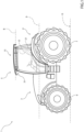
figure 1 is a side view of a work vehicle comprising a roof safety assembly according to the invention; -
figure 2 is a schematic cross-sectional view of a cabin of the work vehicle offigure 1 , with parts removed for the sake of clarity; -
figure 3 is a perspective view of the cabin offigure 2 , with parts removed for the sake of clarity; -
figure 4 is a perspective view of the roof safety assembly according to the invention; and -
figure 5 is an exploded perspective view of the roof safety assembly offigure 4 . -
Figure 1 illustrates a work vehicle 1 according to the present invention. Preferably, the vehicle 1 is an agricultural vehicle, such as a tractor. - The vehicle 1 is of known type, extends along a longitudinal axis A and comprises a
front portion 3, a rear portion 4, and acabin 5 longitudinally interposed between thefront portion 3 and the rear portion 4. - Conveniently, the vehicle 1 comprises a pair of front wheels 6 arranged in the
front portion 3 and a pair ofrear wheels 7 arranged in the rear portion 4. - Conveniently, the
cabin 5 comprises afloor 11, a plurality of pillars 12 and aroof assembly 13 carried by the plurality of pillars 12. - In particular, the plurality of pillars 12 comprises two front pillars 12a, connected to the
front portion 3 of the vehicle 1, and two rear pillars 12b, connected to the rear portion 4 of the vehicle 1. Thefloor 11 extends substantially parallel to the longitudinal axis A, while the two front pillars 12a and the two rear pillars 12b are inclined, e.g. orthogonal, with respect to the longitudinal axis A. - Conveniently, the
roof assembly 13 comprises aroof 14 configured to cover thecabin 5 and a plurality ofelements 15 arranged on the side of theroof 14 facing thefloor 11. - In particular, the
roof 14 extends substantially parallel to the longitudinal axis A, and is substantially parallel to thefloor 11. The plurality ofelements 15 may comprise roller blinds. - Conveniently, the
cabin 5 is configured to house aseat 21 for an occupant O of the cabin, and comprises a plurality of windowed areas 22 allowing the occupant O to see outside thecabin 5. - In particular, the
seat 21 is carried by thefloor 11, and the plurality of windowed areas 22 comprise a front windowed area 22a, arranged between the two front pillars 12a, and two side windowed areas 22b, each arranged between a respective front pillar 12a and a respective rear pillar 12b. - The vehicle 1 comprises a
roof safety assembly 31, as described in detail hereinafter. Preferably, theroof safety assembly 31 is interposed between the pillars 12 and theroof 14. - In particular, the
roof safety assembly 31 is arranged on the side of theroof 14 facing thefloor 11, and preferably near theelements 15 of theroof assembly 13. - Conveniently, the
roof safety assembly 31 is configured to be carried by the pillars 12. - Preferably, the
roof safety assembly 31 is detachably connected to, i.e. detachable from, the pillars 12. - In particular, the
roof safety assembly 31 is configured to be connected to the pillars 12 via a detachable connection, preferably via threaded elements such as screws. - The roof safety assembly 31 (
figures 4 and5 ) comprises asupport structure 41 configured to be connected to thecabin 5 and impact-absorbingmeans 42 configured to absorb energy in case of impact of the vehicle 1 with ground G. The impact-absorbingmeans 42 are configured to be carried by thesupport structure 41 and surround at least a portion of a perimeter of thesupport structure 41. - In particular, the impact-absorbing
means 42 are connected to thesupport structure 41 and at least partially surround the perimeter of thesupport structure 41. Preferably, the impact-absorbingmeans 42 are detachably connected to, i.e. detachable from, thesupport structure 41, as described in detail hereinafter. - Preferably, the
support structure 41 defines a region R and the impact-absorbing means 42 extend externally to the region R. - In particular, the perimeter of the
support structure 41 defines the region R and the impact-absorbingmeans 42 extends externally thereto. In other words, the impact-absorbing means 42 extend outwards from thesupport structure 41. Preferably, the region R is convex. - Preferably (
figure 3 ), thesupport structure 41 defines a longitudinal axis B and comprises afront portion 51 intersecting the longitudinal axis B and twoside portions 52 extending from opposite sides with respect to the longitudinal axis B. Thefront portion 51 is configured to be connected to afront portion 61 of thecabin 5 and the twoside portions 52 are configured to be connected torespective side portions 62 of thecabin 5. The impact-absorbingmeans 42 are configured to surround at least one of the twoside portions 52 of thesupport structure 41. - In particular, the
front portion 51 of thesupport structure 41 intersects the longitudinal axis B, whereas the twoside portions 52 of thesupport structure 41 do not intersect the longitudinal axis B. In use, the longitudinal axis B is parallel to the longitudinal axis A of the vehicle 1. Conveniently, thefront portion 61 of thecabin 5 faces thefront portion 3 of the vehicle 1, while theside portions 62 of thecabin 5 extend sideways. Preferably, thefront portion 51 of thesupport structure 41 is interposed between theroof 14 and the front windowed area 22a, while theside portions 52 of thesupport structure 41 are interposed between theroof 14 and the respective side windowed areas 22b. Conveniently, at least one of the twoside portions 52 of thesupport structure 41 is interposed between the longitudinal axis B and the impact-absorbingmeans 42. Preferably, eachside portion 52 of thesupport structure 41 is interposed between the longitudinal axis B and the impact-absorbingmeans 42, i.e. the impact-absorbing means 42 surround bothside portions 52 of thesupport structure 41. - Preferably, the
support structure 41 comprises aframe 71 substantially shaped as a quadrilateral. Thefront portion 51 of thesupport structure 41 substantially corresponds to a front edge of the quadrilateral and the twoside portions 52 of thesupport structure 41 substantially correspond to side edges of the quadrilateral connected to the front edge. Conveniently, thesupport structure 41 comprises arear portion 81 which substantially corresponds to the fourth edge of the quadrilateral and is connected to the side edges of the quadrilateral. - In particular, the
support structure 41 is hollow. Thefront portion 51 and theside portions 52, as well as therear portion 81, of thesupport structure 41 are elongated elements, such as beams. The shape of theframe 71 is substantially a quadrilateral which defines the region R and extends parallel to the longitudinal axis B. Preferably, the quadrilateral is a trapezium, and thefront portion 51 and therear portion 81 of thesupport structure 41 substantially correspond to the parallel edges of the trapezium. Preferably, the trapezium is isosceles, i.e. theside portions 52 of thesupport structure 41 have substantially the same length. In particular, the trapezium may be a rectangle, such as a square. Preferably, thefront portion 51 of thesupport structure 41 extends substantially orthogonally to the longitudinal axis B. - Preferably, the
support structure 41 extends substantially parallel to theroof 14, i.e. the quadrilateral is substantially parallel to theroof 14. Conveniently, thesupport structure 41 is substantially coplanar to theroof assembly 13. - Conveniently, the
support structure 41 is symmetrical with respect to a plane parallel to the longitudinal axis B and orthogonal to the quadrilateral. - Conveniently, the
support structure 41 is made of metal. - Preferably, the impact-absorbing
means 42 comprise twodeformable elements 91. Eachdeformable element 91 is configured to be connected to thesupport structure 41. - In particular, each
deformable element 91 is configured to absorb energy by deforming in case of impact of the vehicle 1 with the ground G. - Conveniently, the
deformable elements 91 have substantially the same shape. - Preferably, each
deformable element 91 comprises an accordion-shaped element 92. - In particular, each element 92 is shaped as an accordion so as to absorb energy quickly and gradually, by progressively closing in case of impact of the vehicle 1 with the ground G. Preferably, each accordion-shaped element 92 is made of metal.
- Conveniently, the accordion-shaped elements 92 have substantially the same shape.
- Preferably, the impact-absorbing
means 42 comprise connectingmeans 93 configured to connect the twodeformable elements 91. The connecting means 93 are more rigid than thedeformable elements 91. - In particular, the connecting
means 93 are configured to transmit energy to the twodeformable elements 91 in case of impact of the vehicle 1 with the ground G, so that bothdeformable elements 91 can absorb energy in case of impact of the vehicle 1 with the ground G. Conveniently, the connectingmeans 93 are more rigid, i.e. less easily deformable, than thedeformable elements 91. - Preferably, the connecting
means 93 comprise abar 94. - In particular, the
bar 94 is a metal bar which is more rigid, i.e. less easily deformable, than the twodeformable elements 91. - Preferably, the impact-absorbing
means 42 comprise two impact-absorbingstructures 101. Each impact-absorbingstructure 101 comprises two of the aforementioneddeformable elements 91. - In particular, each
deformable element 91 of each impact-absorbingstructure 101 is configured to be connected to thesupport structure 41. Preferably, eachdeformable element 91 of each impact-absorbingstructure 101 comprises the aforementioned accordion-shaped element 92. Conveniently, the twodeformable elements 91 of each impact-absorbingstructure 101 are connected by the aforementioned connectingmeans 93, which are more rigid than thedeformable elements 91. - Conveniently, the impact-absorbing
structures 101 have substantially the same shape. - Preferably, the two impact-absorbing
structures 101 are configured to surround, respectively, the twoside portions 52 of thesupport structure 41. - In particular, each
side portion 52 of thesupport structure 41 is interposed between the longitudinal axis B and a respective impact-absorbingstructure 101, i.e. eachside portion 52 of thesupport structure 41 faces the respective impact-absorbingstructure 101. In other words, each impact-absorbingstructure 101 is configured to surround arespective side portion 52 of thesupport structure 41. - Preferably, each impact-absorbing
structure 101 comprises theaforementioned bar 94, i.e. each impact-absorbingstructure 101 comprises arespective bar 94. Thebar 94 of each impact-absorbingstructure 101 extends substantially parallel to therespective side portion 52 of thesupport structure 41. - In particular, the two
deformable elements 91 of each impact-absorbingstructure 101 are connected by therespective bar 94, which is substantially parallel to therespective side portion 52 of thesupport structure 41. Thebar 94 is configured to transmit energy to the twodeformable elements 91 of the respective impact-absorbingstructure 101 in case of impact of the vehicle 1 with the ground G, so that bothdeformable elements 91 of the respective impact-absorbingstructure 101 can absorb energy in case of impact of the vehicle 1 with the ground G. Conveniently, thebar 94 is more rigid, i.e. less easily deformable, than the twodeformable elements 91 of the respective impact-absorbingstructure 101. Preferably, thebar 94 comprises two end portions which are bent, e.g. orthogonally, towards the twodeformable elements 91 of the respective impact-absorbingstructure 101. - Preferably, each impact-absorbing
structure 101 comprises twocoupling elements 111 corresponding to respective corners of the aforementioned quadrilateral and configured to be connected to respective ends of therespective side portion 52 of thesupport structure 41. - In particular, the impact-absorbing
means 42 comprise fourcoupling elements 111, two for each impact-absorbingstructure 101. The fourcoupling elements 111 define respective angular portions of thesupport structure 41 which substantially correspond to the four corners of the quadrilateral. Eachcoupling element 111 of each impact-absorbingstructure 101 is configured to be connected to a respective end of theside portion 52 surrounded by the impact-absorbingstructure 101. - Conveniently, each
coupling element 111 of each impact-absorbingstructure 101 is also configured to be connected to a respective end of either thefront portion 51 of thesupport structure 41 or therear portion 81 of thesupport structure 41. In other words, twocoupling elements 111 are configured to be connected to a respective end of thefront portion 51 of thesupport structure 41 and to a respective end of therespective side portion 52 of thesupport structure 41, and twocoupling elements 111 are configured to be connected to a respective end of therear portion 81 of thesupport structure 41 and to a respective end of therespective side portion 52 of thesupport structure 41. - Conveniently, the
coupling elements 111 have substantially the same shape. - Preferably, each impact-absorbing
structure 101 comprises twointermediate elements 121. Eachintermediate element 121 is interposed between one of theaforementioned coupling elements 111 and one of the aforementioneddeformable elements 91. - In particular, the impact-absorbing
means 42 comprise fourintermediate elements 121, two for each impact-absorbingstructure 101. Eachdeformable element 91 of each impact-absorbingstructure 101 is connected to therespective coupling element 111 via the respectiveintermediate element 121. Preferably, eachintermediate element 121 is welded to therespective coupling element 111. - Conveniently, the
intermediate elements 121 have substantially the same shape. - Preferably, each
intermediate element 121 extends substantially parallel to thefront portion 51 of thesupport structure 41. - In particular, each
intermediate element 121 extends, from therespective coupling element 111, substantially orthogonally to the longitudinal axis B. Preferably, eachintermediate element 121 extends, from therespective coupling element 111, substantially parallel to thefront portion 51 of thesupport structure 41 and therear portion 81 of thesupport structure 41. - Preferably, each
coupling element 111 is configured to be connected to a respective pillar 12 of the cabin. - In particular, the four
coupling elements 111 are configured to be connected to the four pillars 12 of thecabin 5. Conveniently, twocoupling elements 111 are configured to be connected, respectively, to the two front pillars 12a, and twocoupling elements 111 are configured to be connected, respectively, to the two rear pillars 12b. Preferably, thecoupling elements 111 are configured to be carried by the pillars 12. - Preferably, each impact-absorbing
structure 101 is detachable from thesupport structure 41. - In particular, each impact-absorbing
structure 101 is configured to be connected to thesupport structure 41 via a detachable connection, preferably via threaded elements such as screws. Conveniently, thecoupling elements 111 of the impact-absorbingstructures 101 are detachably connected to, i.e. detachable from, thesupport structure 41. Eachcoupling element 111 of each impact-absorbingstructure 101 is configured to be detachably connected to, i.e. detachable from, a respective end of theside portion 52 surrounded by the impact-absorbingstructure 101. Conveniently, eachcoupling element 111 of each impact-absorbingstructure 101 is also configured to be detachably connected to, i.e. detachable from, a respective end of either thefront portion 51 of thesupport structure 41 or therear portion 81 of thesupport structure 41. In other words, twocoupling elements 111 are configured to be detachably connected to, i.e. detachable from, a respective end of thefront portion 51 of thesupport structure 41 and to a respective end of therespective side portion 52 of thesupport structure 41, and twocoupling elements 111 are configured to be detachably connected to, i.e. detachable from, a respective end of therear portion 81 of thesupport structure 41 and to a respective end of therespective side portion 52 of thesupport structure 41. - Preferably, the
roof safety assembly 31 comprises asubframe 131 configured to be carried by thesupport structure 41, and one ormore airbags 141 configured to be carried by thesubframe 131. - In particular, the
frame 71 is configured to carry thesubframe 131 which in turn is configured to carry one ormore airbags 141. Conveniently, eachairbag 141 comprises aninflatable bag 142 configured to be automatically inflated in case of impact of the vehicle 1 with the ground G. - Preferably, the
subframe 131 is detachably connected to, i.e. detachable from, thesupport structure 41. - In particular, the
subframe 131 is configured to be connected to thesupport structure 41 via a detachable connection, preferably via threaded elements such as screws. - Preferably, the
subframe 131 extends internally to the region R. - In particular, the perimeter of the
support structure 41 defines the region R and thesubframe 131 extends internally thereto. In other words, thesubframe 131 extends inwards from thesupport structure 41. - Conveniently (
figure 2 ), thebag 142 of eachairbag 141 is configured to be automatically inflated inside thecabin 5 so as to protect the occupant O in case of impact of the vehicle 1 with the ground G. Preferably, thebag 142 of eachairbag 141 is configured to expand from thesubframe 131 towards thefloor 11 of thecabin 5 while being automatically inflated. - Preferably, the
subframe 131 comprises twobrackets 151 configured to carry, respectively, two of theaforementioned airbags 141. - In particular (
figure 5 ), eachbracket 141 is configured to carry arespective airbag 141. Preferably, thesubframe 131 comprises afront portion 161 intersecting the longitudinal axis B and twoside portions 162 extending from opposite sides with respect to the longitudinal axis B. Thefront portion 161 of thesubframe 131 faces thefront portion 51 of thesupport structure 41, while the twoside portions 162 of thesubframe 131 face therespective side portions 52 of thesupport structure 41. Conveniently, thesubframe 131 comprises arear portion 171 connected to theside portions 162 of the subframe. Thefront portion 161, theside portions 162 and therear portion 171 of thesubframe 131 define a quadrilateral which extends internally to the region R and extends parallel to the longitudinal axis B. Preferably, the quadrilateral is a trapezium, and thefront portion 161 and therear portion 171 of thesubframe 131 substantially correspond to the parallel edges of the trapezium. Preferably, the trapezium is isosceles, i.e. theside portions 162 of thesubframe 131 have substantially the same length. In particular, the trapezium may be a rectangle, such as a square. Preferably, thefront portion 161 of thesubframe 131 extends substantially orthogonally to the longitudinal axis B. - Conveniently, the
subframe 131 comprises connectingportions 181 configured to connect thesubframe 131 to thesupport structure 41. Preferably, each connectingportion 181 is configured to be connected to thesupport structure 41 via a detachable connection, preferably via threaded elements such as screws. Each connectingportion 181 is connected to at least one of thefront portion 161, theside portions 162 and therear portion 171 of thesubframe 131. Preferably, each connectingportion 181 extends from a respective corner of the quadrilateral defined by thefront portion 161, theside portions 162 and therear portion 171 of thesubframe 131. - Preferably, the
subframe 131 comprises anintermediate portion 191 which is interposed between theside portions 162 of thesubframe 131, connects thefront portion 161 and therear portion 171 of thesubframe 131 and is preferably parallel to the longitudinal axis B. - Conveniently, each
bracket 151 is connected to at least one of thefront portion 161, theside portions 162, therear portion 171 and theintermediate portion 191 of thesubframe 131. - Preferably, the two
brackets 151 extend from opposite sides with respect to the longitudinal axis B. - Conveniently, the
brackets 151 have substantially the same shape. - Preferably, the two
brackets 151 are convergent towards thefront portion 51 of thesupport structure 41. - In particular, the two
brackets 151 are convergent towards thefront portion 161 of thesubframe 131, which faces thefront portion 51 of thesupport structure 41 and is substantially parallel to thefront portion 51 of thesupport structure 41. Conveniently, eachbracket 151 extends from the intersection between therear portion 171 and therespective side portion 162 of thesubframe 131 to the intersection between thefront portion 161 and theintermediate portion 191 of thesubframe 131. Preferably, the twobrackets 151 jointly define a "V shape". - Conveniently, the
bag 142 of eachairbag 141 is configured to be interposed between the occupant O, in particular head and torso of the occupant O, and a respective front pillar 12a while being automatically inflated. Preferably, thebags 142 of theairbags 141 are configured to be interposed between the occupant O, in particular head and torso of the occupant O, and the plurality of windowed areas 22 while being automatically inflated. - Preferably, the
subframe 131 extends substantially parallel to theroof 14, i.e. the quadrilateral defined by thefront portion 161, theside portions 162 and therear portion 171 of thesubframe 131 is substantially parallel to theroof 14. Conveniently, thesubframe 131 is substantially coplanar to thesupport structure 41. - Conveniently, the
subframe 131 is symmetrical with respect to a plane parallel to the longitudinal axis B and orthogonal to the quadrilateral defined by thefront portion 161, theside portions 162 and therear portion 171 of thesubframe 131. - In use, the
roof safety assembly 31 is connected to thecabin 5 of the vehicle 1. - In particular, the
roof safety assembly 31 is interposed between the pillars 12 and theroof 14. Conveniently, theroof safety assembly 31 is carried by the pillars 12. Preferably, theroof safety assembly 31 is detachably connected to, i.e. detachable from, the pillars 12. Preferably, thefront portion 51 of thesupport structure 41 is connected to thefront portion 61 of thecabin 5 and the twoside portions 52 of thesupport structure 41 are connected to therespective side portions 62 of thecabin 5. Preferably, the fourcoupling elements 111 are connected to the four pillars 12 of thecabin 5. Conveniently, twocoupling elements 111 are connected, respectively, to the two front pillars 12a, and twocoupling elements 111 are connected, respectively, to the two rear pillars 12b. - Conveniently, the impact-absorbing
means 42, in particular the two impact-absorbingstructures 101, are connected, preferably detachably, to thesupport structure 41. Preferably, thesubframe 131 is connected, preferably detachably, to thesupport structure 41. - In case of impact of the vehicle 1 with the ground G, i.e. in case of rollover, the impact-absorbing
means 42, which surround at least a portion of a perimeter of thesupport structure 41, absorb the energy transmitted by the impact of thecabin 5 with the ground G, thus reducing the energy transmitted to thesupport structure 41 and in turn to thecabin 5. - In particular, the
deformable elements 91 absorb energy by deforming. Conveniently, the accordion-shaped elements 92 absorb energy quickly and gradually, by progressively closing. The connecting means 93 transmit energy to the twodeformable elements 91, so that bothdeformable elements 91 can absorb energy. - Conveniently, the two impact-absorbing
structures 101 surround, respectively, the twoside portions 52 of thesupport structure 41, thus effectively absorbing energy in case of side rollovers (also known as "roll-on-side"). - In particular, the
deformable elements 91 of the impact-absorbingstructures 101 are connected to therespective coupling elements 111 via the respectiveintermediate elements 121 which extend substantially parallel to thefront portion 51 of thesupport structure 41. Thedeformable elements 91 of the impact-absorbingstructures 101 absorb the energy transmitted by thebars 94, which are substantially parallel to therespective side portions 52 of thesupport structure 41. - Conveniently, the
bag 142 of eachairbag 141, carried by thesubframe 131, is automatically inflated in case of impact of the vehicle 1 with the ground G and further protects the occupant O. - In particular, while being automatically inflated, the
bag 142 of eachairbag 141, carried by therespective bracket 151, is interposed between the occupant O, in particular head and torso of the occupant O, and a respective front pillar 12a. Preferably, thebags 142 of theairbags 141 are interposed between the occupant O, in particular head and torso of the occupant O, and the plurality of windowed areas 22 while being automatically inflated. Conveniently, the occupant O, in particular head and torso of the occupant O, is contained between, and substantially held in position by, theseat 21 and thebags 142 of theairbags 141 while being automatically inflated. - In view of the foregoing, the advantages of the
roof safety assembly 31 and the vehicle 1 according to the invention are apparent. - In particular, the
roof safety assembly 31 allows to improve safety and robustness of the vehicle 1 by minimising deformation of thecabin 5 and the risk of injury to the occupant O. - In case of impact of the vehicle 1 with the ground G, i.e. in case of rollover, the impact-absorbing
means 42, which surround at least a portion of a perimeter of thesupport structure 41, allow to absorb the energy transmitted by the impact of thecabin 5 with the ground G, thus reducing the energy transmitted to thesupport structure 41 and in turn to thecabin 5. - In particular, the
deformable elements 91 allow to absorb energy by deforming. Conveniently, the accordion-shaped elements 92 allow to absorb energy quickly and gradually, by progressively closing. The connecting means 93 allow to transmit energy to the twodeformable elements 91, so that bothdeformable elements 91 can absorb energy, by ensuring better contact with the ground G. This is especially useful if the soil is soft. - Conveniently, the two impact-absorbing
structures 101 allow to effectively absorb energy in case of side rollovers (also known as "roll-on-side") since they surround, respectively, the twoside portions 52 of thesupport structure 41. - In particular, the
coupling elements 111, theintermediate elements 121 carried by thecoupling elements 111, thedeformable elements 91 carried by theintermediate elements 121, and thebars 94 connecting thedeformable elements 121 jointly allow to absorb the energy transmitted by the impact of thecabin 5 with the ground G, thus reducing the energy transmitted to thesupport structure 41 and in turn to thecabin 5. - Conveniently, the
bag 142 of eachairbag 141, carried by thesubframe 131, allows to further protect the occupant O in case of impact of the vehicle 1 with the ground G. - In particular, while being automatically inflated, the
bags 142 of theairbags 141 prevent the occupant O, in particular head and torso of the occupant O, to impact with the front pillars 12a and preferably with the plurality of windowed areas 22, thus avoiding direct collision of the occupant O with hard points inside thecabin 5. This is especially useful if the operator O is unbelted. - Furthermore, the
roof safety assembly 31 can be integrated on thecabin 5 of an existing vehicle 1 unprovided therewith, thus acting as a retrofit. - The
roof safety assembly 31 allows to minimise damages to thecabin 5 in case of rollover. - Furthermore, after the rollover, only the
roof safety assembly 31 or only some components thereof may be damaged. Conveniently, only theroof safety assembly 31 or only the damaged components thereof need to be replaced. - Preferably, the
roof safety assembly 31 is detachably connected to, i.e. detachable from, the pillars 12. Therefore, if only theroof safety assembly 31 is damaged, theroof safety assembly 31 can be detached from the pillars 12 and replaced. - Preferably, the impact-absorbing
means 42 are detachably connected to, i.e. detachable from, thesupport structure 41. Therefore, if only the impact-absorbingmeans 42 are damaged, the impact-absorbingmeans 42 can be detached from thesupport structure 41 and replaced. - In particular, each impact-absorbing
structure 101 is detachably connected to, i.e. detachable from, thesupport structure 41. Therefore, if only the impact-absorbingstructures 101 are damaged, the impact-absorbingstructures 101 can be detached from thesupport structure 41 and replaced. Conveniently, if only one impact-absorbingstructure 101 is damaged, such impact-absorbingstructure 101 can be detached from thesupport structure 41 and replaced. - Preferably, the
subframe 131 is detachably connected to, i.e. detachable from, thesupport structure 41. Therefore, if only thesubframe 131 is damaged, thesubframe 131 can be detached from thesupport structure 41 and replaced. - It is clear that modifications can be made to the described
roof safety assembly 31 and vehicle 1 which do not extend beyond the scope of protection defined by the claims. - For example, the shape of the components may be different from that described.
- The
support structure 41 may be non-hollow, e.g. shaped similarly to a roof, and/or the region R may have a more complex shape. - The impact-absorbing
means 42 may completely surround the perimeter of thesupport structure 41. - The connecting means 93 may comprise a plurality of
bars 94 configured to connect the twodeformable elements 91, e.g. if the twodeformable elements 91 are connected to different portions of thesupport structure 41. For example, the twodeformable elements 91 may be connected to therespective side portions 52 of thesupport structure 41 and the connectingmeans 93 may comprise threebars 94 which connect the twodeformable elements 91, i.e. afirst bar 94 and asecond bar 94 which are connected, respectively, to the twodeformable elements 91 and athird bar 94 which is connected to thefirst bar 94 and thesecond bar 94. - The one or
more airbags 141 may be directly carried by thesupport structure 41.
Claims (22)
- Roof safety assembly for a cabin of a work vehicle, comprising a support structure (41) configured to be connected to the cabin (5) and impact-absorbing means (42) configured to absorb energy in case of impact of the vehicle (1) with ground (G), wherein the impact-absorbing means (42) are configured to be carried by the support structure (41) and surround at least a portion of a perimeter of the support structure (41).
- Roof safety assembly as claimed in claim 1, wherein the support structure (41) defines a region (R) and the impact-absorbing means (42) extend externally to said region (R).
- Roof safety assembly as claimed in claim 1 or 2, wherein the support structure (41) defines a longitudinal axis (B) and comprises a front portion (51) intersecting the longitudinal axis (B) and two side portions (52) extending from opposite sides with respect to the longitudinal axis (B), wherein the front portion (51) is configured to be connected to a front portion (61) of the cabin (5) and the two side portions (52) are configured to be connected to respective side portions (62) of the cabin (5), the impact-absorbing means (42) being configured to surround at least one of the two side portions (52) of the support structure (41).
- Roof safety assembly as claimed in claim 3, wherein the support structure (41) comprises a frame (71) substantially shaped as a quadrilateral, the front portion (51) of the support structure (41) substantially corresponding to a front edge of the quadrilateral and the two side portions (52) of the support structure (41) substantially corresponding to side edges of the quadrilateral connected to the front edge.
- Roof safety assembly as claimed in any of the preceding claims, wherein the impact-absorbing means (42) comprise two deformable elements (91), each deformable element (91) being configured to be connected to the support structure (41).
- Roof safety assembly as claimed in claim 5, wherein each deformable element (91) comprises an accordion-shaped element (92).
- Roof safety assembly as claimed in claim 5 or 6, wherein the impact-absorbing means (42) comprise connecting means (93) configured to connect the two deformable elements (91), the connecting means (93) being more rigid than the deformable elements (91).
- Roof safety assembly as claimed in claim 7, wherein the connecting means (93) comprise a bar (94).
- Roof safety assembly as claimed in any of claims 5 to 8, wherein the impact-absorbing means (42) comprise two impact-absorbing structures (101), each impact-absorbing structure (101) comprising two of said deformable elements (91) .
- Roof safety assembly as claimed in claim 9 when dependent on claim 3 or 4, wherein the two impact-absorbing structures (101) are configured to surround, respectively, the two side portions (52) of the support structure (41).
- Roof safety assembly as claimed in claim 10 when dependent on claim 8, wherein each impact-absorbing structure (101) comprises said bar (94), the bar (94) of each impact-absorbing structure (101) extending substantially parallel to the respective side portion (52) of the support structure (41) .
- Roof safety assembly as claimed in any of claims 9 to 11 when dependent on claim 4, wherein each impact-absorbing structure (101) comprises two coupling elements (111) corresponding to respective corners of said quadrilateral and configured to be connected to respective ends of the respective side portion (52) of the support structure (41).
- Roof safety assembly as claimed in claim 12, wherein each impact-absorbing structure (101) comprises two intermediate elements (121), each intermediate element (121) being interposed between one of said coupling elements (111) and one of said deformable elements (91).
- Roof safety assembly as claimed in claim 13, wherein each intermediate element (121) extends substantially parallel to the front portion (51) of the support structure (41).
- Roof safety assembly as claimed in any of claims 12 to 14, wherein each coupling element (111) is configured to be connected to a respective pillar (12) of the cabin (5).
- Roof safety assembly as claimed in any of claims 9 to 15, wherein each impact-absorbing structure (101) is detachable from the support structure (41).
- Roof safety assembly as claimed in any of the preceding claims, comprising a subframe (131) configured to be carried by the support structure (41), and one or more airbags (141) configured to be carried by the subframe (131).
- Roof safety assembly as claimed in claim 17 when dependent on claim 2, wherein the subframe (131) extends internally to said region (R).
- Roof safety assembly as claimed in claim 17 or 18, wherein the subframe (131) comprises two brackets (151) configured to carry, respectively, two of said airbags (141).
- Roof safety assembly as claimed in claim 19 when dependent on claim 3 or 4, wherein the two brackets (151) are convergent towards the front portion (51) of the support structure (41).
- Work vehicle comprising a cabin (5) and a roof safety assembly (31) as claimed in any of the preceding claims.
- Work vehicle as claimed in claim 21, wherein the cabin (5) comprises a plurality of pillars (12) and a roof (14), the roof safety assembly (31) being interposed between the pillars (12) and the roof (14).
Applications Claiming Priority (1)
| Application Number | Priority Date | Filing Date | Title |
|---|---|---|---|
| IT102023000021153A IT202300021153A1 (en) | 2023-10-11 | 2023-10-11 | IMPROVED ROOF SAFETY GROUP FOR A WORK VEHICLE |
Publications (2)
| Publication Number | Publication Date |
|---|---|
| EP4538124A1 true EP4538124A1 (en) | 2025-04-16 |
| EP4538124B1 EP4538124B1 (en) | 2026-05-13 |
Family
ID=89158538
Family Applications (1)
| Application Number | Title | Priority Date | Filing Date |
|---|---|---|---|
| EP24205667.9A Active EP4538124B1 (en) | 2023-10-11 | 2024-10-09 | Work vehicle with a roof safety assembly |
Country Status (2)
| Country | Link |
|---|---|
| EP (1) | EP4538124B1 (en) |
| IT (1) | IT202300021153A1 (en) |
Citations (3)
| Publication number | Priority date | Publication date | Assignee | Title |
|---|---|---|---|---|
| JP2005145182A (en) * | 2003-11-13 | 2005-06-09 | Hitachi Constr Mach Co Ltd | Construction machinery |
| WO2014195316A1 (en) * | 2013-06-04 | 2014-12-11 | Cnh Industrial Italia S.P.A. | A vehicle cab assembly |
| US20190225176A1 (en) * | 2018-01-25 | 2019-07-25 | Kubota Corporation | Cabin-protection structure and tractor |
-
2023
- 2023-10-11 IT IT102023000021153A patent/IT202300021153A1/en unknown
-
2024
- 2024-10-09 EP EP24205667.9A patent/EP4538124B1/en active Active
Patent Citations (3)
| Publication number | Priority date | Publication date | Assignee | Title |
|---|---|---|---|---|
| JP2005145182A (en) * | 2003-11-13 | 2005-06-09 | Hitachi Constr Mach Co Ltd | Construction machinery |
| WO2014195316A1 (en) * | 2013-06-04 | 2014-12-11 | Cnh Industrial Italia S.P.A. | A vehicle cab assembly |
| US20190225176A1 (en) * | 2018-01-25 | 2019-07-25 | Kubota Corporation | Cabin-protection structure and tractor |
Also Published As
| Publication number | Publication date |
|---|---|
| EP4538124B1 (en) | 2026-05-13 |
| IT202300021153A1 (en) | 2025-04-11 |
Similar Documents
| Publication | Publication Date | Title |
|---|---|---|
| KR101795403B1 (en) | Front vehicle body reinforcing structure | |
| US9545950B2 (en) | Connection structure of a vehicle | |
| US9738320B2 (en) | Vehicle body front structure | |
| US5820204A (en) | Body structure for a motor vehicle | |
| US7427097B2 (en) | Operator protective structure for construction machine | |
| JP6418049B2 (en) | Vehicle front structure | |
| KR101371458B1 (en) | Baffle structure of open car | |
| CN114347933A (en) | Vehicle front bumper and vehicle body structure provided with same | |
| KR20160043274A (en) | Windshield airbag | |
| EP4538124B1 (en) | Work vehicle with a roof safety assembly | |
| JP5990087B2 (en) | Cab reinforcement structure | |
| JP2911574B2 (en) | Car side body structure | |
| JP7443980B2 (en) | Vehicle side body structure | |
| KR102896191B1 (en) | Side impact mitigation structure of vehicle | |
| JP4905675B2 (en) | Body structure at the front of the vehicle | |
| JP6787170B2 (en) | Shock absorption structure for vehicles | |
| US12065194B2 (en) | Vehicle body structure | |
| KR101509718B1 (en) | Vehicle body having reinforcefement structure | |
| JP4265313B2 (en) | Front body structure of the vehicle | |
| JP5471711B2 (en) | Upper body structure of the vehicle | |
| KR20080055006A (en) | Baffle mechanism of vehicle | |
| US20040100081A1 (en) | Passive protection device and vehicle equipped therewith | |
| KR102414524B1 (en) | Cabin protection structure | |
| ES2259356T3 (en) | FRONT STRUCTURE OF VEHICLE AND PROTECTION OF THE PEATON IN CASE OF FRONT ATROPELLO. | |
| JP6348264B2 (en) | Vehicle body frame structure |
Legal Events
| Date | Code | Title | Description |
|---|---|---|---|
| PUAI | Public reference made under article 153(3) epc to a published international application that has entered the european phase |
Free format text: ORIGINAL CODE: 0009012 |
|
| STAA | Information on the status of an ep patent application or granted ep patent |
Free format text: STATUS: THE APPLICATION HAS BEEN PUBLISHED |
|
| AK | Designated contracting states |
Kind code of ref document: A1 Designated state(s): AL AT BE BG CH CY CZ DE DK EE ES FI FR GB GR HR HU IE IS IT LI LT LU LV MC ME MK MT NL NO PL PT RO RS SE SI SK SM TR |
|
| STAA | Information on the status of an ep patent application or granted ep patent |
Free format text: STATUS: REQUEST FOR EXAMINATION WAS MADE |
|
| 17P | Request for examination filed |
Effective date: 20251016 |
|
| RIC1 | Information provided on ipc code assigned before grant |
Ipc: B60R 21/13 20060101AFI20251031BHEP Ipc: B62D 33/06 20060101ALI20251031BHEP |
|
| GRAP | Despatch of communication of intention to grant a patent |
Free format text: ORIGINAL CODE: EPIDOSNIGR1 |
|
| STAA | Information on the status of an ep patent application or granted ep patent |
Free format text: STATUS: GRANT OF PATENT IS INTENDED |
|
| INTG | Intention to grant announced |
Effective date: 20251212 |
|
| GRAS | Grant fee paid |
Free format text: ORIGINAL CODE: EPIDOSNIGR3 |
|
| GRAA | (expected) grant |
Free format text: ORIGINAL CODE: 0009210 |
|
| STAA | Information on the status of an ep patent application or granted ep patent |
Free format text: STATUS: THE PATENT HAS BEEN GRANTED |
|
| AK | Designated contracting states |
Kind code of ref document: B1 Designated state(s): AL AT BE BG CH CY CZ DE DK EE ES FI FR GB GR HR HU IE IS IT LI LT LU LV MC ME MK MT NL NO PL PT RO RS SE SI SK SM TR |
|
| REG | Reference to a national code |
Ref country code: CH Ref legal event code: F10 Free format text: ST27 STATUS EVENT CODE: U-0-0-F10-F00 (AS PROVIDED BY THE NATIONAL OFFICE) Effective date: 20260513 Ref country code: GB Ref legal event code: FG4D |
|
| REG | Reference to a national code |
Ref country code: DE Ref legal event code: R096 Ref document number: 602024004741 Country of ref document: DE Ref country code: IE Ref legal event code: FG4D |