EP4538121A1 - Control device for vehicle and control method for vehicle - Google Patents
Control device for vehicle and control method for vehicle Download PDFInfo
- Publication number
- EP4538121A1 EP4538121A1 EP24204695.1A EP24204695A EP4538121A1 EP 4538121 A1 EP4538121 A1 EP 4538121A1 EP 24204695 A EP24204695 A EP 24204695A EP 4538121 A1 EP4538121 A1 EP 4538121A1
- Authority
- EP
- European Patent Office
- Prior art keywords
- door
- annunciation
- unlocking mechanism
- vehicle
- user
- Prior art date
- Legal status (The legal status is an assumption and is not a legal conclusion. Google has not performed a legal analysis and makes no representation as to the accuracy of the status listed.)
- Granted
Links
Images





Classifications
-
- B—PERFORMING OPERATIONS; TRANSPORTING
- B60—VEHICLES IN GENERAL
- B60K—ARRANGEMENT OR MOUNTING OF PROPULSION UNITS OR OF TRANSMISSIONS IN VEHICLES; ARRANGEMENT OR MOUNTING OF PLURAL DIVERSE PRIME-MOVERS IN VEHICLES; AUXILIARY DRIVES FOR VEHICLES; INSTRUMENTATION OR DASHBOARDS FOR VEHICLES; ARRANGEMENTS IN CONNECTION WITH COOLING, AIR INTAKE, GAS EXHAUST OR FUEL SUPPLY OF PROPULSION UNITS IN VEHICLES
- B60K35/00—Instruments specially adapted for vehicles; Arrangement of instruments in or on vehicles
- B60K35/20—Output arrangements, i.e. from vehicle to user, associated with vehicle functions or specially adapted therefor
- B60K35/28—Output arrangements, i.e. from vehicle to user, associated with vehicle functions or specially adapted therefor characterised by the type of the output information, e.g. video entertainment or vehicle dynamics information; characterised by the purpose of the output information, e.g. for attracting the attention of the driver
-
- B—PERFORMING OPERATIONS; TRANSPORTING
- B60—VEHICLES IN GENERAL
- B60R—VEHICLES, VEHICLE FITTINGS, OR VEHICLE PARTS, NOT OTHERWISE PROVIDED FOR
- B60R25/00—Fittings or systems for preventing or indicating unauthorised use or theft of vehicles
- B60R25/40—Features of the power supply for the anti-theft system, e.g. anti-theft batteries, back-up power supply or means to save battery power
- B60R25/403—Power supply in the vehicle
-
- B—PERFORMING OPERATIONS; TRANSPORTING
- B60—VEHICLES IN GENERAL
- B60R—VEHICLES, VEHICLE FITTINGS, OR VEHICLE PARTS, NOT OTHERWISE PROVIDED FOR
- B60R16/00—Electric or fluid circuits specially adapted for vehicles and not otherwise provided for; Arrangement of elements of electric or fluid circuits specially adapted for vehicles and not otherwise provided for
- B60R16/02—Electric or fluid circuits specially adapted for vehicles and not otherwise provided for; Arrangement of elements of electric or fluid circuits specially adapted for vehicles and not otherwise provided for electric constitutive elements
- B60R16/03—Electric or fluid circuits specially adapted for vehicles and not otherwise provided for; Arrangement of elements of electric or fluid circuits specially adapted for vehicles and not otherwise provided for electric constitutive elements for supply of electrical power to vehicle subsystems or for
-
- B—PERFORMING OPERATIONS; TRANSPORTING
- B60—VEHICLES IN GENERAL
- B60K—ARRANGEMENT OR MOUNTING OF PROPULSION UNITS OR OF TRANSMISSIONS IN VEHICLES; ARRANGEMENT OR MOUNTING OF PLURAL DIVERSE PRIME-MOVERS IN VEHICLES; AUXILIARY DRIVES FOR VEHICLES; INSTRUMENTATION OR DASHBOARDS FOR VEHICLES; ARRANGEMENTS IN CONNECTION WITH COOLING, AIR INTAKE, GAS EXHAUST OR FUEL SUPPLY OF PROPULSION UNITS IN VEHICLES
- B60K35/00—Instruments specially adapted for vehicles; Arrangement of instruments in or on vehicles
- B60K35/20—Output arrangements, i.e. from vehicle to user, associated with vehicle functions or specially adapted therefor
- B60K35/21—Output arrangements, i.e. from vehicle to user, associated with vehicle functions or specially adapted therefor using visual output, e.g. blinking lights or matrix displays
- B60K35/22—Display screens
-
- B—PERFORMING OPERATIONS; TRANSPORTING
- B60—VEHICLES IN GENERAL
- B60L—PROPULSION OF ELECTRICALLY-PROPELLED VEHICLES; SUPPLYING ELECTRIC POWER FOR AUXILIARY EQUIPMENT OF ELECTRICALLY-PROPELLED VEHICLES; ELECTRODYNAMIC BRAKE SYSTEMS FOR VEHICLES IN GENERAL; MAGNETIC SUSPENSION OR LEVITATION FOR VEHICLES; MONITORING OPERATING VARIABLES OF ELECTRICALLY-PROPELLED VEHICLES; ELECTRIC SAFETY DEVICES FOR ELECTRICALLY-PROPELLED VEHICLES
- B60L1/00—Supplying electric power to auxiliary equipment of vehicles
-
- B—PERFORMING OPERATIONS; TRANSPORTING
- B60—VEHICLES IN GENERAL
- B60L—PROPULSION OF ELECTRICALLY-PROPELLED VEHICLES; SUPPLYING ELECTRIC POWER FOR AUXILIARY EQUIPMENT OF ELECTRICALLY-PROPELLED VEHICLES; ELECTRODYNAMIC BRAKE SYSTEMS FOR VEHICLES IN GENERAL; MAGNETIC SUSPENSION OR LEVITATION FOR VEHICLES; MONITORING OPERATING VARIABLES OF ELECTRICALLY-PROPELLED VEHICLES; ELECTRIC SAFETY DEVICES FOR ELECTRICALLY-PROPELLED VEHICLES
- B60L3/00—Electric devices on electrically-propelled vehicles for safety purposes; Monitoring operating variables, e.g. speed, deceleration or energy consumption
-
- B—PERFORMING OPERATIONS; TRANSPORTING
- B60—VEHICLES IN GENERAL
- B60R—VEHICLES, VEHICLE FITTINGS, OR VEHICLE PARTS, NOT OTHERWISE PROVIDED FOR
- B60R25/00—Fittings or systems for preventing or indicating unauthorised use or theft of vehicles
- B60R25/01—Fittings or systems for preventing or indicating unauthorised use or theft of vehicles operating on vehicle systems or fittings, e.g. on doors, seats or windscreens
-
- B—PERFORMING OPERATIONS; TRANSPORTING
- B60—VEHICLES IN GENERAL
- B60W—CONJOINT CONTROL OF VEHICLE SUB-UNITS OF DIFFERENT TYPE OR DIFFERENT FUNCTION; CONTROL SYSTEMS SPECIALLY ADAPTED FOR HYBRID VEHICLES; ROAD VEHICLE DRIVE CONTROL SYSTEMS FOR PURPOSES NOT RELATED TO THE CONTROL OF A PARTICULAR SUB-UNIT
- B60W50/00—Details of control systems for road vehicle drive control not related to the control of a particular sub-unit, e.g. process diagnostic or vehicle driver interfaces
- B60W50/08—Interaction between the driver and the control system
- B60W50/14—Means for informing the driver, warning the driver or prompting a driver intervention
-
- E—FIXED CONSTRUCTIONS
- E05—LOCKS; KEYS; WINDOW OR DOOR FITTINGS; SAFES
- E05B—LOCKS; ACCESSORIES THEREFOR; HANDCUFFS
- E05B81/00—Power-actuated vehicle locks
- E05B81/54—Electrical circuits
- E05B81/64—Monitoring or sensing, e.g. by using switches or sensors
-
- E—FIXED CONSTRUCTIONS
- E05—LOCKS; KEYS; WINDOW OR DOOR FITTINGS; SAFES
- E05B—LOCKS; ACCESSORIES THEREFOR; HANDCUFFS
- E05B81/00—Power-actuated vehicle locks
- E05B81/54—Electrical circuits
- E05B81/90—Manual override in case of power failure
-
- E—FIXED CONSTRUCTIONS
- E05—LOCKS; KEYS; WINDOW OR DOOR FITTINGS; SAFES
- E05B—LOCKS; ACCESSORIES THEREFOR; HANDCUFFS
- E05B83/00—Vehicle locks specially adapted for particular types of wing or vehicle
- E05B83/36—Locks for passenger or like doors
-
- B—PERFORMING OPERATIONS; TRANSPORTING
- B60—VEHICLES IN GENERAL
- B60K—ARRANGEMENT OR MOUNTING OF PROPULSION UNITS OR OF TRANSMISSIONS IN VEHICLES; ARRANGEMENT OR MOUNTING OF PLURAL DIVERSE PRIME-MOVERS IN VEHICLES; AUXILIARY DRIVES FOR VEHICLES; INSTRUMENTATION OR DASHBOARDS FOR VEHICLES; ARRANGEMENTS IN CONNECTION WITH COOLING, AIR INTAKE, GAS EXHAUST OR FUEL SUPPLY OF PROPULSION UNITS IN VEHICLES
- B60K2360/00—Indexing scheme associated with groups B60K35/00 or B60K37/00 relating to details of instruments or dashboards
- B60K2360/16—Type of output information
- B60K2360/161—Explanation of functions, e.g. instructions
-
- B—PERFORMING OPERATIONS; TRANSPORTING
- B60—VEHICLES IN GENERAL
- B60L—PROPULSION OF ELECTRICALLY-PROPELLED VEHICLES; SUPPLYING ELECTRIC POWER FOR AUXILIARY EQUIPMENT OF ELECTRICALLY-PROPELLED VEHICLES; ELECTRODYNAMIC BRAKE SYSTEMS FOR VEHICLES IN GENERAL; MAGNETIC SUSPENSION OR LEVITATION FOR VEHICLES; MONITORING OPERATING VARIABLES OF ELECTRICALLY-PROPELLED VEHICLES; ELECTRIC SAFETY DEVICES FOR ELECTRICALLY-PROPELLED VEHICLES
- B60L2240/00—Control parameters of input or output; Target parameters
- B60L2240/40—Drive Train control parameters
- B60L2240/54—Drive Train control parameters related to batteries
-
- B—PERFORMING OPERATIONS; TRANSPORTING
- B60—VEHICLES IN GENERAL
- B60L—PROPULSION OF ELECTRICALLY-PROPELLED VEHICLES; SUPPLYING ELECTRIC POWER FOR AUXILIARY EQUIPMENT OF ELECTRICALLY-PROPELLED VEHICLES; ELECTRODYNAMIC BRAKE SYSTEMS FOR VEHICLES IN GENERAL; MAGNETIC SUSPENSION OR LEVITATION FOR VEHICLES; MONITORING OPERATING VARIABLES OF ELECTRICALLY-PROPELLED VEHICLES; ELECTRIC SAFETY DEVICES FOR ELECTRICALLY-PROPELLED VEHICLES
- B60L2240/00—Control parameters of input or output; Target parameters
- B60L2240/60—Navigation input
- B60L2240/66—Ambient conditions
- B60L2240/662—Temperature
-
- B—PERFORMING OPERATIONS; TRANSPORTING
- B60—VEHICLES IN GENERAL
- B60L—PROPULSION OF ELECTRICALLY-PROPELLED VEHICLES; SUPPLYING ELECTRIC POWER FOR AUXILIARY EQUIPMENT OF ELECTRICALLY-PROPELLED VEHICLES; ELECTRODYNAMIC BRAKE SYSTEMS FOR VEHICLES IN GENERAL; MAGNETIC SUSPENSION OR LEVITATION FOR VEHICLES; MONITORING OPERATING VARIABLES OF ELECTRICALLY-PROPELLED VEHICLES; ELECTRIC SAFETY DEVICES FOR ELECTRICALLY-PROPELLED VEHICLES
- B60L2250/00—Driver interactions
- B60L2250/16—Driver interactions by display
-
- B—PERFORMING OPERATIONS; TRANSPORTING
- B60—VEHICLES IN GENERAL
- B60W—CONJOINT CONTROL OF VEHICLE SUB-UNITS OF DIFFERENT TYPE OR DIFFERENT FUNCTION; CONTROL SYSTEMS SPECIALLY ADAPTED FOR HYBRID VEHICLES; ROAD VEHICLE DRIVE CONTROL SYSTEMS FOR PURPOSES NOT RELATED TO THE CONTROL OF A PARTICULAR SUB-UNIT
- B60W50/00—Details of control systems for road vehicle drive control not related to the control of a particular sub-unit, e.g. process diagnostic or vehicle driver interfaces
- B60W50/08—Interaction between the driver and the control system
- B60W50/14—Means for informing the driver, warning the driver or prompting a driver intervention
- B60W2050/146—Display means
Definitions
- the present disclosure relates to a control device for a vehicle and a control method therefor.
- Japanese Patent No. 06689907 discloses a control device that moves a window in a closing direction when a remaining battery charge of a drive battery installed in a vehicle is below a predetermined value.
- the annunciation circuit may cause a display device to display the at least one piece of information when the amount of charge is smaller than the predetermined threshold value. According to this configuration, the user can easily unlock the door using the physical unlocking mechanism, based on the information displayed on the display device.
- the display device may include at least one of a display installed in the vehicle and a user terminal not installed in the vehicle.
- the user can operate the physical unlocking mechanism of the vehicle by viewing the information displayed on the display of the vehicle, and accordingly the user can operate the physical unlocking mechanism more easily than when performing operations of the physical unlocking mechanism by viewing a mobile device held in hand.
- displaying at least one of the pieces of information on the user terminal enables the at least one piece of information to be displayed, regardless of the amount of charge of the battery of the vehicle.
- the annunciation circuit may be configured to end annunciation of the at least one piece of information to the user when the door is unlocked by the physical unlocking mechanism while annunciation of the at least one piece of information is being performed to the user. According to this configuration, wasteful consumption of electric power following the door being unlocked by the physical unlocking mechanism can be suppressed. Accordingly, for example, electric power and so forth can be reserved for communicating to the outside through a communication device or the like, that the amount of charge in the battery is low.
- the annunciation circuit may be configured to perform annunciation of the at least one piece of information to the user when an outside temperature is higher than a predetermined temperature and also the amount of charge is smaller than the predetermined threshold value. According to this configuration, situations in which the user is trapped in the vehicle inside which the temperature is high due to the high outside temperature can be suppressed.
- a third aspect of the present disclosure is a control method of a vehicle.
- the vehicle includes a door, an electric unlocking mechanism that is supplied with electric power from a battery installed in the vehicle and that also electrically unlocks the door, a physical unlocking mechanism for manually unlocking the door, and a control device.
- the control method includes, as an annunciation process, the control device performing annunciation of predetermined information to a user of the vehicle.
- the annunciation process includes a process of performing annunciation to the user of at least one piece of information of a position of the physical unlocking mechanism, and how to unlock the door by the physical unlocking mechanism, when an amount of charge of the battery is smaller than a predetermined threshold value.
- the annunciation process may include a process of the control device causing a display device to display the at least one piece of information when the amount of charge is smaller than the predetermined threshold value.
- the annunciation process may include a process of the control device causing the display device, including at least one of a display installed in the vehicle and a user terminal not installed in the vehicle, to display the at least one piece of information, when the amount of charge is smaller than the predetermined threshold value.
- the door may include a proximity door located closest to the user riding in the vehicle.
- the annunciation process may include a process of the control device performing annunciation to the user of at least one piece of information of a position of the physical unlocking mechanism corresponding to the proximity door, and how to unlock the proximity door by the physical unlocking mechanism, when the amount of charge is smaller than the predetermined threshold value.
- the control method may further include the control device ending annunciation of the at least one piece of information to the user, when the door is unlocked by the physical unlocking mechanism while annunciation of the at least one piece of information is being performed to the user.
- a control method can be provided that can reserve electric power or the like for communicating to the outside through a communication device or the like that the amount of charge of the battery is low, for example.
- the control method may further include the control device ending annunciation of the at least one piece of information to the user, when charging of the battery is started while annunciation of the at least one piece of information is being performed to the user. According to this configuration, while the battery is being charged, consumption of electric power due to the annunciation of the information can be suppressed.
- the control method may further include the control device unlocking the door by the electric unlocking mechanism, when the door is not unlocked by the physical unlocking mechanism within a predetermined amount of time following annunciation of the at least one piece of information being performed to the user.
- a control method can be provided that can suppress situations in which the user is trapped in the vehicle, when the user is unable to operate the physical unlocking mechanism or the like, for example.
- the annunciation process may include a process of the control device performing annunciation of the at least one piece of information to the user when the user is riding in the vehicle and also the amount of charge is smaller than the predetermined threshold value. According to this configuration, a control method can be provided that can suppress situations in which annunciation of the at least one piece of information is performed to a user who is not riding in the vehicle.
- the annunciation process may include a process of the control device performing annunciation to the user of the at least one piece of information when an outside temperature is higher than a predetermined temperature and also the amount of charge is smaller than the predetermined threshold value. According to this configuration, a control method can be provided that can suppress situations in which the user is trapped in the vehicle inside which the temperature is high due to the high outside temperature.
- FIG. 1 is a side view of a vehicle 100 in which a control device 50 (see FIG. 2 ) according to the present embodiment is installed.
- the vehicle 100 includes a door 110 for a front seat and a door 130 for a rear seat.
- the vehicle 100 also includes a navigation display 31.
- the navigation display 31 is an example of a "display device” and a “display” in the present disclosure.
- the in-vehicle camera 20 acquires images of the interior of the vehicle 100. Just one in-vehicle camera 20 may be provided in the vehicle 100, or a plurality of the in-vehicle cameras 20 may be provided in the vehicle 100.
- the HMIdevice 30 includes the navigation display 31, a meter display 32, a speaker 33, and so forth.
- the outside temperature sensor 40 detects the outside temperature.
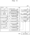
- the control device 50 includes a remaining battery charge acquisition unit 51, a remaining battery charge determination unit 52, an occupant position detection unit 53, an annunciation unit 54, a charging sensing unit 55, a physical unlocking sensing unit 56, and an unlocking mechanism control unit 57.
- Each of the remaining battery charge acquisition unit 51, the remaining battery charge determination unit 52, the occupant position detection unit 53, the annunciation unit 54, the charging sensing unit 55, the physical unlocking sensing unit 56, and the unlocking mechanism control unit 57 indicates software in which functional features of the control device 50 are illustrated as blocks. Details of each function will be described later.
- the annunciation unit 54 is an example of "annunciation circuit" in the present disclosure
- the unlocking mechanism control unit 57 is an example of "unlocking mechanism control circuit" in the present disclosure.
- the charging sensing unit 55 senses that the auxiliary battery 12 is being charged.
- the physical unlocking sensing unit 56 senses that the physical unlocking mechanism 70 has unlocked the door 110 (130).
- the unlocking mechanism control unit 57 drives the electric unlocking mechanism 60.
- the electric unlocking mechanism 60 is a mechanism for unlocking each of the doors 110 and 130 of the vehicle 100 (releasing an electronic lock).
- the electric unlocking mechanism 60 electrically unlocks each of the doors 110 and 130 that are in a locked state.
- the physical unlocking mechanism 70 is a mechanism for unlocking each of the doors 110 and 130 of the vehicle 100 (releasing a mechanical lock).
- the physical unlocking mechanism 70 physically unlocks each of the doors 110 and 130 that are in a locked state.
- the communication device 80 includes various types of communication interfaces.
- the communication device 80 performs wireless communication with a communication device that is outside of the vehicle 100.
- the communication device 80 communicates with a user terminal 900 (smartphone, smart watch, personal computer (PC), or the like) that is owned by the user of the vehicle 100.
- the communication device 80 may be configured to be capable of accessing the Internet.
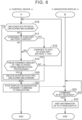
- FIG. 3 is a diagram showing sequence control (control method) by the control device 50 and the navigation display 31.
- the sequence shown in FIG. 3 may be periodically executed at predetermined time intervals (e.g., once every minute). Also, the sequence control in FIG. 3 may be executed only when the vehicle 100 is stopped.
- step S10 the control device 50 (remaining battery charge acquisition unit 51) acquires information regarding remaining SOC of the auxiliary battery 12.
- step S11 the control device 50 (remaining battery charge determination unit 52) determines whether the remaining SOC of the auxiliary battery 12 of which the information was acquired in step S10 is below 10%.
- the threshold value of 10% is a value set in advance in the control device 50.
- step S12 the control device 50 determines whether the outside temperature is higher than 30°C.
- the control device 50 performs the determination in step S12 based on the detected value of the outside temperature sensor 40 (see FIG. 2 ).
- the processing advances to step S13.
- the outside temperature is no higher than 30°C (No in S12)
- the processing ends.
- step S13 the control device 50 (occupant position detection unit 53) determines whether a user is riding in vehicle 100.
- the control device 50 occupant position detection unit 53
- step S14 the processing advances to step S14.
- no user is riding in the vehicle 100 (No in S13)
- step S14 the control device 50 (occupant position detection unit 53) determines the door that is closest to the occupant. For example, when the user is only in the driver's seat, the control device 50 (occupant position detection unit 53) determines the door 110 to be the door closest to the occupant. In this case, the door 110 is an example of "proximity door” in the present disclosure. Also, when the user is only in the rear seat, the control device 50 (occupant position detection unit 53) determines the door 130 to be the door closest to the occupant. In this case, the door 130 is an example of "proximity door” in the present disclosure.
- step S15 the control device 50 (annunciation unit 54) displays a position of the physical unlocking mechanism 70 corresponding to the door 110 closest to the occupant, and how to unlock the door 110 by the physical unlocking mechanism 70, on the navigation display 31. Specifically, the control device 50 (annunciation unit 54) performs processing of transmitting a command (control signal) to the navigation display 31 to display the above information (hereinafter sometimes referred to as annunciation processing). The processing then advances to step A. The description of step A and thereafter will be described later with reference to FIG. 6 .
- step S30 the navigation display 31 determines whether the command (control signal) in step S15 has been received.
- the processing advances to step S31.
- no command (control signal) in S15 No in S30, the processing ends.
- FIG. 5 illustrates, as a modification of FIG. 4 , a screen displayed on the navigation display 31 when the door 130 is determined to be the door closest to the occupant.
- the door inner-side portion 140 corresponding to the door 130 is displayed on the navigation display 31 illustrated in FIG. 5 .
- the door inner-side portion 140 is provided with an armrest 141 on which various types of switches are disposed, a window button 142, a pocket 143, and a door open/close button 62.
- the window button 142 and the door open/close button 62 are disposed on the armrest 141.
- the door open/close button 62 is a mechanism included in the electric unlocking mechanism 60.
- Pressing the door open/close button 62 controls the electric unlocking mechanism 60 and the door 130 is electrically unlocked.
- the screen illustrated in FIG. 5 indicates steps of how to unlock the door 130 using the physical unlocking mechanism 70.
- the screen illustrated in FIG. 5 indicates the steps of how to manually unlock for the door 130, using sets of numbers (1 to 3) and arrows.
- a first step is a step of removing a mat 72 from a bottom of the pocket 143, as indicated by a mark 31c displaying the number "1", and an arrow 31d.
- a second step is a step of removing an access door 73 provided below the mat 72, as indicated by a mark 31e displaying the number "2", and an arrow 31f.
- a third step is a step of pulling on a cable 74 provided below the access door 73, as indicated by a mark 31g displaying the number "3", and an arrow 31h. Note that the second step and the third step are displayed on an enlarged screen 31i. Also, each of the mat 72, the access door 73, and the cable 74 is a mechanism included in the physical unlocking mechanism 70.
- FIG. 6 is a sequence diagram showing a continuation of the sequence control in FIG. 3 .
- the control device 50 determines whether the door 110 has been unlocked by the physical unlocking mechanism 70. That is to say, the control device 50 (physical unlocking sensing unit 56) determines whether the door 110 has been unlocked by the physical unlocking mechanism 70 while the position of the physical unlocking mechanism 70 corresponding to the door 110 and how to unlock the door 110 by the physical unlocking mechanism 70 are displayed on the navigation display 31.
- the processing advances to step S21.
- the processing advances to step S17.
- step S17 the control device 50 (charging sensing unit 55) determines whether charging of the auxiliary battery 12 has started. That is to say, the control device 50 (physical unlocking sensing unit 56) determines whether charging of the auxiliary battery 12 has started while the position of the physical unlocking mechanism 70 corresponding to the door 110 and how to unlock the door 110 by the physical unlocking mechanism 70 are displayed on the navigation display 31.
- the control device 50 (charging sensing unit 55) may determine that charging of the auxiliary battery 12 has started (charging is being executed) upon detecting that the SOC of the auxiliary battery 12 has increased in a state in which a charging plug (omitted from illustration) is connected to an inlet (omitted from illustration) of the vehicle 100.
- step S18 When charging of the auxiliary battery 12 has started (Yes in S17), the processing advances to step S18.
- the processing advances to step S19.
- step S18 the control device 50 (remaining battery charge determination unit 52) determines whether the auxiliary battery 12 has been charged until the SOC thereof is no lower than 10%.
- the processing advances to step S21.
- the processing advances to step S19.
- step S19 the control device 50 determines whether a predetermined amount of time (e.g., 10 minutes) has elapsed since the position of the physical unlocking mechanism 70 corresponding to the door 110 and how to unlock the door 110 by the physical unlocking mechanism 70 was displayed on the navigation display 31 (the above annunciation processing was executed). That is to say, the control device 50 determines whether the door 110 has not been unlocked by the physical unlocking mechanism 70 within a predetermined amount of time following the above annunciation processing being executed.
- the processing advances to step S20.
- the predetermined amount of time has not elapsed (No in S19)
- the processing returns to step S16.
- step S20 the control device 50 (unlocking mechanism control unit 57) controls the electric unlocking mechanism 60 to electrically unlock the door 110.
- the control device 50 (unlocking mechanism control unit 57) transmits, to the electric unlocking mechanism 60, a command (control signal) to drive the electric unlocking mechanism 60 (to cause the electric unlocking mechanism 60 to unlock the door 110).
- the door 110 may be left in an ajar state, for example, or may be completely unlocked.
- step S33 the navigation display 31 hides from display the information from step S15 (the position of the physical unlocking mechanism 70 corresponding to the door 110, and how to unlock the door 110 by the physical unlocking mechanism 70).
- sequence shown in FIG. 6 is an example, and the present disclosure is not limited to the example shown in FIG. 6 .
- execution one or more of the determination processing in steps S16 to S19 in FIG. 6 may be omitted.
- execution all of the determination processing in steps S16 to S19 may be omitted.
- annunciation is performed to the user regarding both the position of the physical unlocking mechanism and how to unlock, using the physical unlocking mechanism, but the present disclosure is not limited thereto. Annunciation may be performed to the user of just one of the position of the physical unlocking mechanism and how to unlock using the physical unlocking mechanism.
- annunciation of information regarding the physical unlocking mechanism is performed when the SOC of the auxiliary battery 12 falls below 10%, but the present disclosure is not limited thereto.
- the above annunciation processing may be executed when the remaining electric power amount of the auxiliary battery 12 (1) reaches an electric power amount that is minimally required to execute the annunciation processing, (2) falls below an electric power amount that is minimally required to perform electrical unlocking of the door, (3) falls below an electric power amount at which electrically unlocking the door is not possible but the annunciation processing can be performed, or falls below an electric power amount obtained by adding a predetermined amount to the electric power amounts of (1) and (2).
- each of the control device 50 and the electric unlocking mechanism 60 is supplied with electric power from the auxiliary battery 12, but the present disclosure is not limited thereto. At least one of the control device 50 and the electric unlocking mechanism 60 may be supplied with electric power from the drive battery 11.
- the present disclosure is not limited thereto.
- the above information may be displayed on a rear seat display.
- the screen of the navigation display 31 may be divided into two.
- Information regarding the physical unlocking mechanism 70 corresponding to a driver's door may be displayed on one half of the divided screen, and also information regarding the physical unlocking mechanism 70 corresponding to a passenger door may be displayed on the other half of the divided screen.
- the door it is also conceivable for the door to be unlocked by an electric unlocking mechanism in accordance with the amount of charge of a battery (e.g., an auxiliary battery) becoming smaller than a predetermined threshold value.
- a battery e.g., an auxiliary battery
- the door is unlocked (in an ajar state or in a completely unlocked state) by the electric unlocking mechanism without executing the annunciation processing of the embodiment described above.
- annunciation processing is executed when the user is riding in the vehicle 100, and also the amount of charge of the auxiliary battery 12 becomes smaller than a predetermined threshold value, but the present disclosure is not limited thereto.
- the annunciation processing may be executed even when the user is not riding in the vehicle 100.
- the present disclosure is not limited thereto.
- a weight sensor or a human-presence sensor provided in the vehicle may be used.
- an example is described in which an image indicating the position of the physical unlocking mechanism 70, or the like, is displayed on the navigation display 31 when the amount of charge of the auxiliary battery 12 becomes smaller than the predetermined threshold value, but the present disclosure is not limited thereto.
- a pop-up display 31j illustrated in FIG. 7 may be displayed on the navigation display 31 or the like.
- the pop-up display 31j includes a button 31k labeled "Learn more" along with a message, "Notification about manually unlocking door".
- explanatory text describing the position of the physical unlocking mechanism 70 and how to unlock using the physical unlocking mechanism 70, or the images and so forth in FIGS. 4 and 5 are displayed on the navigation display 31 or the like. Note that when the button 31k is not selected within a predetermined period of time (e.g., one minute) following the button 31k being displayed, the above explanatory text and images such as in FIGS. 4 and 5 may be automatically displayed on the navigation display 31, or the like.
- a predetermined period of time e.g., one minute
- the door inner-side portion 220 is provided with an armrest 221, a pocket 223, and a door open/close button 161 (electric unlocking mechanism 160).
- the door open/close button 161 is disposed on the armrest 221.
- a lever 171 is disposed in the pocket 223. Note that the door open/close button 161 and the lever 171 are included in the electric unlocking mechanism 160 and a physical unlocking mechanism 170, respectively.
- an enlarged screen 131a illustrating details of how to operate the lever 171 is displayed.
- An arrow 131b indicating how to operate the lever 171, is displayed on the enlarged screen 131a.
- FIG. 9 is a diagram illustrating a second modification of the image in FIG. 4 .
- a door inner-side portion 320 of a vehicle 300 is displayed on a navigation display 231.
- the door inner-side portion 320 is provided with an armrest 321, a window button 322, and a door unlocking lever 323.
- the armrest 321 is provided with the window button 322 and the door unlocking lever 323.
- the door unlocking lever 323 is included in each of the electric unlocking mechanism and the physical unlocking mechanism (signs omitted for both). Specifically, when the door unlocking lever 323 is pulled once, the electric unlocking mechanism is controlled and the door 310 is unlocked. Also, when the door unlocking lever 323 is pulled twice, the door 310 is unlocked by the physical unlocking mechanism.
- the screen illustrated in FIG. 9 displays an arrow 231a and an explanatory message 231b for describing how to physically unlock using the door unlocking lever 323. Note that the explanatory message 231b states "Pull twice".
- annunciation processing is executed by displaying information regarding the physical unlocking mechanism 70 on the navigation display 31 of the vehicle 100, but the present disclosure is not limited thereto.
- Information regarding the physical unlocking mechanism 70 may be displayed on the meter display 32, or alternately, annunciation of information regarding the physical unlocking mechanism 70 may be performed by audio from the speaker 33.
- FIG. 10 is a diagram showing a modification in which the command (control signal) in step S15 in the above embodiment is transmitted to the user terminal 900.
- a control device 150 transmission unit 151) (see FIG. 11 ) of a vehicle 400 controls the communication device 80 so as to transmit information regarding the position of the physical unlocking mechanism 70 corresponding to the door 110 and how to unlock the door 110 by the physical unlocking mechanism 70, to the user terminal 900.
- the user terminal 900 that has received the command (control signal) executes processing of steps S40 to S41, which are similar to steps S30 to S31 (see FIG. 3 ).
- a central processing unit (CPU) or the like which is omitted from illustration and is provided in the user terminal 900, is an example of "control device” in the present disclosure.
- the user terminal 900 is an example of “external device” in the present disclosure.
- the transmission unit 151 is an example of "transmission circuit” in the present disclosure.
- FIG. 12 is a diagram illustrating a URL 910 of a Web page, containing information regarding the physical unlocking mechanism 70, displayed on the user terminal 900.
- control executed by the control device 50 of the embodiment described above may be executed in the user terminal 900 or the external server.
- the SOC information of the auxiliary battery 12 may be acquired in the vehicle, and also the user terminal 900 or the external server that has received the SOC information from the vehicle may execute the annunciation processing.
Landscapes
- Engineering & Computer Science (AREA)
- Mechanical Engineering (AREA)
- Transportation (AREA)
- Power Engineering (AREA)
- Chemical & Material Sciences (AREA)
- Automation & Control Theory (AREA)
- Combustion & Propulsion (AREA)
- Human Computer Interaction (AREA)
- Life Sciences & Earth Sciences (AREA)
- Sustainable Development (AREA)
- Sustainable Energy (AREA)
- Lock And Its Accessories (AREA)
- Electric Propulsion And Braking For Vehicles (AREA)
Abstract
Description
- The present disclosure relates to a control device for a vehicle and a control method therefor.
-
Japanese Patent No. 06689907 - Here, although not explicitly described in the above-mentioned
Japanese Patent No. 06689907 - The present disclosure has been made to solve the above problems, and an object thereof is to provide a control device and a control method that can suppress situations from occurring in which a user is unable to exit a vehicle equipped with an electrically-unlocked door.
- A first aspect of the present disclosure is a control device of a vehicle. The vehicle includes a door, an electric unlocking mechanism that is supplied with electric power from a battery installed in the vehicle and that also electrically unlocks the door, and a physical unlocking mechanism for manually unlocking the door. The control device includes an annunciation circuit for performing annunciation of predetermined information to a user of the vehicle. The annunciation circuit is configured to, when an amount of charge of the battery is smaller than a predetermined threshold value, perform annunciation to the user of at least one piece of information of a position of the physical unlocking mechanism, and how to unlock the door by the physical unlocking mechanism.
- As described above, when the amount of charge of the battery becomes smaller than the predetermined threshold value, the control device performs annunciation to the user regarding at least one piece of information of the position of the physical unlocking mechanism, and how to unlock the door using the physical unlocking mechanism. Thus, even when unlocking by the electric unlocking mechanism cannot be performed due to insufficient amount of charge of the battery, the user can still perform unlocking by using the physical unlocking mechanism, based on the information that is announced by the annunciation unit. As a result, situations in which the user is not able to exit a vehicle equipped with an electrically unlocked door can be suppressed.
- In the control device, the annunciation circuit may cause a display device to display the at least one piece of information when the amount of charge is smaller than the predetermined threshold value. According to this configuration, the user can easily unlock the door using the physical unlocking mechanism, based on the information displayed on the display device.
- In the control device, wherein the display device may include at least one of a display installed in the vehicle and a user terminal not installed in the vehicle. According to this configuration, the user can operate the physical unlocking mechanism of the vehicle by viewing the information displayed on the display of the vehicle, and accordingly the user can operate the physical unlocking mechanism more easily than when performing operations of the physical unlocking mechanism by viewing a mobile device held in hand. Also, displaying at least one of the pieces of information on the user terminal enables the at least one piece of information to be displayed, regardless of the amount of charge of the battery of the vehicle.
- The door may include a proximity door located closest to the user riding in the vehicle. In the control device, the annunciation circuit may be configured to, when the amount of charge is smaller than the predetermined threshold value, perform annunciation of at least one piece of information of a position of the physical unlocking mechanism corresponding to the proximity door, and how to unlock the proximity door by the physical unlocking mechanism, to the user. According to this configuration, information regarding the physical unlocking mechanism of the proximity door closest to the user can be announced to the user. As a result, the physical unlocking mechanism can be made to be easier for the user to operate.
- In the control device, the annunciation circuit may be configured to end annunciation of the at least one piece of information to the user when the door is unlocked by the physical unlocking mechanism while annunciation of the at least one piece of information is being performed to the user. According to this configuration, wasteful consumption of electric power following the door being unlocked by the physical unlocking mechanism can be suppressed. Accordingly, for example, electric power and so forth can be reserved for communicating to the outside through a communication device or the like, that the amount of charge in the battery is low.
- In the control device, the annunciation circuit may be configured to end annunciation of the at least one piece of information to the user when charging of the battery is started while annunciation of the at least one piece of information is being performed to the user. According to this configuration, while the battery is being charged, consumption of electric power due to the annunciation of the information can be suppressed.
- The control device may further include an unlocking mechanism control circuit configured to drive the electric unlocking mechanism. The unlocking mechanism control circuit may be configured to unlock the door by the electric unlocking mechanism when the door is not unlocked by the physical unlocking mechanism within a predetermined amount of time following annunciation of the at least one piece of information being performed to the user. According to this configuration, situations in which the user is trapped in the vehicle, when the user is unable to operate the physical unlocking mechanism or the like, for example, can be suppressed.
- In the control device, the annunciation circuit may be configured to perform annunciation of the at least one piece of information to the user when the user is riding in the vehicle and also when the amount of charge is smaller than the predetermined threshold value. According to this configuration, situations in which annunciation of the at least one piece of information is performed to a user who is not riding in the vehicle can be suppressed.
- In the control device, the annunciation circuit may be configured to perform annunciation of the at least one piece of information to the user when an outside temperature is higher than a predetermined temperature and also the amount of charge is smaller than the predetermined threshold value. According to this configuration, situations in which the user is trapped in the vehicle inside which the temperature is high due to the high outside temperature can be suppressed.
- A second aspect of the present disclosure is a control device of a vehicle. The vehicle includes a door, an electric unlocking mechanism that is supplied with electric power from a battery installed in the vehicle and that also electrically unlocks the door, and a physical unlocking mechanism for manually unlocking the door. The control device may include a transmission circuit for transmitting information of the vehicle to an external device that is outside of the vehicle. The transmission circuit is configured to, when an amount of charge of the battery is smaller than a predetermined threshold value, transmit, to the external device, at least one piece of information of a position of the physical unlocking mechanism, and how to unlock the door by the physical unlocking mechanism.
- As described above, when the amount of charge of the battery becomes smaller than the predetermined threshold value, the control device transmits, to the external device, at least one piece of information of the position of the physical unlocking mechanism, and how to unlock the door using the physical unlocking mechanism. Thus, the user can obtain the at least one piece of information through the external device, and accordingly can unlock the door using the physical unlocking mechanism. As a result, situations in which the user is not able to exit a vehicle equipped with an electrically unlocked door can be suppressed.
- A third aspect of the present disclosure is a control method of a vehicle. The vehicle includes a door, an electric unlocking mechanism that is supplied with electric power from a battery installed in the vehicle and that also electrically unlocks the door, a physical unlocking mechanism for manually unlocking the door, and a control device. The control method includes, as an annunciation process, the control device performing annunciation of predetermined information to a user of the vehicle. The annunciation process includes a process of performing annunciation to the user of at least one piece of information of a position of the physical unlocking mechanism, and how to unlock the door by the physical unlocking mechanism, when an amount of charge of the battery is smaller than a predetermined threshold value.
- According to the above control method, as described above, when the amount of charge becomes smaller than the predetermined threshold value, annunciation is performed to the user regarding at least one piece of information of the position of the physical unlocking mechanism, and how to unlock the door using the physical unlocking mechanism. Thus, a control method that can suppress situations in which a user is unable to exit a vehicle equipped with an electrically unlocked door can be provided.
- In the control method, the annunciation process may include a process of the control device causing a display device to display the at least one piece of information when the amount of charge is smaller than the predetermined threshold value. According to this configuration, a control method can be provided in which the user can easily unlock the door using the physical unlocking mechanism, based on the information displayed on the display device.
- In the control method, the annunciation process may include a process of the control device causing the display device, including at least one of a display installed in the vehicle and a user terminal not installed in the vehicle, to display the at least one piece of information, when the amount of charge is smaller than the predetermined threshold value. With this configuration, a control method can be provided in which the user can operate the physical unlocking mechanism more easily than when performing operations of the physical unlocking mechanism by viewing a mobile device or the like that is held in hand. Also, displaying at least one of the pieces of information on the user terminal enables a control method to be provided in which the at least one piece of information can be displayed, regardless of the amount of charge of the battery of the vehicle.
- The door may include a proximity door located closest to the user riding in the vehicle. In the control method, the annunciation process may include a process of the control device performing annunciation to the user of at least one piece of information of a position of the physical unlocking mechanism corresponding to the proximity door, and how to unlock the proximity door by the physical unlocking mechanism, when the amount of charge is smaller than the predetermined threshold value. According to this configuration, a control method can be provided in which the user can more easily operate the physical unlocking mechanism.
- The control method may further include the control device ending annunciation of the at least one piece of information to the user, when the door is unlocked by the physical unlocking mechanism while annunciation of the at least one piece of information is being performed to the user. According to this configuration, a control method can be provided that can reserve electric power or the like for communicating to the outside through a communication device or the like that the amount of charge of the battery is low, for example.
- The control method may further include the control device ending annunciation of the at least one piece of information to the user, when charging of the battery is started while annunciation of the at least one piece of information is being performed to the user. According to this configuration, while the battery is being charged, consumption of electric power due to the annunciation of the information can be suppressed.
- The control method may further include the control device unlocking the door by the electric unlocking mechanism, when the door is not unlocked by the physical unlocking mechanism within a predetermined amount of time following annunciation of the at least one piece of information being performed to the user. According to this configuration, a control method can be provided that can suppress situations in which the user is trapped in the vehicle, when the user is unable to operate the physical unlocking mechanism or the like, for example.
- In the control method, the annunciation process may include a process of the control device performing annunciation of the at least one piece of information to the user when the user is riding in the vehicle and also the amount of charge is smaller than the predetermined threshold value. According to this configuration, a control method can be provided that can suppress situations in which annunciation of the at least one piece of information is performed to a user who is not riding in the vehicle.
- In the control method, the annunciation process may include a process of the control device performing annunciation to the user of the at least one piece of information when an outside temperature is higher than a predetermined temperature and also the amount of charge is smaller than the predetermined threshold value. According to this configuration, a control method can be provided that can suppress situations in which the user is trapped in the vehicle inside which the temperature is high due to the high outside temperature.
- In the control method, the annunciation process may include a process of the control device transmitting the at least one piece of information to an external device that is outside of the vehicle when the amount of charge is smaller than the predetermined threshold value. According to this configuration, a control method can be provided that enables the user to obtain the at least one piece of information with the external device.
- According to the present disclosure, situations in which a user is unable to exit a vehicle provided with a door that is electrically unlocked can be suppressed.
- Features, advantages, and technical and industrial significance of exemplary embodiments of the invention will be described below with reference to the accompanying drawings, in which like signs denote like elements, and wherein:
-
FIG. 1 is a diagram illustrating a configuration of a vehicle according to an embodiment; -
FIG. 2 is a block diagram illustrating a detailed configuration of the vehicle according to the embodiment; -
FIG. 3 is a sequence diagram showing control by a control device and a navigation display according to the embodiment; -
FIG. 4 is a first diagram illustrating a navigation display displaying information regarding a physical unlocking mechanism according to the embodiment; -
FIG. 5 is a second diagram illustrating the navigation display displaying information regarding the physical unlocking mechanism according to the embodiment; -
FIG. 6 is a sequence diagram showing a continuation of sequence control inFIG. 3 ; -
FIG. 7 is a diagram illustrating a pop-up display displayed on the navigation display according to a modification of the embodiment; -
FIG. 8 is a diagram illustrating a first modification ofFIG. 4 ; -
FIG. 9 is a diagram illustrating a second modification ofFIG. 4 ; -
FIG. 10 is a diagram showing a modification of the sequence diagram ofFIG. 3 ; -
FIG. 11 is a block diagram illustrating a detailed configuration of a vehicle according to a modification of the embodiment; and -
FIG. 12 is a diagram illustrating a Uniform Resource Locator (URL) of a Web page containing information regarding a physical unlocking mechanism being displayed on a user terminal. - An embodiment of the present disclosure will be described in detail below with reference to the drawings. The same or corresponding parts are denoted by the same signs throughout the drawings, and description thereof will not be repeated.
-
FIG. 1 is a side view of avehicle 100 in which a control device 50 (seeFIG. 2 ) according to the present embodiment is installed. Thevehicle 100 includes adoor 110 for a front seat and adoor 130 for a rear seat. Thevehicle 100 also includes anavigation display 31. Note that thenavigation display 31 is an example of a "display device" and a "display" in the present disclosure. - A door inner-
side portion 120 on which various types of switches and so forth are installed is disposed on a face of thedoor 110, on a vehicle cabin side thereof. A door inner-side portion 140 on which various types of switches and so forth are installed is disposed on a face of thedoor 130, on the vehicle cabin side thereof. Details of each of the door inner-side portion 120 and the door inner-side portion 140 will be described later. -
FIG. 2 is a block diagram illustrating a detailed configuration of thevehicle 100. In the example illustrated inFIG. 2 , thevehicle 100 is an electrified vehicle such as a battery electric vehicle (BEV), a plug-in hybrid electric vehicle (PHEV), or the like. Thevehicle 100 includes apower storage device 10, an in-vehicle camera 20, a human-machine interface (HMI)device 30, anoutside temperature sensor 40, thecontrol device 50, an electric unlockingmechanism 60, a physical unlockingmechanism 70, and acommunication device 80. The electric unlockingmechanism 60 and the physical unlockingmechanism 70 each include an unlocking mechanism for thedoor 110 and thedoor 130, respectively. - The
power storage device 10 includes adrive battery 11 and anauxiliary battery 12. Thedrive battery 11 stores electric power used for thevehicle 100 to travel and so forth (electric motor and so forth). Theauxiliary battery 12 supplies electric power to various types of functional equipment provided in the vehicle, such as a power source for a system, an electronic control unit (ECU), thenavigation display 31, and so forth. Note that theauxiliary battery 12 is an example of "battery" in the present disclosure. - When an electric power amount in the
auxiliary battery 12 becomes low, electric power is transferred from thedrive battery 11 to theauxiliary battery 12. For example, when a state of charge (SOC) of theauxiliary battery 12 falls below 15%, the above transfer is performed. - The in-
vehicle camera 20 acquires images of the interior of thevehicle 100. Just one in-vehicle camera 20 may be provided in thevehicle 100, or a plurality of the in-vehicle cameras 20 may be provided in thevehicle 100. - The
HMIdevice 30 includes thenavigation display 31, ameter display 32, aspeaker 33, and so forth. Theoutside temperature sensor 40 detects the outside temperature. - The
control device 50 includes a remaining batterycharge acquisition unit 51, a remaining batterycharge determination unit 52, an occupantposition detection unit 53, anannunciation unit 54, a chargingsensing unit 55, a physical unlockingsensing unit 56, and an unlockingmechanism control unit 57. Each of the remaining batterycharge acquisition unit 51, the remaining batterycharge determination unit 52, the occupantposition detection unit 53, theannunciation unit 54, the chargingsensing unit 55, the physical unlockingsensing unit 56, and the unlockingmechanism control unit 57 indicates software in which functional features of thecontrol device 50 are illustrated as blocks. Details of each function will be described later. Theannunciation unit 54 is an example of "annunciation circuit" in the present disclosure, and the unlockingmechanism control unit 57 is an example of "unlocking mechanism control circuit" in the present disclosure. - The remaining battery
charge acquisition unit 51 acquires information regarding the state of charge (SOC) of theauxiliary battery 12. The remaining batterycharge determination unit 52 determines whether the state of charge (SOC) of theauxiliary battery 12 is below a predetermined value. The occupantposition detection unit 53 detects that a user is riding in thevehicle 100, and detects a position of the user riding in thevehicle 100. Theannunciation unit 54 notifies the user of thevehicle 100 of predetermined information. - The charging
sensing unit 55 senses that theauxiliary battery 12 is being charged. The physical unlockingsensing unit 56 senses that the physical unlockingmechanism 70 has unlocked the door 110 (130). The unlockingmechanism control unit 57 drives the electric unlockingmechanism 60. - The electric unlocking
mechanism 60 is a mechanism for unlocking each of thedoors mechanism 60 electrically unlocks each of thedoors - The physical unlocking
mechanism 70 is a mechanism for unlocking each of thedoors mechanism 70 physically unlocks each of thedoors - The
communication device 80 includes various types of communication interfaces. Thecommunication device 80 performs wireless communication with a communication device that is outside of thevehicle 100. For example, thecommunication device 80 communicates with a user terminal 900 (smartphone, smart watch, personal computer (PC), or the like) that is owned by the user of thevehicle 100. Also, thecommunication device 80 may be configured to be capable of accessing the Internet. -
FIG. 3 is a diagram showing sequence control (control method) by thecontrol device 50 and thenavigation display 31. The sequence shown inFIG. 3 may be periodically executed at predetermined time intervals (e.g., once every minute). Also, the sequence control inFIG. 3 may be executed only when thevehicle 100 is stopped. - In step S10, the control device 50 (remaining battery charge acquisition unit 51) acquires information regarding remaining SOC of the
auxiliary battery 12. - In step S11, the control device 50 (remaining battery charge determination unit 52) determines whether the remaining SOC of the
auxiliary battery 12 of which the information was acquired in step S10 is below 10%. The threshold value of 10% is a value set in advance in thecontrol device 50. When the SOC of theauxiliary battery 12 is below 10% (Yes in S11), the processing advances to step S12. When the SOC of theauxiliary battery 12 is no lower than 10% (No in S11), the processing ends. - In step S12, the
control device 50 determines whether the outside temperature is higher than 30°C. Thecontrol device 50 performs the determination in step S12 based on the detected value of the outside temperature sensor 40 (seeFIG. 2 ). When the outside temperature is higher than 30°C (Yes in S12), the processing advances to step S13. When the outside temperature is no higher than 30°C (No in S12), the processing ends. - In step S13, the control device 50 (occupant position detection unit 53) determines whether a user is riding in
vehicle 100. The control device 50 (occupant position detection unit 53) performs the determination in step S13 based on an image captured by the in-vehicle camera 20. When the user is riding in the vehicle 100 (Yes in S13), the processing advances to step S14. When no user is riding in the vehicle 100 (No in S13), the processing ends. - In step S14, the control device 50 (occupant position detection unit 53) determines the door that is closest to the occupant. For example, when the user is only in the driver's seat, the control device 50 (occupant position detection unit 53) determines the
door 110 to be the door closest to the occupant. In this case, thedoor 110 is an example of "proximity door" in the present disclosure. Also, when the user is only in the rear seat, the control device 50 (occupant position detection unit 53) determines thedoor 130 to be the door closest to the occupant. In this case, thedoor 130 is an example of "proximity door" in the present disclosure. Also, when there are users in each of the driver's seat and the rear seat, the control device 50 (occupant position detection unit 53) determines each of thedoor 110 and thedoor 130 to be the door closest to the occupant. In this case, each of thedoor 110 and thedoor 130 is an example of "proximity door" in the present disclosure. In the following, thedoor 110 is assumed to be the door closest to the occupant. - In step S15, the control device 50 (annunciation unit 54) displays a position of the physical unlocking
mechanism 70 corresponding to thedoor 110 closest to the occupant, and how to unlock thedoor 110 by the physical unlockingmechanism 70, on thenavigation display 31. Specifically, the control device 50 (annunciation unit 54) performs processing of transmitting a command (control signal) to thenavigation display 31 to display the above information (hereinafter sometimes referred to as annunciation processing). The processing then advances to step A. The description of step A and thereafter will be described later with reference toFIG. 6 . - In step S30, the
navigation display 31 determines whether the command (control signal) in step S15 has been received. When the command (control signal) in S15 has been received (Yes in S30), the processing advances to step S31. When no command (control signal) in S15 has been received (No in S30), the processing ends. - In step S31, the
navigation display 31 displays the information from step S15 (the position of the physical unlockingmechanism 70 corresponding to thedoor 110, and how to unlock thedoor 110 by the physical unlocking mechanism 70). The processing then advances to step B. The description of step B and thereafter will be described later with reference toFIG. 6 . -
FIG. 4 illustrates an example of a screen displayed on thenavigation display 31 in step S31. The door inner-side portion 120 corresponding to thedoor 110 is displayed on thenavigation display 31 illustrated inFIG. 4 . - The door inner-
side portion 120 is provided with anarmrest 121 on which various types of switches are disposed, a plurality ofwindow buttons 122, alever 71, and a door open/close button 61. Thewindow buttons 122, thelever 71, and the door open/close button 61 are disposed on thearmrest 121. Note that the door open/close button 61 and thelever 71 are included in the electric unlockingmechanism 60 and the physical unlockingmechanism 70, respectively. - Operating one of the
window buttons 122 opens (or closes) a window corresponding to thewindow button 122 that is operated. - Pressing the door open/
close button 61 controls the electric unlockingmechanism 60 and thedoor 110 is electrically unlocked. - By pulling up the
lever 71, thedoor 110 is physically unlocked by the physical unlockingmechanism 70. Note that thelever 71 is adjacent to thewindow buttons 122 and also is disposed at a position spaced apart from the door open/close button 61. - In the screen illustrated in
FIG. 4 , anenlarged screen 31a, demonstrating details of how to operate thelever 71, is displayed. Anarrow 31b, indicating how to operate thelever 71, is displayed on theenlarged screen 31a. Note that the image displayed on thenavigation display 31 may be a still image or a moving image. -
FIG. 5 illustrates, as a modification ofFIG. 4 , a screen displayed on thenavigation display 31 when thedoor 130 is determined to be the door closest to the occupant. The door inner-side portion 140 corresponding to thedoor 130 is displayed on thenavigation display 31 illustrated inFIG. 5 . - The door inner-
side portion 140 is provided with anarmrest 141 on which various types of switches are disposed, awindow button 142, apocket 143, and a door open/close button 62. Thewindow button 142 and the door open/close button 62 are disposed on thearmrest 141. Note that the door open/close button 62 is a mechanism included in the electric unlockingmechanism 60. - Operating the
window button 142 opens (or closes) a window of thedoor 130. - Pressing the door open/
close button 62 controls the electric unlockingmechanism 60 and thedoor 130 is electrically unlocked. - The screen illustrated in
FIG. 5 indicates steps of how to unlock thedoor 130 using the physical unlockingmechanism 70. The screen illustrated inFIG. 5 indicates the steps of how to manually unlock for thedoor 130, using sets of numbers (1 to 3) and arrows. First, a first step is a step of removing amat 72 from a bottom of thepocket 143, as indicated by amark 31c displaying the number "1", and anarrow 31d. A second step is a step of removing anaccess door 73 provided below themat 72, as indicated by amark 31e displaying the number "2", and anarrow 31f. A third step is a step of pulling on acable 74 provided below theaccess door 73, as indicated by amark 31g displaying the number "3", and anarrow 31h. Note that the second step and the third step are displayed on anenlarged screen 31i. Also, each of themat 72, theaccess door 73, and thecable 74 is a mechanism included in the physical unlockingmechanism 70. -
FIG. 6 is a sequence diagram showing a continuation of the sequence control inFIG. 3 . In step S16, the control device 50 (physical unlocking sensing unit 56) determines whether thedoor 110 has been unlocked by the physical unlockingmechanism 70. That is to say, the control device 50 (physical unlocking sensing unit 56) determines whether thedoor 110 has been unlocked by the physical unlockingmechanism 70 while the position of the physical unlockingmechanism 70 corresponding to thedoor 110 and how to unlock thedoor 110 by the physical unlockingmechanism 70 are displayed on thenavigation display 31. When the physical unlockingmechanism 70 has unlocked the door (Yes in S16), the processing advances to step S21. When the physical unlockingmechanism 70 has not unlocked the door (No in S16), the processing advances to step S17. - In step S17, the control device 50 (charging sensing unit 55) determines whether charging of the
auxiliary battery 12 has started. That is to say, the control device 50 (physical unlocking sensing unit 56) determines whether charging of theauxiliary battery 12 has started while the position of the physical unlockingmechanism 70 corresponding to thedoor 110 and how to unlock thedoor 110 by the physical unlockingmechanism 70 are displayed on thenavigation display 31. The control device 50 (charging sensing unit 55) may determine that charging of theauxiliary battery 12 has started (charging is being executed) upon detecting that the SOC of theauxiliary battery 12 has increased in a state in which a charging plug (omitted from illustration) is connected to an inlet (omitted from illustration) of thevehicle 100. When charging of theauxiliary battery 12 has started (Yes in S17), the processing advances to step S18. When charging of theauxiliary battery 12 has not started (No in S17), the processing advances to step S19. - In step S18, the control device 50 (remaining battery charge determination unit 52) determines whether the
auxiliary battery 12 has been charged until the SOC thereof is no lower than 10%. When the SOC of theauxiliary battery 12 is no lower than 10% (Yes in S18), the processing advances to step S21. When the SOC is below 10% (No in S18), the processing advances to step S19. - In step S19, the
control device 50 determines whether a predetermined amount of time (e.g., 10 minutes) has elapsed since the position of the physical unlockingmechanism 70 corresponding to thedoor 110 and how to unlock thedoor 110 by the physical unlockingmechanism 70 was displayed on the navigation display 31 (the above annunciation processing was executed). That is to say, thecontrol device 50 determines whether thedoor 110 has not been unlocked by the physical unlockingmechanism 70 within a predetermined amount of time following the above annunciation processing being executed. When the predetermined amount of time has elapsed (when thedoor 110 has not been unlocked by the physical unlockingmechanism 70 within the predetermined amount of time) (Yes in S19), the processing advances to step S20. When the predetermined amount of time has not elapsed (No in S19), the processing returns to step S16. - In step S20, the control device 50 (unlocking mechanism control unit 57) controls the electric unlocking
mechanism 60 to electrically unlock thedoor 110. At this time, the control device 50 (unlocking mechanism control unit 57) transmits, to the electric unlockingmechanism 60, a command (control signal) to drive the electric unlocking mechanism 60 (to cause the electric unlockingmechanism 60 to unlock the door 110). In this case, thedoor 110 may be left in an ajar state, for example, or may be completely unlocked. - In step S21, the control device 50 (annunciation unit 54) ends displaying of the position of the physical unlocking
mechanism 70 corresponding to thedoor 110, and how to unlock thedoor 110 by the physical unlockingmechanism 70, on thenavigation display 31. Specifically, the control device 50 (annunciation unit 54) transmits a command (control signal) to thenavigation display 31, to stop the display. - In step S32, the
navigation display 31 determines whether the command (control signal) in step S21 has been received. When the command (control signal) in S21 has been received (Yes in S32), the processing advances to step S33. When no command (control signal) in S21 has been received (No in S32), the processing of step S32 is repeated. - In step S33, the
navigation display 31 hides from display the information from step S15 (the position of the physical unlockingmechanism 70 corresponding to thedoor 110, and how to unlock thedoor 110 by the physical unlocking mechanism 70). - Note that the sequence shown in
FIG. 6 is an example, and the present disclosure is not limited to the example shown inFIG. 6 . For example, execution one or more of the determination processing in steps S16 to S19 inFIG. 6 may be omitted. For example, execution all of the determination processing in steps S16 to S19 may be omitted. - As described above, according to the present embodiment, when the amount of charge of the
auxiliary battery 12 falls below 10%, theannunciation unit 54 performs annunciation to the user regarding the position of the physical unlockingmechanism 70 corresponding to thedoor 110, and information regarding how to unlock thedoor 110 using the physical unlockingmechanism 70. Thus, information regarding the physical unlockingmechanism 70 can be notified to the user before the electric unlockingmechanism 60 stops operating due to insufficient amount of charge of theauxiliary battery 12. As a result, even when the electric unlockingmechanism 60 stops operating, the user can still unlock thedoor 110 using the physical unlockingmechanism 70. - In the embodiment described above, an example is described in which annunciation is performed to the user regarding both the position of the physical unlocking mechanism and how to unlock, using the physical unlocking mechanism, but the present disclosure is not limited thereto. Annunciation may be performed to the user of just one of the position of the physical unlocking mechanism and how to unlock using the physical unlocking mechanism.
- In the above embodiment, an example is described in which annunciation of information regarding the physical unlocking mechanism is performed when the SOC of the
auxiliary battery 12 falls below 10%, but the present disclosure is not limited thereto. The above annunciation processing may be executed when the remaining electric power amount of the auxiliary battery 12 (1) reaches an electric power amount that is minimally required to execute the annunciation processing, (2) falls below an electric power amount that is minimally required to perform electrical unlocking of the door, (3) falls below an electric power amount at which electrically unlocking the door is not possible but the annunciation processing can be performed, or falls below an electric power amount obtained by adding a predetermined amount to the electric power amounts of (1) and (2). - In the above embodiment, an example is described in which each of the
control device 50 and the electric unlockingmechanism 60 is supplied with electric power from theauxiliary battery 12, but the present disclosure is not limited thereto. At least one of thecontrol device 50 and the electric unlockingmechanism 60 may be supplied with electric power from thedrive battery 11. - Although the above embodiment describes an example in which information regarding the physical unlocking
mechanism 70 is displayed on thenavigation display 31, the present disclosure is not limited thereto. For example, when a user is riding in the rear seat, the above information may be displayed on a rear seat display. Also, when users are seated in each of the driver's seat and a passenger seat, the screen of thenavigation display 31 may be divided into two. Information regarding the physical unlockingmechanism 70 corresponding to a driver's door may be displayed on one half of the divided screen, and also information regarding the physical unlockingmechanism 70 corresponding to a passenger door may be displayed on the other half of the divided screen. - It is also conceivable for the door to be unlocked by an electric unlocking mechanism in accordance with the amount of charge of a battery (e.g., an auxiliary battery) becoming smaller than a predetermined threshold value. In this case, the door is unlocked (in an ajar state or in a completely unlocked state) by the electric unlocking mechanism without executing the annunciation processing of the embodiment described above.
- In the above embodiment, an example is described in which the annunciation processing is executed when the user is riding in the
vehicle 100, and also the amount of charge of theauxiliary battery 12 becomes smaller than a predetermined threshold value, but the present disclosure is not limited thereto. The annunciation processing may be executed even when the user is not riding in thevehicle 100. - In the above embodiment, an example is described in which the annunciation processing is executed when the outside temperature is higher than a predetermined temperature, and also the amount of charge of the
auxiliary battery 12 becomes smaller than the predetermined threshold value, but the present disclosure is not limited to this. The annunciation processing may be executed even when the outside temperature is below the predetermined temperature. - Although the above embodiment describes an example in which the annunciation processing is executed based on the detected value of the
outside temperature sensor 40 installed in thevehicle 100, the present disclosure is not limited thereto. The annunciation processing may be executed based on a detection value of a temperature sensor provided outside of the vehicle, temperature information on the Internet, or the like. - In the above embodiment, an example is described in which the number of occupants and the positions of the occupants in the
vehicle 100 are sensed based on images captured by the in-vehicle camera 20, but the present disclosure is not limited thereto. For example, a weight sensor or a human-presence sensor provided in the vehicle may be used. - In the above embodiment, an example has been set forth in which the annunciation processing is simply to display information regarding the physical unlocking mechanism on the
navigation display 31 or the like, but the present disclosure is not limited to this. For example, when the surroundings are dark, such as at night, in addition to displaying the above information, processing of illuminating the physical unlocking mechanism may be performed as annunciation processing. In this case, the threshold value of the state of charge (SOC) of the auxiliary battery 12 (10% in the above embodiment) may be increased by a predetermined amount (for example, 2%) to compensate for the amount of electric power used for illumination, or alternatively, a period of displaying the information on thenavigation display 31 may be shortened. - In the above embodiment, an example is described in which an image indicating the position of the physical unlocking
mechanism 70, or the like, is displayed on thenavigation display 31 when the amount of charge of theauxiliary battery 12 becomes smaller than the predetermined threshold value, but the present disclosure is not limited thereto. When the amount of charge of theauxiliary battery 12 becomes smaller than the predetermined threshold value, a pop-updisplay 31j illustrated inFIG. 7 may be displayed on thenavigation display 31 or the like. The pop-updisplay 31j includes abutton 31k labeled "Learn more" along with a message, "Notification about manually unlocking door". When thebutton 31k is selected, explanatory text describing the position of the physical unlockingmechanism 70 and how to unlock using the physical unlockingmechanism 70, or the images and so forth inFIGS. 4 and 5 , are displayed on thenavigation display 31 or the like. Note that when thebutton 31k is not selected within a predetermined period of time (e.g., one minute) following thebutton 31k being displayed, the above explanatory text and images such as inFIGS. 4 and 5 may be automatically displayed on thenavigation display 31, or the like. - In the above embodiment, an example is described in which starting of charging of the
auxiliary battery 12 is sensed when the SOC of theauxiliary battery 12 increases in a state in which the charging plug is connected, but the present disclosure is not limited thereto. For example, when the SOC of the battery installed in the vehicle increases due to replacement of the battery, charging of the battery may be sensed. - In the above embodiment, an example is described in which the annunciation processing is ended when the SOC of the
auxiliary battery 12 is charged to 10% or higher, following annunciation to the user, but the present disclosure is not limited to this. When the SOC of theauxiliary battery 12 increases even slightly due to charging (e.g., when the SOC increases by 1% or more) following annunciation to the user, the annunciation processing may be executed. -
FIG. 8 is a diagram illustrating a first modification ofFIG. 4 . In the example illustrated inFIG. 8 , a door inner-side portion 220 of avehicle 200 is displayed on anavigation display 131. - The door inner-
side portion 220 is provided with anarmrest 221, apocket 223, and a door open/close button 161 (electric unlocking mechanism 160). The door open/close button 161 is disposed on thearmrest 221. Alever 171 is disposed in thepocket 223. Note that the door open/close button 161 and thelever 171 are included in the electric unlockingmechanism 160 and a physical unlockingmechanism 170, respectively. - Pressing the door open/
close button 161 controls the electric unlockingmechanism 160 and thedoor 210 is electrically unlocked. Note that thedoor 210 in the unlocked state is opened by pressing the door open/close button 161 once. Also, thedoor 210 in the locked state is opened by pressing the door open/close button 161 twice. - When the lever 171 (physical unlocking mechanism 170) disposed in the
pocket 223 is pulled upward, thedoor 210 is physically unlocked by the physical unlockingmechanism 170. Note that thelever 171 is disposed at a position spaced away from the door open/close button 161. - In the screen illustrated in
FIG. 8 , anenlarged screen 131a, illustrating details of how to operate thelever 171, is displayed. Anarrow 131b, indicating how to operate thelever 171, is displayed on theenlarged screen 131a. -
FIG. 9 is a diagram illustrating a second modification of the image inFIG. 4 . In the example illustrated inFIG. 9 , a door inner-side portion 320 of avehicle 300 is displayed on anavigation display 231. - The door inner-
side portion 320 is provided with anarmrest 321, awindow button 322, and adoor unlocking lever 323. Thearmrest 321 is provided with thewindow button 322 and thedoor unlocking lever 323. - In the example illustrated in
FIG. 9 , thedoor unlocking lever 323 is included in each of the electric unlocking mechanism and the physical unlocking mechanism (signs omitted for both). Specifically, when thedoor unlocking lever 323 is pulled once, the electric unlocking mechanism is controlled and thedoor 310 is unlocked. Also, when thedoor unlocking lever 323 is pulled twice, thedoor 310 is unlocked by the physical unlocking mechanism. - The screen illustrated in
FIG. 9 displays anarrow 231a and anexplanatory message 231b for describing how to physically unlock using thedoor unlocking lever 323. Note that theexplanatory message 231b states "Pull twice". - In the above embodiment, an example is described in which the annunciation processing is executed by displaying information regarding the physical unlocking
mechanism 70 on thenavigation display 31 of thevehicle 100, but the present disclosure is not limited thereto. Information regarding the physical unlockingmechanism 70 may be displayed on themeter display 32, or alternately, annunciation of information regarding the physical unlockingmechanism 70 may be performed by audio from thespeaker 33. - Further, information regarding the physical unlocking mechanism 70 (images in
FIG. 4 and so forth) may be displayed on theuser terminal 900.FIG. 10 is a diagram showing a modification in which the command (control signal) in step S15 in the above embodiment is transmitted to theuser terminal 900. A control device 150 (transmission unit 151) (seeFIG. 11 ) of avehicle 400 controls thecommunication device 80 so as to transmit information regarding the position of the physical unlockingmechanism 70 corresponding to thedoor 110 and how to unlock thedoor 110 by the physical unlockingmechanism 70, to theuser terminal 900. Theuser terminal 900 that has received the command (control signal) executes processing of steps S40 to S41, which are similar to steps S30 to S31 (seeFIG. 3 ). Detailed description of steps S40 to S41 will be omitted. In this case, a central processing unit (CPU) or the like, which is omitted from illustration and is provided in theuser terminal 900, is an example of "control device" in the present disclosure. Also, theuser terminal 900 is an example of "external device" in the present disclosure. Also, thetransmission unit 151 is an example of "transmission circuit" in the present disclosure. - Note that
FIG. 12 is a diagram illustrating aURL 910 of a Web page, containing information regarding the physical unlockingmechanism 70, displayed on theuser terminal 900. - Also, although an example in which information regarding the physical unlocking
mechanism 70 is transmitted to theuser terminal 900 is set forth in the example inFIG. 10 , the present disclosure is not limited to this. Information regarding the physical unlockingmechanism 70 may be transmitted from the control device 150 (transmission unit 151) of thevehicle 400 to an external server that is omitted from illustration, via thecommunication device 80. A command (control signal) to display the information on the display screen of theuser terminal 900 may then be transmitted from the external server to theuser terminal 900. In this case, the external server is an example of "external device" in the present disclosure. - Also, at least part of the control executed by the
control device 50 of the embodiment described above may be executed in theuser terminal 900 or the external server. For example, the SOC information of theauxiliary battery 12 may be acquired in the vehicle, and also theuser terminal 900 or the external server that has received the SOC information from the vehicle may execute the annunciation processing. - Also, in the embodiment described above, an example is set forth in which the
vehicle 100 is an electrified vehicle such as a BEV, a PHEV, or the like, but the present disclosure is not limited thereto. For example, the vehicle may be a gasoline vehicle, as long as it is equipped with a battery. - The embodiments disclosed herein should be construed as exemplary in all respects and not restrictive. The scope of the present disclosure is set forth in the claims rather than in the above description of the embodiments, and is intended to include all modifications within the meaning and scope equivalent to those of the claims.
Claims (20)
- A control device (50) of a vehicle (100) that includes a door (110), an electric unlocking mechanism (60) that is supplied with electric power from a battery (12) installed in the vehicle (100) and that also electrically unlocks the door (110), and a physical unlocking mechanism (70) for manually unlocking the door (110), the control device (50) comprising: an annunciation circuit (54) for performing annunciation of predetermined information to a user of the vehicle (100), wherein
the annunciation circuit (54) is configured to, when an amount of charge of the battery (12) is smaller than a predetermined threshold value, perform annunciation to the user of at least one piece of information of a position of the physical unlocking mechanism (70), and how to unlock the door (110) by the physical unlocking mechanism (70). - The control device (50) according to claim 1, wherein the annunciation circuit (54) is configured to cause a display device (31) to display the at least one piece of information when the amount of charge is smaller than the predetermined threshold value.
- The control device (50) according to claim 2, wherein the display device (31) includes at least one of a display installed in the vehicle (100) and a user terminal not installed in the vehicle (100).
- The control device (50) according to any one of claims 1 to 3, wherein:the door (110) includes a proximity door located closest to the user riding in the vehicle (100); andthe annunciation circuit (54) is configured to, when the amount of charge is smaller than the predetermined threshold value, perform annunciation of at least one piece of information of a position of the physical unlocking mechanism (70) corresponding to the proximity door, and how to unlock the proximity door by the physical unlocking mechanism (70), to the user.
- The control device (50) according to any one of claims 1 to 4, wherein the annunciation circuit (54) is configured to end annunciation of the at least one piece of information to the user when the door (110) is unlocked by the physical unlocking mechanism (70) while annunciation of the at least one piece of information is being performed to the user.
- The control device (50) according to any one of claims 1 to 5, wherein the annunciation circuit (54) is configured to end annunciation of the at least one piece of information to the user when charging of the battery (12) is started while annunciation of the at least one piece of information is being performed to the user.
- The control device (50) according to any one of claims 1 to 6, further comprising: an unlocking mechanism control circuit (57) configured to drive the electric unlocking mechanism (60), wherein the unlocking mechanism control circuit (57) is configured to unlock the door (110) by the electric unlocking mechanism when the door (110) is not unlocked by the physical unlocking mechanism (70) within a predetermined amount of time following annunciation of the at least one piece of information being performed to the user.
- The control device (50) according to any one of claims 1 to 7, wherein the annunciation circuit (54) is configured to perform annunciation of the at least one piece of information to the user when the user is riding in the vehicle (100) and also the amount of charge is smaller than the predetermined threshold value.
- The control device (50) according to any one of claims 1 to 8, wherein the annunciation circuit (54) is configured to perform annunciation of the at least one piece of information to the user when an outside temperature is higher than a predetermined temperature and also the amount of charge is smaller than the predetermined threshold value.
- A control device (150) of a vehicle (400) that includes a door (110), an electric unlocking mechanism (60) that is supplied with electric power from a battery (12) installed in the vehicle (400) and that also electrically unlocks the door (110), and a physical unlocking mechanism (70) for manually unlocking the door (110), the control device (150) comprising: a transmission circuit (151) for transmitting information of the vehicle (400) to an external device that is outside of the vehicle (400), wherein
the transmission circuit (151) is configured to, when an amount of charge of the battery (12) is smaller than a predetermined threshold value, transmit, to the external device, at least one piece of information of a position of the physical unlocking mechanism (70), and how to unlock the door (110) by the physical unlocking mechanism (70). - A control method of a vehicle (100) that includes a door (110), an electric unlocking mechanism (60) that is supplied with electric power from a battery (12) installed in the vehicle (100) and that also electrically unlocks the door (110), a physical unlocking mechanism (70) for manually unlocking the door (110), and a control device (50), the control method comprising: as an annunciation process, the control device (50) performing annunciation of predetermined information to a user of the vehicle (100), wherein
the annunciation process includes a process of performing annunciation to the user of at least one piece of information of a position of the physical unlocking mechanism, and how to unlock the door (110) by the physical unlocking mechanism, when an amount of charge of the battery (12) is smaller than a predetermined threshold value. - The control method according to claim 11, wherein the annunciation process includes a process of the control device (50) causing a display device (31) to display the at least one piece of information when the amount of charge is smaller than the predetermined threshold value.
- The control method according to claim 12, wherein the annunciation process includes a process of the control device (50) causing the display device (31), including at least one of a display installed in the vehicle (100) and a user terminal not installed in the vehicle (100), to display the at least one piece of information, when the amount of charge is smaller than the predetermined threshold value.
- The control method according to any one of claims 11 to 13, wherein:the door (110) includes a proximity door located closest to the user riding in the vehicle (100); andthe annunciation process includes a process of the control device (50) performing annunciation to the user of at least one piece of information of a position of the physical unlocking mechanism corresponding to the proximity door, and how to unlock the proximity door by the physical unlocking mechanism, when the amount of charge is smaller than the predetermined threshold value.
- The control method according to any one of claims 11 to 14, further comprising: the control device (50) ending annunciation of the at least one piece of information to the user, when the door (110) is unlocked by the physical unlocking mechanism while annunciation of the at least one piece of information is being performed to the user.
- The control method according to any one of claims 11 to 15, further comprising: the control device (50) ending annunciation of the at least one piece of information to the user, when charging of the battery (12) is started while annunciation of the at least one piece of information is being performed to the user.
- The control method according to any one of claims 11 to 16, further comprising: the control device (50) unlocking the door (110) by the electric unlocking mechanism, when the door (110) is not unlocked by the physical unlocking mechanism within a predetermined amount of time following annunciation of the at least one piece of information being performed to the user.
- The control method according to any one of claims 11 to 17, wherein the annunciation process includes a process of the control device (50) performing annunciation of the at least one piece of information to the user when the user is riding in the vehicle (100) and also the amount of charge is smaller than the predetermined threshold value.
- The control method according to any one of claims 11 to 18, wherein the annunciation process includes a process of the control device (50) performing annunciation to the user of the at least one piece of information when an outside temperature is higher than a predetermined temperature and also the amount of charge is smaller than the predetermined threshold value.
- The control method according to any one of claims 11 to 19, wherein the annunciation process includes a process of the control device (50) transmitting the at least one piece of information to an external device that is outside of the vehicle (100) when the amount of charge is smaller than the predetermined threshold value.
Applications Claiming Priority (1)
| Application Number | Priority Date | Filing Date | Title |
|---|---|---|---|
| JP2023175991A JP7509300B1 (en) | 2023-10-11 | 2023-10-11 | Control device and control method |
Publications (3)
| Publication Number | Publication Date |
|---|---|
| EP4538121A1 true EP4538121A1 (en) | 2025-04-16 |
| EP4538121B1 EP4538121B1 (en) | 2026-02-18 |
| EP4538121C0 EP4538121C0 (en) | 2026-02-18 |
Family
ID=91671283
Family Applications (1)
| Application Number | Title | Priority Date | Filing Date |
|---|---|---|---|
| EP24204695.1A Active EP4538121B1 (en) | 2023-10-11 | 2024-10-04 | Control device for vehicle and control method for vehicle |
Country Status (5)
| Country | Link |
|---|---|
| US (1) | US20250121797A1 (en) |
| EP (1) | EP4538121B1 (en) |
| JP (1) | JP7509300B1 (en) |
| KR (1) | KR20250052284A (en) |
| CN (1) | CN119796084A (en) |
Citations (6)
| Publication number | Priority date | Publication date | Assignee | Title |
|---|---|---|---|---|
| GB2490059A (en) * | 2012-07-09 | 2012-10-17 | Jaguar Cars | Adjusting the information available to a user of a motor vehicle according to vehicle speed |
| US20130116860A1 (en) * | 2011-11-07 | 2013-05-09 | Kabushiki Kaisha Tokai Rika Denki Seisakusho | Wireless communication system |
| CN104442631A (en) * | 2014-12-25 | 2015-03-25 | 东风汽车公司 | Intelligent automotive user manual interaction method |
| JP6689907B2 (en) | 2018-03-28 | 2020-04-28 | 株式会社城南製作所 | Vehicle window control system and vehicle window control device |
| US20220136289A1 (en) * | 2019-02-28 | 2022-05-05 | U-Shin Italia S.P.A | Vehicle door opening assembly |
| CN115123117A (en) * | 2022-07-15 | 2022-09-30 | 上汽通用五菱汽车股份有限公司 | Vehicle fault prompting method, device, equipment and computer storage medium |
Family Cites Families (2)
| Publication number | Priority date | Publication date | Assignee | Title |
|---|---|---|---|---|
| JP5498201B2 (en) | 2010-02-26 | 2014-05-21 | 本田技研工業株式会社 | Information control device for electric vehicle, electric vehicle, and charging time guide method |
| JP5803832B2 (en) | 2012-07-24 | 2015-11-04 | トヨタ自動車株式会社 | Emergency evacuation support device |
-
2023
- 2023-10-11 JP JP2023175991A patent/JP7509300B1/en active Active
-
2024
- 2024-09-26 CN CN202411348791.7A patent/CN119796084A/en active Pending
- 2024-09-26 KR KR1020240130530A patent/KR20250052284A/en active Pending
- 2024-09-27 US US18/898,966 patent/US20250121797A1/en active Pending
- 2024-10-04 EP EP24204695.1A patent/EP4538121B1/en active Active
Patent Citations (6)
| Publication number | Priority date | Publication date | Assignee | Title |
|---|---|---|---|---|
| US20130116860A1 (en) * | 2011-11-07 | 2013-05-09 | Kabushiki Kaisha Tokai Rika Denki Seisakusho | Wireless communication system |
| GB2490059A (en) * | 2012-07-09 | 2012-10-17 | Jaguar Cars | Adjusting the information available to a user of a motor vehicle according to vehicle speed |
| CN104442631A (en) * | 2014-12-25 | 2015-03-25 | 东风汽车公司 | Intelligent automotive user manual interaction method |
| JP6689907B2 (en) | 2018-03-28 | 2020-04-28 | 株式会社城南製作所 | Vehicle window control system and vehicle window control device |
| US20220136289A1 (en) * | 2019-02-28 | 2022-05-05 | U-Shin Italia S.P.A | Vehicle door opening assembly |
| CN115123117A (en) * | 2022-07-15 | 2022-09-30 | 上汽通用五菱汽车股份有限公司 | Vehicle fault prompting method, device, equipment and computer storage medium |
Also Published As
| Publication number | Publication date |
|---|---|
| KR20250052284A (en) | 2025-04-18 |
| US20250121797A1 (en) | 2025-04-17 |
| EP4538121B1 (en) | 2026-02-18 |
| JP7509300B1 (en) | 2024-07-02 |
| CN119796084A (en) | 2025-04-11 |
| JP2025066412A (en) | 2025-04-23 |
| EP4538121C0 (en) | 2026-02-18 |
Similar Documents
| Publication | Publication Date | Title |
|---|---|---|
| US12497001B2 (en) | Information processing apparatus, program, computer readable recording medium, and information processing method | |
| JP7603336B2 (en) | vehicle | |
| US11731583B2 (en) | Hazard display on vehicle's docked smart device | |
| JP4871238B2 (en) | Information collection system, operation information recording device and information management facility | |
| CN108136979A (en) | Vehicle communication device and vehicular communication system | |
| US11284232B2 (en) | Vehicle control system | |
| US20220237690A1 (en) | Information processing device, information processing method and recording medium | |
| EP4538121A1 (en) | Control device for vehicle and control method for vehicle | |
| CN117998046A (en) | Information processing device, information processing method, and non-volatile computer-readable storage medium | |
| CN112937479A (en) | Vehicle control method and device, electronic device and storage medium | |
| US12447928B2 (en) | Vehicle with interior imaging system | |
| CN113507593A (en) | Monitoring method, device, system and terminal for vehicle cabin | |
| KR101912693B1 (en) | Smart key for vehicle and method for controlling the same | |
| US12365311B2 (en) | Vehicle door unlocking system and method | |
| CN113486763A (en) | Method, device, equipment and medium for identifying personnel conflict behaviors in vehicle cabin | |
| US12515585B2 (en) | Control method | |
| US12333940B2 (en) | Information processing apparatus | |
| US20240104970A1 (en) | Information collection system and information collection method | |
| JP7579731B2 (en) | VEHICLE CONTROL DEVICE, VEHICLE CONTROL SYSTEM, PROGRAM, AND VEHICLE CONTROL METHOD | |
| US20250214392A1 (en) | Information processing device | |
| JP2024149001A (en) | vehicle | |
| US20240395126A1 (en) | Notification apparatus, system, and program | |
| WO2025004314A1 (en) | Charger | |
| CN119502831A (en) | A method, device, vehicle and storage medium for controlling a vehicle | |
| WO2025004313A1 (en) | Charger |
Legal Events
| Date | Code | Title | Description |
|---|---|---|---|
| PUAI | Public reference made under article 153(3) epc to a published international application that has entered the european phase |
Free format text: ORIGINAL CODE: 0009012 |
|
| STAA | Information on the status of an ep patent application or granted ep patent |
Free format text: STATUS: REQUEST FOR EXAMINATION WAS MADE |
|
| 17P | Request for examination filed |
Effective date: 20241004 |
|
| AK | Designated contracting states |
Kind code of ref document: A1 Designated state(s): AL AT BE BG CH CY CZ DE DK EE ES FI FR GB GR HR HU IE IS IT LI LT LU LV MC ME MK MT NL NO PL PT RO RS SE SI SK SM TR |
|
| GRAP | Despatch of communication of intention to grant a patent |
Free format text: ORIGINAL CODE: EPIDOSNIGR1 |
|
| STAA | Information on the status of an ep patent application or granted ep patent |
Free format text: STATUS: GRANT OF PATENT IS INTENDED |
|
| RIC1 | Information provided on ipc code assigned before grant |
Ipc: B60R 16/03 20060101AFI20250929BHEP Ipc: B60R 25/40 20130101ALI20250929BHEP |
|
| INTG | Intention to grant announced |
Effective date: 20251010 |
|
| GRAS | Grant fee paid |
Free format text: ORIGINAL CODE: EPIDOSNIGR3 |
|
| GRAA | (expected) grant |
Free format text: ORIGINAL CODE: 0009210 |
|
| STAA | Information on the status of an ep patent application or granted ep patent |
Free format text: STATUS: THE PATENT HAS BEEN GRANTED |
|
| AK | Designated contracting states |
Kind code of ref document: B1 Designated state(s): AL AT BE BG CH CY CZ DE DK EE ES FI FR GB GR HR HU IE IS IT LI LT LU LV MC ME MK MT NL NO PL PT RO RS SE SI SK SM TR |
|
| REG | Reference to a national code |
Ref country code: CH Ref legal event code: F10 Free format text: ST27 STATUS EVENT CODE: U-0-0-F10-F00 (AS PROVIDED BY THE NATIONAL OFFICE) Effective date: 20260218 Ref country code: GB Ref legal event code: FG4D |
|
| REG | Reference to a national code |
Ref country code: IE Ref legal event code: FG4D |
|
| REG | Reference to a national code |
Ref country code: DE Ref legal event code: R096 Ref document number: 602024002657 Country of ref document: DE |
|
| U01 | Request for unitary effect filed |
Effective date: 20260317 |
|
| U07 | Unitary effect registered |
Designated state(s): AT BE BG DE DK EE FI FR IT LT LU LV MT NL PT RO SE SI Effective date: 20260323 |