EP4538069A1 - Vehicle suspension device - Google Patents
Vehicle suspension device Download PDFInfo
- Publication number
- EP4538069A1 EP4538069A1 EP23819540.8A EP23819540A EP4538069A1 EP 4538069 A1 EP4538069 A1 EP 4538069A1 EP 23819540 A EP23819540 A EP 23819540A EP 4538069 A1 EP4538069 A1 EP 4538069A1
- Authority
- EP
- European Patent Office
- Prior art keywords
- roller
- leaf spring
- suspension device
- vehicle suspension
- holding member
- Prior art date
- Legal status (The legal status is an assumption and is not a legal conclusion. Google has not performed a legal analysis and makes no representation as to the accuracy of the status listed.)
- Pending
Links
Images


Classifications
-
- B—PERFORMING OPERATIONS; TRANSPORTING
- B60—VEHICLES IN GENERAL
- B60G—VEHICLE SUSPENSION ARRANGEMENTS
- B60G11/00—Resilient suspensions characterised by arrangement, location or kind of springs
- B60G11/02—Resilient suspensions characterised by arrangement, location or kind of springs having leaf springs only
- B60G11/10—Resilient suspensions characterised by arrangement, location or kind of springs having leaf springs only characterised by means specially adapted for attaching the spring to axle or sprung part of the vehicle
- B60G11/107—Sliding or rolling mountings
-
- B—PERFORMING OPERATIONS; TRANSPORTING
- B60—VEHICLES IN GENERAL
- B60G—VEHICLE SUSPENSION ARRANGEMENTS
- B60G11/00—Resilient suspensions characterised by arrangement, location or kind of springs
- B60G11/02—Resilient suspensions characterised by arrangement, location or kind of springs having leaf springs only
- B60G11/04—Resilient suspensions characterised by arrangement, location or kind of springs having leaf springs only arranged substantially parallel to the longitudinal axis of the vehicle
-
- B—PERFORMING OPERATIONS; TRANSPORTING
- B60—VEHICLES IN GENERAL
- B60G—VEHICLE SUSPENSION ARRANGEMENTS
- B60G3/00—Resilient suspensions for a single wheel
- B60G3/02—Resilient suspensions for a single wheel with a single pivoted arm
- B60G3/12—Resilient suspensions for a single wheel with a single pivoted arm the arm being essentially parallel to the longitudinal axis of the vehicle
- B60G3/16—Resilient suspensions for a single wheel with a single pivoted arm the arm being essentially parallel to the longitudinal axis of the vehicle the arm itself being resilient, e.g. leaf spring
-
- F—MECHANICAL ENGINEERING; LIGHTING; HEATING; WEAPONS; BLASTING
- F16—ENGINEERING ELEMENTS AND UNITS; GENERAL MEASURES FOR PRODUCING AND MAINTAINING EFFECTIVE FUNCTIONING OF MACHINES OR INSTALLATIONS; THERMAL INSULATION IN GENERAL
- F16F—SPRINGS; SHOCK-ABSORBERS; MEANS FOR DAMPING VIBRATION
- F16F1/00—Springs
- F16F1/02—Springs made of steel or other material having low internal friction; Wound, torsion, leaf, cup, ring or the like springs, the material of the spring not being relevant
- F16F1/18—Leaf springs
-
- F—MECHANICAL ENGINEERING; LIGHTING; HEATING; WEAPONS; BLASTING
- F16—ENGINEERING ELEMENTS AND UNITS; GENERAL MEASURES FOR PRODUCING AND MAINTAINING EFFECTIVE FUNCTIONING OF MACHINES OR INSTALLATIONS; THERMAL INSULATION IN GENERAL
- F16F—SPRINGS; SHOCK-ABSORBERS; MEANS FOR DAMPING VIBRATION
- F16F1/00—Springs
- F16F1/02—Springs made of steel or other material having low internal friction; Wound, torsion, leaf, cup, ring or the like springs, the material of the spring not being relevant
- F16F1/18—Leaf springs
- F16F1/26—Attachments or mountings
-
- B—PERFORMING OPERATIONS; TRANSPORTING
- B60—VEHICLES IN GENERAL
- B60G—VEHICLE SUSPENSION ARRANGEMENTS
- B60G2200/00—Indexing codes relating to suspension types
- B60G2200/30—Rigid axle suspensions
- B60G2200/31—Rigid axle suspensions with two trailing arms rigidly connected to the axle
-
- B—PERFORMING OPERATIONS; TRANSPORTING
- B60—VEHICLES IN GENERAL
- B60G—VEHICLE SUSPENSION ARRANGEMENTS
- B60G2202/00—Indexing codes relating to the type of spring, damper or actuator
- B60G2202/10—Type of spring
- B60G2202/11—Leaf spring
- B60G2202/112—Leaf spring longitudinally arranged
-
- B—PERFORMING OPERATIONS; TRANSPORTING
- B60—VEHICLES IN GENERAL
- B60G—VEHICLE SUSPENSION ARRANGEMENTS
- B60G2204/00—Indexing codes related to suspensions per se or to auxiliary parts
- B60G2204/10—Mounting of suspension elements
- B60G2204/12—Mounting of springs or dampers
- B60G2204/121—Mounting of leaf springs
-
- B—PERFORMING OPERATIONS; TRANSPORTING
- B60—VEHICLES IN GENERAL
- B60G—VEHICLE SUSPENSION ARRANGEMENTS
- B60G2206/00—Indexing codes related to the manufacturing of suspensions: constructional features, the materials used, procedures or tools
- B60G2206/01—Constructional features of suspension elements, e.g. arms, dampers, springs
- B60G2206/70—Materials used in suspensions
- B60G2206/73—Rubber; Elastomers
Definitions
- the present invention relates to a vehicle suspension device.
- a suspension device provided in a vehicle or the like, the suspension device having a buffering function for preventing vibration caused by an uneven road surface from being transmitted to a vehicle body via wheels, thereby improving the ride comfort and the steering stability of the vehicle.
- a leaf spring type suspension device is configured using a leaf spring (See, for example, Patent Literature 1).
- Patent Literature 1 JP S61-169307 A
- the present invention has been made in view of the above, and an object of the present invention is to provide a vehicle suspension device capable of suppressing a deterioration in durability and an occurrence of abnormal noise caused by friction between a leaf spring and a holding member.
- a vehicle suspension device includes: a leaf spring; a locking member to which one end of the leaf spring is locked; and a holding member configured to hold another end of the leaf spring, wherein the holding member includes: a roller configured to hold the other end of the leaf spring and be rotatable while following displacement of the other end of the leaf spring; and a pressing member facing the roller, and the other end of the leaf spring is provided between the roller and the pressing member.
- the other end of the leaf spring is sandwiched between and held by the roller and the pressing member.
- the pressing member is a roller that is rotatable while following displacement of the other end of the leaf spring.
- the roller includes: a shaft part; and a rotation part provided on an outer circumference of the shaft part, and configured to be rotatable with respect to the shaft part, the rotation part including an elastic material.
- a protrusion protruding in a direction intersecting an axial direction is formed on at least one end side in the axial direction of the roller.
- the present invention it is possible to suppress a deterioration in durability and an occurrence of abnormal noise caused by friction between the leaf spring and the holding member.
- FIG. 1 is a diagram illustrating a configuration of a part of a vehicle including a suspension device according to an embodiment of the present invention.
- a suspension device 1 illustrated in FIG. 1 is provided on a vehicle body of a vehicle and supports an axle 100 that supports wheels 101.
- the left side is the front of the vehicle, and the right side is the rear of the vehicle.
- the suspension device 1 includes a leaf spring 2, a locking member 3 to which one end of the leaf spring 2 is locked, and a holding member 4 that holds the other end of the leaf spring 2 in such a manner as to be movable forward and backward.
- the locking member 3 and the holding member 4 are attached to a frame 110. Specifically, the locking member 3 is fixed to a front attachment part 120 fixed to the frame 110.
- the holding member 4 is fixed to a rear attachment part 130 fixed to the frame 110.
- the front attachment part 120 and the rear attachment part 130 are fixed to the frame 110 by fastening members such as screws.
- the locking member 3 is attached to the front attachment part 120 by welding or the like.
- the holding member 4 is attached to the rear attachment part 130 by welding or the like.
- the locking member 3 and the holding member 4 may be integrally formed with the front attachment part 120 and the rear attachment part 130, respectively.
- Insertion holes are formed at the center of the leaf spring 2 in the longitudinal direction and at the center of a washer 140.
- the leaf spring 2 and the washer 140 form a leaf spring assembly fixed by fastening a center bolt 140a inserted into the insertion holes to a nut 140b.
- the leaf spring assembly is fixed to a housing 160 by a U-bolt 150.
- the holding member 4 includes two paired rollers (a first roller 41 and a second roller 42).
- the first roller 41 includes a first shaft part 41a connected to the rear attachment part 130 and a first rotation part 41b that is rotatable with respect to the first shaft part 41a.
- the first rotation part 41b is connected to the first shaft part 41a, for example, via a bearing, and rotates around a central axis N 1 of the first shaft part 41a.
- the distance (gap) between the first roller 41 and the second roller 42 is equal to the thickness of the leaf spring 2. Therefore, in a state where the leaf spring 2 is disposed between the rollers, the first roller 41 and the second roller 42 contact the leaf spring 2 to grip the leaf spring 2.
- the term "equal” used herein includes manufacturing errors and the like.
- FIG. 5 is a diagram illustrating a configuration of a roller of a suspension device according to the third modification of the present invention.
- the suspension device according to the third modification includes a holding member 4A instead of the holding member 4.
- the first roller 41 and the second roller 42 of the holding member 4A are attached to the frame 110 in a relatively movable manner. Since the other components have the same configurations as those in the embodiment, the description thereof will be omitted. Note that the same components are denoted by the same reference numerals.
- the first spring member 45 connects one end side of the first shaft part 41a in the direction of the axis N 1 (see FIG. 2 ) and one end side of the second shaft part 42a in the direction of the axis N 2 (see FIG. 2 ) in an extendable manner.
- the second spring member 46 connects the other end side of the first shaft part 41a in the direction of the axis N 1 and the other end side of the second shaft part 42a in the direction of the axis N 2 in an extendable manner.
- the first roller 41 and the second roller 42 are biased in directions approaching each other by the spring members that are biasing members.
- the distance (gap) between the rollers in a natural state where no load other than gravity is applied to the spring members is equal to or smaller than the thickness of the leaf spring 2. Therefore, in a state where the leaf spring 2 is disposed between the rollers, the first roller 41 and the second roller 42 contact the leaf spring 2 to grip the leaf spring 2.
- the third modification described above similarly to the embodiment, in the leaf spring 2 that is deformed as the axle 100 vibrates, one end side is locked to the vehicle body (here, the frame 110), and the other end side is gripped by the first roller 41 and the second roller 42, and the rollers rotate as the end portion of the leaf spring 2 on the other end side is displaced when the leaf spring 2 is deformed.
- the generation of friction between the leaf spring 2 and the holding member 4A can be suppressed by the rotation of each of the rollers, suppressing a deterioration in durability and an occurrence of abnormal noise caused by the friction between the leaf spring and the holding member.
- the spring members change the distance between the rollers while following the displacement of the leaf spring 2, thereby suppressing the leaf spring 2 from receiving an excessive load from the rollers and preventing the smooth deformation behavior of the leaf spring from being hindered.
- the spring members are used as members for adjusting the interval between the rollers, but the present invention is not limited thereto.
- the interval between the rollers may be electrically controlled by an actuator.
- the present invention should not be limited only to the above-described embodiment.
- the axle 100 and the leaf spring 2 are connected to each other via the U-bolt 150.
- the axle 100 and the leaf spring 2 may be directly connected to each other without a U-bolt.
- the leaf spring 2 is disposed above the axle 100.
- the leaf spring 2 may be disposed below the axle 100.
- a holding member 4 may be provided instead of the locking member 3, and both ends of the leaf spring 2 may be gripped by rollers.
- one roller may be a non-rotating holding member (corresponding to the pressing member).
- a holding member is used instead of the second roller 42, and the leaf spring 2 is held by the first roller 41 and the pressing member.
- the holding member may have a curved surface on the side contacting the leaf spring 2, or may have a recess-formed surface on the side contacting the leaf spring 2.
- first roller 41 and the second roller 42 may be supported by a shackle.
- the vehicle suspension device according to the present invention is suitable for suppressing a deterioration in durability and an occurrence of abnormal noise caused by friction between the leaf spring and the holding member.
Landscapes
- Engineering & Computer Science (AREA)
- Mechanical Engineering (AREA)
- General Engineering & Computer Science (AREA)
- Vehicle Body Suspensions (AREA)
- Springs (AREA)
Abstract
Description
- The present invention relates to a vehicle suspension device.
- Conventionally, there has been known a suspension device provided in a vehicle or the like, the suspension device having a buffering function for preventing vibration caused by an uneven road surface from being transmitted to a vehicle body via wheels, thereby improving the ride comfort and the steering stability of the vehicle. Among suspension devices, a leaf spring type suspension device is configured using a leaf spring (See, for example, Patent Literature 1).
- In the leaf spring described in
Patent Literature 1, one end is fixed to a vehicle body, and the other end is held via a slide seat in a slidable manner. A load is applied from an axle or the like to the leaf spring at the central portion in the longitudinal direction, and the leaf spring is deformed by the load. - Patent Literature 1:
JP S61-169307 A - However, in a case where the end of the leaf spring is held by the slide sheet as in
Patent Literature 1, durability may deteriorate due to wear caused by friction between the slide sheet and the leaf spring, and abnormal noise may occur due to friction during sliding. - The present invention has been made in view of the above, and an object of the present invention is to provide a vehicle suspension device capable of suppressing a deterioration in durability and an occurrence of abnormal noise caused by friction between a leaf spring and a holding member.
- To solve the above-described problem and achieve the object, a vehicle suspension device according to the present invention includes: a leaf spring; a locking member to which one end of the leaf spring is locked; and a holding member configured to hold another end of the leaf spring, wherein the holding member includes: a roller configured to hold the other end of the leaf spring and be rotatable while following displacement of the other end of the leaf spring; and a pressing member facing the roller, and the other end of the leaf spring is provided between the roller and the pressing member.
- Moreover, in the above-described vehicle suspension device according to the present invention, the other end of the leaf spring is sandwiched between and held by the roller and the pressing member.
- Moreover, the above-described vehicle suspension device according to the present invention further includes a biasing member configured to bias the roller and the pressing member in a direction in which the roller and the pressing member approach each other.
- Moreover, in the above-described vehicle suspension device according to the present invention, the pressing member is a roller that is rotatable while following displacement of the other end of the leaf spring.
- Moreover, in the above-described vehicle suspension device according to the present invention, at least one recess is formed on an outer circumferential surface of the roller.
- Moreover, in the above-described vehicle suspension device according to the present invention, at least one recess is formed on an outer circumferential surface of at least one of the roller and the pressing member.
- Moreover, in the above-described vehicle suspension device according to the present invention, the roller includes: a shaft part; and a rotation part provided on an outer circumference of the shaft part, and configured to be rotatable with respect to the shaft part, the rotation part including an elastic material.
- Moreover, in the above-described vehicle suspension device according to the present invention, a protrusion protruding in a direction intersecting an axial direction is formed on at least one end side in the axial direction of the roller.
- According to the present invention, it is possible to suppress a deterioration in durability and an occurrence of abnormal noise caused by friction between the leaf spring and the holding member.
-
-
FIG. 1 is a diagram illustrating a configuration of a part of a vehicle including a suspension device according to an embodiment of the present invention. -
FIG. 2 is a diagram for explaining a configuration of a leaf spring of the suspension device according to the embodiment of the present invention. -
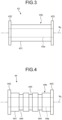
FIG. 3 is a diagram illustrating a configuration of a roller of a suspension device according to a first modification of the present invention. -
FIG. 4 is a diagram illustrating a configuration of a roller of a suspension device according to a second modification of the present invention. -
FIG. 5 is a view illustrating a configuration of a gripping member of a suspension device according to a third modification of the present invention. - Hereinafter, a mode for carrying out the present invention (hereinafter, referred to as an "embodiment") will be described with reference to the accompanying drawings. Note that the drawings are schematic, and the relationship between the thickness and the width of each portion, the ratio between the thicknesses of the respective portions, and the like may be different from actual ones, and the drawings may also include portions whose dimensional relationships and ratios differ from each other.
-
FIG. 1 is a diagram illustrating a configuration of a part of a vehicle including a suspension device according to an embodiment of the present invention. Asuspension device 1 illustrated inFIG. 1 is provided on a vehicle body of a vehicle and supports anaxle 100 that supportswheels 101. InFIG. 1 , the left side is the front of the vehicle, and the right side is the rear of the vehicle. - The
suspension device 1 includes aleaf spring 2, alocking member 3 to which one end of theleaf spring 2 is locked, and aholding member 4 that holds the other end of theleaf spring 2 in such a manner as to be movable forward and backward. - The
locking member 3 and theholding member 4 are attached to aframe 110. Specifically, thelocking member 3 is fixed to afront attachment part 120 fixed to theframe 110. Theholding member 4 is fixed to arear attachment part 130 fixed to theframe 110. Thefront attachment part 120 and therear attachment part 130 are fixed to theframe 110 by fastening members such as screws. Thelocking member 3 is attached to thefront attachment part 120 by welding or the like. Theholding member 4 is attached to therear attachment part 130 by welding or the like. Thelocking member 3 and theholding member 4 may be integrally formed with thefront attachment part 120 and therear attachment part 130, respectively. - Insertion holes (not illustrated) are formed at the center of the
leaf spring 2 in the longitudinal direction and at the center of awasher 140. Theleaf spring 2 and thewasher 140 form a leaf spring assembly fixed by fastening acenter bolt 140a inserted into the insertion holes to anut 140b. The leaf spring assembly is fixed to ahousing 160 by aU-bolt 150. - The
housing 160 is fixed to theaxle 100. -
FIG. 2 is a diagram for explaining a configuration of a leaf spring of the suspension device according to the embodiment of the present invention. Theleaf spring 2 includes amain body portion 20 formed by bending one end of a strip-shaped member, a hook-shapedfirst end portion 21 provided on one end side of themain body portion 20, and asecond end portion 22 provided on the other end side of themain body portion 20. Theaxle 100 is disposed below themain body portion 20 at the center of themain body portion 20 in the longitudinal direction. Thefirst end portion 21 is locked by being wound around thelocking member 3. Theleaf spring 2 is formed using a metal material (e.g., spring steel), a resin material, or fiber reinforced plastics (FRP). - The
holding member 4 includes two paired rollers (afirst roller 41 and a second roller 42). - The
first roller 41 includes afirst shaft part 41a connected to therear attachment part 130 and afirst rotation part 41b that is rotatable with respect to thefirst shaft part 41a. Thefirst rotation part 41b is connected to thefirst shaft part 41a, for example, via a bearing, and rotates around a central axis N1 of thefirst shaft part 41a. - The
second roller 42 includes asecond shaft part 42a connected to therear attachment part 130 and asecond rotation part 42b that is rotatable with respect to thesecond shaft part 42a. Thesecond rotation part 42b is connected to thesecond shaft part 42a, for example, via a bearing, and rotates around a central axis N2 of thesecond shaft part 42a. - The distance (gap) between the
first roller 41 and thesecond roller 42 is equal to the thickness of theleaf spring 2. Therefore, in a state where theleaf spring 2 is disposed between the rollers, thefirst roller 41 and thesecond roller 42 contact theleaf spring 2 to grip theleaf spring 2. The term "equal" used herein includes manufacturing errors and the like. - The
first shaft part 41a and thesecond shaft part 42a are formed, for example, using a metal material. Thefirst rotation part 41b and thesecond rotation part 42b are formed, for example, using a metal material, a resin material, rubber, etc. By forming the rotation parts using an elastic material such as rubber or a soft resin, a damper effect can be obtained. Furthermore, the damper effect can be adjusted by adjusting the distance between thefirst shaft part 41a and thesecond shaft part 42a. - The
first roller 41 and thesecond roller 42 correspond to a roller and a pressing member which face each other and between which an end portion of theleaf spring 2 is provided. - The
leaf spring 2 is deformed as theaxle 100 vibrates when a road surface is uneven or the like (see a broken line inFIG. 2 ). Thesecond end portion 22 is held by the holdingmember 4 by being sandwiched between thefirst roller 41 and thesecond roller 42. When thesecond end portion 22 is displaced with respect to the holdingmember 4 by the deformation of theleaf spring 2, the length of theleaf spring 2 between the lockingmember 3 and the holdingmember 4, that is, the effective span of theleaf spring 2, changes, and accordingly, the load characteristic of theleaf spring 2 changes. At this time, thefirst rotation part 41b and thesecond rotation part 42b rotate according to the displacement of thesecond end portion 22, thereby making it possible to suppress the generation of friction with thesecond end portion 22. - In the above-described embodiment of the present invention, in the
leaf spring 2 that is deformed as theaxle 100 vibrates, one end side is locked to the vehicle body (here, the frame 110), and the other end side is gripped by thefirst roller 41 and thesecond roller 42, and thefirst roller 41 and thesecond roller 42 rotate as the end portion of theleaf spring 2 on the other end side is displaced when theleaf spring 2 is deformed. According to the present embodiment, the generation of friction between theleaf spring 2 and the holdingmember 4 can be suppressed by the rotation of the rollers, suppressing a deterioration in durability and an occurrence of abnormal noise caused by the friction between the leaf spring and the holding member. - Here, in a case where an end portion of the leaf spring is held by a slide seat, if the
leaf spring 2 is broken forward of the axle, the main body of theleaf spring 2 rotates around the end connecting portion on the rear side, causing the axle to move closer to the vehicle body, resulting in a significant decrease in vehicle height. On the other hand, when theleaf spring 2 is sandwiched by the rollers as in the present embodiment, even if theleaf spring 2 is broken on the front side, a repulsive force is generated on the rear side in the sandwiched state, making it possible to suppress a significant decrease in vehicle height. - Further, according to the present embodiment, by holding the
leaf spring 2 with the rollers, theleaf spring 2 can have a nonlinear characteristic with a simple structure as compared with a conventional leaf spring in which a main spring and a sub spring are stacked. - In addition, in the present embodiment, since the thickness of the rotation part with respect to the rotation shaft is uniform, the resistance received by the leaf spring from the rollers can be uniform, thereby improving vibration-proof property and durability.
- Next, a first modification of the embodiment of the present invention will be described with reference to
FIG. 3. FIG. 3 is a diagram illustrating a configuration of a roller of a suspension device according to the first modification of the present invention. The suspension device according to the first modification includesrollers 43 instead of thefirst roller 41 and thesecond roller 42 of the holdingmember 4. Since the other components have the same configurations as those in the embodiment, the description thereof will be omitted. - The
roller 43 includes ashaft part 43a connected to therear attachment part 130 and arotation part 43b that is rotatable with respect to theshaft part 43a. Therotation part 43b is connected to theshaft part 43a, for example, via a bearing, and rotates around a central axis N3 of theshaft part 43a. - The
rotation part 43b includes amain body portion 431 having a hollow columnar shape for allowing theshaft part 43a to be inserted therethrough, afirst protrusion 432 provided on one end side of themain body portion 431 and protruding from an outer circumferential surface of themain body portion 431, and asecond protrusion 433 provided on the other end side of themain body portion 431 and protruding from the outer circumferential surface of themain body portion 431. - The
first protrusion 432 and thesecond protrusion 433 protrude to such an extent as not to interfere with protrusions of the other paired roller. The protrusions only need to protrude in a direction intersecting the direction of the central axis N3. - The
second end portion 22 of theleaf spring 2 passes between thefirst protrusion 432 and thesecond protrusion 433. - In the first modification described above, similarly to the embodiment, in the
leaf spring 2 that is deformed as theaxle 100 vibrates, one end side is locked to the vehicle body (here, the frame 110), and the other end side is gripped by the tworollers 43, and therollers 43 rotate as the end portion of theleaf spring 2 on the other end side is displaced when theleaf spring 2 is deformed. According to the first modification, the generation of friction between theleaf spring 2 and the holdingmember 4 can be suppressed by the rotation of therollers 43, suppressing a deterioration in durability and an occurrence of abnormal noise caused by the friction between the leaf spring and the holding member. - Further, according to the first modification, since the
leaf spring 2 passes between thefirst protrusion 432 and thesecond protrusion 433, it is possible to suppress displacement of theleaf spring 2 in the direction of the central axis N3. - Note that, in the first modification, one roller may be constituted by the
roller 43, and the other roller may be constituted by thefirst roller 41 or thesecond roller 42. - Further, in the first modification, the protrusion may be provided only on one end side of the
roller 43, and the protrusions of the pair of rollers may be arranged to be located on opposite sides to each other, thereby suppressing the detachment of theleaf spring 2. - In the first modification, the protrusions are provided at the end portions of the
roller 43 in the direction of the central axis N3. However, the protrusions are not necessarily provided at the end portions as long as the displacement of theleaf spring 2 in the direction of the central axis N3 can be suppressed while theleaf spring 2 is gripped by the rollers. - Next, a second modification of the embodiment of the present invention will be described with reference to
FIG. 4. FIG. 4 is a diagram illustrating a configuration of a roller of a suspension device according to the second modification of the present invention. The suspension device according to the second modification includesrollers 44 instead of thefirst roller 41 and thesecond roller 42 of the holdingmember 4. Since the other components have the same configurations as those in the embodiment, the description thereof will be omitted. - The
roller 44 includes ashaft part 44a connected to therear attachment part 130 and arotation part 44b that is rotatable with respect to theshaft part 44a. Therotation part 44b is connected to theshaft part 44a, for example, via a bearing, and rotates around a central axis N4 of theshaft part 44a. - The
rotation part 44b includes amain body portion 441 having a hollow columnar shape for allowing theshaft part 44a to be inserted therethrough, afirst protrusion 442 provided on one end side of themain body portion 441 and protruding from an outer circumferential surface of themain body portion 441, and asecond protrusion 443 provided on the other end side of themain body portion 441 and protruding from the outer circumferential surface of themain body portion 441. Thesecond end portion 22 of theleaf spring 2 passes between thefirst protrusion 442 and thesecond protrusion 443. - The
first protrusion 442 and thesecond protrusion 443 protrude to such an extent as not to interfere with protrusions of the other paired roller. The protrusions only need to protrude in a direction intersecting the direction of the central axis N4. - A plurality of
recesses 444 are formed on the outer circumferential surface of themain body portion 441. Therecesses 444 extend around themain body portion 441 in the circumferential direction. - In the second modification described above, similarly to the embodiment, in the
leaf spring 2 that is deformed as theaxle 100 vibrates, one end side is locked to the vehicle body (here, the frame 110), and the other end side is gripped by the tworollers 44, and therollers 44 rotate as the end portion of theleaf spring 2 on the other end side is displaced when theleaf spring 2 is deformed. According to the second modification, the generation of friction between theleaf spring 2 and the holdingmember 4 can be suppressed by the rotation of therollers 44, suppressing a deterioration in durability and an occurrence of abnormal noise caused by the friction between the leaf spring and the holding member. - Further, according to the second modification, since the
recesses 444 are formed around themain body portion 441, when foreign matter enters theroller 44 from the outside or foreign matter adhering to theleaf spring 2 comes to adhere to theroller 44, the foreign matter can be accommodated in therecesses 444, thereby maintaining the contact state between theleaf spring 2 and theroller 44 to suppress damage to theleaf spring 2 caused by the foreign matter. - In the second modification, one roller may be constituted by the
roller 44, and the other roller may be constituted by thefirst roller 41, thesecond roller 42, or theroller 43. - Further, in the second modification, the
roller 44 may not have protrusions. - Further, in the second modification, the plurality of
recesses 444 extending in the circumferential direction has been described as an example, but the present invention is not limited thereto. For example, onerecess 444 may be formed, a recess extending spirally around the axis N4 may be formed, or a plurality of recesses each having a hole shape (for example, through an embossing process) may be formed. - When the configuration of the second modification is applied to the configuration illustrated in
FIG. 2 , the recesses may be formed only in one roller, or may be formed in both one roller and the other roller. - Next, a third modification of the embodiment of the present invention will be described with reference to
FIG. 5. FIG. 5 is a diagram illustrating a configuration of a roller of a suspension device according to the third modification of the present invention. The suspension device according to the third modification includes a holdingmember 4A instead of the holdingmember 4. Thefirst roller 41 and thesecond roller 42 of the holdingmember 4A are attached to theframe 110 in a relatively movable manner. Since the other components have the same configurations as those in the embodiment, the description thereof will be omitted. Note that the same components are denoted by the same reference numerals. - The holding
member 4A includes two rollers (afirst roller 41 and a second roller 42), afirst spring member 45 that connects ends on one end side in the axial direction of the two rollers to each other, and asecond spring member 46 that connects ends on the other end side in the axial direction of the two rollers to each other. - The
first spring member 45 connects one end side of thefirst shaft part 41a in the direction of the axis N1 (seeFIG. 2 ) and one end side of thesecond shaft part 42a in the direction of the axis N2 (seeFIG. 2 ) in an extendable manner. - The
second spring member 46 connects the other end side of thefirst shaft part 41a in the direction of the axis N1 and the other end side of thesecond shaft part 42a in the direction of the axis N2 in an extendable manner. - In the third modification, the
first roller 41 and thesecond roller 42 are biased in directions approaching each other by the spring members that are biasing members. For example, the distance (gap) between the rollers in a natural state where no load other than gravity is applied to the spring members is equal to or smaller than the thickness of theleaf spring 2.
Therefore, in a state where theleaf spring 2 is disposed between the rollers, thefirst roller 41 and thesecond roller 42 contact theleaf spring 2 to grip theleaf spring 2. - In the third modification described above, similarly to the embodiment, in the
leaf spring 2 that is deformed as theaxle 100 vibrates, one end side is locked to the vehicle body (here, the frame 110), and the other end side is gripped by thefirst roller 41 and thesecond roller 42, and the rollers rotate as the end portion of theleaf spring 2 on the other end side is displaced when theleaf spring 2 is deformed. According to the third modification, the generation of friction between theleaf spring 2 and the holdingmember 4A can be suppressed by the rotation of each of the rollers, suppressing a deterioration in durability and an occurrence of abnormal noise caused by the friction between the leaf spring and the holding member. - In addition, according to the third modification, the spring members change the distance between the rollers while following the displacement of the
leaf spring 2, thereby suppressing theleaf spring 2 from receiving an excessive load from the rollers and preventing the smooth deformation behavior of the leaf spring from being hindered. - In the third modification, it has been described as an example that the spring members are used as members for adjusting the interval between the rollers, but the present invention is not limited thereto. For example, the interval between the rollers may be electrically controlled by an actuator.
- Although the mode for carrying out the present invention has been described so far, the present invention should not be limited only to the above-described embodiment. In the embodiment and the modifications described above, it has been described that the
axle 100 and theleaf spring 2 are connected to each other via theU-bolt 150. However, for example, theaxle 100 and theleaf spring 2 may be directly connected to each other without a U-bolt. In the embodiment and the modifications described above, it has been described that theleaf spring 2 is disposed above theaxle 100. However, theleaf spring 2 may be disposed below theaxle 100. - In an embodiment, a rotary table that supports the
first roller 41 and thesecond roller 42 may be provided on therear attachment part 130, and thefirst roller 41 and thesecond roller 42 may rotate (revolve) about the rotation axis of the rotary table. - In an embodiment, a holding
member 4 may be provided instead of the lockingmember 3, and both ends of theleaf spring 2 may be gripped by rollers. - Further, in an embodiment, one roller may be a non-rotating holding member (corresponding to the pressing member). For example, a holding member is used instead of the
second roller 42, and theleaf spring 2 is held by thefirst roller 41 and the pressing member. At this time, the holding member may have a curved surface on the side contacting theleaf spring 2, or may have a recess-formed surface on the side contacting theleaf spring 2. - Further, in an embodiment, the
first roller 41 and thesecond roller 42 may be supported by a shackle. - As described above, the present invention can include various embodiments and the like that are not described herein, and various design changes and the like can be made without departing from the technical idea specified by the claims.
- As described above, the vehicle suspension device according to the present invention is suitable for suppressing a deterioration in durability and an occurrence of abnormal noise caused by friction between the leaf spring and the holding member.
-
- 1 SUSPENSION DEVICE
- 2 LEAF SPRING
- 3 LOCKING MEMBER
- 4, 4A HOLDING MEMBER
- 41 FIRST ROLLER
- 42 SECOND ROLLER
- 43, 44 ROLLER
- 41a FIRST SHAFT PART
- 41b FIRST ROTATION PART
- 42a SECOND SHAFT PART
- 42b SECOND ROTATION PART
- 43a, 44a SHAFT PART
- 43b, 44b ROTATION PART
- 45 FIRST SPRING MEMBER
- 46 SECOND SPRING MEMBER
- 100 AXLE
- 101 WHEEL
- 110 FRAME
- 120 FRONT ATTACHMENT PART
- 130 REAR ATTACHMENT PART
- 140 WASHER
- 150 U-BOLT
- 160 HOUSING
- 431, 441 MAIN BODY PORTION
- 432, 442 FIRST PROTRUSION
- 433, 443 SECOND PROTRUSION
- 444 RECESS
Claims (8)
- A vehicle suspension device comprising:a leaf spring;a locking member to which one end of the leaf spring is locked; anda holding member configured to hold another end of the leaf spring, whereinthe holding member includes:a roller configured to hold the other end of the leaf spring and be rotatable while following displacement of the other end of the leaf spring; anda pressing member facing the roller, andthe other end of the leaf spring is provided between the roller and the pressing member.
- The vehicle suspension device according to claim 1, wherein the other end of the leaf spring is sandwiched between and held by the roller and the pressing member.
- The vehicle suspension device according to claim 1, further comprising:
a biasing member configured to bias the roller and the pressing member in a direction in which the roller and the pressing member approach each other. - The vehicle suspension device according to claim 1, wherein the pressing member is a roller that is rotatable while following displacement of the other end of the leaf spring.
- The vehicle suspension device according to claim 1, wherein at least one recess is formed on an outer circumferential surface of the roller.
- The vehicle suspension device according to claim 4, wherein at least one recess is formed on an outer circumferential surface of at least one of the roller and the pressing member.
- The vehicle suspension device according to claim 1, wherein the roller includes:a shaft part; anda rotation part provided on an outer circumference of the shaft part, and configured to be rotatable with respect to the shaft part, the rotation part including an elastic material.
- The vehicle suspension device according to claim 1, wherein a protrusion protruding in a direction intersecting an axial direction is formed on at least one end side in the axial direction of the roller.
Applications Claiming Priority (2)
| Application Number | Priority Date | Filing Date | Title |
|---|---|---|---|
| JP2022092887A JP2023179932A (en) | 2022-06-08 | 2022-06-08 | Vehicle suspension system |
| PCT/JP2023/016929 WO2023238553A1 (en) | 2022-06-08 | 2023-04-28 | Vehicle suspension device |
Publications (2)
| Publication Number | Publication Date |
|---|---|
| EP4538069A1 true EP4538069A1 (en) | 2025-04-16 |
| EP4538069A4 EP4538069A4 (en) | 2025-09-17 |
Family
ID=89118133
Family Applications (1)
| Application Number | Title | Priority Date | Filing Date |
|---|---|---|---|
| EP23819540.8A Pending EP4538069A4 (en) | 2022-06-08 | 2023-04-28 | VEHICLE SUSPENSION DEVICE |
Country Status (6)
| Country | Link |
|---|---|
| US (1) | US20250332877A1 (en) |
| EP (1) | EP4538069A4 (en) |
| JP (1) | JP2023179932A (en) |
| CN (1) | CN119255923A (en) |
| MX (1) | MX2024014738A (en) |
| WO (1) | WO2023238553A1 (en) |
Families Citing this family (1)
| Publication number | Priority date | Publication date | Assignee | Title |
|---|---|---|---|---|
| WO2025127095A1 (en) * | 2023-12-13 | 2025-06-19 | 日本発條株式会社 | Vehicle suspension system |
Family Cites Families (12)
| Publication number | Priority date | Publication date | Assignee | Title |
|---|---|---|---|---|
| US1859104A (en) * | 1929-05-07 | 1932-05-17 | Munro Thomas | Spring suspension of vehicles |
| US1936258A (en) * | 1930-02-10 | 1933-11-21 | Nielsen Edward Jam Westergaard | Spring shackle |
| GB569483A (en) * | 1943-06-22 | 1945-05-25 | Leslie Mark Ballamy | Improvements in or relating to attachments of leaf springs |
| JPS58115406U (en) * | 1982-01-30 | 1983-08-06 | いすゞ自動車株式会社 | Vehicle suspension system |
| JPS5913305U (en) * | 1982-07-20 | 1984-01-27 | 三菱自動車工業株式会社 | Rubber roller for leaf spring stop |
| JPS5947507U (en) * | 1982-09-24 | 1984-03-29 | 三菱自動車工業株式会社 | Leaf spring suspension |
| JPS61169307A (en) | 1985-01-23 | 1986-07-31 | Hitachi Metals Ltd | Slide sheet |
| US5024462A (en) * | 1989-05-09 | 1991-06-18 | Daniel Assh | Combined air and leaf spring suspension for heavy weight vehicle |
| JPH0735836U (en) * | 1993-12-08 | 1995-07-04 | 日野自動車工業株式会社 | Silencer for leaf spring |
| JP2006027552A (en) * | 2004-07-21 | 2006-02-02 | Nissan Motor Co Ltd | Suspension device stiffness control mechanism |
| WO2017014709A1 (en) * | 2015-07-23 | 2017-01-26 | Ford Otomotiv Sanayi Anonim Sirketi | A spring bracket |
| KR102322264B1 (en) * | 2017-09-21 | 2021-11-04 | 현대자동차 주식회사 | Suspension for vehicle |
-
2022
- 2022-06-08 JP JP2022092887A patent/JP2023179932A/en active Pending
-
2023
- 2023-04-28 EP EP23819540.8A patent/EP4538069A4/en active Pending
- 2023-04-28 WO PCT/JP2023/016929 patent/WO2023238553A1/en not_active Ceased
- 2023-04-28 CN CN202380040325.XA patent/CN119255923A/en active Pending
- 2023-04-28 US US18/871,599 patent/US20250332877A1/en active Pending
-
2024
- 2024-11-28 MX MX2024014738A patent/MX2024014738A/en unknown
Also Published As
| Publication number | Publication date |
|---|---|
| EP4538069A4 (en) | 2025-09-17 |
| WO2023238553A1 (en) | 2023-12-14 |
| CN119255923A (en) | 2025-01-03 |
| US20250332877A1 (en) | 2025-10-30 |
| MX2024014738A (en) | 2025-01-09 |
| JP2023179932A (en) | 2023-12-20 |
Similar Documents
| Publication | Publication Date | Title |
|---|---|---|
| US8973507B2 (en) | Bogie for guide rail type vehicle | |
| US11260713B2 (en) | Bush | |
| WO2007126359A1 (en) | Stabiliser bar for a vehicle | |
| US20250332877A1 (en) | Vehicle suspension device | |
| WO2009104815A1 (en) | Vehicle stabilizer | |
| CN107364279B (en) | Vehicles and their omnidirectional wheels | |
| CN207106029U (en) | Vehicle and omni wheel thereof | |
| JP6148897B2 (en) | Stabilizer bush | |
| CN207106036U (en) | Omnidirectional wheel | |
| US4966472A (en) | Roller bushing | |
| CN107444008B (en) | omnidirectional wheel | |
| WO2025127096A1 (en) | Vehicle suspension device | |
| US20120248725A1 (en) | Suspension system with articulation compliant spring beam bushing | |
| WO2025126984A1 (en) | Vehicle suspension device | |
| WO2006112574A1 (en) | Spring wheel | |
| JP3130323U (en) | Omnidirectional wheel | |
| WO2025127067A1 (en) | Vehicular suspension device | |
| JP4983106B2 (en) | Stabilizer device | |
| CN207106030U (en) | Elastic damping part and omni-directional moving wheel comprising same | |
| KR102070384B1 (en) | Semi-active Anti-roll Stabilizer Bar | |
| JP5126373B2 (en) | Stabilizer device | |
| JP4214846B2 (en) | Steering device and electric power steering device | |
| KR20110062009A (en) | Deputy Mayor Structure for Vehicles | |
| JP5416993B2 (en) | Non pneumatic tire | |
| KR100857363B1 (en) | Adjustable torsion bar with CT suspension |
Legal Events
| Date | Code | Title | Description |
|---|---|---|---|
| STAA | Information on the status of an ep patent application or granted ep patent |
Free format text: STATUS: THE INTERNATIONAL PUBLICATION HAS BEEN MADE |
|
| PUAI | Public reference made under article 153(3) epc to a published international application that has entered the european phase |
Free format text: ORIGINAL CODE: 0009012 |
|
| STAA | Information on the status of an ep patent application or granted ep patent |
Free format text: STATUS: REQUEST FOR EXAMINATION WAS MADE |
|
| 17P | Request for examination filed |
Effective date: 20241127 |
|
| AK | Designated contracting states |
Kind code of ref document: A1 Designated state(s): AL AT BE BG CH CY CZ DE DK EE ES FI FR GB GR HR HU IE IS IT LI LT LU LV MC ME MK MT NL NO PL PT RO RS SE SI SK SM TR |
|
| A4 | Supplementary search report drawn up and despatched |
Effective date: 20250818 |
|
| DAV | Request for validation of the european patent (deleted) | ||
| DAX | Request for extension of the european patent (deleted) | ||
| RIC1 | Information provided on ipc code assigned before grant |
Ipc: B60G 11/107 20060101AFI20250811BHEP Ipc: B60G 11/04 20060101ALI20250811BHEP Ipc: F16F 1/18 20060101ALI20250811BHEP Ipc: F16F 1/26 20060101ALI20250811BHEP |