EP4538014A1 - Resin tube manufacturing method and device - Google Patents
Resin tube manufacturing method and device Download PDFInfo
- Publication number
- EP4538014A1 EP4538014A1 EP23823531.1A EP23823531A EP4538014A1 EP 4538014 A1 EP4538014 A1 EP 4538014A1 EP 23823531 A EP23823531 A EP 23823531A EP 4538014 A1 EP4538014 A1 EP 4538014A1
- Authority
- EP
- European Patent Office
- Prior art keywords
- cavity
- resin
- end portion
- molten resin
- pipe
- Prior art date
- Legal status (The legal status is an assumption and is not a legal conclusion. Google has not performed a legal analysis and makes no representation as to the accuracy of the status listed.)
- Pending
Links
Images



Classifications
-
- B—PERFORMING OPERATIONS; TRANSPORTING
- B29—WORKING OF PLASTICS; WORKING OF SUBSTANCES IN A PLASTIC STATE IN GENERAL
- B29C—SHAPING OR JOINING OF PLASTICS; SHAPING OF MATERIAL IN A PLASTIC STATE, NOT OTHERWISE PROVIDED FOR; AFTER-TREATMENT OF THE SHAPED PRODUCTS, e.g. REPAIRING
- B29C45/00—Injection moulding, i.e. forcing the required volume of moulding material through a nozzle into a closed mould; Apparatus therefor
- B29C45/17—Component parts, details or accessories; Auxiliary operations
- B29C45/1703—Introducing an auxiliary fluid into the mould
- B29C45/1704—Introducing an auxiliary fluid into the mould the fluid being introduced into the interior of the injected material which is still in a molten state, e.g. for producing hollow articles
- B29C45/1711—Introducing an auxiliary fluid into the mould the fluid being introduced into the interior of the injected material which is still in a molten state, e.g. for producing hollow articles and removing excess material from the mould cavity by the introduced fluid, e.g. to an overflow cavity
-
- B—PERFORMING OPERATIONS; TRANSPORTING
- B29—WORKING OF PLASTICS; WORKING OF SUBSTANCES IN A PLASTIC STATE IN GENERAL
- B29C—SHAPING OR JOINING OF PLASTICS; SHAPING OF MATERIAL IN A PLASTIC STATE, NOT OTHERWISE PROVIDED FOR; AFTER-TREATMENT OF THE SHAPED PRODUCTS, e.g. REPAIRING
- B29C45/00—Injection moulding, i.e. forcing the required volume of moulding material through a nozzle into a closed mould; Apparatus therefor
- B29C45/0005—Injection moulding, i.e. forcing the required volume of moulding material through a nozzle into a closed mould; Apparatus therefor using fibre reinforcements
-
- B—PERFORMING OPERATIONS; TRANSPORTING
- B29—WORKING OF PLASTICS; WORKING OF SUBSTANCES IN A PLASTIC STATE IN GENERAL
- B29C—SHAPING OR JOINING OF PLASTICS; SHAPING OF MATERIAL IN A PLASTIC STATE, NOT OTHERWISE PROVIDED FOR; AFTER-TREATMENT OF THE SHAPED PRODUCTS, e.g. REPAIRING
- B29C45/00—Injection moulding, i.e. forcing the required volume of moulding material through a nozzle into a closed mould; Apparatus therefor
- B29C45/17—Component parts, details or accessories; Auxiliary operations
- B29C45/18—Feeding the material into the injection moulding apparatus, i.e. feeding the non-plastified material into the injection unit
- B29C45/1816—Feeding auxiliary material, e.g. colouring material
-
- B—PERFORMING OPERATIONS; TRANSPORTING
- B29—WORKING OF PLASTICS; WORKING OF SUBSTANCES IN A PLASTIC STATE IN GENERAL
- B29D—PRODUCING PARTICULAR ARTICLES FROM PLASTICS OR FROM SUBSTANCES IN A PLASTIC STATE
- B29D23/00—Producing tubular articles
- B29D23/001—Pipes; Pipe joints
-
- B—PERFORMING OPERATIONS; TRANSPORTING
- B29—WORKING OF PLASTICS; WORKING OF SUBSTANCES IN A PLASTIC STATE IN GENERAL
- B29C—SHAPING OR JOINING OF PLASTICS; SHAPING OF MATERIAL IN A PLASTIC STATE, NOT OTHERWISE PROVIDED FOR; AFTER-TREATMENT OF THE SHAPED PRODUCTS, e.g. REPAIRING
- B29C45/00—Injection moulding, i.e. forcing the required volume of moulding material through a nozzle into a closed mould; Apparatus therefor
- B29C45/17—Component parts, details or accessories; Auxiliary operations
- B29C45/1703—Introducing an auxiliary fluid into the mould
- B29C45/1704—Introducing an auxiliary fluid into the mould the fluid being introduced into the interior of the injected material which is still in a molten state, e.g. for producing hollow articles
- B29C45/1706—Introducing an auxiliary fluid into the mould the fluid being introduced into the interior of the injected material which is still in a molten state, e.g. for producing hollow articles using particular fluids or fluid generating substances
- B29C2045/1707—Introducing an auxiliary fluid into the mould the fluid being introduced into the interior of the injected material which is still in a molten state, e.g. for producing hollow articles using particular fluids or fluid generating substances using a liquid, e.g. water
-
- B—PERFORMING OPERATIONS; TRANSPORTING
- B29—WORKING OF PLASTICS; WORKING OF SUBSTANCES IN A PLASTIC STATE IN GENERAL
- B29C—SHAPING OR JOINING OF PLASTICS; SHAPING OF MATERIAL IN A PLASTIC STATE, NOT OTHERWISE PROVIDED FOR; AFTER-TREATMENT OF THE SHAPED PRODUCTS, e.g. REPAIRING
- B29C45/00—Injection moulding, i.e. forcing the required volume of moulding material through a nozzle into a closed mould; Apparatus therefor
- B29C45/17—Component parts, details or accessories; Auxiliary operations
- B29C45/1703—Introducing an auxiliary fluid into the mould
- B29C45/1704—Introducing an auxiliary fluid into the mould the fluid being introduced into the interior of the injected material which is still in a molten state, e.g. for producing hollow articles
- B29C45/1711—Introducing an auxiliary fluid into the mould the fluid being introduced into the interior of the injected material which is still in a molten state, e.g. for producing hollow articles and removing excess material from the mould cavity by the introduced fluid, e.g. to an overflow cavity
- B29C2045/1712—Introducing an auxiliary fluid into the mould the fluid being introduced into the interior of the injected material which is still in a molten state, e.g. for producing hollow articles and removing excess material from the mould cavity by the introduced fluid, e.g. to an overflow cavity plastic material flowing back into the injection unit
-
- B—PERFORMING OPERATIONS; TRANSPORTING
- B29—WORKING OF PLASTICS; WORKING OF SUBSTANCES IN A PLASTIC STATE IN GENERAL
- B29C—SHAPING OR JOINING OF PLASTICS; SHAPING OF MATERIAL IN A PLASTIC STATE, NOT OTHERWISE PROVIDED FOR; AFTER-TREATMENT OF THE SHAPED PRODUCTS, e.g. REPAIRING
- B29C45/00—Injection moulding, i.e. forcing the required volume of moulding material through a nozzle into a closed mould; Apparatus therefor
- B29C45/17—Component parts, details or accessories; Auxiliary operations
- B29C45/1703—Introducing an auxiliary fluid into the mould
- B29C45/1704—Introducing an auxiliary fluid into the mould the fluid being introduced into the interior of the injected material which is still in a molten state, e.g. for producing hollow articles
- B29C2045/1719—Introducing an auxiliary fluid into the mould the fluid being introduced into the interior of the injected material which is still in a molten state, e.g. for producing hollow articles making tubular articles
-
- B—PERFORMING OPERATIONS; TRANSPORTING
- B29—WORKING OF PLASTICS; WORKING OF SUBSTANCES IN A PLASTIC STATE IN GENERAL
- B29C—SHAPING OR JOINING OF PLASTICS; SHAPING OF MATERIAL IN A PLASTIC STATE, NOT OTHERWISE PROVIDED FOR; AFTER-TREATMENT OF THE SHAPED PRODUCTS, e.g. REPAIRING
- B29C70/00—Shaping composites, i.e. plastics material comprising reinforcements, fillers or preformed parts, e.g. inserts
- B29C70/04—Shaping composites, i.e. plastics material comprising reinforcements, fillers or preformed parts, e.g. inserts comprising reinforcements only, e.g. self-reinforcing plastics
- B29C70/06—Fibrous reinforcements only
-
- B—PERFORMING OPERATIONS; TRANSPORTING
- B29—WORKING OF PLASTICS; WORKING OF SUBSTANCES IN A PLASTIC STATE IN GENERAL
- B29K—INDEXING SCHEME ASSOCIATED WITH SUBCLASSES B29B, B29C OR B29D, RELATING TO MOULDING MATERIALS OR TO MATERIALS FOR MOULDS, REINFORCEMENTS, FILLERS OR PREFORMED PARTS, e.g. INSERTS
- B29K2105/00—Condition, form or state of moulded material or of the material to be shaped
- B29K2105/06—Condition, form or state of moulded material or of the material to be shaped containing reinforcements, fillers or inserts
-
- B—PERFORMING OPERATIONS; TRANSPORTING
- B29—WORKING OF PLASTICS; WORKING OF SUBSTANCES IN A PLASTIC STATE IN GENERAL
- B29L—INDEXING SCHEME ASSOCIATED WITH SUBCLASS B29C, RELATING TO PARTICULAR ARTICLES
- B29L2023/00—Tubular articles
- B29L2023/004—Bent tubes
-
- B—PERFORMING OPERATIONS; TRANSPORTING
- B29—WORKING OF PLASTICS; WORKING OF SUBSTANCES IN A PLASTIC STATE IN GENERAL
- B29L—INDEXING SCHEME ASSOCIATED WITH SUBCLASS B29C, RELATING TO PARTICULAR ARTICLES
- B29L2023/00—Tubular articles
- B29L2023/22—Tubes or pipes, i.e. rigid
Definitions
- the present invention relates to a method and a device for manufacturing a resin pipe.
- a gas assist molding method which includes injecting a molten resin into a cavity of a mold and subsequently introducing a high-pressure gas, such as a nitrogen gas, into the cavity (see, for example, Patent Document 1).
- a high-pressure gas such as a nitrogen gas
- a solid such as a metal ball or a resin ball may be introduced, as an assist material, into the cavity at a high pressure.
- Patent Document 1 JP 2003-181868 A
- a method for manufacturing a resin pipe by injecting a molten resin from one end portion toward an other end portion of a cavity extending in a mold by an injector, and then introducing a fluid or solid assist material into the cavity to discharge an extra molten resin of the molten resin from the cavity, thereby curing the molten resin in a cylindrical shape remaining in the cavity, the method including: introducing the assist material from the other end portion toward the one end portion of the cavity to cause the extra molten resin discharged from the cavity to flow back into the injector; and injecting the back-flowed molten resin from the one end portion toward the other end portion of the cavity by the injector when manufacturing a next new resin pipe.
- the extra molten resin discharged from the cavity by introducing the assist material into the cavity is caused to flow back into the injector and can be used when manufacturing a next new resin pipe. Therefore, the resin to be discarded is suppressed, and the resin can be more effectively reused. This is also advantageous in reducing the energy required for reusing the resin.
- the injector 2 includes a cylinder 3 and a screw 4 provided inside the cylinder 3.
- the injector 2 is not limited to the type shown in the drawing, and various known resin injection molding machines such as a pre-plasticizing type can be used.
- An injection path 9a is connected to an injection outlet 3a at a tip of the cylinder 3.
- the injection path 9a is connected to the mold 7.
- the resin to be used is heated and melted inside the cylinder 3, and the molten resin R1 is injected from the injection outlet 3a toward the inside of the mold 7 by the rotating (forward rotating) screw 4.
- an appropriate type of resin is selected from various known resins that can be injected, depending on the performance or the like required for the resin pipe 10.
- polyamide, polyphenylene sulfide, polypropylene, ABS resin, or the like is used, and nylon resin (such as 66 nylon) is suitably used.
- various fibers for example, short fibers or long fibers such as glass fibers or carbon fibers
- the short fibers are sized to have, for example, an outer diameter of about 0.001 mm or greater and 1.0 mm or less and a length of about 0.01 mm or greater and 10 mm or less.
- the molten resin R1 mixed with reinforcing fibers f is used.
- the assist material injection device 5 includes a housing portion 6 in which a fluid (gas or liquid) or solid assist material As is accommodated.
- a fluid gas or liquid
- solid assist material As the assist material injection device 5, various known injection devices can be used.
- an appropriate known material is selected from a gas such as nitrogen gas or air, a liquid such as water or oil, or a solid such as a metal ball or a resin ball.
- An introduction path 9b is connected to an introduction outlet 6a at a tip of the housing portion 6.
- the introduction path 9b is connected to the mold 7.
- the assist material As is introduced from the introduction outlet 6a toward the inside of the mold 7 at a predetermined pressure.
- a cavity 8 that is a hollow cavity is formed in the mold 7.
- the cavity 8 extends from one end portion 8a to the other end portion 8b in a shape identical to that of the resin pipe 10 to be manufactured.
- An injection outlet 3a is connected to the one end portion 8a of the cavity 8 via the injection path 9a, and the introduction outlet 6a is connected to the other end portion 8b via the introduction path 9b.
- the injection outlet 3a may be indirectly or directly connected to the one end portion 8a of the cavity 8, and the introduction outlet 6a may be indirectly or directly connected to the other end portion 8b of the cavity 8.
- the molten resin R1 discharged from the cavity 8 is cured as it is without flowing back into the injector 2. Along with this, a large amount of useless portions of the cured resin R2 are generated. However, according to the manufacturing method described above, the amount of useless portions of the cured resin R2 can be suppressed.
- the molten resin R1 mixed with the reinforcing fibers f is used as in this embodiment, it is difficult to reuse the cured resin R2 because the reinforcing fibers f are included in the cured resin R2.
- the above-described manufacturing method is particularly effective in effectively using the resin without wasting it, and is very effective in suppressing the material (resin) cost in the case of an expensive resin.
- the extra molten resin R1 discharged from the cavity 8 is subsequently used as an injection material in the molding step. Therefore, it is not necessary to perform a processing step of pelletizing the generated useless portions of the cured resin R2 in order to reuse the useless portions or to melt the pellets thereafter, which is advantageous in suppressing energy required for reusing the resins.
Landscapes
- Engineering & Computer Science (AREA)
- Mechanical Engineering (AREA)
- Manufacturing & Machinery (AREA)
- Injection Moulding Of Plastics Or The Like (AREA)
- Moulds For Moulding Plastics Or The Like (AREA)
- Moulding By Coating Moulds (AREA)
Abstract
Provided are a method and a device for manufacturing a resin pipe that can more effectively use a resin in molding the resin pipe by resin injection molding using an assist material. A resin pipe (10) is manufactured by injecting a molten resin (R1) from one end portion (8a) toward the other end portion (8b) of a cavity (8) formed in a mold (7) by an injector (2) and filling the molten resin (R1) in the cavity (8), and then introducing a fluid or solid assist material (As) by an assist material injection device (5) from the other end portion (8b) toward the one end portion (8a) of the cavity (8) to discharge an extra molten resin (R1) from the cavity (8), thereby curing the molten resin (R1) in a cylindrical shape remaining in the cavity (8). The extra molten resin (R1) discharged from the cavity (8) is caused to flow back into the injector (2), and the back-flowed molten resin (R1) is injected and used from the one end portion (8a) toward the other end portion (8b) of the cavity (8) by the injector (2) when manufacturing a next new resin pipe (10).
Description
- The present invention relates to a method and a device for manufacturing a resin pipe.
- As a method for molding a resin pipe by resin injection molding, a gas assist molding method is known which includes injecting a molten resin into a cavity of a mold and subsequently introducing a high-pressure gas, such as a nitrogen gas, into the cavity (see, for example, Patent Document 1). Instead of the high-pressure gas, a solid such as a metal ball or a resin ball may be introduced, as an assist material, into the cavity at a high pressure.
- When manufacturing the resin pipe by the resin injection molding using the assist material in this manner, an extra molten resin is discharged from the cavity by the assist material introduced into the cavity. The molten resin discharged from the cavity is then solidified. The solidified resin is, for example, pelletized and reused. However, in order to reuse the resin, a processing step of pelletizing the solidified resin is required, and in the subsequent molding step, the pellets need to be heated and melted, which requires a corresponding amount of energy. In addition, when a reinforcing material such as a reinforcing fiber is mixed in the solidified resin, it is difficult to reuse the resin, and it may be necessary to dispose of the resin in some cases. Therefore, there is room for improvement for more effectively using the resin used in the resin injection molding using the assist material.
- Patent Document 1:
JP 2003-181868 A - An object of the present invention is to provide a method and a device for manufacturing a resin pipe that can more effectively use a resin in molding the resin pipe by resin injection molding using an assist material.
- In order to achieve the above object, according to an aspect of the present invention, there is provided a method for manufacturing a resin pipe by injecting a molten resin from one end portion toward an other end portion of a cavity extending in a mold by an injector, and then introducing a fluid or solid assist material into the cavity to discharge an extra molten resin of the molten resin from the cavity, thereby curing the molten resin in a cylindrical shape remaining in the cavity, the method including: introducing the assist material from the other end portion toward the one end portion of the cavity to cause the extra molten resin discharged from the cavity to flow back into the injector; and injecting the back-flowed molten resin from the one end portion toward the other end portion of the cavity by the injector when manufacturing a next new resin pipe.
- According to another aspect of the present invention, there is provided a device for manufacturing a resin pipe, including: a mold including a cavity extending in the mold; an injector including an injection outlet connected to one end portion of the cavity and configured to inject a molten resin from the one end portion toward an other end portion of the cavity; and an assist material injection device configured to introduce a fluid or solid assist material into the cavity filled with the molten resin, in which an introduction outlet of the assist material injection device is connected to the other end portion of the cavity, the assist material is introduced from the other end portion toward the one end portion of the cavity to cause an extra molten resin of the molten resin from the cavity to flow back into the injector, and the back-flowed molten resin is injected from the one end portion toward the other end portion of the cavity by the injector when manufacturing a next new resin pipe.
- According to the present invention, the extra molten resin discharged from the cavity by introducing the assist material into the cavity is caused to flow back into the injector and can be used when manufacturing a next new resin pipe. Therefore, the resin to be discarded is suppressed, and the resin can be more effectively reused. This is also advantageous in reducing the energy required for reusing the resin.
-
-
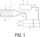
FIG. 1 is an explanatory diagram illustrating a device for manufacturing a resin pipe. -
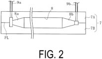
FIG. 2 is an explanatory diagram illustrating a mold ofFIG. 1 in a longitudinal cross-sectional view. -
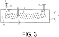
FIG. 3 is an explanatory diagram illustrating a state in which a molten resin is injected and filled into a cavity ofFIG. 2 . -
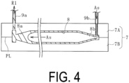
FIG. 4 is an explanatory diagram illustrating a state in which an assist material is injected into the cavity ofFIG. 3 . -
FIG. 5 is an explanatory diagram illustrating a resin pipe molded in the cavity ofFIG. 4 . -
FIG. 6 is an explanatory diagram illustrating a manufactured resin pipe in a longitudinal cross-sectional view. -
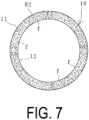
FIG. 7 is an explanatory diagram illustrating the resin pipe ofFIG. 6 in a transverse cross-sectional view. -
FIG. 8 is an explanatory diagram illustrating another resin pipe in a plan view. - A method and a device for manufacturing a resin pipe according to an embodiment of the present invention will be described below based on an embodiment illustrated in the drawings.
- The embodiment of a
manufacturing device 1 of a resin pipe illustrated inFIGS. 1 and2 includes aninjector 2, an assistmaterial injection device 5, and amold 7. Aresin pipe 10 illustrated inFIGS. 6 and7 is manufactured using themanufacturing device 1. Theresin pipe 10 is a cylindrical body including aperipheral wall 11 formed by a cured resin R2, and includes apipe passage 12 extending in a longitudinal direction. A dot-dash line CL in the drawings indicates a center line passing through a center of a transverse cross-section of the resin pipe 10 (pipe passage 12). - Although a size of the
resin pipe 10 to be manufactured is not particularly limited, an outer diameter is, for example, about 5 mm or greater and 30 mm or less, and a thickness of theperipheral wall 11 is, for example, about 1 mm or greater and 5 mm or less. Theresin pipe 10 includes reinforcing fibers f scattered in the cured resin R2. However, since the reinforcing fibers f are arbitrarily used, it is also possible to manufacture theresin pipe 10 in which the reinforcing fibers f are not present in the cured resin R2. Note that in the drawings, the reinforcing fibers f are shown in an exaggerated manner. - The
injector 2 includes acylinder 3 and ascrew 4 provided inside thecylinder 3. Theinjector 2 is not limited to the type shown in the drawing, and various known resin injection molding machines such as a pre-plasticizing type can be used. Aninjection path 9a is connected to an injection outlet 3a at a tip of thecylinder 3. Theinjection path 9a is connected to themold 7. The resin to be used is heated and melted inside thecylinder 3, and the molten resin R1 is injected from the injection outlet 3a toward the inside of themold 7 by the rotating (forward rotating)screw 4. - For the resin used as the molten resin R1, an appropriate type of resin is selected from various known resins that can be injected, depending on the performance or the like required for the
resin pipe 10. For example, when manufacturing theresin pipe 10 for an air conditioner to be mounted on an automobile, polyamide, polyphenylene sulfide, polypropylene, ABS resin, or the like is used, and nylon resin (such as 66 nylon) is suitably used. - As the reinforcing fibers S, various fibers (for example, short fibers or long fibers such as glass fibers or carbon fibers) can be mixed at a predetermined ratio (for example, 30% parts by mass or more and 40% parts by mass or less per 100 parts by mass of the resin). The short fibers are sized to have, for example, an outer diameter of about 0.001 mm or greater and 1.0 mm or less and a length of about 0.01 mm or greater and 10 mm or less. In this embodiment, the molten resin R1 mixed with reinforcing fibers f is used.
- The assist
material injection device 5 includes a housing portion 6 in which a fluid (gas or liquid) or solid assist material As is accommodated. As the assistmaterial injection device 5, various known injection devices can be used. For the assist material As, an appropriate known material is selected from a gas such as nitrogen gas or air, a liquid such as water or oil, or a solid such as a metal ball or a resin ball. - An
introduction path 9b is connected to anintroduction outlet 6a at a tip of the housing portion 6. Theintroduction path 9b is connected to themold 7. The assist material As is introduced from theintroduction outlet 6a toward the inside of themold 7 at a predetermined pressure. - The
mold 7 is constituted of onemold 7A and theother mold 7B assembled to each other. Themolds piece mold 7 is used in this embodiment, various other known types ofmolds 7 can be used. - A
cavity 8 that is a hollow cavity is formed in themold 7. Thecavity 8 extends from oneend portion 8a to theother end portion 8b in a shape identical to that of theresin pipe 10 to be manufactured. An injection outlet 3a is connected to the oneend portion 8a of thecavity 8 via theinjection path 9a, and theintroduction outlet 6a is connected to theother end portion 8b via theintroduction path 9b. The injection outlet 3a may be indirectly or directly connected to the oneend portion 8a of thecavity 8, and theintroduction outlet 6a may be indirectly or directly connected to theother end portion 8b of thecavity 8. - Next, an example of a procedure of a method for manufacturing the
resin pipe 10 using themanufacturing device 1 will be described. - As illustrated in
FIG. 2 , in a state in which themolds mold 7 by theinjector 2. As illustrated inFIG. 3 , the injected molten resin R1 is injected from the injection outlet 3a into thecavity 8 via theinjection path 9a. Specifically, the molten resin R1 is injected from the oneend portion 8a toward theother end portion 8b of thecavity 8, and thecavity 8 is filled with the molten resin R1. Note that inFIGS. 3 to 5 , the reinforcing fibers f mixed in the molten resin R1 are not shown. - Next, the assist material As is introduced into the
mold 7 by the assistmaterial injection device 5. That is, as illustrated inFIG. 4 , the assist material As is introduced at a predetermined pressure from theother end portion 8b toward the oneend portion 8a of thecavity 8 filled with the molten resin R1. The introduced assist material As passes through the inside of thecavity 8 along the extending direction of thecavity 8 at a predetermined pressure. - When the assist material As passes through the inside of the
cavity 8, the extra molten resin R1 is discharged from the oneend portion 8a of thecavity 8, and the molten resin R1 adhering to thecavity 8 remains in a cylindrical shape in thecavity 8. When the assist material As is introduced from the assistmaterial injection device 5, theinjector 2 retracts thescrew 4 to cause the molten resin R1 discharged from thecavity 8 to flow back into thecylinder 3 via theinjection path 9a. - As illustrated in
FIG. 5 , the remaining molten resin R1 is cured inside thecavity 8. Thus, theresin pipe 10 is molded by the cured resin R2. Useless portions of the cured resin R2 (portions that do not form the resin pipe 10) are integrated with both end portions of theresin pipe 10. - Next, the
molds mold 7, and the moldedresin pipe 10 is taken out together with the useless portions of the cured resin R2. As a result, thecavity 8 is in an empty state. Theresin pipe 10 illustrated inFIGS. 6 and7 is manufactured by cutting off the useless portions of the cured resin R2 from the taken outresin pipe 10. - In the
mold 7 in which thecavity 8 is in an empty state, a nextnew resin pipe 10 is subsequently continuously manufactured. Then, the molten resin R1 flowed back into thecylinder 3 is injected from the oneend portion 8a toward theother end portion 8b of thecavity 8 as illustrated inFIG. 3 in the same procedure as described above. Next, as illustrated inFIG. 4 , the assist material As is introduced at a predetermined pressure from theother end portion 8b toward the oneend portion 8a of thecavity 8 filled with the molten resin R1 in the same procedure as described above. As a result, anew resin pipe 10 is molded, and the extra molten resin R1 discharged from thecavity 8 is caused to flow back into thecylinder 3 via theinjection path 9a. - In this manufacturing method, the extra molten resin R1 discharged from the
cavity 8 by introducing the assist material As into thecavity 8 is caused to flow back into theinjector 2 and can be used when manufacturing a nextnew resin pipe 10. Therefore, the resin to be discarded is suppressed, and the resin can be more effectively reused. - If the assist material As is introduced from the one
end portion 8a toward theother end portion 8b of thecavity 8 as in the related art, the molten resin R1 discharged from thecavity 8 is cured as it is without flowing back into theinjector 2. Along with this, a large amount of useless portions of the cured resin R2 are generated. However, according to the manufacturing method described above, the amount of useless portions of the cured resin R2 can be suppressed. When the molten resin R1 mixed with the reinforcing fibers f is used as in this embodiment, it is difficult to reuse the cured resin R2 because the reinforcing fibers f are included in the cured resin R2. However, the above-described manufacturing method is particularly effective in effectively using the resin without wasting it, and is very effective in suppressing the material (resin) cost in the case of an expensive resin. - In addition, in the above-described manufacturing method, the extra molten resin R1 discharged from the
cavity 8 is subsequently used as an injection material in the molding step. Therefore, it is not necessary to perform a processing step of pelletizing the generated useless portions of the cured resin R2 in order to reuse the useless portions or to melt the pellets thereafter, which is advantageous in suppressing energy required for reusing the resins. - Although the
resin pipe 10 manufactured in the above-described embodiment is a straight pipe in which thepipe passage 12 is linear, the shape of theresin pipe 10 is not particularly limited. Since theresin pipe 10 is molded using the assist material As, it is suitable for manufacturing a non-straight pipe including thepipe passage 12 that is bent as theresin pipe 10 illustrated inFIG. 8 . In the above-described manufacturing method, even theresin pipe 10 including a plurality of bent portions can be manufactured with high productivity. -
- 1 Manufacturing device of resin pipe
- 2 Injector
- 3 Cylinder
- 3a Injection outlet
- 4 Screw
- 5 Assist material injection device
- 6 Housing portion
- 6a Introduction outlet
- 7 (7A, 7B) Mold
- 8 Cavity
- 8a One end portion
- 8b Other end portion
- 9a Injection path
- 9b Introduction path
- 10 Resin pipe
- 11 Peripheral wall
- 12 Pipe passage
- R1 Molten resin
- R2 Cured resin
- As Assist material
- f Reinforcing fiber
Claims (4)
- A method for manufacturing a resin pipe by injecting a molten resin from one end portion toward an other end portion of a cavity extending in a mold by an injector, and then introducing a fluid or solid assist material into the cavity to discharge an extra molten resin of the molten resin from the cavity, thereby curing the molten resin in a cylindrical shape remaining in the cavity, the method comprising:introducing the assist material from the other end portion toward the one end portion of the cavity to cause the extra molten resin discharged from the cavity to flow back into the injector; andinjecting the back-flowed molten resin from the one end portion toward the other end portion of the cavity by the injector when manufacturing a next new resin pipe.
- The method for manufacturing a resin pipe according to claim 1, wherein the molten resin mixed with reinforcing fibers is used.
- The method for manufacturing a resin pipe according to claim 1 or 2, wherein the resin pipe is a non-straight pipe comprising a pipe passage that is bent.
- A device for manufacturing a resin pipe, comprising:a mold comprising a cavity extending in the mold;an injector comprising an injection outlet connected to one end portion of the cavity and configured to inject a molten resin from the one end portion toward an other end portion of the cavity; andan assist material injection device configured to introduce a fluid or solid assist material into the cavity filled with the molten resin,an introduction outlet of the assist material injection device being connected to the other end portion of the cavity,the assist material being introduced from the other end portion toward the one end portion of the cavity to cause an extra molten resin of the molten resin from the cavity to flow back into the injector, andthe back-flowed molten resin being injected from the one end portion toward the other end portion of the cavity by the injector when manufacturing a next new resin pipe.
Applications Claiming Priority (2)
| Application Number | Priority Date | Filing Date | Title |
|---|---|---|---|
| JP2022095056A JP7592667B2 (en) | 2022-06-13 | 2022-06-13 | Manufacturing method and device for resin pipe |
| PCT/JP2023/016087 WO2023243228A1 (en) | 2022-06-13 | 2023-04-24 | Resin tube manufacturing method and device |
Publications (1)
| Publication Number | Publication Date |
|---|---|
| EP4538014A1 true EP4538014A1 (en) | 2025-04-16 |
Family
ID=89190957
Family Applications (1)
| Application Number | Title | Priority Date | Filing Date |
|---|---|---|---|
| EP23823531.1A Pending EP4538014A1 (en) | 2022-06-13 | 2023-04-24 | Resin tube manufacturing method and device |
Country Status (5)
| Country | Link |
|---|---|
| US (1) | US20250312955A1 (en) |
| EP (1) | EP4538014A1 (en) |
| JP (1) | JP7592667B2 (en) |
| CN (1) | CN119072386A (en) |
| WO (1) | WO2023243228A1 (en) |
Families Citing this family (1)
| Publication number | Priority date | Publication date | Assignee | Title |
|---|---|---|---|---|
| CN119610529B (en) * | 2024-12-30 | 2026-02-06 | 福州大学 | An apparatus and method for manufacturing silicone capillaries based on gas injection molding |
Family Cites Families (9)
| Publication number | Priority date | Publication date | Assignee | Title |
|---|---|---|---|---|
| JP3045855B2 (en) * | 1991-12-05 | 2000-05-29 | 本田技研工業株式会社 | Molding method for hollow resin molded products |
| JP3615650B2 (en) * | 1998-02-06 | 2005-02-02 | 東洋機械金属株式会社 | Gas assist injection molding method and gas assist injection molding apparatus |
| US6479797B1 (en) * | 2000-06-05 | 2002-11-12 | Tigers Polymer Corporation | Snow melting apparatus and heating wire for melting snow |
| JP2002192549A (en) * | 2000-12-27 | 2002-07-10 | Asahi Kasei Corp | Foam injection molding |
| TW548173B (en) * | 2001-07-10 | 2003-08-21 | Cinpres Gas Injection Ltd | Process and apparatus for injection moulding a hollow plastics article |
| JP2003181868A (en) | 2001-12-18 | 2003-07-02 | Toshiba Corp | Mold, gas assist molding method and apparatus |
| DE102015008561A1 (en) * | 2015-07-02 | 2017-01-05 | Christian Wolfsberger | Method for producing a plastic frame for a bicycle |
| JP7143745B2 (en) * | 2018-12-03 | 2022-09-29 | 横浜ゴム株式会社 | Method for manufacturing resin pipe |
| JP7428880B2 (en) * | 2020-01-15 | 2024-02-07 | 横浜ゴム株式会社 | Manufacturing method of resin pipe |
-
2022
- 2022-06-13 JP JP2022095056A patent/JP7592667B2/en active Active
-
2023
- 2023-04-24 WO PCT/JP2023/016087 patent/WO2023243228A1/en not_active Ceased
- 2023-04-24 CN CN202380035516.7A patent/CN119072386A/en active Pending
- 2023-04-24 US US18/863,202 patent/US20250312955A1/en active Pending
- 2023-04-24 EP EP23823531.1A patent/EP4538014A1/en active Pending
Also Published As
| Publication number | Publication date |
|---|---|
| JP2023181745A (en) | 2023-12-25 |
| CN119072386A (en) | 2024-12-03 |
| WO2023243228A1 (en) | 2023-12-21 |
| JP7592667B2 (en) | 2024-12-02 |
| US20250312955A1 (en) | 2025-10-09 |
Similar Documents
| Publication | Publication Date | Title |
|---|---|---|
| US5620639A (en) | Method of manufacturing needles | |
| US6863729B2 (en) | Nozzle insert for long fiber compounding | |
| AU2002311184B2 (en) | Method of manufacturing outer tube of injector | |
| US20250312955A1 (en) | Resin pipe manufacturing method and device | |
| EP3238907B1 (en) | Hollow-body molding device | |
| CN105934320B (en) | Screw, injection molding machine, and injection molding method | |
| JP5894349B1 (en) | Injection molding method, screw, and injection molding machine | |
| DE102009048837A1 (en) | Process for the preparation of polymeric hollow bodies | |
| US2411398A (en) | Plastic molding | |
| EP3689570A1 (en) | Kneading method for fiber-reinforced thermoplastic resin, plasticizing device, and extruding machine | |
| KR102179745B1 (en) | Gas eliminator nozzle assembly | |
| CN1105633C (en) | Injection unit of plunger injection molding machine | |
| DE102011100132B4 (en) | Process for the production of hollow polymeric bodies | |
| JP7525391B2 (en) | Manufacturing method of plastic pipe | |
| JP7460449B2 (en) | Manufacturing method of resin pipe | |
| JPH105973A (en) | Shot sleeve device, shot sleeve die casting device, and die casting method | |
| JP7251456B2 (en) | Hollow body forming device | |
| JP7534704B1 (en) | Manufacturing method of bent resin pipe | |
| JP6069470B1 (en) | Injection device, injection molding machine and injection method | |
| JP4303580B2 (en) | Injection mold, and method for manufacturing seal ring using the mold | |
| JPH10138367A (en) | Long shaft member and mold for molding the same | |
| JP2025156195A (en) | Tube molding device and tube manufacturing method using the same | |
| KR20130063343A (en) | Gas vent for vacuum injection mold | |
| JPH10249877A (en) | Apparatus and method for forming long shaft member | |
| EP4414592A1 (en) | Assembly of metal flange and resin tube, and method for manufacturing said assembly |
Legal Events
| Date | Code | Title | Description |
|---|---|---|---|
| STAA | Information on the status of an ep patent application or granted ep patent |
Free format text: STATUS: THE INTERNATIONAL PUBLICATION HAS BEEN MADE |
|
| PUAI | Public reference made under article 153(3) epc to a published international application that has entered the european phase |
Free format text: ORIGINAL CODE: 0009012 |
|
| STAA | Information on the status of an ep patent application or granted ep patent |
Free format text: STATUS: REQUEST FOR EXAMINATION WAS MADE |
|
| 17P | Request for examination filed |
Effective date: 20241223 |
|
| AK | Designated contracting states |
Kind code of ref document: A1 Designated state(s): AL AT BE BG CH CY CZ DE DK EE ES FI FR GB GR HR HU IE IS IT LI LT LU LV MC ME MK MT NL NO PL PT RO RS SE SI SK SM TR |
|
| DAV | Request for validation of the european patent (deleted) | ||
| DAX | Request for extension of the european patent (deleted) |