EP4538009A1 - Thermoplastic braiding for the manufacture of composite articles - Google Patents
Thermoplastic braiding for the manufacture of composite articles Download PDFInfo
- Publication number
- EP4538009A1 EP4538009A1 EP24192064.4A EP24192064A EP4538009A1 EP 4538009 A1 EP4538009 A1 EP 4538009A1 EP 24192064 A EP24192064 A EP 24192064A EP 4538009 A1 EP4538009 A1 EP 4538009A1
- Authority
- EP
- European Patent Office
- Prior art keywords
- braided
- tape
- thread
- braided layer
- orientation
- Prior art date
- Legal status (The legal status is an assumption and is not a legal conclusion. Google has not performed a legal analysis and makes no representation as to the accuracy of the status listed.)
- Granted
Links
Images




Classifications
-
- B—PERFORMING OPERATIONS; TRANSPORTING
- B29—WORKING OF PLASTICS; WORKING OF SUBSTANCES IN A PLASTIC STATE IN GENERAL
- B29C—SHAPING OR JOINING OF PLASTICS; SHAPING OF MATERIAL IN A PLASTIC STATE, NOT OTHERWISE PROVIDED FOR; AFTER-TREATMENT OF THE SHAPED PRODUCTS, e.g. REPAIRING
- B29C70/00—Shaping composites, i.e. plastics material comprising reinforcements, fillers or preformed parts, e.g. inserts
- B29C70/04—Shaping composites, i.e. plastics material comprising reinforcements, fillers or preformed parts, e.g. inserts comprising reinforcements only, e.g. self-reinforcing plastics
- B29C70/06—Fibrous reinforcements only
- B29C70/08—Fibrous reinforcements only comprising combinations of different forms of fibrous reinforcements incorporated in matrix material, forming one or more layers, and with or without non-reinforced layers
-
- B—PERFORMING OPERATIONS; TRANSPORTING
- B29—WORKING OF PLASTICS; WORKING OF SUBSTANCES IN A PLASTIC STATE IN GENERAL
- B29B—PREPARATION OR PRETREATMENT OF THE MATERIAL TO BE SHAPED; MAKING GRANULES OR PREFORMS; RECOVERY OF PLASTICS OR OTHER CONSTITUENTS OF WASTE MATERIAL CONTAINING PLASTICS
- B29B11/00—Making preforms
- B29B11/14—Making preforms characterised by structure or composition
- B29B11/16—Making preforms characterised by structure or composition comprising fillers or reinforcement
-
- B—PERFORMING OPERATIONS; TRANSPORTING
- B29—WORKING OF PLASTICS; WORKING OF SUBSTANCES IN A PLASTIC STATE IN GENERAL
- B29C—SHAPING OR JOINING OF PLASTICS; SHAPING OF MATERIAL IN A PLASTIC STATE, NOT OTHERWISE PROVIDED FOR; AFTER-TREATMENT OF THE SHAPED PRODUCTS, e.g. REPAIRING
- B29C70/00—Shaping composites, i.e. plastics material comprising reinforcements, fillers or preformed parts, e.g. inserts
- B29C70/04—Shaping composites, i.e. plastics material comprising reinforcements, fillers or preformed parts, e.g. inserts comprising reinforcements only, e.g. self-reinforcing plastics
- B29C70/06—Fibrous reinforcements only
- B29C70/10—Fibrous reinforcements only characterised by the structure of fibrous reinforcements, e.g. hollow fibres
- B29C70/16—Fibrous reinforcements only characterised by the structure of fibrous reinforcements, e.g. hollow fibres using fibres of substantial or continuous length
- B29C70/22—Fibrous reinforcements only characterised by the structure of fibrous reinforcements, e.g. hollow fibres using fibres of substantial or continuous length oriented in at least two directions forming a two-dimensional [2D] structure
- B29C70/222—Fibrous reinforcements only characterised by the structure of fibrous reinforcements, e.g. hollow fibres using fibres of substantial or continuous length oriented in at least two directions forming a two-dimensional [2D] structure the structure being shaped to form a three dimensional configuration
-
- B—PERFORMING OPERATIONS; TRANSPORTING
- B29—WORKING OF PLASTICS; WORKING OF SUBSTANCES IN A PLASTIC STATE IN GENERAL
- B29C—SHAPING OR JOINING OF PLASTICS; SHAPING OF MATERIAL IN A PLASTIC STATE, NOT OTHERWISE PROVIDED FOR; AFTER-TREATMENT OF THE SHAPED PRODUCTS, e.g. REPAIRING
- B29C70/00—Shaping composites, i.e. plastics material comprising reinforcements, fillers or preformed parts, e.g. inserts
- B29C70/04—Shaping composites, i.e. plastics material comprising reinforcements, fillers or preformed parts, e.g. inserts comprising reinforcements only, e.g. self-reinforcing plastics
- B29C70/06—Fibrous reinforcements only
- B29C70/10—Fibrous reinforcements only characterised by the structure of fibrous reinforcements, e.g. hollow fibres
- B29C70/16—Fibrous reinforcements only characterised by the structure of fibrous reinforcements, e.g. hollow fibres using fibres of substantial or continuous length
- B29C70/24—Fibrous reinforcements only characterised by the structure of fibrous reinforcements, e.g. hollow fibres using fibres of substantial or continuous length oriented in at least three directions forming a three-dimensional [3D] structure
-
- B—PERFORMING OPERATIONS; TRANSPORTING
- B29—WORKING OF PLASTICS; WORKING OF SUBSTANCES IN A PLASTIC STATE IN GENERAL
- B29C—SHAPING OR JOINING OF PLASTICS; SHAPING OF MATERIAL IN A PLASTIC STATE, NOT OTHERWISE PROVIDED FOR; AFTER-TREATMENT OF THE SHAPED PRODUCTS, e.g. REPAIRING
- B29C70/00—Shaping composites, i.e. plastics material comprising reinforcements, fillers or preformed parts, e.g. inserts
- B29C70/04—Shaping composites, i.e. plastics material comprising reinforcements, fillers or preformed parts, e.g. inserts comprising reinforcements only, e.g. self-reinforcing plastics
- B29C70/28—Shaping operations therefor
- B29C70/30—Shaping by lay-up, i.e. applying fibres, tape or broadsheet on a mould, former or core; Shaping by spray-up, i.e. spraying of fibres on a mould, former or core
- B29C70/302—Details of the edges of fibre composites, e.g. edge finishing or means to avoid delamination
-
- B—PERFORMING OPERATIONS; TRANSPORTING
- B29—WORKING OF PLASTICS; WORKING OF SUBSTANCES IN A PLASTIC STATE IN GENERAL
- B29C—SHAPING OR JOINING OF PLASTICS; SHAPING OF MATERIAL IN A PLASTIC STATE, NOT OTHERWISE PROVIDED FOR; AFTER-TREATMENT OF THE SHAPED PRODUCTS, e.g. REPAIRING
- B29C70/00—Shaping composites, i.e. plastics material comprising reinforcements, fillers or preformed parts, e.g. inserts
- B29C70/04—Shaping composites, i.e. plastics material comprising reinforcements, fillers or preformed parts, e.g. inserts comprising reinforcements only, e.g. self-reinforcing plastics
- B29C70/28—Shaping operations therefor
- B29C70/30—Shaping by lay-up, i.e. applying fibres, tape or broadsheet on a mould, former or core; Shaping by spray-up, i.e. spraying of fibres on a mould, former or core
- B29C70/32—Shaping by lay-up, i.e. applying fibres, tape or broadsheet on a mould, former or core; Shaping by spray-up, i.e. spraying of fibres on a mould, former or core on a rotating mould, former or core
-
- B—PERFORMING OPERATIONS; TRANSPORTING
- B29—WORKING OF PLASTICS; WORKING OF SUBSTANCES IN A PLASTIC STATE IN GENERAL
- B29C—SHAPING OR JOINING OF PLASTICS; SHAPING OF MATERIAL IN A PLASTIC STATE, NOT OTHERWISE PROVIDED FOR; AFTER-TREATMENT OF THE SHAPED PRODUCTS, e.g. REPAIRING
- B29C70/00—Shaping composites, i.e. plastics material comprising reinforcements, fillers or preformed parts, e.g. inserts
- B29C70/04—Shaping composites, i.e. plastics material comprising reinforcements, fillers or preformed parts, e.g. inserts comprising reinforcements only, e.g. self-reinforcing plastics
- B29C70/28—Shaping operations therefor
- B29C70/30—Shaping by lay-up, i.e. applying fibres, tape or broadsheet on a mould, former or core; Shaping by spray-up, i.e. spraying of fibres on a mould, former or core
- B29C70/34—Shaping by lay-up, i.e. applying fibres, tape or broadsheet on a mould, former or core; Shaping by spray-up, i.e. spraying of fibres on a mould, former or core and shaping or impregnating by compression, i.e. combined with compressing after the lay-up operation
-
- B—PERFORMING OPERATIONS; TRANSPORTING
- B29—WORKING OF PLASTICS; WORKING OF SUBSTANCES IN A PLASTIC STATE IN GENERAL
- B29C—SHAPING OR JOINING OF PLASTICS; SHAPING OF MATERIAL IN A PLASTIC STATE, NOT OTHERWISE PROVIDED FOR; AFTER-TREATMENT OF THE SHAPED PRODUCTS, e.g. REPAIRING
- B29C70/00—Shaping composites, i.e. plastics material comprising reinforcements, fillers or preformed parts, e.g. inserts
- B29C70/04—Shaping composites, i.e. plastics material comprising reinforcements, fillers or preformed parts, e.g. inserts comprising reinforcements only, e.g. self-reinforcing plastics
- B29C70/28—Shaping operations therefor
- B29C70/30—Shaping by lay-up, i.e. applying fibres, tape or broadsheet on a mould, former or core; Shaping by spray-up, i.e. spraying of fibres on a mould, former or core
- B29C70/38—Automated lay-up, e.g. using robots, laying filaments according to predetermined patterns
-
- D—TEXTILES; PAPER
- D02—YARNS; MECHANICAL FINISHING OF YARNS OR ROPES; WARPING OR BEAMING
- D02G—CRIMPING OR CURLING FIBRES, FILAMENTS, THREADS, OR YARNS; YARNS OR THREADS
- D02G3/00—Yarns or threads, e.g. fancy yarns; Processes or apparatus for the production thereof, not otherwise provided for
- D02G3/22—Yarns or threads characterised by constructional features, e.g. blending, filament/fibre
- D02G3/40—Yarns in which fibres are united by adhesives; Impregnated yarns or threads
- D02G3/402—Yarns in which fibres are united by adhesives; Impregnated yarns or threads the adhesive being one component of the yarn, i.e. thermoplastic yarn
-
- D—TEXTILES; PAPER
- D04—BRAIDING; LACE-MAKING; KNITTING; TRIMMINGS; NON-WOVEN FABRICS
- D04C—BRAIDING OR MANUFACTURE OF LACE, INCLUDING BOBBIN-NET OR CARBONISED LACE; BRAIDING MACHINES; BRAID; LACE
- D04C1/00—Braid or lace, e.g. pillow-lace; Processes for the manufacture thereof
- D04C1/02—Braid or lace, e.g. pillow-lace; Processes for the manufacture thereof made from particular materials
-
- D—TEXTILES; PAPER
- D04—BRAIDING; LACE-MAKING; KNITTING; TRIMMINGS; NON-WOVEN FABRICS
- D04C—BRAIDING OR MANUFACTURE OF LACE, INCLUDING BOBBIN-NET OR CARBONISED LACE; BRAIDING MACHINES; BRAID; LACE
- D04C1/00—Braid or lace, e.g. pillow-lace; Processes for the manufacture thereof
- D04C1/06—Braid or lace serving particular purposes
-
- D—TEXTILES; PAPER
- D04—BRAIDING; LACE-MAKING; KNITTING; TRIMMINGS; NON-WOVEN FABRICS
- D04C—BRAIDING OR MANUFACTURE OF LACE, INCLUDING BOBBIN-NET OR CARBONISED LACE; BRAIDING MACHINES; BRAID; LACE
- D04C3/00—Braiding or lacing machines
- D04C3/40—Braiding or lacing machines for making tubular braids by circulating strand supplies around braiding centre at equal distances
-
- D—TEXTILES; PAPER
- D04—BRAIDING; LACE-MAKING; KNITTING; TRIMMINGS; NON-WOVEN FABRICS
- D04C—BRAIDING OR MANUFACTURE OF LACE, INCLUDING BOBBIN-NET OR CARBONISED LACE; BRAIDING MACHINES; BRAID; LACE
- D04C3/00—Braiding or lacing machines
- D04C3/48—Auxiliary devices
-
- B—PERFORMING OPERATIONS; TRANSPORTING
- B29—WORKING OF PLASTICS; WORKING OF SUBSTANCES IN A PLASTIC STATE IN GENERAL
- B29K—INDEXING SCHEME ASSOCIATED WITH SUBCLASSES B29B, B29C OR B29D, RELATING TO MOULDING MATERIALS OR TO MATERIALS FOR MOULDS, REINFORCEMENTS, FILLERS OR PREFORMED PARTS, e.g. INSERTS
- B29K2305/00—Use of metals, their alloys or their compounds, as reinforcement
-
- B—PERFORMING OPERATIONS; TRANSPORTING
- B29—WORKING OF PLASTICS; WORKING OF SUBSTANCES IN A PLASTIC STATE IN GENERAL
- B29L—INDEXING SCHEME ASSOCIATED WITH SUBCLASS B29C, RELATING TO PARTICULAR ARTICLES
- B29L2031/00—Other particular articles
- B29L2031/30—Vehicles, e.g. ships or aircraft, or body parts thereof
- B29L2031/3076—Aircrafts
-
- D—TEXTILES; PAPER
- D10—INDEXING SCHEME ASSOCIATED WITH SUBLASSES OF SECTION D, RELATING TO TEXTILES
- D10B—INDEXING SCHEME ASSOCIATED WITH SUBLASSES OF SECTION D, RELATING TO TEXTILES
- D10B2101/00—Inorganic fibres
- D10B2101/20—Metallic fibres
-
- D—TEXTILES; PAPER
- D10—INDEXING SCHEME ASSOCIATED WITH SUBLASSES OF SECTION D, RELATING TO TEXTILES
- D10B—INDEXING SCHEME ASSOCIATED WITH SUBLASSES OF SECTION D, RELATING TO TEXTILES
- D10B2505/00—Industrial
- D10B2505/02—Reinforcing materials; Prepregs
-
- D—TEXTILES; PAPER
- D10—INDEXING SCHEME ASSOCIATED WITH SUBLASSES OF SECTION D, RELATING TO TEXTILES
- D10B—INDEXING SCHEME ASSOCIATED WITH SUBLASSES OF SECTION D, RELATING TO TEXTILES
- D10B2505/00—Industrial
- D10B2505/12—Vehicles
Definitions
- the subject matter of the present disclosure relates generally to the manufacture of composite articles, and more specifically to braiding fiber-reinforced thermoplastic resin tape with thread.
- thermoplastics can be formed from thermoplastics.
- a thermoplastic resin can be reinforced with fibers to form a fiber-reinforced thermoplastic resin tape. Segments of the fiber-reinforced thermoplastic resin tape can be braided with each other to form a lay-up that is then heated to obtain a consolidated form of the braided tape segments. The consolidated form can be post-processed by cutting or shaping to obtain a final form of the composite article.
- An example method of manufacturing a composite article comprises forming one or more braided layers around a braiding mandrel.
- Each braided layer is formed by braiding tape segments of a fiber-reinforced thermoplastic resin tape applied at a tape tow orientation with thread segments applied at a thread tow orientation.
- the thread tow orientation is biased at an angle relative to the tape tow orientation. Braiding of thread segments with fiber-reinforced thermoplastic resin tape segments at different tow orientations offers the potential to stabilize the tape segments within a braided layer while also addressing potential challenges associated with braiding of fiber-reinforced materials.
- the thread segments include a thermoplastic resin thread that is integrated into a consolidated form with the fiber-reinforced thermoplastic resin tape by application of heat.
- Braiding thermoplastic resin thread with fiber-reinforced thermoplastic resin tape offers the potential to provide a high rate of composite material placement without introducing significant bulk or mass as compared to braiding fiber-reinforced materials with each other.
- Integration of the thermoplastic resin thread into the consolidated form may reduce undulation of fibers of the fiber-reinforced thermoplastic resin tape that remain within the consolidated form.
- integration of the thermoplastic resin thread into the surrounding resin matrix during consolidation may enable fibers of the fiber-reinforced thermoplastic resin tape to relax into a configuration that exhibits less undulation as compared to braiding with fiber-reinforced thermoplastic resin tape.
- a composite article may be formed using a braided lay-up that includes one or more braided layers.
- one or more braided layers may be formed circumferentially around a braiding mandrel along at least a portion of a longitudinal axis of the braiding mandrel.
- Each braided layer may include fiber-reinforced thermoplastic resin tape segments braided with thread segments.
- the fiber-reinforced thermoplastic resin tape segments of each braided layer may be applied at a respective tape tow orientation, and the thread segments of that braided layer may be applied at a thread tow orientation that differs from the tape tow orientation.
- thermoplastic resin may facilitate the braiding process by increasing the strength and resiliency of the thermoplastic resin. Additionally, fiber reinforcement of thermoplastic resin may increase the strength and resiliency of the resulting composite article.
- potential disadvantages of braiding with fiber-reinforced thermoplastic resin tape or other fiber-reinforced resin materials can include introduction of bulk into the braided form and/or undulation of fibers that remain in the composite article following consolidation.
- This undulation is reduced, to some extent, when the braided form is debulked and the thermoplastic is consolidated, but is still present in the consolidated form as the fibers are prevented from relaxing into a non-undulated condition due to the "over-under" nature of the braid.
- the fiber undulation that remains in the consolidated form may adversely affect some of the material characteristics of the consolidated form, such as compared with a form in which the fibers do not undulate.
- Reducing fiber undulation such as by incorporating thermoplastic resin into the braded form in accordance with the present disclosure, can improve the material characteristics of the form such as compared with a form in which fiber undulation is not reduced.
- braiding fiber-reinforced thermoplastic resin tape or other fiber-reinforced resin materials may introduce bulk into the braided form. This is generally attributable to the resiliency or stiffness of the tape segments that are braided together.
- the form must be debulked (generally, compressed) prior to consolidation.
- Reduction of bulk for example by incorporating thermoplastic resin thread into the braided form (which is typically more pliable than fiber-reinforced thermoplastic resin tape), in accordance with the present disclosure, can simplify this pre-consolidation step.
- Braiding of thread segments with fiber-reinforced thermoplastic resin tape segments at different tow orientations offers the potential to stabilize the fiber-reinforced thermoplastic resin tape segments within a braided layer, and provide a high rate of composite material placement without adding significant bulk or mass as compared to braiding fiber-reinforced materials with each other.
- the thread segments include a thermoplastic resin thread.
- the thermoplastic resin thread may take the form of a single filament thread or a multi-filament thread, as examples.
- a preform that includes the fiber-reinforced thermoplastic resin tape and the thermoplastic resin thread of at least a portion of the one or more braided layers may be heated to obtain a consolidated form in which the thermoplastic resin thread is integrated into the consolidated form.
- the thermoplastic resin thread may be integrated into the surrounding resin matrix of the consolidated form with resin of the fiber-reinforced thermoplastic resin tape.
- thermoplastic resin thread may offer less strength or resiliency as compared to fiber-reinforced materials
- thermoplastic resin thread may offer a suitable alternative for braiding and stabilizing fiber-reinforced thermoplastic resin tape segments within a braided layer prior to consolidation.
- the thread segments include a metallic thread.
- the metallic thread may take the form of a single filament thread or a multi-filament thread, as examples.
- a preform that includes at least a portion of one or more braided layers may be heated to obtain a consolidated form.
- the metallic thread may be removed from the preform prior to consolidation to the consolidated form. Removal of the metallic thread from the preform prior to consolidation offers the potential to reduce undulation of fibers that remain from the fiber-reinforced thermoplastic resin tape within the consolidated form.
- removal of the metallic thread prior to consolidation may enable fibers of the fiber-reinforced thermoplastic resin tape to relax into a configuration that exhibits less undulation as compared to braiding with fiber-reinforced thermoplastic resin tape.
- braiding of fiber-reinforced thermoplastic resin tape segments with thread segments to form a braided layer may be performed using a braiding ring.
- each braided layer may be formed using a respective braiding ring that applies the fiber-reinforced thermoplastic resin tape segments at a tape tow orientation and the thread segments at a thread tow orientation defined for the particular braided layer.
- a lay-up that includes three braided layers may be formed circumferentially around a braiding mandrel using three braiding rings.
- a first subset of thread segments 330-1 is applied at thread tow orientation 332-1 that is biased at angle 334-1 in a first angular direction 336-1 relative to tape tow orientation 322.
- the first subset of thread segments 330-1 may cross over and under tape segments 320 according to a braiding pattern that stabilizes the tape segments within braided layer 310.
- Example braiding patterns may feature the first subset of thread segments 330-1 crossing over one or more of tape segments 320, and then under one or more of tape segments 320 in a repeating pattern throughout braided layer 310.
- tape tow orientation 322 of tape segments 320 of braided layer 310 is parallel to longitudinal axis 112, which may be referred to as an axial configuration of tape segments.
- other examples of braided layers may include tape segments that are applied at a tape tow orientation that is biased at an angle relative to longitudinal axis 112, which may be referred to as a biaxial configuration.
- FIG. 5 depicts a third example of a braided layer 510 formed around braiding mandrel 110 along at least a portion of longitudinal axis 112 of the braiding mandrel corresponding to segment 100.
- braided layer 510 is formed by braiding tape segments 520 of a fiber-reinforced thermoplastic resin tape applied at a tape tow orientation 522 with thread segments 530 applied at a thread tow orientation 532 that is biased at an angle 534 relative to the tape tow orientation.
- tape tow orientation 522 is biased at an angle 524 relative to longitudinal axis 112, which refers to a biaxial configuration of tape segments 520.
- angle 524 of tape tow orientation 522 is +60 degrees relative to longitudinal axis 112
- angle 534 of thread tow orientation 532 is +60 degrees relative to tape tow orientation 522.
- thread tow orientation 532 may be described as being biased at an angle of -60 degrees relative to longitudinal axis 112. It will be understood that other suitable tape tow orientations and thread tow orientations may be used.
- Thread segments 530 may cross over and under tape segments 520 according to a braiding pattern that stabilizes the tape segments within braided layer 510.
- Example braiding patterns may feature thread segments 530 crossing over one or more of tape segments 520, and then under one or more of tape segments 520 in a repeating pattern throughout braided layer 510.
- FIG. 6 depicts an example of a braided lay-up 600 that includes a plurality of braided layers that are shown schematically to be in the process of being formed circumferentially around braiding mandrel 100 along at least a portion of longitudinal axis 112.
- braided lay-up 600 includes braided layer 310 of FIG. 3 as a first layer formed circumferentially around braiding mandrel 110 using a first braiding ring 610.
- First braiding ring 610 may be sized to accommodate braiding mandrel 110 and any braided layers previously applied to the braiding mandrel within an interior region defined by the braiding ring.
- Braided lay-up 600 further includes braided layer 410 of FIG. 4 as a second layer formed circumferentially around braiding mandrel 110 and braided layer 310 using a second braiding ring 612.
- Second braiding ring 612 may be sized to accommodate braiding mandrel 110 and any braided layers (e.g., 310) previously applied to the braiding mandrel within an interior region defined by the braiding ring.
- Braided lay-up 600 further includes braided layer 510 of FIG. 5 as a third layer formed circumferentially around braiding mandrel 110, braided layer 310, and braided layer 410 using a third braiding ring 614.
- Third braiding ring 614 may be sized to accommodate braiding mandrel 110 and any braided layers (e.g., 310 and 410) previously applied to the braiding mandrel within an interior region defined by the braiding ring.
- Braiding mandrel 110 may be moved relative to braiding rings 610, 612, and 614 throughout the braiding process, as depicted schematically in FIG. 6 by arrow 620.
- braiding rings 610, 612, and 614 as shown in FIG. 6 is merely representative, and is shown schematically for the purposes of explanation.
- braiding rings 612 and 614 in FIG. 6 are shown to be in the process of dispensing two braiding materials in biaxial configurations, whereas braiding ring 610 is shown to be dispensing a number of axial tape segments and opposing biaxial thread segments.
- braiding rings may be configured as desired, such as with any number of individual spools (not shown) of braiding material, such as tape, thread, and so forth, which can be stationary and/or configured to travel around the ring in either or both directions at desired speeds as the braiding ring moves relative to the mandrel, for example, to dispense segments of material at desired angles or orientations relative to the ring and/or mandrel.
- braiding rings may be used.
- a braided lay-up such as example braided lay-up 600 of FIG. 6 may include any suitable quantity and configuration of braided layers.
- braided layers that neighbor each other have different tape tow orientations relative to longitudinal axis 112, and are biased at an angle relative to each other.
- tape tow orientation 322 of braided layer 310 may be parallel to longitudinal axis 112, as described with reference to FIG. 3 .
- Tape tow orientation 422 of braided layer 410 may be biased at an angle (e.g., -60 degrees) in a first angular direction relative to longitudinal axis 112, and therefore biased at an angle relative to tape tow orientation 322 of braided layer 310.
- tape tow orientation 522 of braided layer 510 may be biased at an angle (e.g., +60 degrees) in a second angular direction relative to longitudinal axis 112, and therefore biased at an angle relative to tape tow orientation 422 of braided layer 410.
- an angle e.g., +60 degrees
- tape tow orientations among braided layers may be used to increase or vary the strength of a braided lay-up.
- FIG. 7 depicts braided lay-up 600 formed circumferentially around braiding mandrel 110 as viewed within section 120 shown in FIG. 6 .
- braided layer 310 of FIG. 3 forms a first braided layer of braided lay-up 600
- braided layer 410 of FIG. 4 forms a second braided layer of the braided lay-up
- braided layer 510 of FIG. 5 forms a third braided layer of the braided lay-up.
- a braided lay-up may include any suitable quantity and configuration of braided layers.
- FIGS. 8A , 8B , 8C , and 8D are flow diagrams depicting an example method 800 of manufacturing a composite article.
- the composite article may be formed using a braided lay-up that includes one or more braided layers.
- a plurality of braided layers may be formed circumferentially around a braiding mandrel along at least a portion of a longitudinal axis of the braiding mandrel, as depicted at operation 802.
- each braided layer may be formed by braiding tape segments of a fiber-reinforced thermoplastic resin tape applied at a tape tow orientation with thread segments applied at a thread tow orientation that is biased at an angle relative to the tape tow orientation.
- neighboring braided layers of the braided lay-up may have different tape tow orientations relative to each other, such as previously described with reference to FIG. 6 .
- the thread tow orientation of the thread segments of the first braided layer may be biased at an angle relative to the tape tow orientation of the tape segments of the first braided layer.
- the thread segments of the first braided layer may take various forms.
- the thread segments of the first braided layer include a thermoplastic resin thread 818.
- the thread segments of the first braided layer include a metallic thread 820.
- the method may include securing one or more of the thread segments to one or more of the tape segments of the first braided layer to further stabilize the first braided layer.
- thread segments may be secured to tape segments by tack welding, which may include selectively applying heat to locations of the first braided layer where thread segments are to be secured to tape segments.
- the tape tow orientation of the tape segments of the second braided layer has a second angular orientation relative to the longitudinal axis of the braiding mandrel.
- the tape tow orientation of the second braided layer may be parallel to the longitudinal axis of the braiding mandrel.
- the tape tow orientation of the second braided layer may be biased at an angle relative to the longitudinal axis of the braiding mandrel.
- the method may include securing one or more pad-ups to the second braided layer.
- pad-ups may be used to define and add reinforcement structure to a braided lay-up.
- Each pad-up may be secured to the second braided layer by tack welding the pad-up to one or more locations of the second braided layer, such as to portions of one or more thread segments and/or tape segments.
- the thread tow orientation of the thread segments of the second braided layer may be biased at an angle relative to the tape tow orientation of the tape segments of the third braided layer.
- the method may include securing one or more of the thread segments to one or more of the tape segments of the third braided layer to further stabilize the third braided layer.
- thread segments may be secured to tape segments by tack welding.
- the method may include securing the third braided layer to the second braided layer to further stabilize the braided lay-up.
- thread segments and/or tape segments of the third braided layer may be secured to thread segments and/or tape segments of the second braided layer by tack welding.
- the method may include removing the braided lay-up or portions thereof from the braiding mandrel. Removal of the braided lay-up or portions thereof from the braiding mandrel can enable further processing of the braided lay-up or portions thereof, such as for consolidation on a consolidation mandrel. However, in some examples, the braiding mandrel may also be used as a consolidation mandrel. In these examples, operation 874 may be omitted. Furthermore, in some examples, the braiding mandrel may take the form of a collapsible braiding mandrel that is inflated to provide support for the braided lay-up during formation of the various braided layers. In these example, cutting of the braided lay-up at 872 may be omitted, as the collapsible braiding mandrel may be removed from the braided lay-up without cutting of the braided lay-up.
- the method may include forming and securing any accessory structures from features of the braided lay-up.
- An example of forming and security accessory structures is described in further detail with reference to FIG. 14 .
- the method may include loading the braided lay-up or portions thereof onto a consolidation mandrel.
- An example consolidation mandrel is described in further detail with reference to FIG. 15 .
- the one or more preforms obtained from the braided lay-up or portions are ready for consolidation.
- the method includes heating and compressing the one or more preforms to obtain one or more consolidated forms 886.
- Any suitable technique for heating and compressing the preforms may be used to obtain the consolidated forms.
- induction heating may be used to heat the preforms that are compressed onto the consolidation mandrel by one or more inflatable bladders. Compressing the preform during heating and consolidation can reduce the bulk of the preform and resulting consolidated form by decreasing or eliminating volumetric regions of free air space or voids within individual braided layers and/or between the braided layers.
- the method at 888 may include removing the one or more thread segments that include the metallic thread while heating is performed at 884, but prior to compressing and consolidating the preforms to the consolidated forms.
- metallic thread segments may be removed from the one or more preforms by pulling the metallic thread segments from the preform as the preform is heated. Following removal of the metallic thread segments, the preform can be compressed to obtain the consolidated form. Heating of the preforms may serve to melt or soften resin contained in the preforms to facilitate removal of the metallic thread segments.
- the metallic thread segments may be removed from the preforms prior to heating. Removal of the metallic thread segments prior to consolidation may enable fibers of the fiber-reinforced thermoplastic resign tape to relax during the heating process, thereby potentially reducing undulation of the fibers in the consolidated form.
- thermoplastic materials described herein including the fiber-reinforced thermoplastic resin tape, thermoplastic resin thread, and thermoplastic resin pad-ups may include polyaryletherketone (PAEK) thermoplastics, such as polyether ether ketone (PEEK) and/or polyetherketoneketone (PEKK), polyphenylene sulfide (PPS), and/or polyetherimide (PEI), as examples.
- PEEK polyether ether ketone
- PEKK polyetherketoneketone
- PPS polyphenylene sulfide
- PEI polyetherimide
- Fiber contained within the fiber-reinforced thermoplastic resin tape and thermoplastic resin pad-ups may include graphite fibers, as an example.
- the fiber-reinforced thermoplastic resin tape described herein may take the form of a thermoplastic slit tape in which fibers are pre-impregnated with thermoplastic resin. Other suitable types of thermoplastic resins and/or reinforcement fibers may be used.
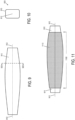
- FIG. 9 depicts another example of a braiding mandrel 910 around which one or more braided layers may be formed along at least a portion of a longitudinal axis 912 of the braiding mandrel.
- braiding mandrel 910 has a cross section that varies along longitudinal axis 912.
- Braiding mandrel 910 may be used to form composite articles that include a pair of structural ribs of an aeronautical vehicle, as an example.
- FIG. 11 depicts an example of a braided lay-up 1110 of one or more braided layers that may be formed around braiding mandrel 910.
- method 800 of FIG. 8 may be performed to obtain braided lay-up 1110.
- each braided layer may have a thread tow orientation that is biased at an angle relative to the tape tow orientation of that braided layer.
- each braided layer of braided lay-up 1110 may have a tape tow orientation that is biased at an angle relative to a tape tow orientation of neighboring braided layers.
- a second cover portion 1532 may be used to retain and compress preform 1522 onto consolidation mandrel 1510 during heating and consolidation.
- consolidation mandrel 1510 and/or cover portions 1530 and 1532 may take the form of one or more aluminum pressure bladders that are inflated to support the preforms during consolidation. It will be understood that a preform can be compressed during heating and consolidation using other suitable techniques.
- an increase in the displacement of the fibers during the consolidation process can be achieved by braiding with thermoplastic resin thread as compared to braiding with fiber-reinforced materials, thereby resulting in a greater reduction in undulation of the fibers within the consolidated form.
- compressing the preform following removal of the metallic thread can reduce undulation of fibers within the braided layers due to displacement of the fibers into regions previously occupied by the metallic thread.
- an increase in the displacement of the fibers during the consolidation process can be achieved by braiding with metallic thread that is removed prior to consolidation as compared to fiber-reinforced materials that remain within the consolidated form, thereby resulting in a greater reduction in undulation of the fibers within the consolidated form.
- a method of manufacturing a composite article comprising: forming one or more braided layers around a braiding mandrel along at least a portion of a longitudinal axis of the braiding mandrel by: for each braided layer, braiding tape segments of a fiber-reinforced thermoplastic resin tape applied at a tape tow orientation with thread segments applied at a thread tow orientation that is biased at an angle relative to the tape tow orientation.
- A.3. The method of clause A.1 or A.2, wherein the thread segments of each of the one or more braided layers include a metallic thread; and wherein the method further comprises: heating a preform that includes at least a portion of the one or more braided layers to obtain a consolidated form; and removing the metallic thread from the preform prior to consolidation of the preform to the consolidated form.
- A.6 The method of any one of the preceding clauses, wherein for a first braided layer of the one or more braided layers, the tape tow orientation is biased at an angle relative to the longitudinal axis of the braiding mandrel.
- A. 10 The method of any one of clauses A.7-A.9, wherein the plurality of braided layers includes a third braided layer; wherein the tape tow orientation of the third braided layer is biased at an angle relative to the tape tow orientation of the first braided layer and relative to the tape tow orientation of the second braided layer.
- a method of manufacturing a composite article comprising: forming a plurality of braided layers around a braiding mandrel along at least a portion of a longitudinal axis of the braiding mandrel by: for each braided layer of the plurality of braided layers, braiding tape segments of a fiber-reinforced thermoplastic resin tape applied at a tape tow orientation with thread segments of a thermoplastic resin thread applied at a thread tow orientation that is biased at an angle relative to the tape tow orientation; and heating and compressing a preform that includes at least a portion of the one or more braided layers to obtain a consolidated form; wherein the thermoplastic resin thread present in the preform is integrated into the consolidated form.
Landscapes
- Engineering & Computer Science (AREA)
- Textile Engineering (AREA)
- Mechanical Engineering (AREA)
- Chemical & Material Sciences (AREA)
- Composite Materials (AREA)
- Manufacturing & Machinery (AREA)
- Robotics (AREA)
- Braiding, Manufacturing Of Bobbin-Net Or Lace, And Manufacturing Of Nets By Knotting (AREA)
- Moulding By Coating Moulds (AREA)
Abstract
Description
- This application claims priority to
U.S. Provisional Patent Application No. 63/588,955, entitled THERMOPLASTIC BRAIDING FOR THE MANUFACTURE OF COMPOSITE ARTICLES, filed October 9, 2023 - The subject matter of the present disclosure relates generally to the manufacture of composite articles, and more specifically to braiding fiber-reinforced thermoplastic resin tape with thread.
- A variety of composite articles can be formed from thermoplastics. As an example, a thermoplastic resin can be reinforced with fibers to form a fiber-reinforced thermoplastic resin tape. Segments of the fiber-reinforced thermoplastic resin tape can be braided with each other to form a lay-up that is then heated to obtain a consolidated form of the braided tape segments. The consolidated form can be post-processed by cutting or shaping to obtain a final form of the composite article.
- An example method of manufacturing a composite article comprises forming one or more braided layers around a braiding mandrel. Each braided layer is formed by braiding tape segments of a fiber-reinforced thermoplastic resin tape applied at a tape tow orientation with thread segments applied at a thread tow orientation. For each braided layer, the thread tow orientation is biased at an angle relative to the tape tow orientation. Braiding of thread segments with fiber-reinforced thermoplastic resin tape segments at different tow orientations offers the potential to stabilize the tape segments within a braided layer while also addressing potential challenges associated with braiding of fiber-reinforced materials.
- In an example, the thread segments include a thermoplastic resin thread that is integrated into a consolidated form with the fiber-reinforced thermoplastic resin tape by application of heat. Braiding thermoplastic resin thread with fiber-reinforced thermoplastic resin tape offers the potential to provide a high rate of composite material placement without introducing significant bulk or mass as compared to braiding fiber-reinforced materials with each other. Integration of the thermoplastic resin thread into the consolidated form may reduce undulation of fibers of the fiber-reinforced thermoplastic resin tape that remain within the consolidated form. For example, integration of the thermoplastic resin thread into the surrounding resin matrix during consolidation may enable fibers of the fiber-reinforced thermoplastic resin tape to relax into a configuration that exhibits less undulation as compared to braiding with fiber-reinforced thermoplastic resin tape.
-
-
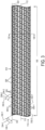
FIG. 1 depicts a segment of an example braiding mandrel having a longitudinal axis. -
FIG. 2 depicts the braiding mandrel ofFIG. 1 as viewed within a section that is orthogonal to the longitudinal axis. -
FIG. 3 depicts a first example of a braided layer that is formed around the braiding mandrel ofFIG. 1 along at least a portion of the longitudinal axis. -
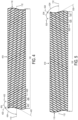
FIG. 4 depicts a second example of a braided layer that is formed around the braiding mandrel ofFIG. 1 along at least a portion of the longitudinal axis. -
FIG. 5 depicts a third example of a braided layer that is formed around the braiding mandrel ofFIG. 1 along at least a portion of the longitudinal axis. -
FIG. 6 depicts the braided layers ofFIGS. 3 ,4, and 5 being formed around the braiding mandrel ofFIG. 1 using braiding rings. -
FIG. 7 depicts the braided lay-up ofFIG. 6 formed circumferentially around the braiding mandrel ofFIG. 1 as viewed within a section. -
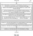
FIGS. 8A ,8B ,8C , and8D are flow diagrams depicting an example method of manufacturing a composite article. -
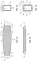
FIG. 9 depicts another example of a braiding mandrel having a longitudinal axis. -
FIG. 10 depicts the braiding mandrel ofFIG. 9 as viewed within a section that is orthogonal to the longitudinal axis. -
FIG. 11 depicts another example of a braided lay-up formed around a braiding mandrel along at least a portion of longitudinal axis of the braiding mandrel. -
FIG. 12 depicts an example in which the braided lay-up ofFIG. 11 is trimmed to form tab portions of a structural rib of an aeronautical vehicle. -
FIG. 13 depicts the braided lay-up ofFIG. 11 and the braiding mandrel ofFIG. 9 as viewed within a section that is orthogonal to the longitudinal axis. -
FIG. 14 depicts a first portion of the braided lay-up ofFIG. 11 removed from the braiding mandrel ofFIG. 9 . -
FIG. 15 depicts the first portion and a second portion of the braided lay-up ofFIG. 11 loaded onto a consolidation mandrel. - According to an example disclosed herein, a composite article may be formed using a braided lay-up that includes one or more braided layers. As an example, one or more braided layers may be formed circumferentially around a braiding mandrel along at least a portion of a longitudinal axis of the braiding mandrel. Each braided layer may include fiber-reinforced thermoplastic resin tape segments braided with thread segments. The fiber-reinforced thermoplastic resin tape segments of each braided layer may be applied at a respective tape tow orientation, and the thread segments of that braided layer may be applied at a thread tow orientation that differs from the tape tow orientation.
- The use of fibers to reinforce thermoplastic resin may facilitate the braiding process by increasing the strength and resiliency of the thermoplastic resin. Additionally, fiber reinforcement of thermoplastic resin may increase the strength and resiliency of the resulting composite article. However, potential disadvantages of braiding with fiber-reinforced thermoplastic resin tape or other fiber-reinforced resin materials can include introduction of bulk into the braided form and/or undulation of fibers that remain in the composite article following consolidation.
- As an example, braiding fiber-reinforced thermoplastic resin tape or other fiber-reinforced resin materials may introduce undulation to the fibers within the consolidated form. Undulation can occur in fiber-reinforced thermoplastic tape braiding as each segment of tape, along its length in the braid, alternately passes over, and then under, other tape segments in the braid. Accordingly, the reinforcing fibers within each tape segment can exhibit this undulation, especially in the case in which the reinforcing fibers run parallel to the length of the thermoplastic tape. This undulation is reduced, to some extent, when the braided form is debulked and the thermoplastic is consolidated, but is still present in the consolidated form as the fibers are prevented from relaxing into a non-undulated condition due to the "over-under" nature of the braid. The fiber undulation that remains in the consolidated form may adversely affect some of the material characteristics of the consolidated form, such as compared with a form in which the fibers do not undulate. Reducing fiber undulation, such as by incorporating thermoplastic resin into the braded form in accordance with the present disclosure, can improve the material characteristics of the form such as compared with a form in which fiber undulation is not reduced.
- As another example, braiding fiber-reinforced thermoplastic resin tape or other fiber-reinforced resin materials may introduce bulk into the braided form. This is generally attributable to the resiliency or stiffness of the tape segments that are braided together. The form must be debulked (generally, compressed) prior to consolidation. Reduction of bulk, for example by incorporating thermoplastic resin thread into the braided form (which is typically more pliable than fiber-reinforced thermoplastic resin tape), in accordance with the present disclosure, can simplify this pre-consolidation step. Braiding of thread segments with fiber-reinforced thermoplastic resin tape segments at different tow orientations offers the potential to stabilize the fiber-reinforced thermoplastic resin tape segments within a braided layer, and provide a high rate of composite material placement without adding significant bulk or mass as compared to braiding fiber-reinforced materials with each other.
- In a first example of the disclosed method, the thread segments include a thermoplastic resin thread. The thermoplastic resin thread may take the form of a single filament thread or a multi-filament thread, as examples. A preform that includes the fiber-reinforced thermoplastic resin tape and the thermoplastic resin thread of at least a portion of the one or more braided layers may be heated to obtain a consolidated form in which the thermoplastic resin thread is integrated into the consolidated form. For example, the thermoplastic resin thread may be integrated into the surrounding resin matrix of the consolidated form with resin of the fiber-reinforced thermoplastic resin tape.
- Integration of the thermoplastic resin thread into the consolidated form offers the potential to reduce undulation of fibers that remain from the fiber-reinforced thermoplastic resin tape within the consolidated form. As the thermoplastic resin thread is not reinforced with fibers, the thermoplastic resin thread can completely integrate into the resin matrix of the consolidated form. As an example, integration of the thermoplastic resin thread into the surrounding resin matrix during consolidation may enable fibers of the fiber-reinforced thermoplastic resin tape to relax into a configuration that exhibits less undulation as compared to braiding with fiber-reinforced thermoplastic resin tape. While unreinforced thermoplastic resin thread may offer less strength or resiliency as compared to fiber-reinforced materials, thermoplastic resin thread may offer a suitable alternative for braiding and stabilizing fiber-reinforced thermoplastic resin tape segments within a braided layer prior to consolidation.
- In a second example of the disclosed method, the thread segments include a metallic thread. The metallic thread may take the form of a single filament thread or a multi-filament thread, as examples. A preform that includes at least a portion of one or more braided layers may be heated to obtain a consolidated form. The metallic thread may be removed from the preform prior to consolidation to the consolidated form. Removal of the metallic thread from the preform prior to consolidation offers the potential to reduce undulation of fibers that remain from the fiber-reinforced thermoplastic resin tape within the consolidated form. As an example, removal of the metallic thread prior to consolidation may enable fibers of the fiber-reinforced thermoplastic resin tape to relax into a configuration that exhibits less undulation as compared to braiding with fiber-reinforced thermoplastic resin tape.
- In at least some examples, braiding of fiber-reinforced thermoplastic resin tape segments with thread segments to form a braided layer may be performed using a braiding ring. As an example, each braided layer may be formed using a respective braiding ring that applies the fiber-reinforced thermoplastic resin tape segments at a tape tow orientation and the thread segments at a thread tow orientation defined for the particular braided layer. As an example, a lay-up that includes three braided layers may be formed circumferentially around a braiding mandrel using three braiding rings.
- As further described herein, the fiber-reinforced thermoplastic resin tape segments of each braided layer may have a different tow orientation than the fiber-reinforced thermoplastic resin tape segments of other braided layers. Varying the tow orientation of the tape segments between or among the braided layers offers the potential to increase or vary the strength of the consolidated form.
- As an illustrative example, a first braided layer includes tape segments having a tape tow orientation of 0 degrees relative to the longitudinal axis of the braiding mandrel. A second braided layer includes tape segments having a tape tow orientation that is biased in a first angular direction (e.g., negative 60 degrees) relative to the longitudinal axis of the braiding mandrel. A third braided layer may include tape segments having a tape tow orientation that is biased in a second angular direction (e.g., positive 60 degrees) relative to the longitudinal axis of the braiding mandrel. At each braided layer, the thread segments that are braided with the tape segments of that braided layer may be biased at an angle relative to the tape segments to stabilize the tape segments for consolidation.
-
FIG. 1 depicts asegment 100 of anexample braiding mandrel 110 having alongitudinal axis 112. For illustrative purposes,braiding mandrel 110 takes the form of a cylinder in this example. It will be understood that a braiding mandrel can take other suitable forms, such as described in further detail with reference toFIGS. 9 and 10 , as additional examples. -
FIG. 2 depictsbraiding mandrel 110 as viewed within asection 120 that is orthogonal tolongitudinal axis 112. In this example,braiding mandrel 110 has a circular cross section corresponding to a cross section of a cylinder. -
FIG. 3 depicts a first example of abraided layer 310 formed aroundbraiding mandrel 110 along at least a portion oflongitudinal axis 112 of the braiding mandrel corresponding tosegment 100.Braided layer 310 is formed by braidingtape segments 320 of a fiber-reinforced thermoplastic resin tape applied at atape tow orientation 322 with thread segments (e.g., 330-1, 330-2) applied at a thread tow orientation (e.g., 332-1, 332-2). - In the example of
braided layer 310, a first subset of thread segments 330-1 is applied at thread tow orientation 332-1 that is biased at angle 334-1 in a first angular direction 336-1 relative to tapetow orientation 322. For example, the first subset of thread segments 330-1 may cross over and undertape segments 320 according to a braiding pattern that stabilizes the tape segments withinbraided layer 310. Example braiding patterns may feature the first subset of thread segments 330-1 crossing over one or more oftape segments 320, and then under one or more oftape segments 320 in a repeating pattern throughoutbraided layer 310. - Additionally, in the example of
braided layer 310, a second subset of thread segments 330-2 is applied at thread tow orientation 332-2 that is biased at angle 334-2 in a second angular direction 336-2 relative to tapetow orientation 322. For example, the second subset of thread segments 330-2 may cross over and undertape segments 320 according to a braiding pattern that further stabilizes the tape segments withinbraided layer 310. Example braiding patterns may feature the second subset of thread segments 330-2 crossing over one or more oftape segments 320, and then under one or more oftape segments 320 in a repeating pattern throughoutbraided layer 310. - As an illustrative example,
tape tow orientation 322 is parallel tolongitudinal axis 112, angle 334-1 of thread tow orientation 332-1 is -60 degrees relative totape tow orientation 322, and angle 334-2 of thread tow orientation 332-2 is +60 degrees relative totape tow orientation 322. It will be understood that other suitable thread tow orientations may be used that are biased at an angle relative to the tape tow orientation. - As described above,
tape tow orientation 322 oftape segments 320 ofbraided layer 310 is parallel tolongitudinal axis 112, which may be referred to as an axial configuration of tape segments. As described in further detail with reference toFIGS. 4 and 5 , other examples of braided layers may include tape segments that are applied at a tape tow orientation that is biased at an angle relative tolongitudinal axis 112, which may be referred to as a biaxial configuration. -
FIG. 4 depicts a second example of abraided layer 410 formed aroundbraiding mandrel 110 along at least a portion oflongitudinal axis 112 of the braiding mandrel corresponding tosegment 100. In this example, braidedlayer 410 is formed by braidingtape segments 420 of a fiber-reinforced thermoplastic resin tape applied at atape tow orientation 422 withthread segments 430 applied at athread tow orientation 432 that is biased at anangle 434 relative to the tape tow orientation. Furthermore, in this example,tape tow orientation 422 is biased at anangle 424 relative tolongitudinal axis 112, which refers to a biaxial configuration oftape segments 420. - As an illustrative example,
angle 424 oftape tow orientation 422 is -60 degrees relative tolongitudinal axis 112, andangle 434 ofthread tow orientation 432 is -60 degrees relative totape tow orientation 422. In this example,thread tow orientation 432 may be described as being biased at an angle of +60 degrees relative tolongitudinal axis 112. It will be understood that other suitable tape tow orientations and thread tow orientations may be used. -
Thread segments 430 may cross over and undertape segments 420 according to a braiding pattern that stabilizes the tape segments withinbraided layer 410. Example braiding patterns may featurethread segments 430 crossing over one or more oftape segments 420, and then under one or more oftape segments 420 in a repeating pattern throughoutbraided layer 410. -
FIG. 5 depicts a third example of abraided layer 510 formed aroundbraiding mandrel 110 along at least a portion oflongitudinal axis 112 of the braiding mandrel corresponding tosegment 100. In this example, braidedlayer 510 is formed by braidingtape segments 520 of a fiber-reinforced thermoplastic resin tape applied at atape tow orientation 522 withthread segments 530 applied at athread tow orientation 532 that is biased at anangle 534 relative to the tape tow orientation. Furthermore, in this example,tape tow orientation 522 is biased at anangle 524 relative tolongitudinal axis 112, which refers to a biaxial configuration oftape segments 520. - As an illustrative example,
angle 524 oftape tow orientation 522 is +60 degrees relative tolongitudinal axis 112, andangle 534 ofthread tow orientation 532 is +60 degrees relative totape tow orientation 522. In this example,thread tow orientation 532 may be described as being biased at an angle of -60 degrees relative tolongitudinal axis 112. It will be understood that other suitable tape tow orientations and thread tow orientations may be used. -
Thread segments 530 may cross over and undertape segments 520 according to a braiding pattern that stabilizes the tape segments withinbraided layer 510. Example braiding patterns may featurethread segments 530 crossing over one or more oftape segments 520, and then under one or more oftape segments 520 in a repeating pattern throughoutbraided layer 510. -
FIG. 6 depicts an example of a braided lay-up 600 that includes a plurality of braided layers that are shown schematically to be in the process of being formed circumferentially aroundbraiding mandrel 100 along at least a portion oflongitudinal axis 112. In the example ofFIG. 6 , braided lay-up 600 includes braidedlayer 310 ofFIG. 3 as a first layer formed circumferentially aroundbraiding mandrel 110 using afirst braiding ring 610.First braiding ring 610 may be sized to accommodatebraiding mandrel 110 and any braided layers previously applied to the braiding mandrel within an interior region defined by the braiding ring. - Braided lay-
up 600 further includes braidedlayer 410 ofFIG. 4 as a second layer formed circumferentially aroundbraiding mandrel 110 and braidedlayer 310 using asecond braiding ring 612.Second braiding ring 612 may be sized to accommodatebraiding mandrel 110 and any braided layers (e.g., 310) previously applied to the braiding mandrel within an interior region defined by the braiding ring. - Braided lay-
up 600 further includes braidedlayer 510 ofFIG. 5 as a third layer formed circumferentially aroundbraiding mandrel 110, braidedlayer 310, and braidedlayer 410 using athird braiding ring 614.Third braiding ring 614 may be sized to accommodatebraiding mandrel 110 and any braided layers (e.g., 310 and 410) previously applied to the braiding mandrel within an interior region defined by the braiding ring. -
Braiding mandrel 110 may be moved relative to braiding rings 610, 612, and 614 throughout the braiding process, as depicted schematically inFIG. 6 byarrow 620. - It will be understood that the configuration of braiding rings 610, 612, and 614 as shown in
FIG. 6 is merely representative, and is shown schematically for the purposes of explanation. As an example, braiding rings 612 and 614 inFIG. 6 are shown to be in the process of dispensing two braiding materials in biaxial configurations, whereasbraiding ring 610 is shown to be dispensing a number of axial tape segments and opposing biaxial thread segments. However, braiding rings may be configured as desired, such as with any number of individual spools (not shown) of braiding material, such as tape, thread, and so forth, which can be stationary and/or configured to travel around the ring in either or both directions at desired speeds as the braiding ring moves relative to the mandrel, for example, to dispense segments of material at desired angles or orientations relative to the ring and/or mandrel. In practice, any number and/or configuration of braiding rings may be used. - It will also be understood that a braided lay-up, such as example braided lay-up 600 of
FIG. 6 may include any suitable quantity and configuration of braided layers. In the example of braided lay-up 600, braided layers that neighbor each other have different tape tow orientations relative tolongitudinal axis 112, and are biased at an angle relative to each other. For example,tape tow orientation 322 ofbraided layer 310 may be parallel tolongitudinal axis 112, as described with reference toFIG. 3 .Tape tow orientation 422 ofbraided layer 410 may be biased at an angle (e.g., -60 degrees) in a first angular direction relative tolongitudinal axis 112, and therefore biased at an angle relative to tapetow orientation 322 ofbraided layer 310. As another example,tape tow orientation 522 ofbraided layer 510 may be biased at an angle (e.g., +60 degrees) in a second angular direction relative tolongitudinal axis 112, and therefore biased at an angle relative to tapetow orientation 422 ofbraided layer 410. As previously described, the use of varying tape tow orientations among braided layers may be used to increase or vary the strength of a braided lay-up. -
FIG. 7 depicts braided lay-up 600 formed circumferentially aroundbraiding mandrel 110 as viewed withinsection 120 shown inFIG. 6 . In this example, braidedlayer 310 ofFIG. 3 forms a first braided layer of braided lay-up 600, braidedlayer 410 ofFIG. 4 forms a second braided layer of the braided lay-up, and braidedlayer 510 ofFIG. 5 forms a third braided layer of the braided lay-up. As previously described, a braided lay-up may include any suitable quantity and configuration of braided layers. -
FIGS. 8A ,8B ,8C , and8D are flow diagrams depicting anexample method 800 of manufacturing a composite article. The composite article may be formed using a braided lay-up that includes one or more braided layers. WithinFIGS. 8A ,8B , and8C , a plurality of braided layers may be formed circumferentially around a braiding mandrel along at least a portion of a longitudinal axis of the braiding mandrel, as depicted atoperation 802. As part ofoperation 802, each braided layer may be formed by braiding tape segments of a fiber-reinforced thermoplastic resin tape applied at a tape tow orientation with thread segments applied at a thread tow orientation that is biased at an angle relative to the tape tow orientation. Furthermore, in at least some examples, neighboring braided layers of the braided lay-up may have different tape tow orientations relative to each other, such as previously described with reference toFIG. 6 . - Referring to
FIG. 8A , at 810, the method includes forming a first braided layer around the braiding mandrel along at least the portion of the longitudinal axis of the braiding mandrel. As an example, the first braided layer may include one ofbraided layer 310 ofFIG. 3 ,braided layer 410 ofFIG. 4 , orbraided layer 510 ofFIG. 5 . As previously described with reference toFIG. 6 , the first braided layer may include braidedlayer 310 ofFIG. 3 in which the tape tow orientation is parallel to the longitudinal axis of the braiding mandrel. In at least some examples, the tape tow orientation being parallel to the longitudinal axis of the braiding mandrel may provide a suitable base for the braided lay-up upon which additional braided layers may be formed. However, it will be understood that a tape tow orientation that is biased at an angle relative to the longitudinal axis of the braiding mandrel may be used for the first braided layer in other examples. - As depicted at 812, the tape tow orientation of the tape segments of the first braided layer has a first angular orientation relative to the longitudinal axis of the braiding mandrel. As described with reference to
braided layer 310 ofFIG. 3 , the tape tow orientation may be parallel to the longitudinal axis of the braiding mandrel. As described with reference to braidedlayers FIGS. 4 and 5 , the tape tow orientation may be biased at an angle relative to the longitudinal axis of the braiding mandrel. - As depicted at 814, the thread tow orientation of the thread segments of the first braided layer may be biased at an angle relative to the tape tow orientation of the tape segments of the first braided layer.
- As part of forming the first braided layer at 810, the method at 816 includes braiding the tape segments of the fiber-reinforced thermoplastic resin tape applied at the tape tow orientation with the thread segments applied at the thread tow orientation. As an example, the tape segments may be braided with the thread segments using a first braiding ring, as previously described with reference to
FIG. 6 . - The thread segments of the first braided layer may take various forms. As a first example, the thread segments of the first braided layer include a
thermoplastic resin thread 818. As a second example, the thread segments of the first braided layer include ametallic thread 820. - At 822, the method may include securing one or more of the thread segments to one or more of the tape segments of the first braided layer to further stabilize the first braided layer. As an example, thread segments may be secured to tape segments by tack welding, which may include selectively applying heat to locations of the first braided layer where thread segments are to be secured to tape segments.
- At 824, the method may include securing one or more pad-ups to the first braided layer. Pad-ups may be used to define and add reinforcement structure to a braided lay-up. A pad-up may take the form of a fiber-reinforced resin pad, as an example. Each pad-up may be secured to the first braided layer by tack welding the pad-up to one or more locations of the first braided layer, such as to portions of one or more thread segments and/or tape segments.
- Referring to
FIG. 8B , at 830, the method includes forming a second braided layer around the first braided layer and the braiding mandrel along at least the portion of the longitudinal axis of the braiding mandrel. As an example, the first braided layer may include another one ofbraided layer 310 ofFIG. 3 ,braided layer 410 ofFIG. 4 , orbraided layer 510 ofFIG. 5 to provide a different tape tow orientation relative to the first braided layer. - As depicted at 832, the tape tow orientation of the tape segments of the second braided layer has a second angular orientation relative to the longitudinal axis of the braiding mandrel. As described with reference to
braided layer 310 ofFIG. 3 , the tape tow orientation of the second braided layer may be parallel to the longitudinal axis of the braiding mandrel. As described with reference to braidedlayers FIGS. 4 and 5 , the tape tow orientation of the second braided layer may be biased at an angle relative to the longitudinal axis of the braiding mandrel. - As depicted at 834, the thread tow orientation of the thread segments of the second braided layer may be biased at an angle relative to the tape tow orientation of the tape segments of the second braided layer.
- As part of forming the second braided layer at 830, the method at 836 includes braiding the tape segments of the fiber-reinforced thermoplastic resin tape applied at the tape tow orientation with the thread segments applied at the thread tow orientation. As an example, the tape segments may be braided with the thread segments using a second braiding ring, as previously described with reference to
FIG. 6 . - The thread segments of the second braided layer may take various forms. As a first example, the thread segments of the second braided layer include a
thermoplastic resin thread 838. As a second example, the thread segments of the second braided layer include ametallic thread 840. - At 842, the method may include securing one or more of the thread segments to one or more of the tape segments of the second braided layer to further stabilize the second braided layer. As an example, thread segments may be secured to tape segments by tack welding.
- At 844, the method may include securing the second braided layer to the first braided layer to further stabilize the braided lay-up. As an example, thread segments and/or tape segments of the second braided layer may be secured to thread segments and/or tape segments of the first braided layer by tack welding.
- At 846, the method may include securing one or more pad-ups to the second braided layer. As previously described, pad-ups may be used to define and add reinforcement structure to a braided lay-up. Each pad-up may be secured to the second braided layer by tack welding the pad-up to one or more locations of the second braided layer, such as to portions of one or more thread segments and/or tape segments.
- Referring to
FIG. 8C , at 850, the method includes forming a third braided layer around the braided layer, the second braided layer, and the braiding mandrel along at least the portion of the longitudinal axis of the braiding mandrel. As an example, the third braided layer may include another one ofbraided layer 310 ofFIG. 3 ,braided layer 410 ofFIG. 4 , orbraided layer 510 ofFIG. 5 to provide a different tape tow orientation relative to some or all of the preceding layers, including the second braided layer and the first braided layer. - As depicted at 852, the tape tow orientation of the tape segments of the third braided layer has a third angular orientation relative to the longitudinal axis of the braiding mandrel. As described with reference to
braided layer 310 ofFIG. 3 , the tape tow orientation of the third braided layer may be parallel to the longitudinal axis of the braiding mandrel. As described with reference to braidedlayers FIGS. 4 and 5 , the tape tow orientation of the third braided layer may be biased at an angle relative to the longitudinal axis of the braiding mandrel. - As depicted at 854, the thread tow orientation of the thread segments of the second braided layer may be biased at an angle relative to the tape tow orientation of the tape segments of the third braided layer.
- As part of forming the third braided layer at 850, the method at 856 includes braiding the tape segments of the fiber-reinforced thermoplastic resin tape applied at the tape tow orientation with the thread segments applied at the thread tow orientation. As an example, the tape segments may be braided with the thread segments using a third braiding ring, as previously described with reference to
FIG. 6 . - The thread segments of the third braided layer may take various forms. As a first example, the thread segments of the third braided layer include a
thermoplastic resin thread 858. As a second example, the thread segments of the third braided layer include ametallic thread 860. - At 862, the method may include securing one or more of the thread segments to one or more of the tape segments of the third braided layer to further stabilize the third braided layer. As an example, thread segments may be secured to tape segments by tack welding.
- At 844, the method may include securing the third braided layer to the second braided layer to further stabilize the braided lay-up. As an example, thread segments and/or tape segments of the third braided layer may be secured to thread segments and/or tape segments of the second braided layer by tack welding.
- At 846, the method may include securing one or more pad-ups to the third braided layer. As previously described, pad-ups may be used to define and add reinforcement structure to a braided lay-up. Each pad-up may be secured to the third braided layer by tack welding the pad-up to one or more locations of the third braided layer, such as to portions of one or more thread segments and/or tape segments.
- In some examples, a braided lay-up formed by
method 800 may include four or more braided layers. In this example, portions ofmethod 800 used to form the first braided layer, the second braided layer, and/or the third braided layer may be repeated one or more additional times to add one or more additional braided layers to the braided lay-up. For example, another instance of the first braided layer formed at 810 or the second braided layer formed at 830 may be formed around the third braided layer. As each additional braided layer is formed around a preceding braided layer, the additional braided layer may have a tape tow orientation that differs from the preceding braided layer. This configuration provides for tape segments at successive braided layers that are angled relative to each other, thereby varying strength and/or increasing stability of the braided lay-up. - Referring to
FIG. 8D , at 868, the method includes processing the braided lay-up to obtain one or more preforms for consolidation. As part of processing performed at 868, the method at 870 may include performing one or more of operations 870 - 880. - At 870, the method may include trimming the braided lay-up to obtain a desired form. An example of trimming a braided lay-up is described in further detail with reference to
FIG. 12 . - At 872, the method may include cutting the braided lay-up into two or more portions. In at least some examples, the braided lay-up may be cut into two or more portions to enable the braided lay-up to be removed from the braiding mandrel. An example of cutting a braided lay-up is described in further detail with reference to
FIG. 13 . - At 874, the method may include removing the braided lay-up or portions thereof from the braiding mandrel. Removal of the braided lay-up or portions thereof from the braiding mandrel can enable further processing of the braided lay-up or portions thereof, such as for consolidation on a consolidation mandrel. However, in some examples, the braiding mandrel may also be used as a consolidation mandrel. In these examples,
operation 874 may be omitted. Furthermore, in some examples, the braiding mandrel may take the form of a collapsible braiding mandrel that is inflated to provide support for the braided lay-up during formation of the various braided layers. In these example, cutting of the braided lay-up at 872 may be omitted, as the collapsible braiding mandrel may be removed from the braided lay-up without cutting of the braided lay-up. - At 876, the method may include forming and securing any accessory structures from features of the braided lay-up. An example of forming and security accessory structures is described in further detail with reference to
FIG. 14 . - At 878, the method may include loading the braided lay-up or portions thereof onto a consolidation mandrel. An example consolidation mandrel is described in further detail with reference to
FIG. 15 . - Following processing performed at
operation 868, the one or more preforms obtained from the braided lay-up or portions are ready for consolidation. - At 884, the method includes heating and compressing the one or more preforms to obtain one or more
consolidated forms 886. Any suitable technique for heating and compressing the preforms may be used to obtain the consolidated forms. As an example, induction heating may be used to heat the preforms that are compressed onto the consolidation mandrel by one or more inflatable bladders. Compressing the preform during heating and consolidation can reduce the bulk of the preform and resulting consolidated form by decreasing or eliminating volumetric regions of free air space or voids within individual braided layers and/or between the braided layers. - Heat applied to the one or more preforms causes thermoplastic resin of the fiber-reinforced thermoplastic resin tape and the thermoplastic resin thread (if used for braiding) of each braided layer to integrate into a resin matrix of the consolidated form. In the case of thermoplastic resin thread being used in one or more of the braided layers, fibers of the fiber-reinforced thermoplastic resin tape of those braided layers may relax during the heating process, thereby potentially reducing undulation of the fibers.
- In examples where one or more thread segments of the braided lay-up include a metallic thread, the method at 888 may include removing the one or more thread segments that include the metallic thread while heating is performed at 884, but prior to compressing and consolidating the preforms to the consolidated forms. As an example, metallic thread segments may be removed from the one or more preforms by pulling the metallic thread segments from the preform as the preform is heated. Following removal of the metallic thread segments, the preform can be compressed to obtain the consolidated form. Heating of the preforms may serve to melt or soften resin contained in the preforms to facilitate removal of the metallic thread segments. In another example, the metallic thread segments may be removed from the preforms prior to heating. Removal of the metallic thread segments prior to consolidation may enable fibers of the fiber-reinforced thermoplastic resign tape to relax during the heating process, thereby potentially reducing undulation of the fibers in the consolidated form.
- At 890, the method includes removing the one or more consolidated forms from the consolidation mandrel. At 892, the method includes performing post-processing of the one or more consolidated forms. As an example, the consolidated forms may be trimmed, cut, sanded, painted, etc. to obtain a final form of one or more
composite articles 894. - The thermoplastic materials described herein, including the fiber-reinforced thermoplastic resin tape, thermoplastic resin thread, and thermoplastic resin pad-ups may include polyaryletherketone (PAEK) thermoplastics, such as polyether ether ketone (PEEK) and/or polyetherketoneketone (PEKK), polyphenylene sulfide (PPS), and/or polyetherimide (PEI), as examples. Fiber contained within the fiber-reinforced thermoplastic resin tape and thermoplastic resin pad-ups may include graphite fibers, as an example. As an example, the fiber-reinforced thermoplastic resin tape described herein may take the form of a thermoplastic slit tape in which fibers are pre-impregnated with thermoplastic resin. Other suitable types of thermoplastic resins and/or reinforcement fibers may be used.
-
FIG. 9 depicts another example of abraiding mandrel 910 around which one or more braided layers may be formed along at least a portion of alongitudinal axis 912 of the braiding mandrel. In contrast tobraiding mandrel 110 ofFIG. 1 ,braiding mandrel 910 has a cross section that varies alonglongitudinal axis 912.Braiding mandrel 910 may be used to form composite articles that include a pair of structural ribs of an aeronautical vehicle, as an example. -
FIG. 10 depictsbraiding mandrel 910 ofFIG. 9 as viewed within asection 920 that is orthogonal tolongitudinal axis 912. In this example,braiding mandrel 910 is a closed form that approximates a rectangular shape when viewed withinsection 920. -
FIG. 11 depicts an example of a braided lay-up 1110 of one or more braided layers that may be formed aroundbraiding mandrel 910. As an example,method 800 ofFIG. 8 may be performed to obtain braided lay-up 1110. In the example of braided lay-up 1110, each braided layer may have a thread tow orientation that is biased at an angle relative to the tape tow orientation of that braided layer. Additionally, in at least some examples, each braided layer of braided lay-up 1110 may have a tape tow orientation that is biased at an angle relative to a tape tow orientation of neighboring braided layers. -
FIG. 12 depicts an example in which braided lay-up 1110 ofFIG. 11 is trimmed at 1210 and 1212 to form afirst tab portion 1214, and is trimmed at 1220 and 1222 to form asecond tab portion 1224. In this example,first tab portion 1214 andsecond tab portion 1224 are located on opposing ends of braided lay-up 1110, as orientated alonglongitudinal axis 912. -
FIG. 13 depicts braided lay-up 1110 andbraiding mandrel 910 as viewed withinsection 920 that is orthogonal tolongitudinal axis 912. In this example, braided lay-up 1110 is cut into afirst portion 1310 and asecond portion 1312 along a path indicated byarrows 1320.First portion 1310 of braided lay-up 1110 is also identified inFIG. 12 for reference. As previously described, cutting a braided lay-up into two or more portions enables the braided lay-up or portions thereof to be removed from the braiding mandrel. Additionally, the two or more portions of the braided lay-up may form respective composite articles, such as a pair of structural ribs for an aeronautical vehicle, as an example. In this example, a right structural rib for a right side of the aeronautical vehicle and a left structural rib for a left side of the aeronautical vehicle may be formed on a common braiding mandrel. -
FIG. 14 depictsfirst portion 1310 of braided lay-up 1110 removed from braidingmandrel 910. Aside view 1230 offirst portion 1310 identified by an arrow inFIG. 12 is depicted inFIG. 14 . In this example, accessory structures that includeflanges tab portions up 1110. As an example,tab portion 1214 may be folded or bent at room temperature into a shape represented schematically inFIG. 14 byflange 1410.Flange 1410 may be secured by tack welding two or more braided layers of braided lay-up 1110 to retain the shape shown inFIG. 14 for subsequent consolidation. Similarly,flange 1420 may be secured by tack welding two or more braided layers of braided lay-up 1110 to retain the shape shown inFIG. 14 for subsequent consolidation.Second portion 1312 may be similarly processed to form and secure any accessory structures from features of the braided lay-up.
FIG. 15 depictsfirst portion 1310 andsecond portion 1312 loaded onto aconsolidation mandrel 1510, as viewed withinsection 920. In this example,first portion 1310 refers to afirst preform 1520, andsecond portion 1312 refers to asecond preform 1522. Afirst cover portion 1530 may be used to retain and compressfirst preform 1520 ontoconsolidation mandrel 1510 during heating and consolidation. Similarly, asecond cover portion 1532 may be used to retain and compresspreform 1522 ontoconsolidation mandrel 1510 during heating and consolidation. In at least some examples,consolidation mandrel 1510 and/orcover portions - As previously described, compressing a preform during heating and consolidation can reduce the bulk of the preform and resulting consolidated form by decreasing or eliminating volumetric regions of free air space or voids within individual braided layers and/or between the braided layers. In the disclosed examples where braided layers of a preform include thermoplastic resin thread braided with fiber-reinforced thermoplastic resin tape, compressing the preform can reduce undulation of fibers within the braided layers due to displacement of resin contained in the thread. This displacement of resin enables segments of the fibers overlapping the thread within the braid to displace into regions previously occupied by the thread. In such examples, an increase in the displacement of the fibers during the consolidation process can be achieved by braiding with thermoplastic resin thread as compared to braiding with fiber-reinforced materials, thereby resulting in a greater reduction in undulation of the fibers within the consolidated form.
- In the disclosed examples where braided layers of a preform are formed by metallic thread braided with fiber-reinforced thermoplastic resin tape, compressing the preform following removal of the metallic thread can reduce undulation of fibers within the braided layers due to displacement of the fibers into regions previously occupied by the metallic thread. In such examples, an increase in the displacement of the fibers during the consolidation process can be achieved by braiding with metallic thread that is removed prior to consolidation as compared to fiber-reinforced materials that remain within the consolidated form, thereby resulting in a greater reduction in undulation of the fibers within the consolidated form.
- Further, the disclosure comprises configurations and approaches according to the following clauses.
- A.1. A method of manufacturing a composite article, the method comprising: forming one or more braided layers around a braiding mandrel along at least a portion of a longitudinal axis of the braiding mandrel by: for each braided layer, braiding tape segments of a fiber-reinforced thermoplastic resin tape applied at a tape tow orientation with thread segments applied at a thread tow orientation that is biased at an angle relative to the tape tow orientation.
- A.2. The method of clause A. 1, wherein the thread segments of each of the one or more braided layers include a thermoplastic resin thread; wherein the method further comprises heating a preform that includes at least a portion of the one or more braided layers to obtain a consolidated form; and wherein the thermoplastic resin thread present in the preform is integrated into the consolidated form.
- A.3. The method of clause A.1 or A.2, wherein the thread segments of each of the one or more braided layers include a metallic thread; and wherein the method further comprises: heating a preform that includes at least a portion of the one or more braided layers to obtain a consolidated form; and removing the metallic thread from the preform prior to consolidation of the preform to the consolidated form.
- A.4. The method of any one of the preceding clauses, wherein for a first braided layer of the one or more braided layers, the tape tow orientation is parallel to the longitudinal axis of the braiding mandrel.
- A.5. The method of clause A.4, wherein for the first braided layer: the thread tow orientation of a first subset of the thread segments is biased in a first angular direction relative to the tape tow orientation; and the thread tow orientation of a second subset of the thread segments is biased in a second angular direction relative to the tape tow orientation that is opposite the first angular direction.
- A.6. The method of any one of the preceding clauses, wherein for a first braided layer of the one or more braided layers, the tape tow orientation is biased at an angle relative to the longitudinal axis of the braiding mandrel.
- A.7. The method of any one of the preceding clauses, wherein the one or more braided layers include a plurality of braided layers; wherein the tape tow orientation of a first braided layer of the plurality of braided layers is biased at an angle relative to the tape tow orientation of a second braided layer of the plurality of braided layers.
- A.8. The method of clause A.7, further comprising: tack welding second braided layer to the first braided layer.
- A.9. The method of clause A.7, further comprising: heating a preform that includes at least a portion of the first braided layer and the second braided layer to obtain a consolidated form.
- A. 10. The method of any one of clauses A.7-A.9, wherein the plurality of braided layers includes a third braided layer; wherein the tape tow orientation of the third braided layer is biased at an angle relative to the tape tow orientation of the first braided layer and relative to the tape tow orientation of the second braided layer.
- B. 1. A method of manufacturing a composite article, the method comprising: forming a plurality of braided layers around a braiding mandrel along at least a portion of a longitudinal axis of the braiding mandrel by: for each braided layer of the plurality of braided layers, braiding tape segments of a fiber-reinforced thermoplastic resin tape applied at a tape tow orientation with thread segments of a thermoplastic resin thread applied at a thread tow orientation that is biased at an angle relative to the tape tow orientation; and heating and compressing a preform that includes at least a portion of the one or more braided layers to obtain a consolidated form; wherein the thermoplastic resin thread present in the preform is integrated into the consolidated form.
- B.2. The method of clause B. 1, wherein the tape tow orientation of a first braided layer of the plurality of braided layers is biased at an angle relative to the tape tow orientation of a second braided layer of the plurality of braided layers.
- B.3. The method of clause B.2, wherein the tape tow orientation of the first braided layer is parallel to the longitudinal axis of the braiding mandrel; and
wherein the tape tow orientation of the second braided layer is biased at an angle relative to the longitudinal axis of the braiding mandrel. - B.4. The method of any one of clauses B. 1- B.3, wherein the tape tow angle of a third braided layer of the plurality of braided layers is biased at an angle relative to the longitudinal axis of the braiding mandrel in an opposite angular direction as the tape tow angle of the second braided layer.
- C.1. A method of manufacturing a composite article, the method comprising: forming a plurality of braided layers around a braiding mandrel along at least a portion of a longitudinal axis of the braiding mandrel by: for each braided layer of the plurality of braided layers, braiding tape segments of a fiber-reinforced thermoplastic resin tape applied at a tape tow orientation with thread segments of a thermoplastic resin thread applied at a thread tow orientation that is biased at an angle relative to the tape tow orientation; tack welding a braided layer of the plurality of braided layers to another braided layer of the plurality of braided layers to stabilize the braided lay-up; cutting the braided lay-up into two or more portions; and heating and compressing a preform that includes a portion of the braided lay-up to obtain a consolidated form; wherein the thermoplastic resin thread present in the preform is integrated into the consolidated form.
- C.2. The method of clause C.1, wherein the composite article takes the form of a structural rib of an aeronautical vehicle.
- C.3. The method of clause C.1 or C.2, further comprising: heating another preform that includes another portion of the braided lay-up on the consolidation mandrel.
- C.4. The method of any one ofbclauses C.1-C.3, wherein the tape tow orientation of a first braided layer of the plurality of braided layers is biased at an angle relative to the tape tow orientation of a second braided layer of the plurality of braided layers.
- C.5. The method of clause C.4, wherein the tape tow orientation of a third braided layer of the plurality of braided layers is biased at an angle relative to the tape tow orientation of the second braided layer of the plurality of braided layers.
- C.6. The method of clause C.5, wherein the tape tow orientation of the third braided layer is biased at an angle relative to the tape tow orientation of the first braided layer.
- It will be understood that the configurations and/or approaches described herein are exemplary in nature, and that these specific examples are not to be considered in a limiting sense, because numerous variations are possible. The specific methods and operations described herein may represent one or more of any number of processing techniques. As such, various acts illustrated and/or described may be performed in the sequence illustrated and/or described, in other sequences, in parallel, or omitted. Likewise, the order of the above-described processes may be changed.
- The subject matter of the present disclosure includes all novel and non-obvious combinations and sub-combinations of the various configurations, approaches, methods, operations, and other features, functions, acts, and/or properties disclosed herein, as well as any and all equivalents thereof.
Claims (15)
- A method of manufacturing a composite article, the method comprising:
forming one or more braided layers around a braiding mandrel along at least a portion of a longitudinal axis of the braiding mandrel by:
for each braided layer, braiding tape segments of a fiber-reinforced thermoplastic resin tape applied at a tape tow orientation with thread segments applied at a thread tow orientation that is biased at an angle relative to the tape tow orientation. - The method of claim 1, wherein the thread segments of each of the one or more braided layers include a thermoplastic resin thread;wherein the method further comprises heating a preform that includes at least a portion of the one or more braided layers to obtain a consolidated form; andwherein the thermoplastic resin thread present in the preform is integrated into the consolidated form.
- The method of claim 1, wherein the thread segments of each of the one or more braided layers include a metallic thread; and
wherein the method further comprises:heating a preform that includes at least a portion of the one or more braided layers to obtain a consolidated form; andremoving the metallic thread from the preform prior to consolidation of the preform to the consolidated form. - The method of any one of the preceding claims, wherein for a first braided layer of the one or more braided layers, the tape tow orientation is parallel to the longitudinal axis of the braiding mandrel.
- The method of claim 4, wherein for the first braided layer:the thread tow orientation of a first subset of the thread segments is biased in a first angular direction relative to the tape tow orientation; andthe thread tow orientation of a second subset of the thread segments is biased in a second angular direction relative to the tape tow orientation that is opposite the first angular direction.
- The method of claim 1, wherein for a first braided layer of the one or more braided layers, the tape tow orientation is biased at an angle relative to the longitudinal axis of the braiding mandrel.
- The method of any one of the preceding claims, wherein the one or more braided layers include a plurality of braided layers;
wherein the tape tow orientation of a first braided layer of the plurality of braided layers is biased at an angle relative to the tape tow orientation of a second braided layer of the plurality of braided layers. - The method of claim 7, further comprising:
tack welding second braided layer to the first braided layer; or optionally further comprising:heating a preform that includes at least a portion of the first braided layer and the second braided layer to obtain a consolidated form; or optionally wherein the plurality of braided layers includes a third braided layer;wherein the tape tow orientation of the third braided layer is biased at an angle relative to the tape tow orientation of the first braided layer and relative to the tape tow orientation of the second braided layer. - The method of claim 1, wherein the thread segments are of a thermoplastic resin thread applied at the thread tow orientation that is biased at the angle relative to the tape tow orientation; the method further comprising:heating and compressing a preform that includes at least a portion of the one or more braided layers to obtain a consolidated form;wherein the thermoplastic resin thread present in the preform is integrated into the consolidated form.
- The method of claim 9, wherein the tape tow orientation of a first braided layer of the plurality of braided layers is biased at an angle relative to the tape tow orientation of a second braided layer of the plurality of braided layers.
- The method of claim 10, wherein the tape tow orientation of the first braided layer is parallel to the longitudinal axis of the braiding mandrel; and
wherein the tape tow orientation of the second braided layer is biased at an angle relative to the longitudinal axis of the braiding mandrel. - The method of claim 11, wherein the tape tow angle of a third braided layer of the plurality of braided layers is biased at an angle relative to the longitudinal axis of the braiding mandrel in an opposite angular direction as the tape tow angle of the second braided layer.
- The method of claim 1, wherein the thread segments are of a thermoplastic resin thread applied at the thread tow orientation that is biased at the angle relative to the tape tow orientation; the method further comprising:tack welding a braided layer of the plurality of braided layers to another braided layer of the plurality of braided layers to stabilize the braided lay-up;cutting the braided lay-up into two or more portions; andheating and compressing a preform that includes a portion of the braided lay-up to obtain a consolidated form;wherein the thermoplastic resin thread present in the preform is integrated into the consolidated form.
- The method of claim 13, wherein the composite article takes the form of a structural rib of an aeronautical vehicle; or optionally further comprising:
heating another preform that includes another portion of the braided lay-up on the consolidation mandrel. - The method of claim 13, wherein the tape tow orientation of a first braided layer of the plurality of braided layers is biased at an angle relative to the tape tow orientation of a second braided layer of the plurality of braided layers; and optionallywherein the tape tow orientation of a third braided layer of the plurality of braided layers is biased at an angle relative to the tape tow orientation of the second braided layer of the plurality of braided layers; and optionallywherein the tape tow orientation of the third braided layer is biased at an angle relative to the tape tow orientation of the first braided layer.
Applications Claiming Priority (2)
| Application Number | Priority Date | Filing Date | Title |
|---|---|---|---|
| US202363588955P | 2023-10-09 | 2023-10-09 | |
| US18/499,107 US20250115008A1 (en) | 2023-10-09 | 2023-10-31 | Thermoplastic braiding for the manufacture of composite articles |
Publications (2)
| Publication Number | Publication Date |
|---|---|
| EP4538009A1 true EP4538009A1 (en) | 2025-04-16 |
| EP4538009B1 EP4538009B1 (en) | 2026-02-11 |
Family
ID=92171924
Family Applications (1)
| Application Number | Title | Priority Date | Filing Date |
|---|---|---|---|
| EP24192064.4A Active EP4538009B1 (en) | 2023-10-09 | 2024-07-31 | Thermoplastic braiding for the manufacture of composite articles |
Country Status (3)
| Country | Link |
|---|---|
| US (1) | US20250115008A1 (en) |
| EP (1) | EP4538009B1 (en) |
| CN (1) | CN119795613A (en) |
Citations (4)
| Publication number | Priority date | Publication date | Assignee | Title |
|---|---|---|---|---|
| US20070193439A1 (en) * | 2004-04-06 | 2007-08-23 | Eads Deutschland Gmbh | Method For Producing Fiber Composite Semi-Finished Products By Means Of A Round Braiding Technique |
| US20160016355A1 (en) * | 2014-07-16 | 2016-01-21 | The Boeing Company | Adaptive Composite Structure Using Shape Memory Alloys |
| EP3040181A1 (en) * | 2015-01-05 | 2016-07-06 | The Boeing Company | Induction consolidation for wind blade fabrication |
| US20200139643A1 (en) * | 2018-11-02 | 2020-05-07 | The Boeing Company | Composite structures constructed of wound tubular braiding |
Family Cites Families (14)
| Publication number | Priority date | Publication date | Assignee | Title |
|---|---|---|---|---|
| TW209258B (en) * | 1991-03-04 | 1993-07-11 | Us Composites Corp | |
| US5633074A (en) * | 1993-06-07 | 1997-05-27 | Yamaha Corporation | Prepreg available for fiber reinforced thermoplastic resin and process of producing sporting goods using the same |
| US5575875A (en) * | 1994-02-24 | 1996-11-19 | Wilson Sporting Goods Co. | Filament wound fiber reinforced thermoplastic frame for a game racquet |
| US6250193B1 (en) * | 1996-12-02 | 2001-06-26 | A & P Technology, Inc. | Braided structure with elastic bias strands |
| EP1368179B1 (en) * | 2001-03-13 | 2005-05-18 | EMS-Chemie AG | Non-isothermal method for fabricating hollow composite parts |
| TW565647B (en) * | 2001-08-17 | 2003-12-11 | Univ Brigham Young | Method and apparatus for fabricating complex, composite structures from continuous fibers |
| FR2954356B1 (en) * | 2009-12-22 | 2012-01-13 | Hexcel Reinforcements | NEW INTERMEDIATE MATERIALS PRODUCED BY INTERCONNECTION WITH INTERLAYING OF SAILED YARNS |
| US9718248B2 (en) * | 2012-10-12 | 2017-08-01 | The Boeing Company | Thermoplastic composite structures embedded with at least one load fitting and methods of manufacturing same |
| US9174393B2 (en) * | 2012-10-12 | 2015-11-03 | The Boeing Company | Thermoplastic composite tubular structures and methods of fabricating the same |
| GB2523204B (en) * | 2014-02-18 | 2018-02-07 | Sigma Prec Components Uk Limited | Fibre reinforced thermoplastic composite rigid pipe |
| US20170087745A1 (en) * | 2015-09-30 | 2017-03-30 | The Boeing Company | Fiber-reinforced Thermoplastic Composite Structure and Method for Making the Same |
| AU2016231486B2 (en) * | 2016-09-20 | 2022-10-13 | The Boeing Company | Method of positioning a braided fibre sleeve |
| US11345099B2 (en) * | 2018-11-02 | 2022-05-31 | The Boeing Company | Composite structures constructed of wound tubular braiding |
| US11235537B2 (en) * | 2019-07-01 | 2022-02-01 | The Boeing Company | Hybrid braided composite parts |
-
2023
- 2023-10-31 US US18/499,107 patent/US20250115008A1/en active Pending
-
2024
- 2024-07-31 EP EP24192064.4A patent/EP4538009B1/en active Active
- 2024-09-18 CN CN202411297203.1A patent/CN119795613A/en active Pending
Patent Citations (4)
| Publication number | Priority date | Publication date | Assignee | Title |
|---|---|---|---|---|
| US20070193439A1 (en) * | 2004-04-06 | 2007-08-23 | Eads Deutschland Gmbh | Method For Producing Fiber Composite Semi-Finished Products By Means Of A Round Braiding Technique |
| US20160016355A1 (en) * | 2014-07-16 | 2016-01-21 | The Boeing Company | Adaptive Composite Structure Using Shape Memory Alloys |
| EP3040181A1 (en) * | 2015-01-05 | 2016-07-06 | The Boeing Company | Induction consolidation for wind blade fabrication |
| US20200139643A1 (en) * | 2018-11-02 | 2020-05-07 | The Boeing Company | Composite structures constructed of wound tubular braiding |
Also Published As
| Publication number | Publication date |
|---|---|
| CN119795613A (en) | 2025-04-11 |
| US20250115008A1 (en) | 2025-04-10 |
| EP4538009B1 (en) | 2026-02-11 |
Similar Documents
| Publication | Publication Date | Title |
|---|---|---|
| US8444900B2 (en) | Method and system for forming composite geometric support structures | |
| EP1738005B1 (en) | Method for producing fibre composite semi-finished products by means of a round wickerwork technique | |
| US8440276B2 (en) | Multidirectionally reinforced shape woven preforms for composite structures | |
| CN111137433B (en) | Composite structure consisting of a wound tubular braid | |
| US20150314556A1 (en) | Composite article and methods therefor | |
| EP2937198A1 (en) | Circumferential stiffeners for composite fancases | |
| JP2003033984A (en) | Composite structural member and its production method | |
| EP1938953A1 (en) | Methods for fabricating composite structures with flanges having tethered corners | |
| US20050104441A1 (en) | Fiber reinforced composite wheels | |
| US10029512B2 (en) | Composite wheel rim preform and method of fabricating a composite wheel rim preform | |
| US20200139644A1 (en) | Composite structures constructed of wound tubular braiding | |
| CN101960202B (en) | Resin impregnated structural fiber rope | |
| US11345099B2 (en) | Composite structures constructed of wound tubular braiding | |
| EP3406778A1 (en) | Method of manufacturing a composite aircraft blade | |
| EP1939512A1 (en) | Tethered corners and flanges and articles comprising the same | |
| US20250115008A1 (en) | Thermoplastic braiding for the manufacture of composite articles | |
| CN114599492A (en) | Thermoplastic composite braided preform for elongated structural profiles and method for making the same | |
| EP4316793B1 (en) | Flat lightweight member and method for producing same | |
| EP1938954A1 (en) | Continuous debulking methods | |
| JP2007039869A (en) | New method for locating at least one fiber element suitable for forming annular or ellipsoidal preform | |
| US11872771B2 (en) | Non-standard resin-infused fiber bundles | |
| EP3647028B1 (en) | Composite structures constructed of wound tubular braiding | |
| El-Jakl et al. | Braid-trusion of hollow thermoplastic composites using an expanding mandrel approach | |
| WO2017151603A1 (en) | Methods for fabricating preforms for high performance ultra-long fiber reinforced thermoplastic tubing | |
| EP2853376B1 (en) | Composite materials |
Legal Events
| Date | Code | Title | Description |
|---|---|---|---|
| PUAI | Public reference made under article 153(3) epc to a published international application that has entered the european phase |
Free format text: ORIGINAL CODE: 0009012 |
|
| STAA | Information on the status of an ep patent application or granted ep patent |
Free format text: STATUS: THE APPLICATION HAS BEEN PUBLISHED |
|
| AK | Designated contracting states |
Kind code of ref document: A1 Designated state(s): AL AT BE BG CH CY CZ DE DK EE ES FI FR GB GR HR HU IE IS IT LI LT LU LV MC ME MK MT NL NO PL PT RO RS SE SI SK SM TR |
|
| REG | Reference to a national code |
Ref country code: DE Ref legal event code: R079 Free format text: PREVIOUS MAIN CLASS: B29B0011160000 Ipc: B29C0070220000 Ref country code: DE Ref legal event code: R079 Ref document number: 602024002502 Country of ref document: DE Free format text: PREVIOUS MAIN CLASS: B29B0011160000 Ipc: B29C0070220000 |
|
| STAA | Information on the status of an ep patent application or granted ep patent |
Free format text: STATUS: REQUEST FOR EXAMINATION WAS MADE |
|
| 17P | Request for examination filed |
Effective date: 20250819 |
|
| GRAP | Despatch of communication of intention to grant a patent |
Free format text: ORIGINAL CODE: EPIDOSNIGR1 |
|
| STAA | Information on the status of an ep patent application or granted ep patent |
Free format text: STATUS: GRANT OF PATENT IS INTENDED |
|
| RIC1 | Information provided on ipc code assigned before grant |
Ipc: B29C 70/22 20060101AFI20250822BHEP Ipc: D04C 3/48 20060101ALI20250822BHEP Ipc: B29B 11/16 20060101ALI20250822BHEP Ipc: B29C 70/32 20060101ALI20250822BHEP Ipc: B29C 70/38 20060101ALI20250822BHEP Ipc: D02G 3/40 20060101ALI20250822BHEP Ipc: D04C 1/02 20060101ALI20250822BHEP Ipc: D04C 1/06 20060101ALI20250822BHEP Ipc: D04C 3/40 20060101ALI20250822BHEP |
|
| INTG | Intention to grant announced |
Effective date: 20250930 |
|
| GRAS | Grant fee paid |
Free format text: ORIGINAL CODE: EPIDOSNIGR3 |
|
| GRAA | (expected) grant |
Free format text: ORIGINAL CODE: 0009210 |
|
| STAA | Information on the status of an ep patent application or granted ep patent |
Free format text: STATUS: THE PATENT HAS BEEN GRANTED |
|
| P01 | Opt-out of the competence of the unified patent court (upc) registered |
Free format text: CASE NUMBER: UPC_APP_0016403_4538009/2025 Effective date: 20251209 |
|
| AK | Designated contracting states |
Kind code of ref document: B1 Designated state(s): AL AT BE BG CH CY CZ DE DK EE ES FI FR GB GR HR HU IE IS IT LI LT LU LV MC ME MK MT NL NO PL PT RO RS SE SI SK SM TR |
|
| REG | Reference to a national code |
Ref country code: CH Ref legal event code: F10 Free format text: ST27 STATUS EVENT CODE: U-0-0-F10-F00 (AS PROVIDED BY THE NATIONAL OFFICE) Effective date: 20260211 Ref country code: GB Ref legal event code: FG4D |
|
| REG | Reference to a national code |
Ref country code: DE Ref legal event code: R096 Ref document number: 602024002502 Country of ref document: DE |
|
| REG | Reference to a national code |
Ref country code: IE Ref legal event code: FG4D |