EP4538006A1 - A machine for manufacturing of a batten - Google Patents
A machine for manufacturing of a batten Download PDFInfo
- Publication number
- EP4538006A1 EP4538006A1 EP24205855.0A EP24205855A EP4538006A1 EP 4538006 A1 EP4538006 A1 EP 4538006A1 EP 24205855 A EP24205855 A EP 24205855A EP 4538006 A1 EP4538006 A1 EP 4538006A1
- Authority
- EP
- European Patent Office
- Prior art keywords
- machine
- spacer
- longitudinal elements
- longitudinal
- space
- Prior art date
- Legal status (The legal status is an assumption and is not a legal conclusion. Google has not performed a legal analysis and makes no representation as to the accuracy of the status listed.)
- Pending
Links
Images



Classifications
-
- B—PERFORMING OPERATIONS; TRANSPORTING
- B27—WORKING OR PRESERVING WOOD OR SIMILAR MATERIAL; NAILING OR STAPLING MACHINES IN GENERAL
- B27M—WORKING OF WOOD NOT PROVIDED FOR IN SUBCLASSES B27B - B27L; MANUFACTURE OF SPECIFIC WOODEN ARTICLES
- B27M3/00—Manufacture or reconditioning of specific semi-finished or finished articles
- B27M3/0013—Manufacture or reconditioning of specific semi-finished or finished articles of composite or compound articles
- B27M3/0026—Manufacture or reconditioning of specific semi-finished or finished articles of composite or compound articles characterised by oblong elements connected laterally
-
- B—PERFORMING OPERATIONS; TRANSPORTING
- B27—WORKING OR PRESERVING WOOD OR SIMILAR MATERIAL; NAILING OR STAPLING MACHINES IN GENERAL
- B27F—DOVETAILED WORK; TENONS; SLOTTING MACHINES FOR WOOD OR SIMILAR MATERIAL; NAILING OR STAPLING MACHINES
- B27F7/00—Nailing or stapling; Nailed or stapled work
- B27F7/15—Machines for driving in nail- plates and spiked fittings
-
- B—PERFORMING OPERATIONS; TRANSPORTING
- B27—WORKING OR PRESERVING WOOD OR SIMILAR MATERIAL; NAILING OR STAPLING MACHINES IN GENERAL
- B27F—DOVETAILED WORK; TENONS; SLOTTING MACHINES FOR WOOD OR SIMILAR MATERIAL; NAILING OR STAPLING MACHINES
- B27F7/00—Nailing or stapling; Nailed or stapled work
- B27F7/003—Nailing or stapling machines provided with assembling means
-
- B—PERFORMING OPERATIONS; TRANSPORTING
- B27—WORKING OR PRESERVING WOOD OR SIMILAR MATERIAL; NAILING OR STAPLING MACHINES IN GENERAL
- B27M—WORKING OF WOOD NOT PROVIDED FOR IN SUBCLASSES B27B - B27L; MANUFACTURE OF SPECIFIC WOODEN ARTICLES
- B27M3/00—Manufacture or reconditioning of specific semi-finished or finished articles
- B27M3/0013—Manufacture or reconditioning of specific semi-finished or finished articles of composite or compound articles
- B27M3/006—Manufacture or reconditioning of specific semi-finished or finished articles of composite or compound articles characterised by oblong elements connected both laterally and at their ends
Definitions
- Rainscreen systems are arranged onto a building structure or a load-bearing wall and comprises the facade cladding and a load-bearing structure which carries the facade cladding onto the building structure.
- the system forms a rear ventilated cavity between the facade cladding and the building structure for ventilation, drainage, and pressure compensation.
- the main function of the cladding is to protect the building body from climate stresses and mechanical damage. It is common to use a substructure of wooden battens to carry the cladding onto the building structure.
- the plurality of battens when cross-laid in vertical and horizontal direction one over another, create an air cavity between the cladding and the building structure that allow venting, draining and pressure equalisation (rainscreen).
- a rainscreen cladding acts as a rain shield. Water penetrating the cladding is drained down and the cavity dries out due to air circulation within it.
- a semi-open membrane commonly referred to as windbreaker.
- the fire stopper may also be referred to as a cavity fire barrier and may comprise a heat reactive device adapted to react by changing physical property when exposed to heat from the fire such that it becomes gas tight.
- the fire stopper may comprise a mesh structure with intumescent. Such products are readily available on the market.
- the fire stopper may be a device adapted to be inserted into or extracted from the space.
- the ventilated batten disclosed in WO2022253786 comprises a first and second longitudinal elements that are connected by a spacer element.
- the task of manufacturing the ventilated batten can be time consuming and costly.
- the batten may be a ventilated batten or a ventilated and firesafe batten.
- batten refers to a ventilated batten or a ventilated and firesafe batten, each comprising a first and a second longitudinal element arranged with a distance (D) between each other so that a space/gap is provided for ventilation through the batten.
- the ventilated batten can be transformed into a ventilated and firesafe batten by adding a fire stopper in the space between the first and second longitudinal elements. The fire stopper is explained in more details under the section describing the background art.
- the automated machine according to the present invention can manufacture a ventilated batten or it can manufacture a ventilated and firesafe batten.
- the latter requires the fire stopper to be pre-mounted into the space between the longitudinal elements before the arrangement enters the machine.
- the support arrangement may comprise a base support and a side or wall support arranged perpendicular to the base support.
- the base support may be arranged in any angle or in any plane.
- the "wall” support may also be a “side” support.
- the wall support may provide resistance against vertical loads (like weight) and, depending on the connection, may also provide lateral stability, preventing movement in one or more directions. It may restrict displacement both vertically and laterally.
- Side support typically refers to lateral support provided to a structure, preventing sideways movement or deflection. It doesn't always carry vertical loads but rather prevents the structure from buckling or shifting horizontally.
- the support arrangement may comprise a base support arranged in a horizontal plane (x) of the machine, and a wall support arranged perpendicular on the base support in a vertical plane (y) for centralising the first and second longitudinal elements on the base support.
- the wall support may be connected directly to the base support such that it protrudes in the vertical direction for supporting the first and second longitudinal elements.
- the support arrangement may comprise two wall supports arranged in parallel and with a distance (F) between each other, providing a channel for guiding the first and second longitudinal elements.
- the channel may have a size adapted to fit the size of the longitudinal elements so that the longitudinal elements can move in the longitudinal direction of the channel.
- the first and second longitudinal elements may be arranged in parallel; side by side or one above the other. They may also be arranged with a fire stopper sandwiched between them, or they may not.
- the spacer device may be a grip device or a guide device for temporary holding the first and the second longitudinal element in the distance (D) from each other so that the space/gap is provided between the two longitudinal elements.
- the spacer device may comprise a pneumatic or hydraulic cylinder comprising a spacer head, in form of a piston head, moveable at least partly into the space between the first and second longitudinal elements.
- a pneumatic or hydraulic cylinder comprising a spacer head, in form of a piston head, moveable at least partly into the space between the first and second longitudinal elements.
- an initial space is provided by the volume of the fire stopper material. This allows easy introduction of the spacer head into the space between the longitudinal elements since the initial space is already provided.
- the machine may further comprise a pressure device arranged for pressing the first and second longitudinal elements towards each other in a pressure force direction, so that the spacer head is clamped between the longitudinal elements.
- the spacer head secures the opening so that the correct distance between the longitudinal elements is provided.
- the pressure force may be in a vertical direction, in the case the first and second longitudinal elements are arranged one over another, and in a horizontal direction, in the case the first and second longitudinal elements are arranged side by side.
- the spacer device, the pressure device and/or the securing device may comprise a pneumatic and/or a hydraulic cylinder.
- the cylinders are mechanical actuators that converts hydraulic or pneumatic energy (fluid or air pressure) into linear mechanical force and motion.
- the cylinders comprise a cylindrical barrel, a piston, and various components such as seals, end caps and a rod.
- the spacer device, the pressure device, and the securing device comprises separate pneumatic cylinders adapted for moving the spacer head, pressing the longitudinal elements together, and for pressing the spacer element into the first and second longitudinal elements, respectively.
- the spacer element may be a bracket and wherein the pneumatic or hydraulic cylinder is adapted for pressing the spacer element into the first and second longitudinal elements simultaneously.
- the bracket may comprise a longitudinal body and a pair of parallel protruding grips arranged perpendicular to the longitudinal body at the body ends, the protruding grips are arranged to be secured into respective first and second longitudinal elements so that the space is provided between the first and second longitudinal elements.
- the bracket connects the first longitudinal element to the second longitudinal element and wherein the ledges of the brackets support the longitudinal elements in a distance between each other so that the space is provided. It may be preferable that the brackets are mounted on either side of the longitudinal batten, in pairs at predefined intervals.
- the bracket is adapted for retaining the first and second longitudinal elements at a predetermined distance between each other. The distance corresponding to the shape and size of the bracket.
- the machine may comprise an automated sorting device for sorting and arranging the brackets so that they can be fed continuously into the hydraulic or pneumatic cylinder one by one.
- the first longitudinal element and the second longitudinal element may wooden elements, and the fastening bracket may be secured by introducing the pointed edge into the wooden elements.
- the machine may comprise a roller driven by an electric motor for moving the first and second longitudinal elements in their longitudinal direction.
- the roller may be connected to a shaft driven by the electric motor.
- the electric motor may be a cogwheel gear motor. This motor may provide lower speed, but higher torque. The power transfer in these motors takes place via gears, which in turn act on the shaft pin, and the output torque of these electric motors may be about 71 newton meters (Nm).
- the roller may be arranged symmetrically on either side of the channel defined by the two wall supports, so that the rollers operate synchronously in moving the longitudinal elements.
- the cylinders and the electric motors may be connected to a PLS (Programmable logic control system) for controlling and synchronising the movement of the first and second longitudinal elements with the fastening of the brackets.
- PLS Programmable logic control system
- the PLS works like a computer with many inputs and outputs which allows sensors and moving parts such as motors or switches to be connected. In this way all movements can be programmed and their order in which the process should run.
- FIG 1 shows a perspective view of the machine 10 for manufacturing a batten 30.
- the batten 30 may be a ventilated batten or a ventilated and firesafe batten 29.
- batten 30 refers to ventilated batten or a ventilated and firesafe batten 29.
- a ventilated batten comprises a first and a second longitudinal element 31,32 arranged with a distance between each other so that a space 35 is provided for ventilation through the ventilated batten.
- the ventilated batten can be transformed to a ventilated and firesafe batten 29 by adding a fire stopper 33 in the space 35 between the first and second longitudinal elements 31,32.
- the automated machine 10 may manufacture a ventilated batten or it can manufacture a ventilated and firesafe batten 29. The latter requires the fire stopper 33 to be pre-mounted into the space 35 between the longitudinal elements 31,32 before they enter the machine 10.
- the machine 10 comprises a support arrangement 11 for supporting the first and the second longitudinal element 31,32 and so that they are arranged in parallel one over the other or side by side, and with or without the fire stopper 33 sandwiched between them.
- the support arrangement 11 comprises a base support 15 arranged in a horizontal plane x of the machine 10, and a wall support 16 arranged perpendicular to the base support 15 in a vertical plane y, for centralising the first and second longitudinal elements 31,32 on the base support 15.
- the support arrangement 11 comprises two wall supports 16 arranged in parallel and with a distance (F) between each other, providing a channel 17 for guiding the first and second longitudinal elements 31,32 which are arranged one over another.
- the width of the channel 17 corresponds to the width of the first and second longitudinal elements 31,32 so that the longitudinal elements 31,32 can be moved along the channel 17 by means of the rollers 21.
- the rollers 21 are driven by one or more electric motors 22 for moving the first and second longitudinal elements 31,32 along the channel 17.
- the wall support 16 comprises an opening into which the roller 21 extends such that it is in contact with the first and second longitudinal elements 31,32 simultaneously, for moving the longitudinal elements 31,32 simultaneously.
- the electric motors 22 and the rollers 21 may be mounted on a moveable arm so that the rollers 21 may be adjusted according to different width of the longitudinal elements 31,32 and different width (distance F) of the channel 17.
- the first and second longitudinal elements 31,32 of the ventilated and firesafe batten 29, are arranged in parallel, one over the other and with a fire stopper 33 sandwiched between them.
- the arrangement moves into the machine 10 at one end, and wherein the machine 10 secures the spacer elements 34 such that the longitudinal elements 31,32 are permanently secured with a predetermined distance D (space) between them and with the fire stopper secured in the space.
- the finished ventilated and firesafe batten 29 exits the machine 10 at the opposite end, as a fully assembled unit.
- the fire stopper 33 may be mounted into the space 35 prior to securing the spacer element 34, or the fire stopper 33 may be mounted into the space 35 after the spacer element 34 is secured. In both embodiments, the fire stopper 33 may be a removeable device or it may not be a removeable device.
- the machine 10 further comprises a spacer device 12 adapted for temporary securing and holding the first and second longitudinal elements 31,32 in a distance (D) from each other, the distance corresponding to the space 35.
- Figure 6 shows that the spacer device 12 comprises a spacer head 18 moveable at least partly into the space 35 between the first and second longitudinal elements 31,32 for temporary securing and holding the space 35 before the space (distance D) is permanently secured by the spacer element 34.
- the machine 10 may further comprise a pressure device 25 arranged for pressing the first and second longitudinal elements 31,32 towards each other in a pressure force direction, so that the spacer head 18 is sandwiched or clamped between the longitudinal elements 31,32.
- the pressure device 25 asserts a vertical force to the longitudinal elements 31,32 so that the spacer head 18 is clamped between them, and wherein the securing device 13 is adapted to secure the spacer element 34 into the first and second longitudinal elements 31,32 in a horizontal direction, which is perpendicular to the vertical force direction of the pressure device 25.
- the spacer head 18 moves into the space 35 before the pressure device 25 presses the first and second longitudinal elements 31,32 together, so that the spacer head 18 is temporary wedged between the longitudinal elements 31,32. Thereafter, the spacer element 34 is secured to the first and second longitudinal elements 31,32 and the pressure device 25 can be released and the spacer head 18 withdrawn from the space 35.
- the spacer element 34 may be a bracket 36 with two pointed edges 37 arranged to be introduced into respective first and second longitudinal elements 31,32 so that the space 35 is secured and maintained by the bracket 36.
- Figure 5 shows the bracket 36 comprising a longitudinal body with a protruding grip arranged at either end of the body.
- the protruding grips extends in a direction perpendicular to the longitudinal direction of the body and may each comprise the pointed edges 37 adapted to be secured, inserted or nailed, into the longitudinal elements 31,32.
- the bracket 36 may comprise a pair of ledges arranged with a distance from each other on the longitudinal body. The ledges secure the opening of the space 35 (gap) of the batten 30 by the ledges supporting the opening of the space 35.
- the spacer device 12, the pressure device 25 and/or the securing device 13 may comprise a pneumatic and/or a hydraulic cylinder 20.
- the rollers 21 moves the batten 30 in position along channel 17.
- the four spacer cylinders 24 moves the spacer head 18 temporary into space 35, and wherein the pressure device 25 clamps the spacer head 18 in the space 35 so that the securing device 13 may secure the bracket 36 in the correct position. Thereafter, the pressure device 25 is released so that the spacer head 18 can be extracted from the space 35, and wherein the rollers 21 can move the batten 30 to the next position.
- the base support 15 may be a top surface of a H-beam laid on a side, and wherein the H-beam laid on the side comprises the top surface and a bottom surface section connected by a centre wall and so that a longitudinal space is provided on either side of the centre wall.
- the centre wall may also be the symmetrical centre plane of the machine.
- the pneumatic or hydraulic cylinders 20 may be connected to the H-beam and wherein the bracket is secured to the first and second longitudinal elements 31,32 through a bracket opening provided in the wall support 16.
- the dimension of the cylinder is what determines how much pressure and force is needed to operate it.
- a 50.50 cylinder may be suitable to hold the longitudinal elements 31,32, and wherein a 100.50 cylinder may be suitable for securing the fastening bracket 36.
- the term 50.50 is related to the dimension of the piston, ⁇ 50, and the stroke length is 50mm.
- the spacer cylinders 24 the pressure device 25, the securing cylinders 23 and the electric motors 22 are connected to a PLS (Programmable logic control system) for controlling and synchronising the movement of the first and second longitudinal elements 31,32 with the securing of the spacer element 34.
- PLS Programmable logic control system
Landscapes
- Engineering & Computer Science (AREA)
- Life Sciences & Earth Sciences (AREA)
- Forests & Forestry (AREA)
- Mechanical Engineering (AREA)
- Manufacturing & Machinery (AREA)
- Wood Science & Technology (AREA)
- Jigs For Machine Tools (AREA)
- Special Wing (AREA)
- Building Environments (AREA)
Abstract
The invention is related to a machine for manufacturing of a ventilated batten comprising a first and a second longitudinal element having a distance between each other so that a space is provided for ventilation through the ventilated batten. The machine comprises a support arrangement for supporting the first and the second longitudinal element and so that they are arranged in parallel, a spacer device for holding the first and second longitudinal elements with a distance from each other, the spacer device comprises a spacer head moveable at least partly into the space between the first and second longitudinal elements for holding the space, the distance corresponding to the space, and a securing device for securing a spacer element into the first and second longitudinal elements so that the space is secured and maintained by the spacer element.
Description
- The present invention is ralated to a machine for manufacturing of a ventilated batten or a ventilated and firesafe batten.
- Various structures for designing building facades are known. The rainscreen is most often used and may be referred to as rear-ventilated rainscreen facades or ventilated facades. The system possesses good protection for the load-bearing wall or building structure cladded therewith as well as providing ventilation and drainage.
- Rainscreen systems are arranged onto a building structure or a load-bearing wall and comprises the facade cladding and a load-bearing structure which carries the facade cladding onto the building structure. The system forms a rear ventilated cavity between the facade cladding and the building structure for ventilation, drainage, and pressure compensation.
- The main function of the cladding is to protect the building body from climate stresses and mechanical damage. It is common to use a substructure of wooden battens to carry the cladding onto the building structure. The plurality of battens, when cross-laid in vertical and horizontal direction one over another, create an air cavity between the cladding and the building structure that allow venting, draining and pressure equalisation (rainscreen). A rainscreen cladding acts as a rain shield. Water penetrating the cladding is drained down and the cavity dries out due to air circulation within it. Between the grid of rails or battens and the insulating wall is a semi-open membrane commonly referred to as windbreaker.
-
Publication WO2022253786 discloses a ventilated batten comprising a first and a second longitudinal elements arranged in a distance from each other by a spacer element so that a space is provided between the elements. The ventilated batten allows air and moisture to pass through the space for ventilation, drainage, and pressure compensation. In addition, the fire stopper is adapted to block for air passage and/or fire penetration through the space when exposed to fire. - The fire stopper may also be referred to as a cavity fire barrier and may comprise a heat reactive device adapted to react by changing physical property when exposed to heat from the fire such that it becomes gas tight. The fire stopper may comprise a mesh structure with intumescent. Such products are readily available on the market. The fire stopper may be a device adapted to be inserted into or extracted from the space.
- The ventilated batten disclosed in
WO2022253786 comprises a first and second longitudinal elements that are connected by a spacer element. The task of manufacturing the ventilated batten can be time consuming and costly. - Thus, it is an objective of the present invention to provide a machine that can perform the task of manufacturing the ventilated batten that are economical beneficial; both time- and cost saving, low standard deviation in quality, and in addition reducing the risk of occupational accidents.
- The present invention is related to a machine for manufacturing of a batten. More specific, the invention is related to an automated machine for assembling a batten comprising a first longitudinal element and a second longitudinal element arranged with a distance between each other so that a space or a gap is provided for ventilation through the batten.
- The present invention is also related to a batten manufacturing machine.
- The batten may be a ventilated batten or a ventilated and firesafe batten. The general term "batten" refers to a ventilated batten or a ventilated and firesafe batten, each comprising a first and a second longitudinal element arranged with a distance (D) between each other so that a space/gap is provided for ventilation through the batten. The ventilated batten can be transformed into a ventilated and firesafe batten by adding a fire stopper in the space between the first and second longitudinal elements. The fire stopper is explained in more details under the section describing the background art.
- The automated machine according to the present invention can manufacture a ventilated batten or it can manufacture a ventilated and firesafe batten. The latter requires the fire stopper to be pre-mounted into the space between the longitudinal elements before the arrangement enters the machine.
- The machine comprises a support arrangement for supporting the first and the second longitudinal element and so that they are arranged in parallel, a spacer device for holding the first and the second longitudinal element in the distance (D) from each other, the spacer device comprises a spacer head moveable at least partly into the space between the first and second longitudinal elements for holding the space, and a securing device for securing a spacer element into the first and the second longitudinal element so that the distance (D) defining the space is secured and maintained by the spacer element.
- The support arrangement may comprise a base support and a side or wall support arranged perpendicular to the base support. The base support may be arranged in any angle or in any plane.
- In the following, the "wall" support may also be a "side" support. The wall support may provide resistance against vertical loads (like weight) and, depending on the connection, may also provide lateral stability, preventing movement in one or more directions. It may restrict displacement both vertically and laterally. Side support typically refers to lateral support provided to a structure, preventing sideways movement or deflection. It doesn't always carry vertical loads but rather prevents the structure from buckling or shifting horizontally.
- The support arrangement may comprise a base support arranged in a horizontal plane (x) of the machine, and a wall support arranged perpendicular on the base support in a vertical plane (y) for centralising the first and second longitudinal elements on the base support. The wall support may be connected directly to the base support such that it protrudes in the vertical direction for supporting the first and second longitudinal elements. The support arrangement may comprise two wall supports arranged in parallel and with a distance (F) between each other, providing a channel for guiding the first and second longitudinal elements. The channel may have a size adapted to fit the size of the longitudinal elements so that the longitudinal elements can move in the longitudinal direction of the channel.
- The first and second longitudinal elements may be arranged in parallel; side by side or one above the other. They may also be arranged with a fire stopper sandwiched between them, or they may not.
- The spacer device may be a grip device or a guide device for temporary holding the first and the second longitudinal element in the distance (D) from each other so that the space/gap is provided between the two longitudinal elements.
- The spacer device may be a mechanical, semi-automatic or automatic device with a moveable spacer head movable at least partly into the space between the first and second longitudinal elements for temporary securing and holding the space opening before the space is permanently secured by the spacer element.
- The spacer device may comprise a pneumatic or hydraulic cylinder comprising a spacer head, in form of a piston head, moveable at least partly into the space between the first and second longitudinal elements. In the case where the fire stopper is sandwiched between the first and the second longitudinal elements, an initial space is provided by the volume of the fire stopper material. This allows easy introduction of the spacer head into the space between the longitudinal elements since the initial space is already provided.
- The machine may further comprise a pressure device arranged for pressing the first and second longitudinal elements towards each other in a pressure force direction, so that the spacer head is clamped between the longitudinal elements. The spacer head secures the opening so that the correct distance between the longitudinal elements is provided.
- The pressure force may be in a vertical direction, in the case the first and second longitudinal elements are arranged one over another, and in a horizontal direction, in the case the first and second longitudinal elements are arranged side by side.
- The securing device may be adapted to secure the spacer element into the first and second longitudinal elements in a direction perpendicular to the pressure force direction of the pressure device.
- The spacer device, the pressure device and/or the securing device may comprise a pneumatic and/or a hydraulic cylinder. The cylinders are mechanical actuators that converts hydraulic or pneumatic energy (fluid or air pressure) into linear mechanical force and motion. The cylinders comprise a cylindrical barrel, a piston, and various components such as seals, end caps and a rod.
- In embodiment, the spacer device, the pressure device, and the securing device comprises separate pneumatic cylinders adapted for moving the spacer head, pressing the longitudinal elements together, and for pressing the spacer element into the first and second longitudinal elements, respectively.
- The spacer element may be a spacer-nail, spacer-screw, bracket, or any combinations thereof.
- The spacer element may be a bracket and wherein the pneumatic or hydraulic cylinder is adapted for pressing the spacer element into the first and second longitudinal elements simultaneously.
- The bracket may comprise a longitudinal body and a pair of parallel protruding grips arranged perpendicular to the longitudinal body at the body ends, the protruding grips are arranged to be secured into respective first and second longitudinal elements so that the space is provided between the first and second longitudinal elements.
- The pair of protruding grips are arranged on either side of the bracket body and may comprise a nail or a blade with pointed edge adapted to be secured into respective the first and second longitudinal elements simultaneously. Furthermore, the bracket may comprise a pair of ledges arranged with a distance from each other on the longitudinal body. The ledges secure the opening of the space/gap of the ventilated batten by the ledges supporting the opening.
- The bracket connects the first longitudinal element to the second longitudinal element and wherein the ledges of the brackets support the longitudinal elements in a distance between each other so that the space is provided. It may be preferable that the brackets are mounted on either side of the longitudinal batten, in pairs at predefined intervals.
- The bracket is adapted for retaining the first and second longitudinal elements at a predetermined distance between each other. The distance corresponding to the shape and size of the bracket.
- The machine may comprise an automated sorting device for sorting and arranging the brackets so that they can be fed continuously into the hydraulic or pneumatic cylinder one by one.
- The first longitudinal element and the second longitudinal element may wooden elements, and the fastening bracket may be secured by introducing the pointed edge into the wooden elements.
- The machine may comprise a roller driven by an electric motor for moving the first and second longitudinal elements in their longitudinal direction. The roller may be connected to a shaft driven by the electric motor.
- The electric motor may be a cogwheel gear motor. This motor may provide lower speed, but higher torque. The power transfer in these motors takes place via gears, which in turn act on the shaft pin, and the output torque of these electric motors may be about 71 newton meters (Nm).
- The wall support may comprise an opening into which the roller extends such that it is in contact with the first and second longitudinal elements for moving the longitudinal elements along the channel.
- The roller may be arranged symmetrically on either side of the channel defined by the two wall supports, so that the rollers operate synchronously in moving the longitudinal elements.
- In operation, the longitudinal elements may be placed one over another on the base support, in the channel. The longitudinal elements may be arranged with a fire stopper sandwiched between them so that an initial space is provided between the elements. The rollers move the longitudinal elements along the channel to a predefined position in which the spacer head moves into the space between the longitudinal elements. The pressure device thereby presses the longitudinal elements together so that the spacer head is clamped between the longitudinal elements, and so that the securing device can secure the bracket into the longitudinal elements and into the space. When the bracket is secured, the pressure device releases the tension so that the spacer head can be withdrawn from the space. The rollers are activated again for moving the longitudinal elements to the next position and the process can be repeated.
- The cylinders and the electric motors may be connected to a PLS (Programmable logic control system) for controlling and synchronising the movement of the first and second longitudinal elements with the fastening of the brackets. The PLS works like a computer with many inputs and outputs which allows sensors and moving parts such as motors or switches to be connected. In this way all movements can be programmed and their order in which the process should run.
- The sequence program may be designed so that the rollers rotate over a given period of time. The longitudinal elements will be fed forward and stop when they have reached the position to insert the brackets. The holding device with a moving head holds (secures) the space so that the bracket may be secured into the wooden elements by the pneumatic cylinders.
- The invention will now be described with reference to the attached figures, wherein:
- Fig. 1
- Shows the machine, according to an embodiment of the present invention, for manufacturing of a batten.
- Fig. 2
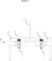
- Shows a side view of the machine comprising wall support and rollers for moving the batten along the wall support.
- Fig. 3
- Shows a top view of the machine comprising a channel, rollers, spacer devices and securing devices.
- Fig. 4
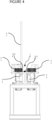
- Shows a side end view of the machine comprising a channel and rollers arranged on either side of the channel.
- Fig. 5
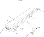
- Shows a ventilated and firesafe batten comprising a fire stopper sandwiched in a space between two longitudinal elements and where the space is secured by a plurality of brackets.
- Fig. 6
- Shows a cross-sectional view of the ventilated and firesafe batten and a spacer device of the machine, the spacer device is arranged for holding the space between the two longitudinal elements so that the bracket can be secured correctly.
- In the following, embodiments of the invention will be discussed in detail with reference to the appended figures. It should be understood, however, that the figures are not intended to limit the invention to the subject-matter depicted in the figures.
-
Figure 1 shows a perspective view of the machine 10 for manufacturing abatten 30. The batten 30 may be a ventilated batten or a ventilated and firesafe batten 29. The term batten 30 refers to ventilated batten or a ventilated and firesafe batten 29. - A ventilated batten comprises a first and a second longitudinal element 31,32 arranged with a distance between each other so that a
space 35 is provided for ventilation through the ventilated batten. The ventilated batten can be transformed to a ventilated and firesafe batten 29 by adding a fire stopper 33 in thespace 35 between the first and second longitudinal elements 31,32. Thus, the automated machine 10 according to the present invention may manufacture a ventilated batten or it can manufacture a ventilated and firesafe batten 29. The latter requires the fire stopper 33 to be pre-mounted into thespace 35 between the longitudinal elements 31,32 before they enter the machine 10. - The machine 10 comprises a
support arrangement 11 for supporting the first and the second longitudinal element 31,32 and so that they are arranged in parallel one over the other or side by side, and with or without the fire stopper 33 sandwiched between them. - The
support arrangement 11 comprises a base support 15 arranged in a horizontal plane x of the machine 10, and a wall support 16 arranged perpendicular to the base support 15 in a vertical plane y, for centralising the first and second longitudinal elements 31,32 on the base support 15. - In
figure 1 , thesupport arrangement 11 comprises two wall supports 16 arranged in parallel and with a distance (F) between each other, providing a channel 17 for guiding the first and second longitudinal elements 31,32 which are arranged one over another. The width of the channel 17 corresponds to the width of the first and second longitudinal elements 31,32 so that the longitudinal elements 31,32 can be moved along the channel 17 by means of therollers 21. - The
rollers 21 are driven by one or moreelectric motors 22 for moving the first and second longitudinal elements 31,32 along the channel 17. The wall support 16 comprises an opening into which theroller 21 extends such that it is in contact with the first and second longitudinal elements 31,32 simultaneously, for moving the longitudinal elements 31,32 simultaneously. - The
electric motors 22 and therollers 21 may be mounted on a moveable arm so that therollers 21 may be adjusted according to different width of the longitudinal elements 31,32 and different width (distance F) of the channel 17. - Thus, according one aspect of the present invention, the first and second longitudinal elements 31,32 of the ventilated and firesafe batten 29, are arranged in parallel, one over the other and with a fire stopper 33 sandwiched between them. The arrangement moves into the machine 10 at one end, and wherein the machine 10 secures the spacer elements 34 such that the longitudinal elements 31,32 are permanently secured with a predetermined distance D (space) between them and with the fire stopper secured in the space. The finished ventilated and firesafe batten 29 exits the machine 10 at the opposite end, as a fully assembled unit.
- According to the present invention, the fire stopper 33 may be mounted into the
space 35 prior to securing the spacer element 34, or the fire stopper 33 may be mounted into thespace 35 after the spacer element 34 is secured. In both embodiments, the fire stopper 33 may be a removeable device or it may not be a removeable device. - To secure the spacer element 34 properly in correct position, the machine 10 further comprises a spacer device 12 adapted for temporary securing and holding the first and second longitudinal elements 31,32 in a distance (D) from each other, the distance corresponding to the
space 35. -
Figure 6 shows that the spacer device 12 comprises a spacer head 18 moveable at least partly into thespace 35 between the first and second longitudinal elements 31,32 for temporary securing and holding thespace 35 before the space (distance D) is permanently secured by the spacer element 34. - The machine 10 may further comprise a
pressure device 25 arranged for pressing the first and second longitudinal elements 31,32 towards each other in a pressure force direction, so that the spacer head 18 is sandwiched or clamped between the longitudinal elements 31,32. - In
figure 3 , thepressure device 25 asserts a vertical force to the longitudinal elements 31,32 so that the spacer head 18 is clamped between them, and wherein the securing device 13 is adapted to secure the spacer element 34 into the first and second longitudinal elements 31,32 in a horizontal direction, which is perpendicular to the vertical force direction of thepressure device 25. - In operation, the spacer head 18 moves into the
space 35 before thepressure device 25 presses the first and second longitudinal elements 31,32 together, so that the spacer head 18 is temporary wedged between the longitudinal elements 31,32. Thereafter, the spacer element 34 is secured to the first and second longitudinal elements 31,32 and thepressure device 25 can be released and the spacer head 18 withdrawn from thespace 35. - The spacer element 34 may be a bracket 36 with two pointed edges 37 arranged to be introduced into respective first and second longitudinal elements 31,32 so that the
space 35 is secured and maintained by the bracket 36. -
Figure 5 shows the bracket 36 comprising a longitudinal body with a protruding grip arranged at either end of the body. The protruding grips extends in a direction perpendicular to the longitudinal direction of the body and may each comprise the pointed edges 37 adapted to be secured, inserted or nailed, into the longitudinal elements 31,32. Furthermore, the bracket 36 may comprise a pair of ledges arranged with a distance from each other on the longitudinal body. The ledges secure the opening of the space 35 (gap) of thebatten 30 by the ledges supporting the opening of thespace 35. - The bracket 36 connects the first longitudinal element 31 to the second longitudinal element 32 and wherein the ledges of the bracket 36 supports the longitudinal elements 31,32 at a distance (D) between each other so that the gap or
space 35 is provided. It may be preferable that the brackets 36 are mounted on either side of the longitudinal batten 30, in pairs at defined intervals along the longitudinal batten. - The machine 10 may comprise an automated sorting device for sorting and arranging the brackets 36 so that they can be fed continuously into the hydraulic or pneumatic cylinder 20 one by one. The automated sorting machine can have different configurations for aligning the brackets in order so that they can be secured one by one.
- The spacer device 12, the
pressure device 25 and/or the securing device 13 may comprise a pneumatic and/or a hydraulic cylinder 20. -
Figure 3 shows the machine 10 comprising fourrollers 21 extending into the channel 17 though openings provided in the wall support 16. The spacer device 12 comprises fourspacer cylinders 24 placed two and two in pairs on either side of the channel 17, and each pair with apressure device 25 arranged in the channel. A pair of securing cylinders 23, facing each other, are placed on either side of the channel 17 between the two pairs ofspacer cylinders 24. - In operation, the
rollers 21 moves thebatten 30 in position along channel 17. The fourspacer cylinders 24 moves the spacer head 18 temporary intospace 35, and wherein thepressure device 25 clamps the spacer head 18 in thespace 35 so that the securing device 13 may secure the bracket 36 in the correct position. Thereafter, thepressure device 25 is released so that the spacer head 18 can be extracted from thespace 35, and wherein therollers 21 can move the batten 30 to the next position. - In embodiment, as shown in
figure 1 andfigure 4 , the base support 15 may be a top surface of a H-beam laid on a side, and wherein the H-beam laid on the side comprises the top surface and a bottom surface section connected by a centre wall and so that a longitudinal space is provided on either side of the centre wall. Thus, the centre wall may also be the symmetrical centre plane of the machine. - A cross-sectional view of the machine 10 is shown in
figure 4 , where the H-beam laid on the side is arranged on top of a floor standing device. The floor standing device may comprise legs for supporting the H-beam from below. - The pneumatic or hydraulic cylinders 20 may be connected to the H-beam and wherein the bracket is secured to the first and second longitudinal elements 31,32 through a bracket opening provided in the wall support 16.
- In embodiment, the machine 10 may comprise two containers placed one either side of a longitudinal axis of the support arrangement, and wherein each of the containers contain three pneumatic cylinders. Two smaller pneumatic cylinders constitute the spacer device 12, for holding the first and second longitudinal elements 31,32 firmly and one larger pneumatic cylinder constituting the securing device 13, adapted to drive/push/press the fastening brackets 36 into the first and second longitudinal elements 31,32.
- The dimension of the cylinder is what determines how much pressure and force is needed to operate it. For example, a 50.50 cylinder may be suitable to hold the longitudinal elements 31,32, and wherein a 100.50 cylinder may be suitable for securing the fastening bracket 36. Thus, the term 50.50 is related to the dimension of the piston, Ø50, and the stroke length is 50mm.
- The machine 10 may comprise two pair of
rollers 21 arranged on either side of the containers in the longitudinal axis of the machine 10. The two pair ofrollers 21 may be synchronised for moving the first and second longitudinal elements 31,32. The two pair ofrollers 21 may be synchronised with the pneumatic cylinders of the two containers for synchronizing the movement of the longitudinal elements 31,32 with the securing of the brackets 36. - According to the invention, the
spacer cylinders 24 thepressure device 25, the securing cylinders 23 and theelectric motors 22 are connected to a PLS (Programmable logic control system) for controlling and synchronising the movement of the first and second longitudinal elements 31,32 with the securing of the spacer element 34.
Claims (11)
- A machine (10) for manufacturing of a batten (30) comprising a first and a second longitudinal element (31,32) having a distance (D) between each other so that a space (35) is provided for ventilation,
characterized in that the machine (10) comprises:- a support arrangement (11) for supporting the first and the second longitudinal element (31,32) and so that they are arranged in parallel;- a spacer device (12) for holding the first and the second longitudinal element (31,32) in the distance (D) from each other, the spacer device (12) comprises a spacer head (18) moveable at least partly into the space (35) between the first and second longitudinal elements (31,32) for holding the space (35); and- a securing device (13) for securing a spacer element (34) into the first and the second longitudinal element (31,32) so that the distance (D) defining the space (35) is secured and maintained by the spacer element (34). - The machine (10) according to claim 1, wherein the support arrangement (11) comprises a base support (15) arranged in a horizontal plane (x) of the machine (10), and a wall support (16) arranged perpendicular to the base support (15) in a vertical plane (y) for centralising the first and second longitudinal elements (31,32) on the base support (15).
- The machine (10) according to claim 2, wherein the support arrangement (11) comprises two wall supports (16) arranged in parallel and with a distance (F) between each other, providing a channel (17) for guiding the first and second longitudinal elements (31,32).
- The machine (10) according to any one of claims 1-3, wherein machine (10) comprises a pressure device (25) arranged for pressing the first and second longitudinal elements (31,32) towards each other in a pressure force direction, so that the spacer head (18) is clamped between the longitudinal elements (31,32).
- The machine (10) according to claim 4, wherein the securing device (13) is adapted to secure the spacer element (34) into the first and second longitudinal elements (31,32) in a direction perpendicular to the pressure force direction of the pressure device (25).
- The machine (10) according to any one of the preceding claims, wherein the spacer device (12) and/or the securing device (13) comprises a pneumatic and/or a hydraulic cylinder (20).
- The machine (10) according to claim 6, wherein the spacer device (12) and the securing device (13) comprises separate pneumatic cylinders (20) adapted for moving the spacer head (18), and for pressing the spacer element (34) into the first and second longitudinal elements, respectively.
- The machine (10) according to any one of the preceding claims, wherein the machine (10) comprises a roller (21) driven by an electric motor (22) for moving the first and second longitudinal elements (31,32) in their longitudinal direction.
- The machine (10) according to claim 2 and 8, wherein the wall support (16) comprises an opening into which the roller (21) extends such that it is in contact with the first and second longitudinal elements (31,32) for moving the longitudinal elements (31,32) simultaneously.
- The machine according to any one of claims 8 or 9, wherein the machine (10) comprises four rollers (21), the spacer device (12) comprises four spacer cylinders (24) and the securing device (13) comprises two securing cylinders (23), and wherein a pair of rollers (21), a pair spacer cylinders (24) and pair of securing cylinders (23) are placed on either side, of a longitudinal axis of the support arrangement (11).
- The machine (10) according to claim 10, wherein the spacer cylinders (24), the securing cylinders (23) and the electric motors (22) are connected to a PLS (Programmable logic control system) for controlling and synchronising the movement of the first and second longitudinal elements (31,32) with the securing of the spacer element (34).
Applications Claiming Priority (1)
| Application Number | Priority Date | Filing Date | Title |
|---|---|---|---|
| NO20231078A NO348426B1 (en) | 2023-10-12 | 2023-10-12 | A machine for manufacturing of a batten |
Publications (1)
| Publication Number | Publication Date |
|---|---|
| EP4538006A1 true EP4538006A1 (en) | 2025-04-16 |
Family
ID=93154463
Family Applications (1)
| Application Number | Title | Priority Date | Filing Date |
|---|---|---|---|
| EP24205855.0A Pending EP4538006A1 (en) | 2023-10-12 | 2024-10-10 | A machine for manufacturing of a batten |
Country Status (2)
| Country | Link |
|---|---|
| EP (1) | EP4538006A1 (en) |
| NO (1) | NO348426B1 (en) |
Citations (5)
| Publication number | Priority date | Publication date | Assignee | Title |
|---|---|---|---|---|
| US2631956A (en) * | 1948-06-01 | 1953-03-17 | Bostadsforskning Ab | Method and device for the manufacture of box girders |
| US4123315A (en) * | 1976-11-05 | 1978-10-31 | Wm. A. Nickerson & Co., Ltd. | Machine for assembling wood I-beams |
| US4840207A (en) * | 1985-08-09 | 1989-06-20 | Mitek Industries, Inc. | Apparatus for making wooden I-beams |
| US4967534A (en) * | 1985-08-09 | 1990-11-06 | Mitek Holding, Inc. | Wood I-beams and methods of making same |
| WO2022253786A1 (en) | 2021-05-31 | 2022-12-08 | Bergene Holm As | A ventilated façade cladding system |
Family Cites Families (4)
| Publication number | Priority date | Publication date | Assignee | Title |
|---|---|---|---|---|
| DE855900C (en) * | 1950-08-18 | 1952-11-17 | Hans Vollmar | Wooden member, e.g. B. beam, support, truss rod or the like. |
| US4002116A (en) * | 1975-05-09 | 1977-01-11 | Jack N. Schmitt | Apparatus for forming trusses |
| DE8326657U1 (en) * | 1983-09-16 | 1985-02-28 | Köhnke, Ernst-Ulrich, Dipl.-Ing. (FH), 4459 Uelsen | WOODEN COMPONENT FOR THE PRODUCTION OF SOUND-RESISTANT COMPONENTS |
| US6651306B1 (en) * | 1999-07-23 | 2003-11-25 | Mitek Holdings, Inc. | Apparatus and method for fabricating flat trusses |
-
2023
- 2023-10-12 NO NO20231078A patent/NO348426B1/en unknown
-
2024
- 2024-10-10 EP EP24205855.0A patent/EP4538006A1/en active Pending
Patent Citations (5)
| Publication number | Priority date | Publication date | Assignee | Title |
|---|---|---|---|---|
| US2631956A (en) * | 1948-06-01 | 1953-03-17 | Bostadsforskning Ab | Method and device for the manufacture of box girders |
| US4123315A (en) * | 1976-11-05 | 1978-10-31 | Wm. A. Nickerson & Co., Ltd. | Machine for assembling wood I-beams |
| US4840207A (en) * | 1985-08-09 | 1989-06-20 | Mitek Industries, Inc. | Apparatus for making wooden I-beams |
| US4967534A (en) * | 1985-08-09 | 1990-11-06 | Mitek Holding, Inc. | Wood I-beams and methods of making same |
| WO2022253786A1 (en) | 2021-05-31 | 2022-12-08 | Bergene Holm As | A ventilated façade cladding system |
Also Published As
| Publication number | Publication date |
|---|---|
| NO20231078A1 (en) | 2025-01-20 |
| NO348426B1 (en) | 2025-01-20 |
Similar Documents
| Publication | Publication Date | Title |
|---|---|---|
| KR101958214B1 (en) | Apparatus and method for manufacturing preformed bar arranged structure for construction which enables to withdraw and autumatically cut wires | |
| KR101958213B1 (en) | Apparatus and method for manufacturing preformed bar arranged structure for construction | |
| CA2950511C (en) | Machine and method for cold semi-continuous bending of low ductility profiles | |
| DE3505841A1 (en) | DEVICE FOR BRACKING LARGE-FORMAT WALL ARTIFICIAL STONES | |
| CN114850302B (en) | Method for manufacturing bi-directional deformable metal roof ridge node | |
| EP2503077A1 (en) | Self-climbing perimetric protection system adaptable to buildings undergoing construction having a variable vertical projection | |
| NO20231078A1 (en) | A machine for manufacturing of a batten | |
| WO2009045376A1 (en) | Automated three nail gun tool dolly | |
| CN119427567A (en) | ALC wall panel slotting device | |
| DE2644650C3 (en) | Teaching about building gable walls in the roof area | |
| EP0163781B1 (en) | Method and device for manufacturing a composite prestressed wooden beam | |
| CN114905595B (en) | Preprocessing equipment and processing control method for building construction template | |
| CN115815901A (en) | Construction equipment and process for welding steel for building | |
| US4086693A (en) | Manufacture of construction elements | |
| CN222607838U (en) | Auxiliary device for bending constructional engineering reinforcing steel bars | |
| EP2290169B1 (en) | Profile module for producing a ceiling construction | |
| CN112958722A (en) | Bending equipment for building stirrups | |
| DE20317225U1 (en) | Construction element for force transfer, especially for retrofitting between two building parts during building renovation, has a wedge shape consisting of an outer covering element and a pressure-stable filling material | |
| CN118774401B (en) | An anti-slip device based on prestressed steel strands with added haunch beams and an installation method | |
| CN116950231B (en) | Adjustable portal | |
| CN222962050U (en) | A wrapped formwork for engineering pile maintenance | |
| CN220336109U (en) | Assembled steel structural member | |
| DE10229245A1 (en) | Detachable fixed connection between two components has connecting elements on structural parts connected together by clamping or clip connection | |
| CN110255423A (en) | A kind of multistage screw rod for promotion combines lifting device with lift cylinder | |
| DE19804166C2 (en) | Facade cladding with facade panels |
Legal Events
| Date | Code | Title | Description |
|---|---|---|---|
| PUAI | Public reference made under article 153(3) epc to a published international application that has entered the european phase |
Free format text: ORIGINAL CODE: 0009012 |
|
| STAA | Information on the status of an ep patent application or granted ep patent |
Free format text: STATUS: THE APPLICATION HAS BEEN PUBLISHED |
|
| AK | Designated contracting states |
Kind code of ref document: A1 Designated state(s): AL AT BE BG CH CY CZ DE DK EE ES FI FR GB GR HR HU IE IS IT LI LT LU LV MC ME MK MT NL NO PL PT RO RS SE SI SK SM TR |
|
| STAA | Information on the status of an ep patent application or granted ep patent |
Free format text: STATUS: REQUEST FOR EXAMINATION WAS MADE |
|
| 17P | Request for examination filed |
Effective date: 20251010 |