EP4537996A1 - Manipulator arm - Google Patents
Manipulator arm Download PDFInfo
- Publication number
- EP4537996A1 EP4537996A1 EP22946780.8A EP22946780A EP4537996A1 EP 4537996 A1 EP4537996 A1 EP 4537996A1 EP 22946780 A EP22946780 A EP 22946780A EP 4537996 A1 EP4537996 A1 EP 4537996A1
- Authority
- EP
- European Patent Office
- Prior art keywords
- link
- cover
- end member
- attached
- actuator
- Prior art date
- Legal status (The legal status is an assumption and is not a legal conclusion. Google has not performed a legal analysis and makes no representation as to the accuracy of the status listed.)
- Granted
Links
Images





Classifications
-
- B—PERFORMING OPERATIONS; TRANSPORTING
- B25—HAND TOOLS; PORTABLE POWER-DRIVEN TOOLS; MANIPULATORS
- B25J—MANIPULATORS; CHAMBERS PROVIDED WITH MANIPULATION DEVICES
- B25J9/00—Program-controlled manipulators
- B25J9/10—Program-controlled manipulators characterised by positioning means for manipulator elements
- B25J9/106—Program-controlled manipulators characterised by positioning means for manipulator elements with articulated links
- B25J9/1065—Program-controlled manipulators characterised by positioning means for manipulator elements with articulated links with parallelograms
-
- A—HUMAN NECESSITIES
- A61—MEDICAL OR VETERINARY SCIENCE; HYGIENE
- A61B—DIAGNOSIS; SURGERY; IDENTIFICATION
- A61B34/00—Computer-aided surgery; Manipulators or robots specially adapted for use in surgery
- A61B34/30—Surgical robots
-
- A—HUMAN NECESSITIES
- A61—MEDICAL OR VETERINARY SCIENCE; HYGIENE
- A61B—DIAGNOSIS; SURGERY; IDENTIFICATION
- A61B34/00—Computer-aided surgery; Manipulators or robots specially adapted for use in surgery
- A61B34/30—Surgical robots
- A61B34/37—Leader-follower robots
-
- A—HUMAN NECESSITIES
- A61—MEDICAL OR VETERINARY SCIENCE; HYGIENE
- A61B—DIAGNOSIS; SURGERY; IDENTIFICATION
- A61B34/00—Computer-aided surgery; Manipulators or robots specially adapted for use in surgery
- A61B34/70—Manipulators specially adapted for use in surgery
-
- B—PERFORMING OPERATIONS; TRANSPORTING
- B25—HAND TOOLS; PORTABLE POWER-DRIVEN TOOLS; MANIPULATORS
- B25J—MANIPULATORS; CHAMBERS PROVIDED WITH MANIPULATION DEVICES
- B25J19/00—Accessories fitted to manipulators, e.g. for monitoring, for viewing; Safety devices combined with or specially adapted for use in connection with manipulators
- B25J19/0075—Means for protecting the manipulator from its environment or vice versa
-
- A—HUMAN NECESSITIES
- A61—MEDICAL OR VETERINARY SCIENCE; HYGIENE
- A61B—DIAGNOSIS; SURGERY; IDENTIFICATION
- A61B34/00—Computer-aided surgery; Manipulators or robots specially adapted for use in surgery
- A61B34/30—Surgical robots
- A61B2034/305—Details of wrist mechanisms at distal ends of robotic arms
Definitions
- the present disclosure relates to a manipulator arm.
- the surgical assist system includes manipulator arms that hold instruments to be used for surgery (hereinafter, also referred to as "surgical instruments").
- surgical instruments may include endoscopes, forceps, electric scalpels, and other instruments to be used in surgery.
- the manipulator arms hold the surgical instruments according to the types and circumstances of the surgery.
- the link mechanisms used in the manipulator arms may include a four-bar linkage.
- Examples of the four-bar linkage may include a parallel link in which the respective lengths of opposite links are equal.
- Patent Document 1 discloses a manipulator arm using the parallel link.
- Patent Document 1 Japanese Unexamined Patent Application Publication No. 2018-175863
- the manipulator arm is provided with covers, and the covers surround the link mechanisms, the actuator, or the like.
- the covers are used to separate the interior and exterior of the manipulator arm.
- the first cover and the second cover are placed on the same first link, and thus, the first cover and the second cover do not slide against each other when the parallel link is moved.
- placing the first cover and the second cover on the same first link may be understood to mean, for example, that both the first cover and the second cover are attached to the first link.
- a movement distance of the first cover and the second cover, which are placed on the first link is shorter than a case where, for example, the second cover is placed on the second link. That is, in comparison with the case where the second cover is placed on the second link, the movement distance of the first cover and the second cover with respect to the entire manipulator arm is shortened, and the first cover and the second cover are less likely to slide against other components.
- a first end of the first link is attached at a rotation center of the first end member, and a second end of the first link is attached at a rotation center of the second end member.
- the first link is attached at the rotating centers of the first end member and the second end member, it is possible to easily control the movement of the first link even when the parallel link moves. In other words, even when the second link moves with the rotational movement of the first end member and the second end member, the first link moves less relative to the entire manipulator arm (in other words, the travel distance of the first link relative to the entire manipulator arm can be smaller).
- a first distance from the position where the first link is attached to the position where the second link is attached in the first end member is equal to a second distance from the position where the first link is attached to the position where the actuator is attached in the first end member.
- the movement of the first link is easily controlled even when the parallel link is moved by the driving force of the actuator.
- the first link moves less relative to the entire manipulator arm 1 (in other words, the travel distance of the first link relative to the entire manipulator arm can be smaller).
- the manipulator arm of the present disclosure has an effect that the first cover and the second cover are less likely to slide against each other, whereby the manipulator arm can be easily used in a clean surgery area.
- the manipulator arm 1 includes, as shown in FIG. 1 , a first attachment portion 10, a second attachment portion 20 arranged to be spaced apart from the first attachment portion 10, and an arm portion 30 extending between the first attachment portion 10 and the second attachment portion 20.
- the first attachment portion 10 has a configuration for attaching the manipulator arm 1 to a surgery assistance robot.
- the surgery assistance robot is not shown in FIGS. 1 to 9 .
- the first attachment portion 10 may have a configuration for connecting a manipulator arm other than the manipulator arm 1.
- the attachment plate 11 is, as shown in FIG. 1 , a circular plate-shaped member having a cylindrical or columnar projection in its center region.
- the attachment plate 11 is attached to the first end members 15A, 15B.
- Each of the first end members 15A, 15B is a plate-shaped member having a substantially D-shaped outer shape.
- the attachment plate 11 is attached to the straight portions of the D-shapes of the first end members 15A, 15B.
- the first end members 15A, 15B are arranged with their curved portions of the D-shapes facing an arm portion 30 side.
- the first end members 15A, 15B are arranged side by side with the first links 31A, 31B, the second links 41A, 41B and the actuator 51 interposed therebetween.
- the first end members 15A, 15B are fixed to each other in a state of being arranged side by side with a given space therebetween.
- the second attachment portion 20 has a configuration for attaching another additional manipulator arm to the manipulator arm 1 (however, a detailed illustration is omitted here).
- the second attachment portion 20 may have a configuration for attaching a device other than the manipulator arm to the manipulator arm 1, such as a device for holding an instrument to be used for surgery.
- the second attachment cover 22A is a member covering the second end member 25A so as to conceal it from the exterior and having a cylindrical shape with a bottom surface.
- the second attachment cover 22A is attached to the second end member 25A with its cylindrical opening facing the second end member 25A.
- the second attachment cover 22B is a member covering the second end member 25B so as to conceal it from the exterior and having a cylindrical shape with a bottom surface.
- the second attachment cover 22B is attached to the second end member 25B with its cylindrical opening facing the second end member 25B.
- the second end members 25A, 25B are, as shown in FIGS. 3 , 4 , 5 and the like, members forming the parallel links together with the first end members 15A, 15B, the first links 31A, 31B, and the second links 41A, 41B.
- the second end members 25A, 25B are plate-shaped members having a substantially D-shaped outer shape.
- the second end members 25A, 25B are arranged with their curved portions of the D-shapes facing the arm portion 30 side.
- the second end members 25A, 25B are arranged side by side with the first links 31A, 31B, the second links 41A, 41B and the actuator 51 interposed therebetween.
- the second end members 25A, 25B are fixed to each other in a state of being arranged side by side with a given space therebetween.
- the first links 31A, 31B are rod-like members arranged to extend between the first attachment portion 10 and the second attachment portion 20.
- the first link 31A is a rod-like member arranged to extend between the first end members 15A, 15B and the second end members 25A, 25B.
- the first link 31B is a rod-like member arranged to extend between the first end members 15A, 15B and the second end members 25A, 25B.
- the first link 31A and the first link 31B have the same configuration.
- the first link 31A is arranged close to the first end member 15A and the second end member 25A.
- the first link 31B is arranged close to the first end member 15B and the second end member 25B.
- the first links 31A, 31B are members forming the parallel links together with the first end members 15A, 15B, the second end members 25A, 25B and the second links 41A, 41B.
- the end of the first link 31A on a first attachment portion 10 side is pivotably attached to the first end members 15A, 15B about a pivot axis 32L through a rotational shaft 32A.
- the end of the first link 31B on the first attachment portion 10 side is pivotably attached to the first end members 15A, 15B about a pivot axis 32L through a rotational shaft 32A.
- the rotational shaft 32A is a cylindrical member arranged to extend at least between the first links 31A, 31B.
- the central axis of the rotational shaft 32A is the pivot axis 32L.
- the pivot axis 32L passes through a position at or near the center of the curved portions of the D-shapes in the first end members 15A, 15B.
- the end of the first link 31A on a second attachment portion 20 side is pivotably attached to the second end members 25A, 25B about a pivot axis 33L through a rotational shaft 33A.
- the end of the first link 31B on the second attachment portion 20 side is pivotably attached to the second end members 25A, 25B about the pivot axis 33L through the rotational shaft 33A.
- the rotational shaft 33A is a cylindrical member arranged to extend at least between the first links 31A, 31B.
- the central axis of the rotational shaft 33A is the pivot axis 33L.
- the pivot axis 33L passes through a position at or near the center of the curved portions of the D-shapes in the second end members 25A, 25B.
- the first links 31A, 31B are arranged to be spaced from each other in a direction in which the pivot axis 32L and the pivot axis 33L extend.
- the first link 31A is arranged in parallel with the second link 41A with a space therebetween.
- the first link 31B is arranged in parallel with the second link 41B with a space therebetween.
- the second links 41A, 41B are rod-like members arranged to extend between the first attachment portion 10 and the second attachment portion 20.
- the second link 41A is a rod-like member arranged to extend between the first end members 15A, 15B and the second end members 25A, 25B.
- the second link 41B is a rod-like member arranged to extend between the first end members 15A, 15B and the second end members 25A, 25B.
- the second link 41A and the second link 41B have the same configuration.
- the second link 41A is arranged close to the first end member 15A and the second end member 25A.
- the second link 41B is arranged close to the first end member 15B and the second end member 25B.
- the second links 41A, 42B form parallel links together with the first end members 15A, 15B, the second end members 25A, 25B, and the first links 31A, 31B.
- the end of the second link 41A on the second attachment portion 20 side is pivotably attached to the second end members 25A, 25B about a pivot axis 43L through a rotational shaft 43A.
- the end of the second link 41B on the second attachment portion 20 side is pivotably attached to the second end members 25A, 25B about the pivot axis 43L through the rotational shaft 43A.
- the rotational shaft 43A is a cylindrical member arranged to extend between the second links 41A, 41B.
- the central axis of the rotational shaft 43A is the pivot axis 43L.
- the pivot axis 43L passes through a position apart from the center of the curved portions of the D-shapes in the second end members 25A, 25B.
- the second links 41A, 41B are arranged to be spaced from each other in a direction in which the pivot axis 42L and the pivot axis 43L extend.
- the second link 41A is arranged in parallel with the first link 31A with a space therebetween.
- the second link 41B is arranged in parallel with the first link 31B with a space therebetween.
- the actuator 51 is driven by a pressurized gas supplied externally to the cylinder, thereby changing its longitudinal length. Air is used as the gas.
- the actuator 51 may use gases other than air.
- the actuator 51 may use a fluid other than gases.
- the actuator 51 is provided with a spring 53 that generates a biasing force.
- the longitudinal length of the actuator 51 is controlled by the relationship between the biasing force of the spring 53 and the force generated in the cylinder that is externally supplied with air.
- the magnitude of the force exerted by the actuator 51 on the parallel links is controlled. Note that the actuator 51 does not necessarily include the spring 53.
- the end of the actuator 51 on a first end member 15A, 15B side is pivotably attached to the first end members 15A, 15B about a pivot axis 52L through a rotational shaft 52A.
- the central axis of the rotational shaft 52A is the pivot axis 52L.
- the end of the actuator 51 on the first end members 15A, 15B side is, as shown in FIGS. 4 and 5 , attached at a position 52P that sandwiches, between itself and a position 42P where the second links 41A, 41B are attached in the first end members 15A, 15B, a position 32P where the first links 31A, 31B are attached.
- the first end member 15A is not shown in FIGS. 4 and 5 .
- the position 32P is a position through which the pivot axis 32L passes in the first end members 15A, 15B.
- the position 32P is also a center position of the relative rotational movement of the first end members 15A, 15B and the arm portion 30.
- the position 42P is a position through which the pivot axis 42L passes in the first end members 15A, 15B.
- the position 52P is a position through which the pivot axis 52L passes in the first end members 15A, 15B.
- the end of the actuator 51 on a second end members 25A, 25B side is pivotably attached to the second end members 25A, 25B about the pivot axis 43L through the rotational shaft 43A.
- the end of the actuator 51 on the second end members 25A, 25B side is attached at a position 43P where the second links 41A, 41B are attached in the second end members 25A, 25B.
- the position 43P is a position through which a pivot axis 43L passes in the second end members 25A, 25B.
- a position 33P where the first links 31A, 31B are attached in the second end members 25A, 25B is a position through which a pivot axis 33L passes.
- the position 33P is also a center position of the relative rotational movement of the second end members 25A, 25B and the arm portion 30.
- the position 32P, the position 42P, and the position 52P are aligned side by side on the same straight line.
- a first distance D1 from the position 32P to the position 42P is equal to a second distance D2 from the position 32P to the position 52P.
- the position 32P, the position 42P and the position 52P are not necessarily aligned side by side on the same straight line. It is preferable that the first distance D1 is equal to the second distance D2; however, they may have different lengths to the extent not departing from the gist of the present disclosure.
- the first cover 61 and the second cover 71 are members forming the outer shape of the arm portion 30, as shown in FIG. 3 , and cover at least the second link 41 and the actuator 51.
- the second cover 71 is a member placed on the first links 31, 31B and positioned on a second link 41A, 41B side of the first links 31A, 31B.
- the end of the second cover 71 on the first end member 15A, 15B side has a semi-cylindrical shape with the pivot axis 32L as the center.
- the end on the second end member 25A, 25B side has a semi-cylindrical shape with the pivot axis 33L as the center.
- the longitudinal central region of the second cover 71 is formed into a half-pipe shape with its central axis extending from the first attachment portion 10 toward the second attachment portion 20 on the actuator 51 side.
- FIGS. 6 to 9 the movement of the manipulator arm 1 of the above configuration is described with reference to FIGS. 6 to 9 .
- the movement when the longitudinal dimension of the actuator 51 is shortened is described with reference to FIGS. 6 and 7 .
- the movement when the actuator 51 is retracted is described with reference to FIGS. 6 and 7 .
- FIG. 6 shows the movement of the manipulator arm 1 in the state where the first end members 15A, 15B are fixed to a fixed portion 80 of the surgery assistance robot.
- FIG. 6 shows the movement of the manipulator arm 1 in the state where the attachment plate 11 shown in FIG. 1 is fixed to the fixed portion 80 of the surgery assistance robot.
- the first end member 15A, the second end member 25A, and the second link 41B are not shown.
- the first links 31A, 31B move rotationally about the rotational shaft 32A with respect to the first end members 15A, 15B. In other words, they move rotationally to the right (also referred to as "clockwise") about the pivot axis 32L in FIG. 6 .
- the second link 41 moves rotationally about the rotational shaft 42A with respect to the first end member 15. In other words, it moves rotationally to the right (clockwise) about the pivot axis 32L in FIG. 6 .
- the second end members 25A, 25B move upward in FIG. 6 with the rotational movement of the first links 31A, 31B and the second links 41A, 41B. In other words, they rotate clockwise about the pivot axis 32L in FIG. 6 .
- the second end members 25A, 25B move rotationally about the rotational shaft 33A. In other words, they rotate to the left (also referred to as "counterclockwise") about the pivot axis 33L in FIG. 6 .
- the second end members 25A, 25B maintain their postures relative to the first end members 15A, 15B while changing their positions relative to the first end members 15A, 15B.
- FIG. 7 shows a relative movement between the first end members 15A, 15B and the second end members 25A, 25B when the longitudinal dimension of the actuator 51 is shortened.
- the movement of the manipulator arm 1 is the same as that shown in FIG. 6 .
- the description focuses on the relative movement between the first end members 15A, 15B and the second end members 25A, 25B.
- the first end member 15A, the second end member 25A, and the second link 41B are not shown.
- the second end members 25A, 25B move rotationally about the rotational shaft 33A. In other words, they rotate to the left (counterclockwise) about the pivot axis 33L in FIG. 6 .
- the second link 41A moves toward the first end members 15A, 15B relative to the first link 31A with the rotation of the first end members 15A, 15B and the second end members 25A, 25B.
- the second link 41B moves toward the first end members 15A, 15B relative to the first link 31B with the rotation of the first end members 15A, 15B and the second end members 25A, 25B.
- FIG. 8 shows the movement of the manipulator arm 1 in the state where the first end members 15A, 15B are fixed to the fixed portion 80 of the surgery assistance robot. In other words, it shows the movement of the manipulator arm 1 in the state where the attachment plate 11 shown in FIG. 1 is fixed to the fixed portion 80 of the surgery assistance robot.
- the first end member 15A, the second end member 25A, and the second link 41B are not shown.
- the second end members 25A, 25B move downward in FIG. 8 with the rotational movement of the first link 31 and the second link 41. In other words, they rotate to the left (counterclockwise) about the pivot axis 32L in FIG. 8 .
- the second end members 25A, 25B move rotationally about the rotational shaft 33A. In other words, they rotate to the right (clockwise) about the pivot axis 33L in FIG. 8 .
- the second end members 25A, 25B maintain their postures relative to the first end members 15A, 15B while changing their positions relative to the first end members 15A, 15B.
- FIG. 9 shows a relative movement between the first end members 15A, 15B and the second end members 25A, 25B when the longitudinal dimension of the actuator 51 is lengthened.
- the movement of the manipulator arm 1 is the same as that shown in FIG. 8 .
- the description focuses on the relative movement between the first end members 15A, 15B and the second end members 25A, 25B.
- the first end member 15A, the second end member 25A, and the second link 41B are not shown.
Landscapes
- Engineering & Computer Science (AREA)
- Health & Medical Sciences (AREA)
- Robotics (AREA)
- Surgery (AREA)
- Life Sciences & Earth Sciences (AREA)
- Mechanical Engineering (AREA)
- Medical Informatics (AREA)
- Heart & Thoracic Surgery (AREA)
- Biomedical Technology (AREA)
- Molecular Biology (AREA)
- Animal Behavior & Ethology (AREA)
- General Health & Medical Sciences (AREA)
- Public Health (AREA)
- Veterinary Medicine (AREA)
- Nuclear Medicine, Radiotherapy & Molecular Imaging (AREA)
- Manipulator (AREA)
Abstract
Description
- The present disclosure relates to a manipulator arm.
- In recent years, surgery using a surgical assist system has been becoming popular (see, e.g., Patent Document 1). The surgical assist system includes manipulator arms that hold instruments to be used for surgery (hereinafter, also referred to as "surgical instruments"). Examples of the surgical instruments may include endoscopes, forceps, electric scalpels, and other instruments to be used in surgery. The manipulator arms hold the surgical instruments according to the types and circumstances of the surgery.
- The manipulator arms have one or more link mechanisms and move the link mechanisms to thereby move the surgical instruments to desired positions and hold them at the positions. The link mechanisms are moved by driving forces provided by actuators mounted on the manipulator arms.
- The link mechanisms used in the manipulator arms may include a four-bar linkage. Examples of the four-bar linkage may include a parallel link in which the respective lengths of opposite links are equal.
Patent Document 1 discloses a manipulator arm using the parallel link. - Patent Document 1:
Japanese Unexamined Patent Application Publication No. 2018-175863 - In some cases, the manipulator arm is provided with covers, and the covers surround the link mechanisms, the actuator, or the like. The covers are used to separate the interior and exterior of the manipulator arm.
- In the case where the link mechanism is a parallel link, a first cover and a second cover may be respectively attached to a first link and a second link facing each other. When the parallel link moves, the first link and the second link move in relatively opposite directions. The first cover moves together with the first link equipped with the first cover, and the second cover moves together with the second link equipped with the second cover. Therefore, the parallel link of the manipulator arm can move in a state where the first cover and the second cover are attached.
- On the other hand, in a state where the first cover and the second cover are in contact, when the first cover and the second cover move relatively to each other, there is a possibility that foreign matter may be generated as the first cover and the second cover slide against each other. Since the manipulator arm is used in a clean surgical area, it is preferable that no foreign matter be generated.
- If a gap is provided between the first cover and the second cover, it is possible to inhibit the generation of foreign matter due to the sliding of the first cover and the second cover. However, the internal space of the first cover and the second cover can be connected to the external space through the gap.
- Sliding mechanisms, such as an actuator and a parallel link, are arranged in the internal space of both the first cover and the second cover. There is a possibility that foreign matter may be generated in these sliding mechanisms, and the gap described above may allow the generated foreign matter to be released to the exterior of the manipulator arm. In the manipulator arm used in a clean surgery area, it is preferable that no foreign matter be released.
- The present disclosure discloses an example of a manipulator arm suitable for use in a clean surgery area.
- A manipulator arm in one aspect of the present disclosure includes a parallel link provided with a first end member and a second end member arranged to be spaced apart from each other, and a first link and a second link that are arranged to extend between the first end member and the second end member and that are arranged side by side with a space therebetween, the manipulator arm further comprising: an actuator that is arranged to extend between the first end member and the second end member and that is configured to change its longitudinal length to thereby generate a driving force to rotationally move the first end member and the second end member relative to each other, wherein a position where the actuator is attached to the first end member is a position that sandwiches, between itself and a position where the second link is attached, a position where the first link is attached, and wherein a position where the actuator is attached to the second end member is a position same as a position where the second link is attached; a first cover placed on the first link from a side opposite the second link with respect to the first link, the first cover covering at least the actuator; and a second cover placed on the first link from a second link side with respect to the first link, the second cover covering at least the second link and the actuator.
- In the manipulator arm of the present disclosure, the first cover and the second cover are placed on the same first link, and thus, the first cover and the second cover do not slide against each other when the parallel link is moved. Here, placing the first cover and the second cover on the same first link may be understood to mean, for example, that both the first cover and the second cover are attached to the first link.
- Placing the first cover and the second cover on the first link makes it less likely that a gap is formed between the first cover and the second cover. In other words, it is easy to reduce the gap in the design. By attaching both the first cover and the second cover to the first link, even if there is a gap between the first cover and the second cover, the first link is present in the gap, and therefore, the gap can be covered by the first link.
- A position where the actuator is attached to the first end member sandwiches, between itself and a position where the second link is attached, a position where the first link is attached, and a position where the actuator is attached to the second end member is the same as a position where the second link is attached. Therefore, when the parallel link moves, a movement distance of the first link is shorter than a movement distance of the second link. Thus, a movement distance of the first cover and the second cover, which are placed on the first link, is shorter than a case where, for example, the second cover is placed on the second link. That is, in comparison with the case where the second cover is placed on the second link, the movement distance of the first cover and the second cover with respect to the entire manipulator arm is shortened, and the first cover and the second cover are less likely to slide against other components.
- In the manipulator arm in one aspect of the present disclosure, it is preferable that a first end of the first link is attached at a rotation center of the first end member, and a second end of the first link is attached at a rotation center of the second end member.
- Since the first link is attached at the rotating centers of the first end member and the second end member, it is possible to easily control the movement of the first link even when the parallel link moves. In other words, even when the second link moves with the rotational movement of the first end member and the second end member, the first link moves less relative to the entire manipulator arm (in other words, the travel distance of the first link relative to the entire manipulator arm can be smaller).
- In the manipulator arm in one aspect of the present disclosure, it is preferable that a first distance from the position where the first link is attached to the position where the second link is attached in the first end member is equal to a second distance from the position where the first link is attached to the position where the actuator is attached in the first end member.
- Since the first distance is equal to the second distance, the movement of the first link is easily controlled even when the parallel link is moved by the driving force of the actuator. In other words, even when the second link moves with the rotational movement of the first end member and the second end member by the driving force of the actuator, the first link moves less relative to the entire manipulator arm 1 (in other words, the travel distance of the first link relative to the entire manipulator arm can be smaller).
- The manipulator arm of the present disclosure has an effect that the first cover and the second cover are less likely to slide against each other, whereby the manipulator arm can be easily used in a clean surgery area.
-
-
FIG. 1 is a perspective view illustrating the appearance of a manipulator arm of this embodiment. -
FIG. 2 is a perspective view illustrating the configuration of the manipulator arm ofFIG. 1 . -
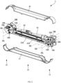
FIG. 3 is an exploded perspective view illustrating the configuration of the manipulator arm ofFIG. 1 . -
FIG. 4 illustrates the arrangement of a first link, a second link, and an actuator ofFIG. 3 . -
FIG. 5 illustrates the arrangement of a first link, a second link, and an actuator ofFIG. 3 . -
FIG. 6 illustrates the movement of the manipulator arm when the actuator is retracted. -
FIG. 7 illustrates the relative movement of a first end member and a second end member ofFIG. 6 . -
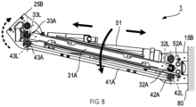
FIG. 8 illustrates the movement of the manipulator arm when the actuator is extended. -
FIG. 9 illustrates the relative movement of the first end member and the second end member ofFIG. 8 . - 1...manipulator arm, 15...first end member, 25...second end member, 31...first link, 41...second link, 51...actuator, 61...first cover, 71...second cover
- A
manipulator arm 1 according to one embodiment of the present disclosure is described with reference toFIGS. 1 to 9 . Themanipulator arm 1 corresponds to an arm portion in a master-slave type surgery assistance robot. Themanipulator arm 1 may correspond to an arm portion in a surgery assistance robot other than the master-slave type. Themanipulator arm 1 may correspond to an arm portion in a surgery assistance device other than the surgery assistance robot. - The
manipulator arm 1 includes, as shown inFIG. 1 , afirst attachment portion 10, asecond attachment portion 20 arranged to be spaced apart from thefirst attachment portion 10, and anarm portion 30 extending between thefirst attachment portion 10 and thesecond attachment portion 20. - The
first attachment portion 10 has a configuration for attaching themanipulator arm 1 to a surgery assistance robot. The surgery assistance robot is not shown inFIGS. 1 to 9 . Thefirst attachment portion 10 may have a configuration for connecting a manipulator arm other than themanipulator arm 1. - The
first attachment portion 10 includes, as shown inFIG. 2 ,first end members first attachment portion 10 further includes, as shown inFIG. 1 , anattachment plate 11 used for installation onto the surgery assistance robot and first attachment covers 12A, 12B covering thefirst attachment portion 10. Thefirst attachment cover 12A and thefirst attachment cover 12B have the same configuration. Thefirst end member 15A and thefirst end member 15B have the same configuration. - The
attachment plate 11 is, as shown inFIG. 1 , a circular plate-shaped member having a cylindrical or columnar projection in its center region. Theattachment plate 11 is attached to thefirst end members - The
first attachment cover 12A is a member covering thefirst end member 15A so as to conceal it from the exterior and having a cylindrical shape with a bottom surface. Thefirst attachment cover 12A is attached to thefirst end member 15A with its cylindrical opening facing thefirst end member 15A. - The
first attachment cover 12B is a member covering thefirst end member 15B so as to conceal it from the exterior and having a cylindrical shape with a bottom surface. Thefirst attachment cover 12B is attached to thefirst end member 15B with its cylindrical opening facing thefirst end member 15B. - The
first end members FIGS. 3 ,4 ,5 and the like, members forming parallel links together with thesecond end members first links second links first end member 15A, thesecond end member 25A, thefirst link 31A, and thesecond link 41A form one parallel link, and thefirst end member 15B, thesecond end member 25B, thefirst link 31B, and thesecond link 41B form one parallel link. - Each of the
first end members attachment plate 11 is attached to the straight portions of the D-shapes of thefirst end members first end members arm portion 30 side. Thefirst end members first links second links actuator 51 interposed therebetween. Thefirst end members - The
second attachment portion 20 has a configuration for attaching another additional manipulator arm to the manipulator arm 1 (however, a detailed illustration is omitted here). Thesecond attachment portion 20 may have a configuration for attaching a device other than the manipulator arm to themanipulator arm 1, such as a device for holding an instrument to be used for surgery. - The
second attachment portion 20 includes, as shown inFIG. 1 , second attachment covers 22A, 22B covering thesecond attachment portion 20. Thesecond attachment portion 20 includes, as shown inFIGS. 2 and3 or the like, thesecond end members second attachment cover 22A and thesecond attachment cover 22B have the same configuration. Thesecond end member 25A and thesecond end member 25B have the same configuration. - As shown in
FIG. 1 , thesecond attachment cover 22A is a member covering thesecond end member 25A so as to conceal it from the exterior and having a cylindrical shape with a bottom surface. Thesecond attachment cover 22A is attached to thesecond end member 25A with its cylindrical opening facing thesecond end member 25A. - The
second attachment cover 22B is a member covering thesecond end member 25B so as to conceal it from the exterior and having a cylindrical shape with a bottom surface. Thesecond attachment cover 22B is attached to thesecond end member 25B with its cylindrical opening facing thesecond end member 25B. Thesecond end members FIGS. 3 ,4 ,5 and the like, members forming the parallel links together with thefirst end members first links second links - The
second end members second end members arm portion 30 side. Thesecond end members first links second links actuator 51 interposed therebetween. Thesecond end members - The
arm portion 30 has a rod-like outer shape and has a configuration for being pivotably attached to each of thefirst attachment portion 10 and thesecond attachment portion 20. Thearm portion 30 includes, as shown inFIGS. 3 ,4 and5 , thefirst links second links actuator 51, afirst cover 61 and asecond cover 71. - The
first links first attachment portion 10 and thesecond attachment portion 20. Specifically, thefirst link 31A is a rod-like member arranged to extend between thefirst end members second end members first link 31B is a rod-like member arranged to extend between thefirst end members second end members first link 31A and thefirst link 31B have the same configuration. Thefirst link 31A is arranged close to thefirst end member 15A and thesecond end member 25A. Thefirst link 31B is arranged close to thefirst end member 15B and thesecond end member 25B. Thefirst links first end members second end members second links - The end of the
first link 31A on afirst attachment portion 10 side is pivotably attached to thefirst end members pivot axis 32L through arotational shaft 32A. The end of thefirst link 31B on thefirst attachment portion 10 side is pivotably attached to thefirst end members pivot axis 32L through arotational shaft 32A. Therotational shaft 32A is a cylindrical member arranged to extend at least between thefirst links rotational shaft 32A is thepivot axis 32L. Thepivot axis 32L passes through a position at or near the center of the curved portions of the D-shapes in thefirst end members - The end of the
first link 31A on asecond attachment portion 20 side is pivotably attached to thesecond end members pivot axis 33L through arotational shaft 33A. The end of thefirst link 31B on thesecond attachment portion 20 side is pivotably attached to thesecond end members pivot axis 33L through therotational shaft 33A. Therotational shaft 33A is a cylindrical member arranged to extend at least between thefirst links rotational shaft 33A is thepivot axis 33L. Thepivot axis 33L passes through a position at or near the center of the curved portions of the D-shapes in thesecond end members - The
first links pivot axis 32L and thepivot axis 33L extend. Thefirst link 31A is arranged in parallel with thesecond link 41A with a space therebetween. Thefirst link 31B is arranged in parallel with thesecond link 41B with a space therebetween. - The
second links first attachment portion 10 and thesecond attachment portion 20. Specifically, thesecond link 41A is a rod-like member arranged to extend between thefirst end members second end members second link 41B is a rod-like member arranged to extend between thefirst end members second end members second link 41A and thesecond link 41B have the same configuration. Thesecond link 41A is arranged close to thefirst end member 15A and thesecond end member 25A. Thesecond link 41B is arranged close to thefirst end member 15B and thesecond end member 25B. As shown inFIGS. 2 ,3 , and the like, thesecond links 41A, 42B form parallel links together with thefirst end members second end members first links - The end of the
second link 41A on thefirst attachment portion 10 side is pivotably attached to thefirst end members pivot axis 42L through arotational shaft 42A. The end of thesecond link 41B on thefirst attachment portion 10 side is pivotably attached to thefirst end members pivot axis 42L through therotational shaft 42A. Therotational shaft 42A is a cylindrical member arranged to extend between thesecond links rotational shaft 42A is thepivot axis 42L. Thepivot axis 42L passes through a position apart from the center of the curved portions of the D-shapes in thefirst end members - The end of the
second link 41A on thesecond attachment portion 20 side is pivotably attached to thesecond end members pivot axis 43L through arotational shaft 43A. The end of thesecond link 41B on thesecond attachment portion 20 side is pivotably attached to thesecond end members pivot axis 43L through therotational shaft 43A. Therotational shaft 43A is a cylindrical member arranged to extend between thesecond links rotational shaft 43A is thepivot axis 43L. Thepivot axis 43L passes through a position apart from the center of the curved portions of the D-shapes in thesecond end members - The
second links pivot axis 42L and thepivot axis 43L extend. Thesecond link 41A is arranged in parallel with thefirst link 31A with a space therebetween. Thesecond link 41B is arranged in parallel with thefirst link 31B with a space therebetween. - The
actuator 51 is a rod-like member arranged to extend between thefirst attachment portion 10 and thesecond attachment portion 20. Theactuator 51 generates a driving force to move the parallel links comprising thefirst end members second end members first links second link 41A, 42B. In other words, it generates a driving force to rotationally move thefirst end members second end members - The
actuator 51 is driven by a pressurized gas supplied externally to the cylinder, thereby changing its longitudinal length. Air is used as the gas. Theactuator 51 may use gases other than air. Theactuator 51 may use a fluid other than gases. - The
actuator 51 is provided with aspring 53 that generates a biasing force. The longitudinal length of theactuator 51 is controlled by the relationship between the biasing force of thespring 53 and the force generated in the cylinder that is externally supplied with air. The magnitude of the force exerted by theactuator 51 on the parallel links is controlled. Note that theactuator 51 does not necessarily include thespring 53. - The end of the
actuator 51 on afirst end member first end members pivot axis 52L through arotational shaft 52A. The central axis of therotational shaft 52A is thepivot axis 52L. - The end of the
actuator 51 on thefirst end members FIGS. 4 and5 , attached at aposition 52P that sandwiches, between itself and aposition 42P where thesecond links first end members position 32P where thefirst links first end member 15A is not shown inFIGS. 4 and5 . - The
position 32P is a position through which thepivot axis 32L passes in thefirst end members position 32P is also a center position of the relative rotational movement of thefirst end members arm portion 30. Theposition 42P is a position through which thepivot axis 42L passes in thefirst end members position 52P is a position through which thepivot axis 52L passes in thefirst end members - The end of the
actuator 51 on asecond end members second end members pivot axis 43L through therotational shaft 43A. The end of theactuator 51 on thesecond end members position 43P where thesecond links second end members position 43P is a position through which apivot axis 43L passes in thesecond end members - A
position 33P where thefirst links second end members pivot axis 33L passes. Theposition 33P is also a center position of the relative rotational movement of thesecond end members arm portion 30. - As shown in
FIGS. 4 and5 , theposition 32P, theposition 42P, and theposition 52P are aligned side by side on the same straight line. As shown inFIGS. 4 ,5 and the like, for example, a first distance D1 from theposition 32P to theposition 42P is equal to a second distance D2 from theposition 32P to theposition 52P. Theposition 32P, theposition 42P and theposition 52P are not necessarily aligned side by side on the same straight line. It is preferable that the first distance D1 is equal to the second distance D2; however, they may have different lengths to the extent not departing from the gist of the present disclosure. - The
first cover 61 and thesecond cover 71 are members forming the outer shape of thearm portion 30, as shown inFIG. 3 , and cover at least the second link 41 and theactuator 51. Thefirst cover 61 and thesecond cover 71, together with thefirst links actuator 51. - The
first cover 61 is a member placed on thefirst links second links 41A, 411B with respect to thefirst links first cover 61 on thefirst end member pivot axis 32L as the center. The end on thesecond end member pivot axis 33L as the center. The longitudinal central region of thefirst cover 61 is formed into a half-pipe shape with its central axis extending from thefirst attachment portion 10 toward thesecond attachment portion 20 on anactuator 51 side. - The
second cover 71 is a member placed on thefirst links 31, 31B and positioned on asecond link first links second cover 71 on thefirst end member pivot axis 32L as the center. The end on thesecond end member pivot axis 33L as the center. The longitudinal central region of thesecond cover 71 is formed into a half-pipe shape with its central axis extending from thefirst attachment portion 10 toward thesecond attachment portion 20 on theactuator 51 side. - Next, the movement of the
manipulator arm 1 of the above configuration is described with reference toFIGS. 6 to 9 . First, the movement when the longitudinal dimension of theactuator 51 is shortened is described with reference toFIGS. 6 and7 . In other words, the movement when theactuator 51 is retracted is described with reference toFIGS. 6 and7 . -
FIG. 6 shows the movement of themanipulator arm 1 in the state where thefirst end members portion 80 of the surgery assistance robot. In other words,FIG. 6 shows the movement of themanipulator arm 1 in the state where theattachment plate 11 shown inFIG. 1 is fixed to the fixedportion 80 of the surgery assistance robot. InFIG. 6 , thefirst end member 15A, thesecond end member 25A, and thesecond link 41B are not shown. - When the longitudinal dimension of the
actuator 51 is shortened, as shown inFIG. 6 , the distance between therotational shaft 52A and therotational shaft 43A is shortened. Thefirst links rotational shaft 32A with respect to thefirst end members pivot axis 32L inFIG. 6 . The second link 41 moves rotationally about therotational shaft 42A with respect to the first end member 15. In other words, it moves rotationally to the right (clockwise) about thepivot axis 32L inFIG. 6 . - The
second end members FIG. 6 with the rotational movement of thefirst links second links pivot axis 32L inFIG. 6 . In addition, thesecond end members rotational shaft 33A. In other words, they rotate to the left (also referred to as "counterclockwise") about thepivot axis 33L inFIG. 6 . Thesecond end members first end members first end members -
FIG. 7 shows a relative movement between thefirst end members second end members actuator 51 is shortened. The movement of themanipulator arm 1 is the same as that shown inFIG. 6 . Here, the description focuses on the relative movement between thefirst end members second end members FIG. 7 , thefirst end member 15A, thesecond end member 25A, and thesecond link 41B are not shown. - When the longitudinal dimension of the
actuator 51 is shortened, as shown inFIG. 7 , the distance between therotational shaft 52A and therotational shaft 43A is shortened. Thefirst end members rotational shaft 32A. In other words, they rotate to the left (counterclockwise) about thepivot axis 32L inFIG. 7 . - The
second end members rotational shaft 33A. In other words, they rotate to the left (counterclockwise) about thepivot axis 33L inFIG. 6 . Thesecond link 41A moves toward thefirst end members first link 31A with the rotation of thefirst end members second end members second link 41B moves toward thefirst end members first link 31B with the rotation of thefirst end members second end members - Next, the movement when the longitudinal dimension of the
actuator 51 is lengthened is described with reference toFIGS. 8 and9 . In other words, the movement when theactuator 51 is extended is described with reference toFIGS. 8 and9 .FIG. 8 shows the movement of themanipulator arm 1 in the state where thefirst end members portion 80 of the surgery assistance robot. In other words, it shows the movement of themanipulator arm 1 in the state where theattachment plate 11 shown inFIG. 1 is fixed to the fixedportion 80 of the surgery assistance robot. InFIG. 8 , thefirst end member 15A, thesecond end member 25A, and thesecond link 41B are not shown. - When the longitudinal dimension of the
actuator 51 is lengthened, as shown inFIG. 8 , the distance between therotational shaft 52A and therotational shaft 43A is lengthened. Thefirst links rotational shaft 32A with respect to thefirst end members pivot axis 32L inFIG. 8 . Thesecond links rotational shaft 42A with respect to thefirst end members pivot axis 32L inFIG. 8 . - The
second end members FIG. 8 with the rotational movement of the first link 31 and the second link 41. In other words, they rotate to the left (counterclockwise) about thepivot axis 32L inFIG. 8 . In addition, thesecond end members rotational shaft 33A. In other words, they rotate to the right (clockwise) about thepivot axis 33L inFIG. 8 . Thesecond end members first end members first end members -
FIG. 9 shows a relative movement between thefirst end members second end members actuator 51 is lengthened. The movement of themanipulator arm 1 is the same as that shown inFIG. 8 . Here, the description focuses on the relative movement between thefirst end members second end members FIG. 9 , thefirst end member 15A, thesecond end member 25A, and thesecond link 41B are not shown. - When the longitudinal dimension of the
actuator 51 is lengthened, as shown inFIG. 9 , the distance between therotational shaft 52A and therotational shaft 43A is lengthened. Thefirst end members rotational shaft 32A. In other words, they rotate to the right (clockwise) about thepivot axis 32L inFIG. 9 . - The
second end members rotational shaft 33A. In other words, they rotate to the right (clockwise) about thepivot axis 33L inFIG. 9 . Thesecond link 41A moves toward thesecond end members first link 31A with the rotation of thefirst end members second end members second link 41B moves toward thesecond end members first link 31B with the rotation of thefirst end members second end members - In the
manipulator arm 1 having the configuration described above, thefirst cover 61 and thesecond cover 71 are placed on the samefirst links first cover 61 and thesecond cover 71 do not slide against each other when the parallel links move. Here, placing thefirst cover 61 and thesecond cover 71 on the samefirst links FIGS. 1 to 9 , that thefirst cover 61 and thesecond cover 71 are attached to thefirst links first cover 61 and thesecond cover 71 sliding against each other, and themanipulator arm 1 can be easily used in a clean surgical area. - In addition, the
first cover 61 and thesecond cover 71 are placed on thefirst links first cover 61 and thesecond cover 71. In other words, it is easy to reduce the gap in the design. Even if a gap is formed between thefirst cover 61 and thesecond cover 71, thefirst links 31, 31B are present in the gap. That is, the gap can be covered by thefirst links 31, 31B. This reduces the release of the foreign matter from the interior to the exterior of thefirst cover 61 and thesecond cover 71 and themanipulator arm 1 can be easily used in a clean surgery area. - The position where the
first links first end members actuator 51 is attached and the position where thesecond links actuator 51 is attached to thesecond end members - Therefore, when the parallel links move, a movement distance of the
first links second links first cover 61 and thesecond cover 71, which are placed on thefirst links second cover 71 is placed on thesecond links second cover 71 is placed on thesecond links first cover 61 and thesecond cover 71 with respect to theentire manipulator arm 1 is shortened, and thefirst cover 61 and thesecond cover 71 are less likely to slide against other components. In addition, the possibility of generating foreign matter from thefirst cover 61 and thesecond cover 71 would be reduced, and themanipulator arm 1 can be easily used in a clean surgery area. - Since the
first links first end members second end members first links second links first end members second end members first links first cover 61 and thesecond cover 71 would be reduced, and themanipulator arm 1 can be easily used in a clean surgery area. - Since the first distance D1 is equal to the second distance D2, the movement of the
first links actuator 51. In other words, even when thesecond links first end members second end members actuator 51, thefirst links first cover 61 and thesecond cover 71 would be reduced, and themanipulator arm 1 can be easily used in a clean surgery area.
Claims (3)
- A manipulator arm comprising a parallel link provided with a first end member and a second end member arranged to be spaced apart from each other, and a first link and a second link that are arranged to extend between the first end member and the second end member and that are arranged side by side with a space therebetween,
the manipulator arm further comprising:an actuator that is arranged to extend between the first end member and the second end member and that is configured to change its longitudinal length to thereby generate a driving force to rotationally move the first end member and the second end member relative to each other, wherein a position where the actuator is attached to the first end member is a position that sandwiches, between itself and a position where the second link is attached, a position where the first link is attached, and wherein a position where the actuator is attached to the second end member is a position same as a position where the second link is attached;a first cover placed on the first link from a side opposite the second link with respect to the first link, the first cover covering at least the actuator; anda second cover placed on the first link from a second link side with respect to the first link, the second cover covering at least the second link and the actuator. - The manipulator arm according to claim 1,
wherein a first end of the first link is attached at a rotation center of the first end member, and a second end of the first link is attached at a rotation center of the second end member. - The manipulator arm according to claim 1 or 2,
wherein a first distance from the position where the first link is attached to the position where the second link is attached in the first end member is equal to a second distance from the position where the first link is attached to the position where the actuator is attached in the first end member.
Applications Claiming Priority (1)
| Application Number | Priority Date | Filing Date | Title |
|---|---|---|---|
| PCT/JP2022/023839 WO2023242960A1 (en) | 2022-06-14 | 2022-06-14 | Manipulator arm |
Publications (3)
| Publication Number | Publication Date |
|---|---|
| EP4537996A1 true EP4537996A1 (en) | 2025-04-16 |
| EP4537996A4 EP4537996A4 (en) | 2025-08-13 |
| EP4537996B1 EP4537996B1 (en) | 2026-04-15 |
Family
ID=89192692
Family Applications (1)
| Application Number | Title | Priority Date | Filing Date |
|---|---|---|---|
| EP22946780.8A Active EP4537996B1 (en) | 2022-06-14 | 2022-06-14 | Manipulator arm |
Country Status (5)
| Country | Link |
|---|---|
| US (1) | US12502766B2 (en) |
| EP (1) | EP4537996B1 (en) |
| JP (1) | JP7428457B1 (en) |
| CN (1) | CN118715090B (en) |
| WO (1) | WO2023242960A1 (en) |
Family Cites Families (18)
| Publication number | Priority date | Publication date | Assignee | Title |
|---|---|---|---|---|
| JPS59163490U (en) * | 1983-04-19 | 1984-11-01 | トキコ株式会社 | industrial robot |
| US5971677A (en) * | 1996-06-25 | 1999-10-26 | Lan; Lawrence | Control arm system |
| JP4236900B2 (en) * | 2002-10-22 | 2009-03-11 | 本田技研工業株式会社 | Robot joint structure |
| EP1669038B1 (en) * | 2004-12-09 | 2008-02-20 | The University of Dundee | Device for supporting at least one arm of an operating person during a surgical operation |
| CN101287945B (en) * | 2005-04-15 | 2012-01-25 | 加勒特·W·布朗 | Balance support device |
| FR2937269B1 (en) * | 2008-10-17 | 2010-10-29 | Staubli Sa Ets | ARTICULATED MULTI-AXIS ROBOT STRUCTURE AND ROBOT COMPRISING SUCH A STRUCTURE |
| CN102292193B (en) * | 2008-12-23 | 2015-07-08 | 马科外科公司 | Transmission with connection mechanism for varying tension force |
| US9228696B2 (en) * | 2011-03-18 | 2016-01-05 | GCX Corporation | Variable height arm structures, systems, and methods |
| JP5859812B2 (en) * | 2011-10-31 | 2016-02-16 | 本田技研工業株式会社 | Joint mechanism |
| TWM438098U (en) * | 2012-04-30 | 2012-09-21 | ming-xian Huang | Supporting apparatus |
| JP6751943B2 (en) * | 2017-04-20 | 2020-09-09 | リバーフィールド株式会社 | Arm device |
| US20200171677A1 (en) * | 2017-08-10 | 2020-06-04 | Thk Co., Ltd. | Hand mechanism and gripping system |
| JP7028702B2 (en) * | 2018-04-17 | 2022-03-02 | Ckd株式会社 | Arm type assist device |
| EP3873705B1 (en) * | 2018-10-30 | 2024-03-13 | Apptronik, Inc. | Robotic manipulator having a plurality of spring compensated joints |
| US11241801B2 (en) * | 2018-12-31 | 2022-02-08 | Sarcos Corp. | Robotic end effector with dorsally supported actuation mechanism |
| US11202683B2 (en) * | 2019-02-22 | 2021-12-21 | Auris Health, Inc. | Surgical platform with motorized arms for adjustable arm supports |
| JP6839874B1 (en) * | 2020-02-12 | 2021-03-10 | リバーフィールド株式会社 | Surgical robot |
| CN113635352A (en) * | 2021-09-10 | 2021-11-12 | 南京佗道医疗科技有限公司 | Arm heat dissipation mechanism and arm |
-
2022
- 2022-06-14 JP JP2023571411A patent/JP7428457B1/en active Active
- 2022-06-14 WO PCT/JP2022/023839 patent/WO2023242960A1/en not_active Ceased
- 2022-06-14 EP EP22946780.8A patent/EP4537996B1/en active Active
- 2022-06-14 CN CN202280090964.2A patent/CN118715090B/en active Active
-
2024
- 2024-12-06 US US18/971,598 patent/US12502766B2/en active Active
Also Published As
| Publication number | Publication date |
|---|---|
| EP4537996A4 (en) | 2025-08-13 |
| CN118715090B (en) | 2024-12-31 |
| WO2023242960A1 (en) | 2023-12-21 |
| US12502766B2 (en) | 2025-12-23 |
| JP7428457B1 (en) | 2024-02-06 |
| US20250091198A1 (en) | 2025-03-20 |
| EP4537996B1 (en) | 2026-04-15 |
| CN118715090A (en) | 2024-09-27 |
| JPWO2023242960A1 (en) | 2023-12-21 |
Similar Documents
| Publication | Publication Date | Title |
|---|---|---|
| JP6693190B2 (en) | Hand mechanism | |
| JP7090615B2 (en) | Robot device | |
| US20200323599A1 (en) | Articulating structure using rolling joint and pin coupling, and tube insert device having the same | |
| CN104394793B (en) | Surgical instrument sets, in particular drive sets and surgical instruments for robot-guided surgical instruments | |
| US6244644B1 (en) | Compact dexterous robotic hand | |
| KR102206699B1 (en) | Industrial robot | |
| CN108778639B (en) | Gripper with at least one adaptive finger | |
| US20210393350A1 (en) | Parallel link device, master-slave system, and medical master-slave system | |
| WO2003001987A3 (en) | Platform link wrist mechanism | |
| US11389952B2 (en) | Robot arm | |
| US20180290295A1 (en) | Rotational driving mechanism in a robot | |
| KR20160096107A (en) | Hand mechanism | |
| JP2010076089A (en) | Joint driving device, and articulated arm device | |
| EP4537996A1 (en) | Manipulator arm | |
| WO2021162089A1 (en) | Bending structure and joint function part | |
| EP3954511A1 (en) | Flexible member | |
| US20250249575A1 (en) | Gripping device for handling pieces or components having variable shapes and sizes | |
| JP7189531B2 (en) | link actuator | |
| US20210252693A1 (en) | Apparatus with multiple hingedly coupled links | |
| EP4635430A1 (en) | Jaw assembly and surgical instrument using same | |
| EP3960100B1 (en) | Basket actuator and surgical device including the same | |
| WO2024053294A1 (en) | Robot hand | |
| KR20250152162A (en) | Joint apparatus | |
| CN121916285A (en) | Transmission mechanism, mechanical arm and medical auxiliary system | |
| WO2016068098A1 (en) | Rotary drive mechanism in robots |
Legal Events
| Date | Code | Title | Description |
|---|---|---|---|
| STAA | Information on the status of an ep patent application or granted ep patent |
Free format text: STATUS: THE INTERNATIONAL PUBLICATION HAS BEEN MADE |
|
| PUAI | Public reference made under article 153(3) epc to a published international application that has entered the european phase |
Free format text: ORIGINAL CODE: 0009012 |
|
| STAA | Information on the status of an ep patent application or granted ep patent |
Free format text: STATUS: REQUEST FOR EXAMINATION WAS MADE |
|
| 17P | Request for examination filed |
Effective date: 20250107 |
|
| AK | Designated contracting states |
Kind code of ref document: A1 Designated state(s): AL AT BE BG CH CY CZ DE DK EE ES FI FR GB GR HR HU IE IS IT LI LT LU LV MC MK MT NL NO PL PT RO RS SE SI SK SM TR |
|
| A4 | Supplementary search report drawn up and despatched |
Effective date: 20250711 |
|
| RIC1 | Information provided on ipc code assigned before grant |
Ipc: B25J 9/06 20060101AFI20250707BHEP Ipc: A61B 34/30 20160101ALI20250707BHEP Ipc: A61B 34/37 20160101ALI20250707BHEP Ipc: A61B 34/00 20160101ALI20250707BHEP Ipc: B25J 18/02 20060101ALI20250707BHEP Ipc: B25J 18/04 20060101ALI20250707BHEP Ipc: B25J 9/10 20060101ALI20250707BHEP Ipc: B25J 18/00 20060101ALI20250707BHEP Ipc: B25J 19/00 20060101ALI20250707BHEP |
|
| DAV | Request for validation of the european patent (deleted) | ||
| DAX | Request for extension of the european patent (deleted) | ||
| GRAP | Despatch of communication of intention to grant a patent |
Free format text: ORIGINAL CODE: EPIDOSNIGR1 |
|
| STAA | Information on the status of an ep patent application or granted ep patent |
Free format text: STATUS: GRANT OF PATENT IS INTENDED |
|
| RIC1 | Information provided on ipc code assigned before grant |
Ipc: B25J 9/06 20060101AFI20251111BHEP Ipc: A61B 34/30 20160101ALI20251111BHEP Ipc: A61B 34/37 20160101ALI20251111BHEP Ipc: A61B 34/00 20160101ALI20251111BHEP Ipc: B25J 18/02 20060101ALI20251111BHEP Ipc: B25J 18/04 20060101ALI20251111BHEP Ipc: B25J 9/10 20060101ALI20251111BHEP Ipc: B25J 18/00 20060101ALI20251111BHEP Ipc: B25J 19/00 20060101ALI20251111BHEP |
|
| INTG | Intention to grant announced |
Effective date: 20251120 |
|
| GRAS | Grant fee paid |
Free format text: ORIGINAL CODE: EPIDOSNIGR3 |
|
| GRAA | (expected) grant |
Free format text: ORIGINAL CODE: 0009210 |
|
| STAA | Information on the status of an ep patent application or granted ep patent |
Free format text: STATUS: THE PATENT HAS BEEN GRANTED |
|
| AK | Designated contracting states |
Kind code of ref document: B1 Designated state(s): AL AT BE BG CH CY CZ DE DK EE ES FI FR GB GR HR HU IE IS IT LI LT LU LV MC MK MT NL NO PL PT RO RS SE SI SK SM TR |
|
| REG | Reference to a national code |
Ref country code: CH Ref legal event code: F10 Free format text: ST27 STATUS EVENT CODE: U-0-0-F10-F00 (AS PROVIDED BY THE NATIONAL OFFICE) Effective date: 20260415 |