EP4537992A2 - Mehrzweckarbeitstisch - Google Patents
Mehrzweckarbeitstisch Download PDFInfo
- Publication number
- EP4537992A2 EP4537992A2 EP24205112.6A EP24205112A EP4537992A2 EP 4537992 A2 EP4537992 A2 EP 4537992A2 EP 24205112 A EP24205112 A EP 24205112A EP 4537992 A2 EP4537992 A2 EP 4537992A2
- Authority
- EP
- European Patent Office
- Prior art keywords
- worktable
- multipurpose
- leg assembly
- platform
- coupled
- Prior art date
- Legal status (The legal status is an assumption and is not a legal conclusion. Google has not performed a legal analysis and makes no representation as to the accuracy of the status listed.)
- Pending
Links
Images


Classifications
-
- B—PERFORMING OPERATIONS; TRANSPORTING
- B62—LAND VEHICLES FOR TRAVELLING OTHERWISE THAN ON RAILS
- B62B—HAND-PROPELLED VEHICLES, e.g. HAND CARTS OR PERAMBULATORS; SLEDGES
- B62B1/00—Hand carts having only one axis carrying one or more transport wheels; Equipment therefor
- B62B1/10—Hand carts having only one axis carrying one or more transport wheels; Equipment therefor in which the load is intended to be transferred totally to the wheels
- B62B1/12—Hand carts having only one axis carrying one or more transport wheels; Equipment therefor in which the load is intended to be transferred totally to the wheels involving parts being adjustable, collapsible, attachable, detachable, or convertible
-
- B—PERFORMING OPERATIONS; TRANSPORTING
- B25—HAND TOOLS; PORTABLE POWER-DRIVEN TOOLS; MANIPULATORS
- B25H—WORKSHOP EQUIPMENT, e.g. FOR MARKING-OUT WORK; STORAGE MEANS FOR WORKSHOPS
- B25H1/00—Work benches; Portable stands or supports for positioning portable tools or work to be operated on thereby
- B25H1/02—Work benches; Portable stands or supports for positioning portable tools or work to be operated on thereby of table type
- B25H1/04—Work benches; Portable stands or supports for positioning portable tools or work to be operated on thereby of table type portable
Definitions
- the present disclosure relates generally to a multipurpose worktable, and more particularly to a multipurpose worktable that may fold into a transport dolly.
- Modular workspaces, storage systems, and accessories thereof allow users to create customized solutions for organizing their homes, garages, and other spaces. Additionally, mobile workspaces for hand tools, power tools, and associated accessories may improve accessibility for a user. However, storage space and workspace is often limited particularly for users utilizing their home, garage, or other personal space.
- a multipurpose worktable in accordance with one embodiment, includes a work surface and a leg assembly.
- the work surface includes an upper surface, a lower surface, and at least one side surface extending between the upper surface and lower surface.
- the leg assembly is coupled to the lower surface, and includes a wheel and a platform.
- the leg assembly is configured to transition between an extended position and a collapsed position. In the collapsed position, an upper surface of the platform extends generally perpendicular relative to the upper surface of the work surface to form a transport dolly.
- a multipurpose transport dolly in accordance with another embodiment, includes a frame, a platform coupled to the frame, a support surface extending generally perpendicular to the platform and supported by the frame, a wheel assembly coupled to the frame, and a handle coupled to the frame.
- the frame includes a pair of legs configured to transition between a storage position and an extended position. In the extended position, the pair of legs supports the support surface and the support surface forms a worktable.
- a storage support interface includes a body having a planar surface and one or more mounts.
- Each mount includes: a first angled support having a projection portion projecting outward from the planar surface and a retaining portion extending at an angle relative to the projection portion, and a second angled support having a projection portion projecting outward from the planar surface and a retaining portion extending at an angle relative to the projection portion.
- the first angled support and the second angled support are angled toward each other in a downward extending direction.
- Each mount further includes an opening formed between a lower end of the first angled support and a lower end of the second angled support.
- Each mount has a Y-shaped bracket receiving section configured to receive a Y-shaped bracket therein.
- the body further includes an opening between each mount.
- the storage support interface further includes a coupling section formed in the body above or below the one or more mounts.
- the terms “first”, “second”, and “third” may be used interchangeably to distinguish one component from another and are not intended to signify location or importance of the individual components.
- the singular forms “a,” “an,” and “the” include plural references unless the context clearly dictates otherwise.
- the terms “coupled,” “fixed,” “attached to,” and the like refer to both direct coupling, fixing, or attaching, as well as indirect coupling, fixing, or attaching through one or more intermediate components or features, unless otherwise specified herein.
- the terms “comprises,” “comprising,” “includes,” “including,” “has,” “having” or any other variation thereof, are intended to cover a non-exclusive inclusion.
- a process, method, article, or apparatus that comprises a list of features is not necessarily limited only to those features but may include other features not expressly listed or inherent to such process, method, article, or apparatus.
- "or" refers to an inclusive- or and not to an exclusive- or. For example, a condition A or B is satisfied by any one of the following: A is true (or present) and B is false (or not present), A is false (or not present) and B is true (or present), and both A and B are true (or present).
- the present invention is directed to a multipurpose worktable that may transition between a worktable configuration and a collapsed, e.g., storage, configuration.
- the multipurpose worktable may form a transport dolly having a platform, wheel(s) and a handle.
- the present invention is further directed to a storage support interface that may be coupled to a worktable or other surface.
- the storage support interface includes one or more mounts configured to receive a complementary Y-shaped bracket.
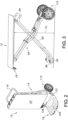
- FIG. 1 illustrates a multipurpose worktable 10.
- the multipurpose worktable 10 has a planar work surface 12 supported by a leg assembly 14.
- FIG. 1 illustrates the worktable 10 in an extended position in which the leg assembly 14 is extended to support the work surface 12 as a worktable for a user, e.g., as a miter saw compatible work surface.
- the multipurpose worktable 10 may include one or more storage support interfaces 18 configured to receive a complementary bracket to store items, such as tools or accessories, coupled to the work surface 12.
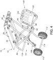
- FIG. 2 illustrates the multipurpose worktable 10 in a collapsed position in which the leg assembly 14 is folded into a collapsed position, e.g., to minimize the size of the multipurpose worktable 10 for storage.
- the multipurpose worktable 10 may include a platform 16 coupled to the leg assembly 14 so that the multipurpose worktable 10 transforms into a transport dolly in the collapsed position (illustrated in FIG. 2 and described in further detail below).
- the work surface 12 may include an upper surface 20, a lower surface 22.
- the upper surface 20 may be a planar surface forming a planar work area for a user.
- the lower surface 22 may be a planar surface, and the lower surface 22 may be generally parallel to the upper surface 20.
- the work surface 12 may have one or more side surfaces 24 extending between the upper surface 20 to the lower surface 22 around a perimeter of the work surface 12. For instance, when the work surface 12 has a generally rectangular perimeter shape as illustrated in FIGS.
- the side surfaces 24 may extend along a first side 26, second side 28, third side 30, and fourth side 32, whereby the first side 26 and second side 28 are generally parallel to each other and the third side 30 and the fourth side 32 are generally parallel to each other.
- the first side 26 and second side 28 may alternatively be described as a "first end” and a "second end" of the work surface 12 when describing the relatively positioning of the leg assembly 14 to the work surface 12.
- the work surface 12 may have one or a plurality of receptacles 34 configured to receive a fastener (not shown).
- a plurality of receptacles 34 may be present on the lower surface 22 of the work surface 12.
- the receptacles 34 may be spaced inward from and parallel to the sides 26, 28, 30, 32.
- the receptacles 34 may enable a user to couple one or more accessories to the work surface 12, e.g., by inserting a fastener into a receptacle.
- one or more tools or storage accessories may be coupled to the work surface 12 by utilizing the receptacles 34, such as saw tools, e.g., a miter saw or other saw, and/or storage accessories, such as storage bins, storage hooks, etc.
- saw tools e.g., a miter saw or other saw
- storage accessories such as storage bins, storage hooks, etc.
- a storage support interface 18 may be coupled to the work surface 12.
- the storage support interface 18 may provide storage for tools and/or accessories coupled to the work surface 12, enhancing accessibility for the user.
- the storage support interface 18 may be coupled to the work surface 12 by fastening the storage support interface 18 with one or more fasteners (not shown) to the receptacle(s) 34 described above.
- the storage support interface 18 may be repositionable relative to the work surface 12. In other words, the user may choose a convenient or desired position for the storage support interface 18 relative to the work surface 12, e.g., along any of the sides 26, 28, 30, 32.
- the storage support interface 18 may have a body 40 having a coupling portion 42 and a storage portion 44.
- the coupling portion 42 may extend along an upper side of the storage support interface 18, and may extend, e.g., in a horizontal plane.
- One or more openings 46 extend through the coupling portion 42 and are each configured to receive a fastener therein.
- the planar coupling portion 42 may be aligned with the support structure (e.g., the lower surface 22 as shown in FIG. 4 ) and fasteners may be inserted through the openings 46 to fasten to the support structure. While FIG. 4 illustrates the storage support interface 18 coupled to the work surface 12, the present invention contemplates coupling the storage support interface 18 to any desired support structure, particularly any horizontal planar support structure compatible with the coupling portion 42.
- the storage portion 44 of the storage support interface 18 may include one or more mounts 50 configured to receive a complementary bracket (not shown).
- each mount 50 may include a first angled support 52 and a second angled support 54 which angle toward each other in a downward extending direction.
- Each of the first angled support 52 and the second angled support 54 may have a projection portion 56 projecting outward from a planar face 60 (also referred to as a planar surface) of the mount 50.
- the first angled support 52 and the second angled support 54 may each have a retaining portion 58.
- the retaining portion 58 may be curved or bent inward toward the planar face 60.
- first angled support 52 and the second angled support 54 may be curved or bent toward each other so as to form a receiving space 62 therein.
- an opening 64 may be formed between the first angled support 52 and the second angled support 54 at a lower side of each mount 50. The opening 64 may communicate or extend from the receiving space 62 so that the bracket may be supported in the receiving space 62 and may extend through the opening 64.
- the storage portion 44 may further include one or more hooks 66.
- one or more hooks 66 may be provided between each mount 50.
- the storage portion 44 may include a bottom section 68 extending below the mounts 50, and one or more lower hooks 66a may extend from the bottom section 68.
- the storage portion 44 may include a top section 70 extending above the mounts 50, e.g., connecting the mounts 50 together, and one or more upper hooks 66b may extend from the top section 70.
- the bottom section 68 and the top section 70 may be coplanar with the planar face 60 of the mount(s) 50.
- the storage portion 44 may further include one or more fastener openings 72 similar to the fastener openings 46 of the coupling portion 42.
- the storage support interface 18 may be coupled to a support structure in a variety of orientations or planes.
- the storage support interface 18 may be integrally formed from one piece of material.
- the storage support interface may be integrally formed from a single piece of metal, e.g., bent or stamped metal to form the structures of the storage support interface 18.
- the coupling portion 42 and the storage section 44 may be formed from the single piece of material and optionally bent along an axis 74.
- the coupling portion 42 and a plane of the storage section 44 may be generally perpendicular to each other, e.g., to fit along an edge of the work surface 12.
- the storage portion 44 may include one or more negative spaces 76 where the material of the storage support interface 18 is bent out of the plane of the planar space 60, top section 70 and bottom section 68, e.g., to form one of the angled supports 52, 52 or hooks 66.
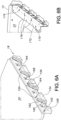
- FIGS. 6A-6B illustrate another storage support interface 18 of the present invention.
- One or more storage accessory rails 150 may be coupled to the work surface 12.
- two storage accessory rails 150 may be coupled to the work surface 12, e.g., along a side edge 26 or 28 of the work surface 12.
- a mounting bracket 170 may be provided to couple the storage accessory rail 150 to the work surface 12.
- a base section 172 of the mounting bracket 170 may extend coplanar with the bottom surface 22 of the work surface 12 and be coupled thereto, e.g., with fasteners.
- a rail coupling surface 174 may extend generally downward from the base section 172 and may be provided with fastener openings 176 to receive a fastener therethrough to couple the storage accessory rail 150.
- the rail coupling surface 174 may extend generally coplanar with the side surface 26 or 26 from which the storage accessory rail 150 extends.
- the storage accessory rail 150 may include a generally planar portion 152, a central protrusion 154 protruding outward relative to the planar portion 152, a first side protrusion 156 disposed at a first side of the rail 150, and a second side protrusion 158 at a second side of the rail 150.
- Each of the protrusions may alternatively be referred to as "cleats.”
- a slot 162 may be formed through the planar portion 152 along one or more edges of each cleat, e.g., to permit engagement of a complementary bracket (not shown).
- each cleat may include an overhanging portion 160 along one or more edges thereof, e.g., along the slot(s) 162, to form a receiving space between the generally planar portion 152 and the overhanging portion 160 to hold a bracket therein.
- a mount may be formed between two adjacent protrusions, e.g., the central protrusion 154 and the first side protrusion 156, with a bracket receiving space 164 formed along the generally planar portion 152 therebetween.
- One or more fastener openings 168 may be formed through the generally planar portion 152 to receive a fastener for fastening the rail 150 to the mounting bracket 170.
- each of the first side protrusion 156 and the second side protrusion 158 may be formed as generally one half of the central protrusion 154.
- a full cleat may be formed by the first and second side protrusions 156, 158 of the adjacent rails 150, as illustrated in FIG. 6A .
- Each of the cleats may have one or more angled sides that extend at an angle relative to a longitudinal axis of the rail 150 and a vertical axis of the rail 150.
- each of the cleats may further include a vertical side or edge disposed below the angled surface, e.g., so the bracket receiving space 164 forms generally a Y-shape.
- the leg assembly 14 may include a first leg 80 and a second leg 94.
- Each of the legs of the leg assembly may be formed from any suitable material and shape, such as plastic or metal hollow or solid rods.
- the legs may be formed from hollow metal tubes.
- a pair of first legs 80 may be generally parallel
- a pair of second legs 94 may be generally parallel to each other.
- the second leg 94 may include a first elongated section 96 and a second elongated section 98.
- the first elongated section 96 may be coupled to the work surface 12 at an upper end of the first elongated section 96.
- a pivotable coupling 100 may be provided to pivotably couple the upper end of the first elongated section 96 to the lower surface 22 of the work surface 12.
- the second elongated section 98 may be coupled to the first elongated section 96 at an upper end and a foot section 102 at a lower end.
- a pivotable coupling 104 may be provided between the second elongated section 98 and the first elongated section 96 to enable pivoting of the second elongated section 98 relative to the first elongated section 96, e.g. to fold the work table into the collapsed position.
- the second elongated section 96 may further include a pivotable coupling 106 to couple the second elongated section 96 with the elongated section 82 of the first leg 80.
- the second leg 94 may extend in a transverse, e.g., opposite, direction relative to the first leg 80 and the work surface 12, e.g., such that the elongated section 82 of the first leg 80 and the second leg 94 may form an X shape or transverse arrangement relative to each other in the extended position (see FIGS. 1 and 4 ).
- the first leg 80 and the first elongated section 96 of the second leg 94 may extend generally parallel to each other and parallel to the lower surface 22 of the work surface 12.
- the second elongated section 98 may extend generally parallel to the first elongated section 96.
- the foot section 86 and the foot section 102 may be disposed generally adjacent to each other in the collapsed position of the multipurpose worktable 10 (see FIG. 2 ).
- the leg assembly 14 may be provided with a locking mechanism including a foot lever 130 configured to enable a user to lock the first leg 80 and second leg 94 in either the extended position or collapsed position relative to each other.
- the foot lever 130 may be coupled with the second leg 94 as illustrated. Engagement of the foot lever 130 may enable locking of the locking mechanism, and disengagement of the foot lever 130 may unlock the locking mechanism to enable a user to transition between the extended and collapsed positions.
- the work surface 12 may extend a height H1 above the floor surface when the multipurpose worktable 10 is in the extended position.
- the height H1 may be in a range from about 30 inches to about 36 inches, such as from about 32 inches to about 33 inches, for instance, about 33.6 inches.
- the foot section 102 of the second leg 94 may include a wheel assembly 110.
- the wheel assembly 110 may include a wheel 112 and an axle 114.
- two wheels 112 may be provided and may be coupled by the axle 114.
- the wheel assembly 110 may enable the worktable 10 to be easily transported by rolling along the wheels 112.
- a handle 116 may be removably coupled to the coupling section 84 a platform 120 may be removably coupled to the foot section 86.
- the platform 120 may include a platform frame 122 configured to couple with the foot section 86, e.g., by insertion, and a platform body 124.
- the platform body 124 may have a generally rectangular shape to provide a surface area 126 for supporting one or more objects, such as storage containers.
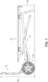
- the platform 120 When the worktable 10 is in the collapsed position, the platform 120 may extend generally perpendicular to the work surface 12, forming a support region 128 between the work surface 12 and the platform surface area 126. In this manner, the platform 120 can enable the multipurpose worktable 10 to function as a transport dolly in the collapsed position, as illustrated in FIG. 2 , for transportation of items supported by the platform 120 and the work surface 12 in the support region 128.
- the multipurpose worktable 10 of the present invention may stand in an upright position (with the work surface oriented vertically) on its own, i.e., without requiring external support, when it is in the collapsed or storage position.
- the multipurpose worktable 10 may also be referred to as a multipurpose transport dolly or hand truck, as shown in FIG. 2 and described above.
- the leg assembly 14 may form a frame for the transport dolly.
- the work surface 12 may form a support surface for the transport dolly.
- the collapsed position of the leg assembly 14 described above may also be referred to as a storage position for the leg assembly 14 or frame.
- the wheel assembly 110 and the platform frame 122 may support the multipurpose worktable 10 on the ground or floor.
- the multipurpose worktable 10 may further be used in a horizontal orientation when in the collapsed position, e.g., for storage of raw materials or to keep materials off of the ground, to place taller work items (cabinetry, doors, etc.) on while performing work.
- the surface 20 may have a height H2 of about 10 inches to about 15 inches, such as about 12.5 inches, from the floor. For instance, a lower height could benefit the operator to have a more advantageous or more appropriate work height depending on what the user's current application is.
- the platform 18 may extend a height H3 above the floor.
- the height H3 may be in a range from about 24 inches to about 30 inches.
- a typical height for a tonneau (i.e., truck bed) cover is approximately 18 inches to 22 inches.
- a multipurpose worktable comprising: a work surface, a leg assembly, at least one wheel, and a platform.
- the work surface has an upper surface, a lower surface, and at least one side surface extending between the upper surface and lower surface.
- the leg assembly is coupled to the lower surface and is configured to transition between an extended position and a collapsed position.
- the at least one wheel is coupled to the leg assembly, and the platform is coupled to the leg assembly. In the collapsed position, an upper surface of the platform extends generally perpendicular relative to the upper surface of the work surface.
- the multipurpose worktable of any one or more of the embodiments wherein in the collapsed position, the multipurpose worktable is configured to stand self-supported in a vertical orientation having the upper surface extending vertically and in a horizontal orientation having the upper surface extending horizontally.
- the multipurpose worktable of any one or more of the embodiments the upper surface having a height of less than about 15 inches from a ground surface when the multipurpose worktable is in the horizontal orientation of the collapsed position.
- the multipurpose worktable of any one or more of the embodiments further comprising a storage support interface coupled to the work surface, the storage support interface comprising at least one mount configured to receive a complementary bracket.
- each mount comprising two protrusions and a bracket receiving space is formed between the two protrusions.
- a multipurpose transport dolly comprising: a frame; a platform coupled to the frame; a support surface extending generally perpendicular to the platform and supported by the frame; a wheel assembly coupled to the frame; and a handle coupled to the frame.
- the frame comprises a pair of legs configured to transition between a storage position and an extended position. In the extended position, the pair of legs supports the support surface and the support surface forms a worktable.
- a storage support interface comprising: a body having a planar surface and one or more mounts; each mount including: a first angled support having a projection portion projecting outward from the planar surface and a retaining portion extending at an angle relative to the projection portion, and a second angled support having a projection portion projecting outward from the planar surface and a retaining portion extending at an angle relative to the projection portion.
- the first angled support and the second angled support are angled toward each other in a downward extending direction.
- An opening is formed between a lower end of the first angled support and a lower end of the second angled support.
- Each mount has a Y-shaped bracket receiving section configured to receive a Y-shaped bracket therein.
- the body further includes an opening between each mount, and a coupling section formed in the body above or below the one or more mounts.
- the storage support interface of any one or more of the embodiments wherein the storage support interface is formed from a single piece of material, and the opening between each mount includes negative space formed by bending the first angled support and the second angled support out of the plane of the planar surface.
- the storage support interface of any one or more of the embodiments further including at least one hook above or below the opening between each mount, the hook projecting at an angle relative to the planar surface.
Landscapes
- Engineering & Computer Science (AREA)
- Mechanical Engineering (AREA)
- Chemical & Material Sciences (AREA)
- Combustion & Propulsion (AREA)
- Transportation (AREA)
- Ladders (AREA)
- Handcart (AREA)
Applications Claiming Priority (1)
| Application Number | Priority Date | Filing Date | Title |
|---|---|---|---|
| US18/379,428 US20250121866A1 (en) | 2023-10-12 | 2023-10-12 | Multipurpose worktable |
Publications (2)
| Publication Number | Publication Date |
|---|---|
| EP4537992A2 true EP4537992A2 (de) | 2025-04-16 |
| EP4537992A3 EP4537992A3 (de) | 2025-09-03 |
Family
ID=93014989
Family Applications (1)
| Application Number | Title | Priority Date | Filing Date |
|---|---|---|---|
| EP24205112.6A Pending EP4537992A3 (de) | 2023-10-12 | 2024-10-07 | Mehrzweckarbeitstisch |
Country Status (5)
| Country | Link |
|---|---|
| US (1) | US20250121866A1 (de) |
| EP (1) | EP4537992A3 (de) |
| CN (1) | CN119817925A (de) |
| AU (1) | AU2024227098A1 (de) |
| CA (1) | CA3247513A1 (de) |
Family Cites Families (16)
| Publication number | Priority date | Publication date | Assignee | Title |
|---|---|---|---|---|
| US4372450A (en) * | 1981-12-07 | 1983-02-08 | Basic Line, Inc. | Hanging racks |
| US5797612A (en) * | 1995-03-24 | 1998-08-25 | Buccioni; Aldo | Sports equipment carrier |
| US6880835B2 (en) * | 2003-04-11 | 2005-04-19 | Sylmark Holdings Limited | Combination hand truck, step ladder and dolly |
| US7588255B2 (en) * | 2004-11-10 | 2009-09-15 | Zag Industries, Ltd. | Collapsible clamping work table |
| US7255355B2 (en) * | 2005-01-03 | 2007-08-14 | Mk Diamond Products, Inc. | Portable collapsible stand |
| JP4954680B2 (ja) * | 2006-11-21 | 2012-06-20 | 株式会社マキタ | 電動工具用作業台 |
| US9149926B2 (en) * | 2011-06-17 | 2015-10-06 | Rexon Industrial Corp., Ltd. | Collapsible stand |
| FR2987591B1 (fr) * | 2012-03-01 | 2018-02-02 | Psa Automobiles Sa. | Chariot de transport transformable a paire de jambes rabattables et roues rabattables simultanement |
| CA3065702A1 (en) * | 2019-12-20 | 2021-06-20 | 2446914 Ontario Inc. | Collapsible support |
| US11890744B2 (en) * | 2020-07-31 | 2024-02-06 | Techtronic Cordless Gp | Workbench-hand truck assembly |
| EP4029657A1 (de) * | 2020-08-07 | 2022-07-20 | Techtronic Cordless GP | Modulares aufbewahrungssystem |
| EP4232243A4 (de) * | 2020-10-26 | 2024-12-11 | Milwaukee Electric Tool Corporation | Kupplungsmechanismus für ein versorgungsmodul |
| EP4323154A4 (de) * | 2021-04-13 | 2025-03-26 | Milwaukee Electric Tool Corporation | Kopplungsplattform für ein versorgungsmodul |
| CA3179150A1 (en) * | 2021-10-18 | 2023-04-18 | Techtronic Cordless Gp | Modular accessories and storage systems |
| US20240083480A1 (en) * | 2022-06-18 | 2024-03-14 | U-Kart Systems, LLC | Transportation system and methods of using thereof |
| US11926034B1 (en) * | 2022-10-18 | 2024-03-12 | Jianyong Yu | Tool hanger |
-
2023
- 2023-10-12 US US18/379,428 patent/US20250121866A1/en active Pending
-
2024
- 2024-10-03 CA CA3247513A patent/CA3247513A1/en active Pending
- 2024-10-04 AU AU2024227098A patent/AU2024227098A1/en active Pending
- 2024-10-07 EP EP24205112.6A patent/EP4537992A3/de active Pending
- 2024-10-11 CN CN202411416685.8A patent/CN119817925A/zh active Pending
Also Published As
| Publication number | Publication date |
|---|---|
| CN119817925A (zh) | 2025-04-15 |
| AU2024227098A1 (en) | 2025-05-01 |
| EP4537992A3 (de) | 2025-09-03 |
| US20250121866A1 (en) | 2025-04-17 |
| CA3247513A1 (en) | 2025-06-02 |
Similar Documents
| Publication | Publication Date | Title |
|---|---|---|
| US12036660B2 (en) | Modular storage system | |
| US6086073A (en) | Portable work center | |
| US7874451B2 (en) | Container assembly for use on planar surfaces of varying slopes | |
| US7066476B2 (en) | Side attachable cover/seat for a cart carrying box | |
| US7331454B2 (en) | Wheeled tool bag | |
| US20220117393A1 (en) | Storage system | |
| US7988160B2 (en) | Cleaning cart | |
| US8678227B2 (en) | Leg assembly | |
| US7263932B2 (en) | Personal table | |
| US20230013573A1 (en) | Portable food preparation apparatus | |
| US8826829B2 (en) | Foldable work bench station | |
| US9943954B2 (en) | Workbench arrangement adapted to be in part supportable by a wheelie bin | |
| US11673510B1 (en) | Portable cargo carrying assembly | |
| US7914018B1 (en) | Furniture cart | |
| US20240139932A1 (en) | Modular, multi-rail sawhorse with pivoting legs | |
| US5713404A (en) | Folding work center | |
| US20260130496A1 (en) | Work table | |
| US20250121866A1 (en) | Multipurpose worktable | |
| US20040112258A1 (en) | Fold up workshop | |
| US8167151B2 (en) | Forkable base stand | |
| US20050274301A1 (en) | Collapsible table and a method for collapsing a table | |
| US20260070210A1 (en) | Modular Tool Storage System for Aerial Lift Platforms and Method for the Same | |
| US20110148264A1 (en) | Base stand with drawer | |
| US12234689B2 (en) | Ladder-mounted ledge for holding tools and materials | |
| US20250000250A1 (en) | Collapsible table |
Legal Events
| Date | Code | Title | Description |
|---|---|---|---|
| PUAI | Public reference made under article 153(3) epc to a published international application that has entered the european phase |
Free format text: ORIGINAL CODE: 0009012 |
|
| STAA | Information on the status of an ep patent application or granted ep patent |
Free format text: STATUS: THE APPLICATION HAS BEEN PUBLISHED |
|
| AK | Designated contracting states |
Kind code of ref document: A2 Designated state(s): AL AT BE BG CH CY CZ DE DK EE ES FI FR GB GR HR HU IE IS IT LI LT LU LV MC ME MK MT NL NO PL PT RO RS SE SI SK SM TR |
|
| PUAL | Search report despatched |
Free format text: ORIGINAL CODE: 0009013 |
|
| AK | Designated contracting states |
Kind code of ref document: A3 Designated state(s): AL AT BE BG CH CY CZ DE DK EE ES FI FR GB GR HR HU IE IS IT LI LT LU LV MC ME MK MT NL NO PL PT RO RS SE SI SK SM TR |
|
| RIC1 | Information provided on ipc code assigned before grant |
Ipc: B25H 1/04 20060101AFI20250729BHEP |
|
| STAA | Information on the status of an ep patent application or granted ep patent |
Free format text: STATUS: REQUEST FOR EXAMINATION WAS MADE |
|
| 17P | Request for examination filed |
Effective date: 20260303 |