EP4537960A1 - A method for adjusting the orientation of a cutting edge of a turning tool - Google Patents
A method for adjusting the orientation of a cutting edge of a turning tool Download PDFInfo
- Publication number
- EP4537960A1 EP4537960A1 EP23203551.9A EP23203551A EP4537960A1 EP 4537960 A1 EP4537960 A1 EP 4537960A1 EP 23203551 A EP23203551 A EP 23203551A EP 4537960 A1 EP4537960 A1 EP 4537960A1
- Authority
- EP
- European Patent Office
- Prior art keywords
- misalignment
- topography
- machined surface
- workpiece
- orientation
- Prior art date
- Legal status (The legal status is an assumption and is not a legal conclusion. Google has not performed a legal analysis and makes no representation as to the accuracy of the status listed.)
- Granted
Links
Images


Classifications
-
- B—PERFORMING OPERATIONS; TRANSPORTING
- B23—MACHINE TOOLS; METAL-WORKING NOT OTHERWISE PROVIDED FOR
- B23B—TURNING; BORING
- B23B1/00—Methods for turning or working essentially requiring the use of turning-machines; Use of auxiliary equipment in connection with such methods
-
- G—PHYSICS
- G05—CONTROLLING; REGULATING
- G05B—CONTROL OR REGULATING SYSTEMS IN GENERAL; FUNCTIONAL ELEMENTS OF SUCH SYSTEMS; MONITORING OR TESTING ARRANGEMENTS FOR SUCH SYSTEMS OR ELEMENTS
- G05B19/00—Program-control systems
- G05B19/02—Program-control systems electric
- G05B19/18—Numerical control [NC], i.e. automatically operating machines, in particular machine tools, e.g. in a manufacturing environment, so as to execute positioning, movement or co-ordinated operations by means of program data in numerical form
- G05B19/402—Numerical control [NC], i.e. automatically operating machines, in particular machine tools, e.g. in a manufacturing environment, so as to execute positioning, movement or co-ordinated operations by means of program data in numerical form characterised by control arrangements for positioning, e.g. centring a tool relative to a hole in the workpiece, additional detection means to correct position
-
- B—PERFORMING OPERATIONS; TRANSPORTING
- B23—MACHINE TOOLS; METAL-WORKING NOT OTHERWISE PROVIDED FOR
- B23B—TURNING; BORING
- B23B2200/00—Details of cutting inserts
- B23B2200/20—Top or side views of the cutting edge
- B23B2200/208—Top or side views of the cutting edge with wiper, i.e. an auxiliary cutting edge to improve surface finish
-
- B—PERFORMING OPERATIONS; TRANSPORTING
- B23—MACHINE TOOLS; METAL-WORKING NOT OTHERWISE PROVIDED FOR
- B23B—TURNING; BORING
- B23B2270/00—Details of turning, boring or drilling machines, processes or tools not otherwise provided for
- B23B2270/48—Measuring or detecting
-
- B—PERFORMING OPERATIONS; TRANSPORTING
- B23—MACHINE TOOLS; METAL-WORKING NOT OTHERWISE PROVIDED FOR
- B23B—TURNING; BORING
- B23B27/00—Tools for turning or boring machines; Tools of a similar kind in general; Accessories therefor
- B23B27/14—Cutting tools of which the bits or tips or cutting inserts are of special material
- B23B27/141—Specially shaped plate-like cutting inserts, i.e. length greater or equal to width, width greater than or equal to thickness
- B23B27/145—Specially shaped plate-like cutting inserts, i.e. length greater or equal to width, width greater than or equal to thickness characterised by having a special shape
Definitions
- the invention relates to metal cutting, in particular turning.
- Turning is a common metal cutting operation wherein a turning tool is used to cut a rotating workpiece.
- Such turning tool often includes a cutting insert, for example made from cemented carbide.
- the cutting insert is often mounted in a seat arranged in the turning tool, for example using a screw or some other fastening mechanism.
- Some cutting inserts have cutting edges that include not only a nose cutting edge, but also a so called “wiper” edge that may result in a better surface finish by smoothing out the scallops in the machined surface.
- a wiper edge usually consists of one or more large radiused, often nearly straight, edge segments following the nose cutting edge and that "wipes" the surface behind the nose cutting edge.
- the invention relates to a method for adjusting the orientation of a cutting edge of a turning tool with respect to a workpiece, wherein the cutting edge includes a wiper edge, and wherein the method comprises the steps of:
- the cutting edge of the turning tool can be correctly oriented with respect to the workpiece, such that an improved surface finish is achieved.
- the cutting insert When mounted in the seat, the cutting insert obtains a fixed position in which the exact location and orientation of the cutting edge, and in particular the wiper edge, with respect to the turning tool body may not be completely known, but depend on various parameters, such as random variations or defects in the geometry of the cutting insert. Moreover, additional uncertain parameters related to the machine tool, or the setup of the workpiece, may affect the actual orientation of the cutting edge with respect to the machined surface. The inventors have found that such variations, and the negative effects of such variations, are often greater than usually assumed.
- the inventors have found that the orientation of the wiper edge with respect to the workpiece surface is detrimental for achieving a good surface finish, and that a misalignment of the wiper edge with respect to the workpiece surface may be determined by measuring and studying the topography of the machined surface.
- the cutting edge may be a part of an exchangeable and/or indexable cutting insert arranged in a seat of the turning tool. It is also envisaged though, that the cutting edge is an integral portion of the turning tool.
- Measuring the topography of the machined surface may involve the use of a measuring device, such as a perthometer or a profilometer, for example using non-contact techniques, e.g., based on optical methods, or a stylus contacting the surface.
- a measuring device such as a perthometer or a profilometer
- non-contact techniques e.g., based on optical methods, or a stylus contacting the surface.
- topography of a machined surface should be understood as any measure that characterizes the geometry of the machined surface and that is dependent on a misalignment of the wiper edge with respect to the machined surface.
- Adjusting the orientation of the cutting edge may be done in many different ways.
- the adjustment may involve adjusting the orientation of the turning tool, but may also involve adjustment of only a portion of the turning tool that includes the cutting edge.
- the turning tool may include a cutting head that holds the cutting insert and that is moveable with respect to a tool body of the turning tool.
- the cutting head may be slightly rotatable or tiltable such that the orientation of the cutting edge with respect to the workpiece can be changed.
- the cutting head may include a locking arrangement that prevents movement of the cutting head when in a locked state.
- the turning tool may also include a control device that can be used to change the position of the cutting head when the locking arrangement is in an unlocked state.
- a visible scale is arranged on the cutting head and tool body, such that a position of the cutting head with respect to the tool body can be readily assessed.
- the misalignment is defined by an angle of misalignment that corresponds to the angle that the wiper edge forms to the machined surface, and wherein an angle of zero degrees corresponds to no misalignment.
- the wiper edge may not be formed by a completely straight edge, but by one or more large radius segments. However, for the purposes of this disclosure, the wiper edge may be considered as, i.e., approximated by, a straight edge forming a specific angle with respect to the machined surface. If the wiper edge is parallel with the machined surface, i.e., if the angle is zero, there is no misalignment of the wiper edge with respect to the surface.
- the topography may correspond to a profile of the machined surface.
- a profile of a surface is generally understood as a contour of the surface in a section, in this case preferably a section parallel with the feed direction of the turning tool.
- the profile may be the raw profile as directly obtained by the measuring device, e.g., profilometer, but it may also be a filtered profile, in which variations that are not relevant for the determination of misalignment of the wiper edge have been removed.
- the profile may be a primary profile (P-profile) in which the shortest wavelength components have been removed from the measured profile by low-pass filtering, or a roughness profile (R-profile) wherein high-pass filtering has been applied to the P-profile to remove longer wavelength components such that the profile only includes the surface roughness.
- P-profile primary profile
- R-profile roughness profile
- the profile of a surface may be determined by a profilometer, for example.
- the profile includes multiple ridges extending from a nominal machined surface, wherein each ridge, in the feed direction, includes an ascending portion extending to a peak of the ridge from a valley located at the nominal machined surface between the ridge and a preceding ridge, followed by a descending portion extending from the peak of the ridge to a valley located at the nominal machined surface between the ridge and a following ridge, and wherein the misalignment of the wiper edge is determined based on the length and inclination of the ascending portions and/or the descending portions with respect to the nominal machined surface.
- the internal angle between the nominal machined surface and the longest one of the ascending portion and the descending portion is identified as the angle of misalignment.
- the misalignment of the wiper edge e.g., the angle of the wiper edge with respect to the machined surface, can be directly determined from the profile of the surface.
- the nominal machined surface should be understood as the surface without any ridges, which may correspond to the desired (intended) machined surface of the workpiece. Thus, in the profile, the nominal machined surface corresponds to a line including all the valleys.
- the valleys between the ridges are longer than the ascending and descending portions of the ridges (or if there are no ridges at all), this would indicate a wiper edge that is well aligned with respect to the machined surface, i.e., wherein the wiper edge is parallel to the machined surface.
- the wiper edge is to some extent misaligned, i.e., non-parallel with respect to the machined surface, and the misalignment would then correspond to the internal angle formed between the nominal machined surface and the ascending or descending portion, whichever is longest.
- the angle of misalignment is identified as negative if the descending portion is longer than the ascending portion, and positive if the ascending portion is longer than the descending portion.
- the topography may be defined by a parameter of the roughness of the surface, such as the average roughness Ra or the mean roughness depth Rz of a profile of the surface.
- the average roughness Ra is defined as an arithmetic average of profile height deviations from a mean line of the profile
- the mean roughness depth Rz is the average of maximum peak to valley heights of the profile.
- a misalignment can be identified simply by detecting a roughness that differs from the expected roughness, and an adjustment of the orientation of the cutting edge can be made accordingly.
- An identified parameter of the surface roughness that deviates from the expected value may not indicate in what direction the wiper edge is misaligned with respect to the workpiece. Therefore, in embodiments wherein a parameter of the surface roughness is used as a measure of the topography, multiple re-orientations of the cutting edge in different directions may be required to identify the optimal orientation of the cutting edge (the orientation wherein there is no misalignment of the wiper edge with respect to the machined surface).
- the method further includes, after measuring the first topography of the surface and before determining the misalignment, performing one or more times the steps of:
- multiple cuts using different orientations may not necessarily be a problem since many components are anyway machined in multiple passes, wherein a small amount of material is removed from the workpiece in each pass of the turning tool.
- This trial-and-error approach would, after multiple re-orientations of the cutting edge, make it possible to determine the misalignment of the wiper edge with respect to the surface, i.e., as the difference between the orientation that resulted in the first topography and the orientation that was found to result in an optimal comparative topography (or at least a comparative topography that is the result of a better aligned wiper edge than used to create the first topography). Based on this, the orientation of the cutting edge can be adjusted accordingly before the final pass(es) of the turning tool.
- the embodiments referred to above, involving analyzing either the geometry of the ridges in the profile or a parameter of the roughness, are based on assessment of one or more profiles of the surface, as measured for example by a profilometer or a similar measurement device. In other embodiments, other measures of the topography of the machined surface may be used.
- Figs. 1-3 illustrate a turning tool including a tool body 10 and a cutting insert 1 comprising a cutting edge 3.
- the cutting insert 1 is located on a cutting head 2 that is adjustably arranged with respect to the tool body 10.
- the cutting insert 1 is mounted in an insert seat on the cutting head 2 by means of a fastening screw 5.
- the cutting edge 3 includes a nose cutting edge 31 and a wiper edge 32, as illustrated in fig. 2 .
- the position of the cutting head 2 in relation to the tool body 10 can be adjusted by first unscrewing two locking screws 6 and then controlling an adjustment screw 7 that is arranged to contact a stop surface 8 formed inside a recess within the cutting head 2. Accordingly, the end portion of the adjustment screw 7 constitutes a stop that limits the position of the cutting head 2. Hence, when the adjustment screw 7 has been set at the desired position, and the cutting head rotated such that the stop surface 8 engages the front end of the adjustment screw 7, the locking screws 6 are used to fix the cutting head 2 such that the cutting head 2 is immovable with respect to the tool body 10.
- the position of the cutting head 2 with respect to the tool body 10 is visibly indicated by a scale 9 applied to the tool body 10 and cutting head 2.
- the scale 9 is a Vernier scale.
- the scale 10 is left out in fig. 3 and only shown in fig. 1 .
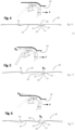
- the resulting topography of the machined surface caused by different orientations of the wiper edge 32 is illustrated in figs. 4-6 , wherein the orientation of the cutting insert 1 with respect to a machined surface 20 of a workpiece is illustrated in connection with respective resulting topographies of the machined surfaces 20, in this case illustrated as roughness profiles 30 of the machined surfaces 20.
- the roughness profiles 30 include grooves separated by ridges 21 caused by the feed of the tool during rotation of the workpiece. Random variations and noise have been removed by filtering the signals obtained from the measurement of the profile.
- Each of the profiles 30 includes multiple recurring ridges 21, each comprising, in a feed direction of the turning tool, an ascending portion 22, a descending portion 23 and a peak 24. Between the ridges, there are valleys 25 located at a nominal machined surface 26.
- the misalignment angle ⁇ w that the wiper edge forms to the surface being machined is used as a measure of the misalignment of the wiper edge with respect to the workpiece.
- the machined surface is rather smooth, wherein the valleys 25 are much wider than the ridges 21. The width of the ridges 21 will depend on the feed rate in relation to the length of the wiper edge.
- the wiper edge usually has a slight curvature (i.e., a large radius of curvature) which makes it impossible to obtain a surface that completely corresponds to the nominal machined surface 26.
- the wiper edge can be approximated by a straight line.
- misalignment angle ⁇ w When the misalignment angle ⁇ w is non-zero, a topography of the machined surface will arise that is less smooth, wherein the ridges 21 are asymmetric, higher, and wider. Therefore, by analyzing the topography of the machined surface, and in particular the profiles 30 shown in figs. 4-6 , it may be possible to estimate the misalignment angle ⁇ w , i.e., the misalignment of the wiper edge with respect to the machined surface.
- the misalignment angle ⁇ w is -5°, resulting in a roughness profile wherein the valleys 25 are short and the ridges 21 are asymmetric, having short ascending portions 22 but long descending portions 23.
- the misalignment angle ⁇ w is 5°, resulting in a roughness profile wherein the valleys 25 are short and the ridges 21 are asymmetric, having long ascending portions 22 but short descending portions 23.
- both the magnitude and the direction of misalignment can be determined from the roughness profile. Accordingly, it may therefore be possible to, based only on the profile 30, corresponding to the first topography, correctly adjust the orientation of the cutting edge for subsequent machining of the workpiece.
- the mean roughness depth Rz may be considered for the analysis.
- the mean roughness depth Rz is shown in figs. 4-6 as a single depth. However, this parameter is calculated as a mean for multiple ridges along the profile.
- fig. 7 is a flowchart indicating the steps of the method. Steps that are optional are illustrated by dashed lines.
- a surface of the workpiece is machined using the turning tool.
- the machining may for example correspond to a single pass of a longitudinal external turning operation, i.e., wherein the turning tool is moved along a direction parallel with the rotational axis of the workpiece while the cutting edge of the turning tool engages the exterior of the rotating workpiece.
- a first topography of the machined surface is measured. This can for example be achieved by using a profilometer to detect one or more profiles of the machined surface in a direction parallel with the rotational axis of the workpiece.
- the first topography considered may be the measured profile or a filtered profile, or a roughness parameter of such profile, such as Ra or Rz.
- the method would include, in a third step 703, adjusting the orientation of the cutting edge with respect to the workpiece, and, in a fourth step 704, machining the surface of the workpiece using the turning tool, and, in fifth step 705, measuring a comparative topography, i.e., the roughness parameter, of the newly machined surface.
- the direction and amount of adjustment of the orientation of the cutting edge in step 703 may be decided by an operator of the machine based on his or her knowledge and experience. Predefined guidelines of what adjustment to apply may also be used.
- the steps 703-705 of adjusting the orientation, machining the workpiece and measuring a comparative topography may be repeated as many times as required.
- the direction and amount of adjustment of the orientation of the cutting edge for such further adjustments is preferably based on the previously measured comparative topography and its relation to the first topography. For example, if the comparative topography indicates a better alignment of the wiper edge than the first topography, a further adjustment of the orientation of the cutting edge in the same direction may be applied.
- the misalignment of the cutting edge is determined (i.e., the misalignment of the cutting edge as originally oriented, resulting in the first topography).
- the misalignment may correspond to the difference between the cutting edge orientation that provided the first topography and the cutting edge orientation that was found to provide the most optimal comparative topography (e.g., the smallest roughness parameter).
- step 707 the orientation of the cutting edge with respect to the workpiece is adjusted based on the determined misalignment.
Landscapes
- Engineering & Computer Science (AREA)
- Human Computer Interaction (AREA)
- Manufacturing & Machinery (AREA)
- Physics & Mathematics (AREA)
- General Physics & Mathematics (AREA)
- Automation & Control Theory (AREA)
- Mechanical Engineering (AREA)
- Milling Processes (AREA)
Abstract
- machining (701) a surface of the workpiece (20) using the turning tool;
- measuring (702) a first topography of the machined surface;
- determining (706) a misalignment of the wiper edge (32) with respect to the surface based on the first topography of the machined surface; and
- adjusting (707) the orientation of the cutting edge (3) with respect to the workpiece (20) based on the misalignment.
Description
- The invention relates to metal cutting, in particular turning.
- Turning is a common metal cutting operation wherein a turning tool is used to cut a rotating workpiece. Such turning tool often includes a cutting insert, for example made from cemented carbide. The cutting insert is often mounted in a seat arranged in the turning tool, for example using a screw or some other fastening mechanism. Some cutting inserts have cutting edges that include not only a nose cutting edge, but also a so called "wiper" edge that may result in a better surface finish by smoothing out the scallops in the machined surface. A wiper edge usually consists of one or more large radiused, often nearly straight, edge segments following the nose cutting edge and that "wipes" the surface behind the nose cutting edge.
- Even if using a wiper cutting edge a machined surface may sometimes have a quality that is below expectations, for example with respect to surface roughness. One way to improve the surface roughness could be to reduce the feed rate. However, this would affect the productivity in a negative way.
- Accordingly, there is a need for turning solutions that provides a better control of the resulting quality of the machined surface and improve the machining results with maintained productivity.
- It is an object of the present invention to mitigate the shortcomings of the prior art and to provide methods for turning tools having a cutting edge that includes a wiper edge that results in improved surface finish of the machined surface.
- Thus, the invention relates to a method for adjusting the orientation of a cutting edge of a turning tool with respect to a workpiece, wherein the cutting edge includes a wiper edge, and wherein the method comprises the steps of:
- machining a surface of the workpiece using the turning tool;
- measuring a first topography of the machined surface;
- determining a misalignment of the wiper edge with respect to the surface based on the first topography of the machined surface;
- adjusting the orientation of the cutting edge with respect to the workpiece based on the misalignment.
- Thereby, the cutting edge of the turning tool can be correctly oriented with respect to the workpiece, such that an improved surface finish is achieved.
- When mounted in the seat, the cutting insert obtains a fixed position in which the exact location and orientation of the cutting edge, and in particular the wiper edge, with respect to the turning tool body may not be completely known, but depend on various parameters, such as random variations or defects in the geometry of the cutting insert. Moreover, additional uncertain parameters related to the machine tool, or the setup of the workpiece, may affect the actual orientation of the cutting edge with respect to the machined surface. The inventors have found that such variations, and the negative effects of such variations, are often greater than usually assumed. In particular, the inventors have found that the orientation of the wiper edge with respect to the workpiece surface is detrimental for achieving a good surface finish, and that a misalignment of the wiper edge with respect to the workpiece surface may be determined by measuring and studying the topography of the machined surface.
- The cutting edge may be a part of an exchangeable and/or indexable cutting insert arranged in a seat of the turning tool. It is also envisaged though, that the cutting edge is an integral portion of the turning tool.
- Measuring the topography of the machined surface may involve the use of a measuring device, such as a perthometer or a profilometer, for example using non-contact techniques, e.g., based on optical methods, or a stylus contacting the surface.
- The topography of a machined surface, as used herein, should be understood as any measure that characterizes the geometry of the machined surface and that is dependent on a misalignment of the wiper edge with respect to the machined surface.
- Adjusting the orientation of the cutting edge may be done in many different ways. For example, the adjustment may involve adjusting the orientation of the turning tool, but may also involve adjustment of only a portion of the turning tool that includes the cutting edge. For example, if the turning tool includes an exchangeable cutting insert, the adjustment may involve adjusting the orientation of the cutting insert within the seat in which it is mounted. Alternatively, the turning tool may include a cutting head that holds the cutting insert and that is moveable with respect to a tool body of the turning tool. For example, the cutting head may be slightly rotatable or tiltable such that the orientation of the cutting edge with respect to the workpiece can be changed. Preferably, the cutting head may include a locking arrangement that prevents movement of the cutting head when in a locked state. The turning tool may also include a control device that can be used to change the position of the cutting head when the locking arrangement is in an unlocked state. Preferably, a visible scale is arranged on the cutting head and tool body, such that a position of the cutting head with respect to the tool body can be readily assessed.
- According to some embodiments, the misalignment is defined by an angle of misalignment that corresponds to the angle that the wiper edge forms to the machined surface, and wherein an angle of zero degrees corresponds to no misalignment.
- As discussed, the wiper edge may not be formed by a completely straight edge, but by one or more large radius segments. However, for the purposes of this disclosure, the wiper edge may be considered as, i.e., approximated by, a straight edge forming a specific angle with respect to the machined surface. If the wiper edge is parallel with the machined surface, i.e., if the angle is zero, there is no misalignment of the wiper edge with respect to the surface.
- According to some embodiments, the topography may correspond to a profile of the machined surface. A profile of a surface is generally understood as a contour of the surface in a section, in this case preferably a section parallel with the feed direction of the turning tool. The profile may be the raw profile as directly obtained by the measuring device, e.g., profilometer, but it may also be a filtered profile, in which variations that are not relevant for the determination of misalignment of the wiper edge have been removed. For example, the profile may be a primary profile (P-profile) in which the shortest wavelength components have been removed from the measured profile by low-pass filtering, or a roughness profile (R-profile) wherein high-pass filtering has been applied to the P-profile to remove longer wavelength components such that the profile only includes the surface roughness. The profile of a surface may be determined by a profilometer, for example.
- According to some embodiments, the profile includes multiple ridges extending from a nominal machined surface, wherein each ridge, in the feed direction, includes an ascending portion extending to a peak of the ridge from a valley located at the nominal machined surface between the ridge and a preceding ridge, followed by a descending portion extending from the peak of the ridge to a valley located at the nominal machined surface between the ridge and a following ridge, and wherein the misalignment of the wiper edge is determined based on the length and inclination of the ascending portions and/or the descending portions with respect to the nominal machined surface. According to some embodiments, if at least one of the ascending portion and the descending portion of each ridge is longer than the adjacent valley, the internal angle between the nominal machined surface and the longest one of the ascending portion and the descending portion is identified as the angle of misalignment.
- Accordingly, the misalignment of the wiper edge, e.g., the angle of the wiper edge with respect to the machined surface, can be directly determined from the profile of the surface.
- The nominal machined surface should be understood as the surface without any ridges, which may correspond to the desired (intended) machined surface of the workpiece. Thus, in the profile, the nominal machined surface corresponds to a line including all the valleys.
- If the valleys between the ridges are longer than the ascending and descending portions of the ridges (or if there are no ridges at all), this would indicate a wiper edge that is well aligned with respect to the machined surface, i.e., wherein the wiper edge is parallel to the machined surface. However, if the ascending portion or the descending portion of the ridges are longer than the valleys, then the wiper edge is to some extent misaligned, i.e., non-parallel with respect to the machined surface, and the misalignment would then correspond to the internal angle formed between the nominal machined surface and the ascending or descending portion, whichever is longest.
- According to some embodiments, the angle of misalignment is identified as negative if the descending portion is longer than the ascending portion, and positive if the ascending portion is longer than the descending portion. Thus, it is also possible to determine the direction in which the wiper edge is misaligned with respect to the workpiece.
- According to some embodiments, the topography may be defined by a parameter of the roughness of the surface, such as the average roughness Ra or the mean roughness depth Rz of a profile of the surface. As well-known in the art, the average roughness Ra is defined as an arithmetic average of profile height deviations from a mean line of the profile, whereas the mean roughness depth Rz is the average of maximum peak to valley heights of the profile.
- If it is known what parameter of the roughness that could be expected with a perfectly aligned wiper edge, a misalignment can be identified simply by detecting a roughness that differs from the expected roughness, and an adjustment of the orientation of the cutting edge can be made accordingly. An identified parameter of the surface roughness that deviates from the expected value may not indicate in what direction the wiper edge is misaligned with respect to the workpiece. Therefore, in embodiments wherein a parameter of the surface roughness is used as a measure of the topography, multiple re-orientations of the cutting edge in different directions may be required to identify the optimal orientation of the cutting edge (the orientation wherein there is no misalignment of the wiper edge with respect to the machined surface). If the surface roughness that could be expected with a perfectly aligned wiper edge is unknown, the method may nevertheless be used and would involve multiple re-orientations of the cutting edge in different directions. Hence, according to some embodiments, the method further includes, after measuring the first topography of the surface and before determining the misalignment, performing one or more times the steps of:
- changing the orientation of the cutting edge with respect to the workpiece,
- machining a surface of the workpiece using the turning tool,
- measuring a comparative topography of the machined surface,
- Accordingly, this would require more than one, such as at least three, cuts before the correct orientation of the cutting edge is found. However, multiple cuts using different orientations may not necessarily be a problem since many components are anyway machined in multiple passes, wherein a small amount of material is removed from the workpiece in each pass of the turning tool.
- This trial-and-error approach would, after multiple re-orientations of the cutting edge, make it possible to determine the misalignment of the wiper edge with respect to the surface, i.e., as the difference between the orientation that resulted in the first topography and the orientation that was found to result in an optimal comparative topography (or at least a comparative topography that is the result of a better aligned wiper edge than used to create the first topography). Based on this, the orientation of the cutting edge can be adjusted accordingly before the final pass(es) of the turning tool.
- The embodiments referred to above, involving analyzing either the geometry of the ridges in the profile or a parameter of the roughness, are based on assessment of one or more profiles of the surface, as measured for example by a profilometer or a similar measurement device. In other embodiments, other measures of the topography of the machined surface may be used.
- The solution will now be described in more detail by means of exemplary embodiments and with reference to the accompanying drawings, in which:
-
Fig. 1 illustrates a turning tool that can be used in a method according to the invention. -
Fig. 2 is an enlarged view of the cutting insert mounted in a seat of the turning tool. -
Fig. 3 is a top view of the turning tool. -
Fig. 4 illustrates a machined surface of a workpiece and an orientation of a turning tool corresponding to no misalignment of the wiper edge. -
Fig. 5 illustrates a machined surface of a workpiece and an orientation of a turning tool corresponding to negative misalignment of the wiper edge. -
Fig. 6 illustrates a machined surface of a workpiece and an orientation of a turning tool corresponding to positive misalignment of the wiper edge. -
Fig. 7 is a flowchart illustrating a method according to the invention. - All the figures are schematic, not necessarily to scale, and generally only show parts which are necessary in order to elucidate the respective embodiments, whereas other parts may be omitted or merely suggested. Unless otherwise indicated, like reference numerals refer to like parts in different figures.
-
Figs. 1-3 illustrate a turning tool including atool body 10 and acutting insert 1 comprising acutting edge 3. The cuttinginsert 1 is located on a cuttinghead 2 that is adjustably arranged with respect to thetool body 10. The cuttinginsert 1 is mounted in an insert seat on the cuttinghead 2 by means of afastening screw 5. - The
cutting edge 3 includes anose cutting edge 31 and awiper edge 32, as illustrated infig. 2 . - In the illustrated embodiment, the position of the cutting
head 2 in relation to thetool body 10 can be adjusted by first unscrewing two lockingscrews 6 and then controlling anadjustment screw 7 that is arranged to contact astop surface 8 formed inside a recess within the cuttinghead 2. Accordingly, the end portion of theadjustment screw 7 constitutes a stop that limits the position of the cuttinghead 2. Hence, when theadjustment screw 7 has been set at the desired position, and the cutting head rotated such that thestop surface 8 engages the front end of theadjustment screw 7, the locking screws 6 are used to fix the cuttinghead 2 such that the cuttinghead 2 is immovable with respect to thetool body 10. - As a consequence of such adjustment, the orientation of the
cutting edge 3, and in particular the orientation of thewiper edge 32, with respect to the tool body is changed. In this way, when the turning tool is mounted to a machine tool and arranged for machining a workpiece, it is possible to adjust the orientation of the cutting edge, and in particular the orientation of the wiper edge, in relation to the workpiece surface to be machined. - The position of the cutting
head 2 with respect to thetool body 10 is visibly indicated by ascale 9 applied to thetool body 10 and cuttinghead 2. In the illustrated embodiment, thescale 9 is a Vernier scale. For clarity, thescale 10 is left out infig. 3 and only shown infig. 1 . - The resulting topography of the machined surface caused by different orientations of the
wiper edge 32 is illustrated infigs. 4-6 , wherein the orientation of the cuttinginsert 1 with respect to a machinedsurface 20 of a workpiece is illustrated in connection with respective resulting topographies of the machined surfaces 20, in this case illustrated as roughness profiles 30 of the machined surfaces 20. The roughness profiles 30 include grooves separated byridges 21 caused by the feed of the tool during rotation of the workpiece. Random variations and noise have been removed by filtering the signals obtained from the measurement of the profile. - Each of the
profiles 30 includes multiplerecurring ridges 21, each comprising, in a feed direction of the turning tool, an ascendingportion 22, a descendingportion 23 and apeak 24. Between the ridges, there arevalleys 25 located at a nominal machinedsurface 26. - In the illustrated embodiment, the misalignment angle θw that the wiper edge forms to the surface being machined is used as a measure of the misalignment of the wiper edge with respect to the workpiece. A misalignment angle θw equal to zero, illustrated in
fig. 4 , in which the wiper edge extends in parallel with the machined surface, corresponds to no misalignment. As seen in the resultingprofile 30 of the surface, illustrated infig. 4 , the machined surface is rather smooth, wherein thevalleys 25 are much wider than theridges 21. The width of theridges 21 will depend on the feed rate in relation to the length of the wiper edge. In practice, the wiper edge usually has a slight curvature (i.e., a large radius of curvature) which makes it impossible to obtain a surface that completely corresponds to the nominal machinedsurface 26. For the purposes of the present invention, though, and as illustrated in the figures, the wiper edge can be approximated by a straight line. Also, by using the solution according to this disclosure wherein the orientation of the cutting edge is adjusted, it could be beneficial to use a wiper edge with greater radius of curvature, i.e., closer to being straight, than what is conventionally used. Thus, if considering thewiper edge 32 in the illustrated embodiment as completely straight, the resultingridges 21 illustrated infig. 4 would be the result of a too short wiper edge and/or too great feed rate used when machining. A complete elimination of theridges 21 may not always be desirable, though, since this might require an unreasonably low feed rate and/or an extension of the wiper edge that would result in too great cutting forces. - When the misalignment angle θw is non-zero, a topography of the machined surface will arise that is less smooth, wherein the
ridges 21 are asymmetric, higher, and wider. Therefore, by analyzing the topography of the machined surface, and in particular theprofiles 30 shown infigs. 4-6 , it may be possible to estimate the misalignment angle θw, i.e., the misalignment of the wiper edge with respect to the machined surface. - In
fig. 5 , the misalignment angle θw is -5°, resulting in a roughness profile wherein thevalleys 25 are short and theridges 21 are asymmetric, having short ascendingportions 22 but long descendingportions 23. The internal angle θd formed between the descendingportions 23 and the nominal machinedsurface 26 corresponds to the negative misalignment angle θw between the wiper edge and the machinedsurface 20 of the workpiece. In other words, after determining that the descendingportion 23 is longer than the ascendingportion 22, it can be concluded that the misalignment angle θw = - θd. - In
fig. 6 , the misalignment angle θw is 5°, resulting in a roughness profile wherein thevalleys 25 are short and theridges 21 are asymmetric, having long ascendingportions 22 butshort descending portions 23. The internal angle θa formed between the ascendingportions 22 and the nominal machinedsurface 26 corresponds to the positive misalignment angle θw between the wiper edge and the machinedsurface 20 of the workpiece. In other words, after determining that the ascendingportion 22 is longer than the ascendingportion 23, it can be concluded that the misalignment angle θw = θa. - Hence, both the magnitude and the direction of misalignment can be determined from the roughness profile. Accordingly, it may therefore be possible to, based only on the
profile 30, corresponding to the first topography, correctly adjust the orientation of the cutting edge for subsequent machining of the workpiece. - A different approach that does not require detailed analysis of the profile but is based on a parameter of the roughness is also possible. Accordingly, such alternative approach may require a less complex analysis of the profile. On the other hand, it may require additional machining operations with different orientations of the cutting edge.
- For example, the mean roughness depth Rz may be considered for the analysis. For illustrative purposes, the mean roughness depth Rz is shown in
figs. 4-6 as a single depth. However, this parameter is calculated as a mean for multiple ridges along the profile. - By first measuring the mean roughness depth Rz of the profile (corresponding to the first topography), and thereafter adjusting the orientation of the cutting edge and machining the workpiece and measuring the mean roughness depth Rz again (corresponding to a comparative topography), it is possible to determine the misalignment of the wiper edge and adjust the orientation of the cutting edge accordingly, although it may require repeating the procedure multiple times.
- In the following, a method according to the invention will be described with reference to
fig. 7 which is a flowchart indicating the steps of the method. Steps that are optional are illustrated by dashed lines. - In a
first step 701, a surface of the workpiece is machined using the turning tool. The machining may for example correspond to a single pass of a longitudinal external turning operation, i.e., wherein the turning tool is moved along a direction parallel with the rotational axis of the workpiece while the cutting edge of the turning tool engages the exterior of the rotating workpiece. - In a
second step 702, a first topography of the machined surface is measured. This can for example be achieved by using a profilometer to detect one or more profiles of the machined surface in a direction parallel with the rotational axis of the workpiece. In such case, the first topography considered may be the measured profile or a filtered profile, or a roughness parameter of such profile, such as Ra or Rz. - If a roughness parameter is measured and considered as the first topography, and in particular if the roughness that would be obtainable with a perfectly aligned wiper edge is unknown, the method would include, in a
third step 703, adjusting the orientation of the cutting edge with respect to the workpiece, and, in afourth step 704, machining the surface of the workpiece using the turning tool, and, infifth step 705, measuring a comparative topography, i.e., the roughness parameter, of the newly machined surface. - The direction and amount of adjustment of the orientation of the cutting edge in
step 703 may be decided by an operator of the machine based on his or her knowledge and experience. Predefined guidelines of what adjustment to apply may also be used. The steps 703-705 of adjusting the orientation, machining the workpiece and measuring a comparative topography may be repeated as many times as required. The direction and amount of adjustment of the orientation of the cutting edge for such further adjustments is preferably based on the previously measured comparative topography and its relation to the first topography. For example, if the comparative topography indicates a better alignment of the wiper edge than the first topography, a further adjustment of the orientation of the cutting edge in the same direction may be applied. - In
step 706, the misalignment of the cutting edge is determined (i.e., the misalignment of the cutting edge as originally oriented, resulting in the first topography). With reference to the example in which a roughness parameter is considered as the topography, the misalignment may correspond to the difference between the cutting edge orientation that provided the first topography and the cutting edge orientation that was found to provide the most optimal comparative topography (e.g., the smallest roughness parameter). - In
step 707, the orientation of the cutting edge with respect to the workpiece is adjusted based on the determined misalignment. Hence, once again with reference to the example in which a roughness parameter is considered as the topography, no adjustment of the orientation of the cutting edge is required if the last used orientation was also the one that resulted in the smallest roughness parameter. - Although the description above contains a plurality of specificities, these should not be construed as limiting the scope of the concept described herein but as merely providing illustrations of some exemplifying embodiments of the described concept. It will be appreciated that the scope of the presently described concept fully encompasses other embodiments which may become obvious to those skilled in the art, and that the scope of the presently described concept is accordingly not to be limited.
Claims (9)
- A method for adjusting the orientation of a cutting edge (3) of a turning tool with respect to a workpiece (20), wherein the cutting edge (3) includes a wiper edge (32), and wherein the method comprises the steps of:- machining (701) a surface of the workpiece (20) using the turning tool;- measuring (702) a first topography of the machined surface;- determining (706) a misalignment of the wiper edge (32) with respect to the surface based on the first topography of the machined surface; and- adjusting (707) the orientation of the cutting edge (3) with respect to the workpiece (20) based on the misalignment.
- A method according to claim 1, wherein the misalignment is defined by an angle of misalignment (θw) that corresponds to the angle that the wiper edge forms to the machined surface, and wherein an angle of zero degrees corresponds to no misalignment.
- A method according to any of the previous claims, wherein the first topography corresponds to a profile (30) of the surface.
- A method according to claim 3, wherein the profile includes multiple ridges (21) extending from a nominal machined surface (26), wherein each ridge (21), in the feed direction (F), includes an ascending portion (22) extending to a peak (24) of the ridge (21) from a valley (25) located at the nominal machined surface (26) between the ridge (21) and a preceding ridge, followed by a descending portion (23) extending from the peak (24) of the ridge (21) to a valley located at the nominal machined surface (26) between the ridge (21) and a following ridge, and wherein the misalignment of the wiper edge (32) is determined based on the length and inclination of the ascending portions (22) and/or the descending portions (23) with respect to the nominal machined surface (26).
- A method according to claims 2 and 4, wherein, if at least one of the ascending portion and the descending portion of each ridge is longer than the adjacent valley, the internal angle (θa, θd) between the nominal machined surface and the longest one of the ascending portion and the descending portion is identified as the angle of misalignment (θw).
- A method according to claim 5, wherein the angle of misalignment (θw) is negative if the descending portion is longer than the ascending portion, and positive if the ascending portion is longer than the descending portion.
- A method according to any of the claims 1 or 2, wherein the first topography is defined by a parameter of the roughness of the surface.
- A method according to claim 7, wherein the parameter of the roughness of the surface is the average roughness Ra or the mean roughness depth Rz of a profile of the surface.
- A method according to any of the previous claims, wherein the method further includes, after measuring the first topography of the surface and before determining the misalignment, performing one or more times the steps of:- changing (703) the orientation of the cutting edge with respect to the workpiece;- machining (704) a surface of the workpiece using the turning tool; and- measuring (705) a comparative topography of the machined surface; and wherein the misalignment of the wiper edge is determined based on the difference between the first topography and the one or more comparative topographies.
Priority Applications (3)
| Application Number | Priority Date | Filing Date | Title |
|---|---|---|---|
| EP23203551.9A EP4537960B1 (en) | 2023-10-13 | 2023-10-13 | A method for adjusting the orientation of a cutting edge of a turning tool |
| CN202480058645.2A CN121843779A (en) | 2023-10-13 | 2024-09-13 | Method for adjusting the orientation of the cutting edge of a turning tool |
| PCT/EP2024/075601 WO2025078102A1 (en) | 2023-10-13 | 2024-09-13 | A method for adjusting the orientation of a cutting edge of a turning tool |
Applications Claiming Priority (1)
| Application Number | Priority Date | Filing Date | Title |
|---|---|---|---|
| EP23203551.9A EP4537960B1 (en) | 2023-10-13 | 2023-10-13 | A method for adjusting the orientation of a cutting edge of a turning tool |
Publications (3)
| Publication Number | Publication Date |
|---|---|
| EP4537960A1 true EP4537960A1 (en) | 2025-04-16 |
| EP4537960C0 EP4537960C0 (en) | 2026-04-08 |
| EP4537960B1 EP4537960B1 (en) | 2026-04-08 |
Family
ID=88413251
Family Applications (1)
| Application Number | Title | Priority Date | Filing Date |
|---|---|---|---|
| EP23203551.9A Active EP4537960B1 (en) | 2023-10-13 | 2023-10-13 | A method for adjusting the orientation of a cutting edge of a turning tool |
Country Status (3)
| Country | Link |
|---|---|
| EP (1) | EP4537960B1 (en) |
| CN (1) | CN121843779A (en) |
| WO (1) | WO2025078102A1 (en) |
Citations (4)
| Publication number | Priority date | Publication date | Assignee | Title |
|---|---|---|---|---|
| SU1219257A1 (en) * | 1984-06-29 | 1986-03-23 | Пензенский Политехнический Институт | Tool positioning method |
| JP2006136985A (en) * | 2004-11-12 | 2006-06-01 | Toyota Motor Corp | Finishing method of shaft |
| US8257149B2 (en) * | 2006-03-01 | 2012-09-04 | Felsomat Gmbh & Co. Kg | Method of producing rotationally symmetrical surfaces on a workpiece |
| US20210299806A1 (en) * | 2020-03-30 | 2021-09-30 | National University Corporation Tokai National Higher Education And Research System | Machining apparatus and cutting method |
-
2023
- 2023-10-13 EP EP23203551.9A patent/EP4537960B1/en active Active
-
2024
- 2024-09-13 CN CN202480058645.2A patent/CN121843779A/en active Pending
- 2024-09-13 WO PCT/EP2024/075601 patent/WO2025078102A1/en active Pending
Patent Citations (4)
| Publication number | Priority date | Publication date | Assignee | Title |
|---|---|---|---|---|
| SU1219257A1 (en) * | 1984-06-29 | 1986-03-23 | Пензенский Политехнический Институт | Tool positioning method |
| JP2006136985A (en) * | 2004-11-12 | 2006-06-01 | Toyota Motor Corp | Finishing method of shaft |
| US8257149B2 (en) * | 2006-03-01 | 2012-09-04 | Felsomat Gmbh & Co. Kg | Method of producing rotationally symmetrical surfaces on a workpiece |
| US20210299806A1 (en) * | 2020-03-30 | 2021-09-30 | National University Corporation Tokai National Higher Education And Research System | Machining apparatus and cutting method |
Also Published As
| Publication number | Publication date |
|---|---|
| EP4537960C0 (en) | 2026-04-08 |
| CN121843779A (en) | 2026-04-10 |
| WO2025078102A1 (en) | 2025-04-17 |
| EP4537960B1 (en) | 2026-04-08 |
Similar Documents
| Publication | Publication Date | Title |
|---|---|---|
| KR102616616B1 (en) | Method for deburring a gear blank | |
| US6877934B2 (en) | Milling head for thread whirling | |
| KR101845366B1 (en) | Insert and indexable rotary cutting tool | |
| EP3025812B1 (en) | Method for forming by metal cutting a circular groove | |
| US8807890B2 (en) | Face hob hypoid gear tooth top-land radius by common chamfer tool | |
| CN107025359B (en) | Calculation and test method for the difference of cutting behavior between the left and right cutting edges | |
| CN119159380B (en) | Gear machining equipment and method for detecting curved surface of gear machining machine tool | |
| EP4537960B1 (en) | A method for adjusting the orientation of a cutting edge of a turning tool | |
| CN106407622B (en) | A kind of steep-pitch thread turning cutting tool design method | |
| US11247280B2 (en) | Rotatable tool for forming by metal cutting a circular groove | |
| CN105555451B (en) | Contour gauge, measuring device equipped with contour gauge, and measuring method | |
| CN102632288A (en) | Milling cutter with adjustable finish machining face | |
| EP0638012B1 (en) | Method of truing and angling cutter blades by sharpening | |
| JP4857105B2 (en) | Polishing apparatus calibration method | |
| CN116160025B (en) | A new method for machining and testing end face grooves | |
| CN109955039B (en) | A method for machining large-diameter clamps with precision grooves | |
| CN113124811B (en) | Method for accurately controlling gear shaving cutter grinding parameters | |
| CN214418209U (en) | Comb tooth cutter clamp | |
| CN113887023A (en) | Weak rigidity characteristic inclined milling surface quality optimization method based on analytic force model | |
| CN113385984A (en) | Cutter radial run-out identification method, device, terminal and storage medium | |
| JP2939286B2 (en) | Grinding equipment | |
| CN216680571U (en) | Hobbing deburring structure | |
| CN223997485U (en) | Finish turning and tapping tool | |
| KR102209601B1 (en) | Milling cutters for continuous process of planes and chamfer | |
| CN119549814A (en) | A deep hole thread processing device and processing method thereof |
Legal Events
| Date | Code | Title | Description |
|---|---|---|---|
| PUAI | Public reference made under article 153(3) epc to a published international application that has entered the european phase |
Free format text: ORIGINAL CODE: 0009012 |
|
| STAA | Information on the status of an ep patent application or granted ep patent |
Free format text: STATUS: THE APPLICATION HAS BEEN PUBLISHED |
|
| AK | Designated contracting states |
Kind code of ref document: A1 Designated state(s): AL AT BE BG CH CY CZ DE DK EE ES FI FR GB GR HR HU IE IS IT LI LT LU LV MC ME MK MT NL NO PL PT RO RS SE SI SK SM TR |
|
| STAA | Information on the status of an ep patent application or granted ep patent |
Free format text: STATUS: REQUEST FOR EXAMINATION WAS MADE |
|
| 17P | Request for examination filed |
Effective date: 20251016 |
|
| GRAP | Despatch of communication of intention to grant a patent |
Free format text: ORIGINAL CODE: EPIDOSNIGR1 |
|
| STAA | Information on the status of an ep patent application or granted ep patent |
Free format text: STATUS: GRANT OF PATENT IS INTENDED |
|
| RIC1 | Information provided on ipc code assigned before grant |
Ipc: B23B 1/00 20060101AFI20251124BHEP Ipc: B23B 27/14 20060101ALI20251124BHEP Ipc: G05B 19/402 20060101ALI20251124BHEP |
|
| INTG | Intention to grant announced |
Effective date: 20251217 |
|
| GRAS | Grant fee paid |
Free format text: ORIGINAL CODE: EPIDOSNIGR3 |
|
| GRAA | (expected) grant |
Free format text: ORIGINAL CODE: 0009210 |
|
| STAA | Information on the status of an ep patent application or granted ep patent |
Free format text: STATUS: THE PATENT HAS BEEN GRANTED |
|
| AK | Designated contracting states |
Kind code of ref document: B1 Designated state(s): AL AT BE BG CH CY CZ DE DK EE ES FI FR GB GR HR HU IE IS IT LI LT LU LV MC ME MK MT NL NO PL PT RO RS SE SI SK SM TR |
|
| REG | Reference to a national code |
Ref country code: CH Ref legal event code: F10 Free format text: ST27 STATUS EVENT CODE: U-0-0-F10-F00 (AS PROVIDED BY THE NATIONAL OFFICE) Effective date: 20260408 Ref country code: GB Ref legal event code: FG4D |
|
| U01 | Request for unitary effect filed |
Effective date: 20260408 |
|
| U07 | Unitary effect registered |
Designated state(s): AT BE BG DE DK EE FI FR IT LT LU LV MT NL PT RO SE SI Effective date: 20260414 |