EP4537957A1 - Method of manufacturing an additively manufactured energy absorber to improve performance - Google Patents
Method of manufacturing an additively manufactured energy absorber to improve performance Download PDFInfo
- Publication number
- EP4537957A1 EP4537957A1 EP24206503.5A EP24206503A EP4537957A1 EP 4537957 A1 EP4537957 A1 EP 4537957A1 EP 24206503 A EP24206503 A EP 24206503A EP 4537957 A1 EP4537957 A1 EP 4537957A1
- Authority
- EP
- European Patent Office
- Prior art keywords
- energy absorber
- build plate
- built
- solutionizing temperature
- hub
- Prior art date
- Legal status (The legal status is an assumption and is not a legal conclusion. Google has not performed a legal analysis and makes no representation as to the accuracy of the status listed.)
- Pending
Links
Images



Classifications
-
- B—PERFORMING OPERATIONS; TRANSPORTING
- B22—CASTING; POWDER METALLURGY
- B22F—WORKING METALLIC POWDER; MANUFACTURE OF ARTICLES FROM METALLIC POWDER; MAKING METALLIC POWDER; APPARATUS OR DEVICES SPECIALLY ADAPTED FOR METALLIC POWDER
- B22F10/00—Additive manufacturing of workpieces or articles from metallic powder
- B22F10/60—Treatment of workpieces or articles after build-up
- B22F10/64—Treatment of workpieces or articles after build-up by thermal means
-
- B—PERFORMING OPERATIONS; TRANSPORTING
- B33—ADDITIVE MANUFACTURING TECHNOLOGY
- B33Y—ADDITIVE MANUFACTURING, i.e. MANUFACTURING OF THREE-DIMENSIONAL [3D] OBJECTS BY ADDITIVE DEPOSITION, ADDITIVE AGGLOMERATION OR ADDITIVE LAYERING, e.g. BY 3D PRINTING, STEREOLITHOGRAPHY OR SELECTIVE LASER SINTERING
- B33Y40/00—Auxiliary operations or equipment, e.g. for material handling
- B33Y40/20—Post-treatment, e.g. curing, coating or polishing
-
- B—PERFORMING OPERATIONS; TRANSPORTING
- B60—VEHICLES IN GENERAL
- B60N—SEATS SPECIALLY ADAPTED FOR VEHICLES; VEHICLE PASSENGER ACCOMMODATION NOT OTHERWISE PROVIDED FOR
- B60N2/00—Seats specially adapted for vehicles; Arrangement or mounting of seats in vehicles
- B60N2/24—Seats specially adapted for vehicles; Arrangement or mounting of seats in vehicles for particular purposes or particular vehicles
- B60N2/42—Seats specially adapted for vehicles; Arrangement or mounting of seats in vehicles for particular purposes or particular vehicles the seat constructed to protect the occupant from the effect of abnormal g-forces, e.g. crash or safety seats
- B60N2/4207—Seats specially adapted for vehicles; Arrangement or mounting of seats in vehicles for particular purposes or particular vehicles the seat constructed to protect the occupant from the effect of abnormal g-forces, e.g. crash or safety seats characterised by the direction of the g-forces
- B60N2/4242—Seats specially adapted for vehicles; Arrangement or mounting of seats in vehicles for particular purposes or particular vehicles the seat constructed to protect the occupant from the effect of abnormal g-forces, e.g. crash or safety seats characterised by the direction of the g-forces vertical
-
- B—PERFORMING OPERATIONS; TRANSPORTING
- B60—VEHICLES IN GENERAL
- B60N—SEATS SPECIALLY ADAPTED FOR VEHICLES; VEHICLE PASSENGER ACCOMMODATION NOT OTHERWISE PROVIDED FOR
- B60N2/00—Seats specially adapted for vehicles; Arrangement or mounting of seats in vehicles
- B60N2/24—Seats specially adapted for vehicles; Arrangement or mounting of seats in vehicles for particular purposes or particular vehicles
- B60N2/42—Seats specially adapted for vehicles; Arrangement or mounting of seats in vehicles for particular purposes or particular vehicles the seat constructed to protect the occupant from the effect of abnormal g-forces, e.g. crash or safety seats
- B60N2/427—Seats or parts thereof displaced during a crash
- B60N2/42709—Seats or parts thereof displaced during a crash involving residual deformation or fracture of the structure
-
- C—CHEMISTRY; METALLURGY
- C22—METALLURGY; FERROUS OR NON-FERROUS ALLOYS; TREATMENT OF ALLOYS OR NON-FERROUS METALS
- C22C—ALLOYS
- C22C1/00—Making non-ferrous alloys
- C22C1/04—Making non-ferrous alloys by powder metallurgy
- C22C1/0408—Light metal alloys
- C22C1/0416—Aluminium-based alloys
-
- C—CHEMISTRY; METALLURGY
- C22—METALLURGY; FERROUS OR NON-FERROUS ALLOYS; TREATMENT OF ALLOYS OR NON-FERROUS METALS
- C22C—ALLOYS
- C22C21/00—Alloys based on aluminium
- C22C21/02—Alloys based on aluminium with silicon as the next major constituent
-
- C—CHEMISTRY; METALLURGY
- C22—METALLURGY; FERROUS OR NON-FERROUS ALLOYS; TREATMENT OF ALLOYS OR NON-FERROUS METALS
- C22F—CHANGING THE PHYSICAL STRUCTURE OF NON-FERROUS METALS AND NON-FERROUS ALLOYS
- C22F1/00—Changing the physical structure of non-ferrous metals or alloys by heat treatment or by hot or cold working
- C22F1/002—Changing the physical structure of non-ferrous metals or alloys by heat treatment or by hot or cold working by rapid cooling or quenching; cooling agents used therefor
-
- C—CHEMISTRY; METALLURGY
- C22—METALLURGY; FERROUS OR NON-FERROUS ALLOYS; TREATMENT OF ALLOYS OR NON-FERROUS METALS
- C22F—CHANGING THE PHYSICAL STRUCTURE OF NON-FERROUS METALS AND NON-FERROUS ALLOYS
- C22F1/00—Changing the physical structure of non-ferrous metals or alloys by heat treatment or by hot or cold working
- C22F1/04—Changing the physical structure of non-ferrous metals or alloys by heat treatment or by hot or cold working of aluminium or alloys based thereon
- C22F1/043—Changing the physical structure of non-ferrous metals or alloys by heat treatment or by hot or cold working of aluminium or alloys based thereon of alloys with silicon as the next major constituent
-
- B—PERFORMING OPERATIONS; TRANSPORTING
- B22—CASTING; POWDER METALLURGY
- B22F—WORKING METALLIC POWDER; MANUFACTURE OF ARTICLES FROM METALLIC POWDER; MAKING METALLIC POWDER; APPARATUS OR DEVICES SPECIALLY ADAPTED FOR METALLIC POWDER
- B22F10/00—Additive manufacturing of workpieces or articles from metallic powder
- B22F10/20—Direct sintering or melting
- B22F10/28—Powder bed fusion, e.g. selective laser melting [SLM] or electron beam melting [EBM]
-
- B—PERFORMING OPERATIONS; TRANSPORTING
- B22—CASTING; POWDER METALLURGY
- B22F—WORKING METALLIC POWDER; MANUFACTURE OF ARTICLES FROM METALLIC POWDER; MAKING METALLIC POWDER; APPARATUS OR DEVICES SPECIALLY ADAPTED FOR METALLIC POWDER
- B22F5/00—Manufacture of workpieces or articles from metallic powder characterised by the special shape of the product
- B22F5/10—Manufacture of workpieces or articles from metallic powder characterised by the special shape of the product of articles with cavities or holes, not otherwise provided for in the preceding subgroups
-
- B—PERFORMING OPERATIONS; TRANSPORTING
- B33—ADDITIVE MANUFACTURING TECHNOLOGY
- B33Y—ADDITIVE MANUFACTURING, i.e. MANUFACTURING OF THREE-DIMENSIONAL [3D] OBJECTS BY ADDITIVE DEPOSITION, ADDITIVE AGGLOMERATION OR ADDITIVE LAYERING, e.g. BY 3D PRINTING, STEREOLITHOGRAPHY OR SELECTIVE LASER SINTERING
- B33Y10/00—Processes of additive manufacturing
-
- B—PERFORMING OPERATIONS; TRANSPORTING
- B33—ADDITIVE MANUFACTURING TECHNOLOGY
- B33Y—ADDITIVE MANUFACTURING, i.e. MANUFACTURING OF THREE-DIMENSIONAL [3D] OBJECTS BY ADDITIVE DEPOSITION, ADDITIVE AGGLOMERATION OR ADDITIVE LAYERING, e.g. BY 3D PRINTING, STEREOLITHOGRAPHY OR SELECTIVE LASER SINTERING
- B33Y80/00—Products made by additive manufacturing
-
- B—PERFORMING OPERATIONS; TRANSPORTING
- B64—AIRCRAFT; AVIATION; COSMONAUTICS
- B64D—EQUIPMENT FOR FITTING IN OR TO AIRCRAFT; FLIGHT SUITS; PARACHUTES; ARRANGEMENT OR MOUNTING OF POWER PLANTS OR PROPULSION TRANSMISSIONS IN AIRCRAFT
- B64D11/00—Passenger or crew accommodation; Flight-deck installations not otherwise provided for
- B64D11/06—Arrangements of seats, or adaptations or details specially adapted for aircraft seats
- B64D11/0619—Arrangements of seats, or adaptations or details specially adapted for aircraft seats with energy absorbing means specially adapted for mitigating impact loads for passenger seats, e.g. at a crash
-
- F—MECHANICAL ENGINEERING; LIGHTING; HEATING; WEAPONS; BLASTING
- F16—ENGINEERING ELEMENTS AND UNITS; GENERAL MEASURES FOR PRODUCING AND MAINTAINING EFFECTIVE FUNCTIONING OF MACHINES OR INSTALLATIONS; THERMAL INSULATION IN GENERAL
- F16F—SPRINGS; SHOCK-ABSORBERS; MEANS FOR DAMPING VIBRATION
- F16F7/00—Vibration-dampers; Shock-absorbers
- F16F7/12—Vibration-dampers; Shock-absorbers using plastic deformation of members
-
- Y—GENERAL TAGGING OF NEW TECHNOLOGICAL DEVELOPMENTS; GENERAL TAGGING OF CROSS-SECTIONAL TECHNOLOGIES SPANNING OVER SEVERAL SECTIONS OF THE IPC; TECHNICAL SUBJECTS COVERED BY FORMER USPC CROSS-REFERENCE ART COLLECTIONS [XRACs] AND DIGESTS
- Y02—TECHNOLOGIES OR APPLICATIONS FOR MITIGATION OR ADAPTATION AGAINST CLIMATE CHANGE
- Y02P—CLIMATE CHANGE MITIGATION TECHNOLOGIES IN THE PRODUCTION OR PROCESSING OF GOODS
- Y02P10/00—Technologies related to metal processing
- Y02P10/25—Process efficiency
Definitions
- the present disclosure relates generally to compressible energy absorbers, and more particularly, to a method of thermally processing an additively manufactured energy absorber to improve the energy absorption performance thereof, as well as an improved energy absorber for use in seating and other applications.
- Certain seating applications utilize energy absorbers to control seat motions to lessen forces on the seat occupant.
- some pilot seats may utilize a compressible energy absorber in the form of a collapsible lattice structure.
- the lattice structure acts in compression to absorb compressive force on the lattice structure in contact with another component movable along a motion path.
- the solutionizing temperature is substantially 430°C.
- the energy absorber is a composition of AlSi10Mg.
- the additive manufacturing process is at least one of selective laser melting (SLM) and electron beam melting (EBM).
- SLM selective laser melting
- EBM electron beam melting
- a ramp-up rate to the solutionizing temperature is about 10°C per minute.
- the finish processing comprises at least one polishing process.
- the built energy absorber is a collapsible structure comprising a hub, an exterior skin surrounding the hub, and a plurality of spokes extending outwardly from the hub to the exterior skin, wherein each spoke is tapered along a length thereof.
- the present disclosure provides a method of thermally treating an additively manufactured energy absorber.
- the method includes the steps of providing a build plate including a built, by an additive manufacturing process, energy absorber positioned atop the build plate, heating the build plate including the built energy absorber in a heating furnace to a solutionizing temperature in a range of 300°C to 550°C, maintaining the solutionizing temperature for a time period up to about 5 hours, water quenching the heated build plate including the built energy absorber, and removing the built energy absorber from the build plate.
- a height of the built energy absorber is no more than about 5 inches, and an outer diameter of the built energy absorber is no more than about 2 inches.
- the present disclosure provides an energy absorber, manufactured according to the method described herein, for use in an aircraft seat application.
- inventive concepts are not limited in their application to the details of construction and the arrangement of the components or steps or methodologies set forth in the following description or illustrated in the drawings.
- inventive concepts disclosed herein may be practiced without these specific details.
- well-known features may not be described in detail to avoid unnecessarily complicating the instant disclosure.
- inventive concepts disclosed herein are capable of other embodiments or of being practiced or carried out in various ways. Also, it is to be understood that the phraseology and terminology employed herein is for the purpose of description and should not be regarded as limiting.
- a letter following a reference numeral is intended to reference an embodiment of the feature or element that may be similar, but not necessarily identical, to a previously described element or feature bearing the same reference numeral (e.g., 1, 1a, 1b).
- reference numeral e.g. 1, 1a, 1b
- Such shorthand notations are used for purposes of convenience only, and should not be construed to limit the inventive concepts disclosed herein in any way unless expressly stated to the contrary.
- any reference to “one embodiment” or “some embodiments” means that a particular element, feature, structure, or characteristic described in connection with the embodiment is included in at least one embodiment of the inventive concepts disclosed herein.
- the appearances of the phrase “in some embodiments” in various places in the specification are not necessarily all referring to the same embodiment, and embodiments of the inventive concepts disclosed may include one or more of the features expressly described or inherently present herein, or any combination of sub-combination of two or more such features, along with any other features which may not necessarily be expressly described or inherently present in the instant disclosure.
- the present disclosure is directed to methods for manufacturing energy absorbers including additive manufacturing and heat treatment processes, heat treatments for improving performance of energy absorbers, and aircraft seating applications including energy absorbers.
- energy absorbers according to the present disclosure operate based on performance of a collapsible structure with varying stiffness, and can be used, for example, in helicopter seating systems.
- the collapsible structure of the energy absorber is configured to absorb input kinetic energy by successive buckling or crushing due to axial compression.
- a varying stiffness introduced along the length of the energy absorber achieves variable energy absorption for various occupants ranging from the 5 th to the 95 th percentile occupant size.
- Some advantages of the disclosed energy absorbers include, but are not limited to, predictable elastic deformation behavior, maximum energy absorption per unit stroke distance, customizable threshold crushing force, reduction of deformations in the finished product, reduced heat treatment cycle, and reduced manufacturing costs.
- FIG. 1 illustrates an example implementation of a method 100 for manufacturing an energy absorber as described herein.
- certain operations of disclosed processes e.g., method 100
- the method 100 includes providing an additive manufacturing system including a build plate.
- Additive manufacturing systems suitable for building an energy absorber according to the present disclosure include, but are not limited to, selective laser melting (SLM), electron beam melting (EBM), laser powder bed fusion (LPBF), and other well-known additive manufacturing processes.
- SLM selective laser melting
- EBM electron beam melting
- LPBF laser powder bed fusion
- the method 100 includes building the energy absorber on (e.g., atop) the build plate layer-by-layer until completion.
- the method 100 includes heating the build plate including the built energy absorber (i.e., without separating the built energy absorber from the build plate) in a heating furnace to a solutionizing temperature in a range of 300°C to 550°C, preferably 350°C to 500°C, more preferably 400°C to 450°C, and most preferably substantially 430°C (e.g., 430°C ⁇ 5°C).
- the method 100 includes maintaining the solutionizing temperature for a time of 4 to 6 hours, more preferably substantially 5 hours. In embodiments, for the defined solutionizing temperature ranges, a holding time of substantially 5 hours was determined to be optimal.
- the method 100 includes water quenching the heated build plate including the attached built energy absorber (i.e., still without separating the built energy absorber from the build plate).
- the method 100 includes separating the heat treated built energy absorber from the build plate.
- the method 100 concludes with optionally finish processing the heat treated energy absorber, for instance with a glass bead powder polish.
- the method 100 may further include any step or operation implied or required by the embodiments of the current energy absorbers described herein.
- the energy absorber may be a thin-walled or multi-walled structure.
- a variable compressibility profile may be achieved by the shape of the elongated spokes 406.
- the elongated spokes 406 may have a first thickness proximal to one end of the energy absorber 400, and a second thickness, different from the first thickness, proximal to the opposite end of the energy absorber 400.
- each of the elongated spokes 406 may taper gradually from one end to the other end of the energy absorber 400 such that energy absorption performance increases as the energy absorber continues to compress axially.
Landscapes
- Chemical & Material Sciences (AREA)
- Engineering & Computer Science (AREA)
- Materials Engineering (AREA)
- Mechanical Engineering (AREA)
- Organic Chemistry (AREA)
- Metallurgy (AREA)
- Thermal Sciences (AREA)
- Physics & Mathematics (AREA)
- Crystallography & Structural Chemistry (AREA)
- Aviation & Aerospace Engineering (AREA)
- Transportation (AREA)
- Manufacturing & Machinery (AREA)
- Powder Metallurgy (AREA)
Abstract
A method of manufacturing an energy absorber and a method for thermally treating an additively manufactured energy absorber to maximize energy absorbing performance. In embodiments, thermally treating the manufactured energy absorber includes heating the build plate including the built energy absorber in a heating furnace to a solutionizing temperature in a range of 300°C to 550°C, more preferably substantially 430°C, maintaining the solutionizing temperature for a predefined time period, and water quenching the heated build plate including the built energy absorber. In embodiments, following the thermal treatment, the built energy absorber is detached from the build plate and optionally subjected to a finish process. In embodiments, the energy absorber comprises the aluminum alloy AISi10Mg.
Description
- The present disclosure relates generally to compressible energy absorbers, and more particularly, to a method of thermally processing an additively manufactured energy absorber to improve the energy absorption performance thereof, as well as an improved energy absorber for use in seating and other applications.
- Certain seating applications utilize energy absorbers to control seat motions to lessen forces on the seat occupant. For example, some pilot seats may utilize a compressible energy absorber in the form of a collapsible lattice structure. In use, the lattice structure acts in compression to absorb compressive force on the lattice structure in contact with another component movable along a motion path.
- In some applications, the lattice structure may be a variable density lattice structure customizable to absorb impact energy according to, for example, the anticipated average weight of a seat occupant considering the construction of the seat components. For example, a less porous (i.e., denser) lattice structure may be used to support a stiffer seat, whereas a more porous (i.e., less dense) lattice structure may be used to support a less stiff seat. In use, the lattice structure may undergo a plastic deformation (e.g., bending and/or folding behavior) in response to a threshold load value being exceeded.
- Additively manufactured energy absorbers typically undergo post-processing treatments that include the removal of loose powder and the support structure, as well as heat treatments (e.g., thermal annealing) to relieve residual stresses and improve mechanical properties. While strong, the present inventors have found that conventionally thermally processed energy absorbing additive structures have too high a threshold crushing force, and further exhibit brittleness and chipping failure behavior under compressive testing.
- Therefore, what is needed is an improved thermal process for energy absorbing additive structures, for instance AISi10Mg structures, that results in a clean folding behavior with maximum energy absorption per unit stroke distance, and with a low threshold crushing force.
- In one aspect, the present disclosure provides a method of manufacturing an energy absorber. In embodiments, the method includes providing a build plate and building, by an additive manufacturing process, an energy absorber atop the build plate. In embodiments, the method continues with thermally treating the built energy absorber by heating the build plate including the built energy absorber in a heating furnace to a solutionizing temperature in a range of 300°C to 550°C, maintaining the solutionizing temperature for 4 to 6 hours, preferably about 5 hours, and water quenching the heated build plate including the built energy absorber. In embodiments, following the heat treatment, the method continues with removing the energy absorber from the build plate and subjecting the energy absorber to a finishing process such as polishing.
- In at least some embodiments, the solutionizing temperature is in the range of 350°C to 500°C.
- In at least some embodiments, the solutionizing temperature is in the range of 400°C to 450°C.
- In at least some embodiments, the solutionizing temperature is substantially 430°C.
- In at least some embodiments, the energy absorber is a composition of AlSi10Mg.
- In at least some embodiments, the additive manufacturing process is at least one of selective laser melting (SLM) and electron beam melting (EBM).
- In at least some embodiments, a ramp-up rate to the solutionizing temperature is about 10°C per minute.
- In at least some embodiments, the finish processing comprises at least one polishing process.
- In at least some embodiments, the built energy absorber is a collapsible structure comprising a hub, an exterior skin surrounding the hub, and a plurality of spokes extending outwardly from the hub to the exterior skin, wherein each spoke is tapered along a length thereof.
- In at least some embodiments, the hub, the exterior skin, and the plurality of spokes are symmetric about a central longitudinal axis of the hub, each spoke is uniformly distant from neighboring spokes about the hub, and the exterior skin is polygonal with each vertex being connected to a spoke.
- According to another aspect, the present disclosure provides a method of thermally treating an additively manufactured energy absorber. In embodiments, the method includes the steps of providing a build plate including a built, by an additive manufacturing process, energy absorber positioned atop the build plate, heating the build plate including the built energy absorber in a heating furnace to a solutionizing temperature in a range of 300°C to 550°C, maintaining the solutionizing temperature for a time period up to about 5 hours, water quenching the heated build plate including the built energy absorber, and removing the built energy absorber from the build plate.
- In at least some embodiments, a height of the built energy absorber is no more than about 5 inches, and an outer diameter of the built energy absorber is no more than about 2 inches.
- In a further aspect, the present disclosure provides an energy absorber, manufactured according to the method described herein, for use in an aircraft seat application.
- This summary is provided solely as an introduction to subject matter that is fully described in the following detailed description and drawing figures. This summary should not be considered to describe essential features nor be used to determine the scope of the claims. Moreover, it is to be understood that both the foregoing summary and the following detailed description are explanatory only and are not necessarily restrictive of the subject matter claimed.
- Implementations of the inventive concepts disclosed herein may be better understood when consideration is given to the following detailed description thereof. Such description makes reference to the included drawings, which are not necessarily to scale, and in which some features may be exaggerated and some features may be omitted or may be represented schematically in the interest of clarity. Like reference numerals in the drawings may represent and refer to the same or similar element, feature, or function. In the drawings:
-
FIG. 1 is a flow diagram illustrating a method of manufacturing an energy absorber, according to an embodiment of the present disclosure; -
FIG. 2 is a flow diagram illustrating a method of heat treating an additively manufactured energy absorber, according to an embodiment of the present disclosure; -
FIGS. 3A-C are graphs illustrating heat treatment examples, according to an embodiment of the present disclosure; -
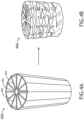
FIGS. 4A and 4B illustrates an energy absorber before and after plastic deformation, respectively, according to an embodiment of the present disclosure; and -
FIG. 5 illustrates an energy absorber according to the present disclosure utilized in an aircraft seating application. - Before explaining at least one embodiment of the inventive concepts disclosed herein in detail, it is to be understood that the inventive concepts are not limited in their application to the details of construction and the arrangement of the components or steps or methodologies set forth in the following description or illustrated in the drawings. In the following detailed description of embodiments of the instant inventive concepts, numerous specific details are set forth in order to provide a more thorough understanding of the inventive concepts. However, it will be apparent to one of ordinary skill in the art having the benefit of the instant disclosure that the inventive concepts disclosed herein may be practiced without these specific details. In other instances, well-known features may not be described in detail to avoid unnecessarily complicating the instant disclosure. The inventive concepts disclosed herein are capable of other embodiments or of being practiced or carried out in various ways. Also, it is to be understood that the phraseology and terminology employed herein is for the purpose of description and should not be regarded as limiting.
- As used herein, a letter following a reference numeral is intended to reference an embodiment of the feature or element that may be similar, but not necessarily identical, to a previously described element or feature bearing the same reference numeral (e.g., 1, 1a, 1b). Such shorthand notations are used for purposes of convenience only, and should not be construed to limit the inventive concepts disclosed herein in any way unless expressly stated to the contrary.
- Further, unless expressly stated to the contrary, "or" refers to an inclusive or and not to an exclusive or. For example, a condition A or B is satisfied by anyone of the following: A is true (or present) and B is false (or not present), A is false (or not present) and B is true (or present), and both A and B are true (or present).
- In addition, use of the "a" or "an" are employed to describe elements and components of embodiments of the instant inventive concepts. This is done merely for convenience and to give a general sense of the inventive concepts, and "a" and "an" are intended to include one or at least one and the singular also includes the plural unless it is obvious that it is meant otherwise.
- Finally, as used herein any reference to "one embodiment" or "some embodiments" means that a particular element, feature, structure, or characteristic described in connection with the embodiment is included in at least one embodiment of the inventive concepts disclosed herein. The appearances of the phrase "in some embodiments" in various places in the specification are not necessarily all referring to the same embodiment, and embodiments of the inventive concepts disclosed may include one or more of the features expressly described or inherently present herein, or any combination of sub-combination of two or more such features, along with any other features which may not necessarily be expressly described or inherently present in the instant disclosure.
- Broadly, the present disclosure is directed to methods for manufacturing energy absorbers including additive manufacturing and heat treatment processes, heat treatments for improving performance of energy absorbers, and aircraft seating applications including energy absorbers. In embodiments, energy absorbers according to the present disclosure operate based on performance of a collapsible structure with varying stiffness, and can be used, for example, in helicopter seating systems. The collapsible structure of the energy absorber is configured to absorb input kinetic energy by successive buckling or crushing due to axial compression. In embodiments, a varying stiffness introduced along the length of the energy absorber achieves variable energy absorption for various occupants ranging from the 5th to the 95th percentile occupant size.
- Some advantages of the disclosed energy absorbers include, but are not limited to, predictable elastic deformation behavior, maximum energy absorption per unit stroke distance, customizable threshold crushing force, reduction of deformations in the finished product, reduced heat treatment cycle, and reduced manufacturing costs.
-
FIG. 1 illustrates an example implementation of amethod 100 for manufacturing an energy absorber as described herein. In general, certain operations of disclosed processes (e.g., method 100) may be performed in an arbitrary order, unless otherwise provided in the claims. - At
step 102, themethod 100 includes providing an additive manufacturing system including a build plate. Additive manufacturing systems suitable for building an energy absorber according to the present disclosure include, but are not limited to, selective laser melting (SLM), electron beam melting (EBM), laser powder bed fusion (LPBF), and other well-known additive manufacturing processes. Atstep 104, themethod 100 includes building the energy absorber on (e.g., atop) the build plate layer-by-layer until completion. - At
step 106, themethod 100 includes heating the build plate including the built energy absorber (i.e., without separating the built energy absorber from the build plate) in a heating furnace to a solutionizing temperature in a range of 300°C to 550°C, preferably 350°C to 500°C, more preferably 400°C to 450°C, and most preferably substantially 430°C (e.g., 430°C ±5°C). Atstep 108, themethod 100 includes maintaining the solutionizing temperature for a time of 4 to 6 hours, more preferably substantially 5 hours. In embodiments, for the defined solutionizing temperature ranges, a holding time of substantially 5 hours was determined to be optimal. In astep 110, themethod 100 includes water quenching the heated build plate including the attached built energy absorber (i.e., still without separating the built energy absorber from the build plate). - The present inventors found that such a solutionizing temperature range, holding time, and water quench cooling as mentioned above, for a built energy absorber of the composition AlSi10mG, resulted in maximum energy absorption performance per unit stroke distance. At
step 112, themethod 100 includes separating the heat treated built energy absorber from the build plate. Atstep 114, themethod 100 concludes with optionally finish processing the heat treated energy absorber, for instance with a glass bead powder polish. Themethod 100 may further include any step or operation implied or required by the embodiments of the current energy absorbers described herein. -
FIG. 2 illustrates an example implementation of amethod 200 for thermally treating an already additively manufactured energy absorber. In general, certain operations of disclosed processes (e.g., method 200) may be performed in an arbitrary order, unless otherwise provided in the claims. Atstep 202, the method includes providing a build plate including an already built, by an additive manufacturing process, energy absorber positioned atop the build plate (i.e., attached to the built plate post build). - At
step 204, themethod 200 includes heating the build plate including the built energy absorber (i.e., without separating the built energy absorber from the build plate) in a heating furnace to a solutionizing temperature in a range of 300°C to 550°C, preferably 350°C to 500°C, more preferably 400°C to 450°C, and most preferably substantially 430°C (e.g., 430°C ±5°C). Atstep 206, themethod 200 includes maintaining the solutionizing temperature for a time of 4 to 6 hours, more preferably substantially 5 hours. In embodiments, for the defined solutionizing temperature ranges, a holding time of substantially 5 hours was determined to be optimal. In astep 208, themethod 200 includes water quenching the heated build plate including the attached built energy absorber (i.e., still without separating the built energy absorber from the build plate). Atstep 210, themethod 200 includes separating the heat treated built energy absorber from the build plate. Atstep 212, themethod 200 concludes with optionally finish processing the heat treated energy absorber, for instance with a glass bead powder polish. Themethod 200 may further include any step or operation implied or required by the embodiments of the current energy absorbers described herein. -
FIGS. 3A-C illustrate exemplary heat treatment cycles according to themethods - It is to be understood that embodiments of the methods according to the inventive concepts disclosed herein may include one or more of the steps described herein. Further, such steps may be carried out in any desired order and two or more of the steps may be carried out simultaneously with one another. Two or more of the steps disclosed herein may be combined in a single step, and in some embodiments, one or more of the steps may be carried out as two or more sub-steps. Further, other steps or sub-steps may be carried in addition to, or as substitutes to, one or more of the steps disclosed herein.
-
FIG. 4A and 4B illustrate a particular embodiment of an additively manufactured energy absorber of the composition AISi10Mg. In embodiments, the composition of AlSi10Mg may include about 90% aluminum, about 9% silicon, and about 1% magnesium. In embodiments, the aluminum alloy may contain amounts of other elements such as iron, copper, and zinc, in comparatively small amounts, for improved mechanical properties and resistance to corrosion. The exact composition of AlSil OMg may vary depending on the specific manufacturing process used and the intended application of the alloy. Such an aluminum alloy is optimal for use in aircraft applications due to its high strength-to-weight ratio and resistance to corrosion, as well as optimal for use in additive manufacturing processes to produce highly precise and complex geometries. - As shown in
FIG. 4A , anenergy absorber 400 as manufactured and/or thermally treated according to above methods, may be utilized in an energy attenuation system provided in an aircraft, such as a helicopter seating application. In use, a seat may be configured to act in a predefined manner in response to a high g-force event (e.g., 13-14.5 times the acceleration of gravity). Theenergy absorber 400 is configured as a collapsible structure usable as a single use feature. In use, at the failure of a primary seat element (e.g., predefined threshold force value), theenergy absorber 400 may be in contact with a separate element movable along a motion path. Theenergy absorber 400 plastically deforms to slow the acceleration of the separate element. In embodiments, the energy absorber may be configured to collapse at successive longitudinal portions in response to correspondingly successive compressive forces applied by the separate element. - In embodiments, the
energy absorber 400 may include anelongated hub 402, an elongatedexterior skin 404 eccentrically positioned in surrounding relation to theelongated hub 402, and a plurality of radially-extendingelongated spokes 406 extending between thehub 402 and theskin 404. Each elongated spoke 406 may extend radially outward from an exterior surface of theelongated hub 402 to an interior surface of the elongatedexterior skin 404 and may be tapered along a length thereof. Theelongate hub 402, the elongatedexterior skin 404, and each of the plurality ofspokes 406 may be symmetrical about a central longitudinal axis of theelongated hub 402, and each elongated spoke 406 may be substantially uniformly distant from neighboringelongated spokes 406 about theelongated hub 402, and the elongatedexterior skin 404 may take the form of a circular element or a polygonal element. In the latter case, the polygonal element may be defined such that each vertex 408 is provided at a location at which the elongatedexterior skin 404 is connected to a distal edge of a corresponding one of theelongated spokes 406. - In embodiments, the energy absorber may be a thin-walled or multi-walled structure. In embodiments, a variable compressibility profile may be achieved by the shape of the
elongated spokes 406. For example, theelongated spokes 406 may have a first thickness proximal to one end of theenergy absorber 400, and a second thickness, different from the first thickness, proximal to the opposite end of theenergy absorber 400. In embodiments, each of theelongated spokes 406 may taper gradually from one end to the other end of theenergy absorber 400 such that energy absorption performance increases as the energy absorber continues to compress axially. -
FIG. 4B shows theenergy absorber 400 in a crushed condition (i.e., plastically deformed). In use, the energy absorber formed as a column is configured to crush by way of buckling and successive crushing for energy absorption. In other embodiments, the energy absorber may be in the form of a lattice structure and may or may not include one solid end. -
FIG. 5 illustrates theenergy absorber 400 implemented in a seating application wherein the energy absorber is coupled between aseat 502 movable relative to a supportingseat frame 504. In embodiments, theenergy absorber 400 may form a dynamic connection between a seat element and a frame element. In use, in the absence of force on theenergy absorber 400 and/or on the attached elements meeting a predetermined threshold force, theenergy absorber 400 may act as a rigid link interconnecting the elements. When a predetermined threshold force is exceeded, theenergy absorber 400 undergoes a plastic deformation (i.e., without recovery) in a predictable manner. To attenuate the force on the attached elements, theenergy absorber 400 deforms according to the acting force. For example, the threshold force may correspond to a compressive threshold that when met causes theenergy absorber 400 to compress. - While the disclosure is provided in detail in connection with only a limited number of embodiments, it should be readily understood that the disclosure is not limited to such disclosed embodiments. Rather, the disclosure can be modified to incorporate any number of variations falling within the scope of the invention as defined by the claims. Additionally, while various embodiments of the disclosure have been described, it is to be understood that the exemplary embodiment(s) may include only some of the described exemplary aspects.
Claims (11)
- A method of manufacturing an energy absorber, the method comprising the steps of:providing (102) a build plate;building, by an additive manufacturing process, an energy absorber atop the build plate;heating (106) the build plate including the built energy absorber in a heating furnace to a solutionizing temperature in a range of 300°C to 550°C;maintaining (108) the solutionizing temperature for 4 to 6 hours;water quenching (110) the heated build plate including the built energy absorber;removing (112) the built energy absorber from the build plate.
- A method of thermally treating an additively manufactured energy absorber, the method comprising the steps of:providing a build plate including a built, by an additive manufacturing process, energy absorber positioned atop the build plate;heating the build plate including the built energy absorber in a heating furnace to a solutionizing temperature in a range of 300°C to 550°C;maintaining the solutionizing temperature for 4 to 6 hours;water quenching the heated build plate including the built energy absorber;removing the built energy absorber from the build plate; andoptionally finish processing the built energy absorber.
- The method according to claim 1 or 2, further comprising finish processing (114) the built energy absorber.
- The method according to claim 1, 2 or 3, wherein the solutionizing temperature is in the range of 350°C to 500°C, or wherein the solutionizing temperature is in the range of 400°C to 450°C, or wherein the solutionizing temperature is about 430°C.
- The method according to any preceding claim, wherein the energy absorber is a composition of AlSi10Mg.
- The method according to any preceding claim, wherein the additive manufacturing process is at least one of selective laser melting, SLM, and electron beam melting, EBM.
- The method according to any preceding claim, wherein a ramp-up rate to the solutionizing temperature is about 10°C per minute.
- The method according to claim 3 or any claim dependent thereon, wherein the finish processing comprises at least one polishing process.
- The method according to any preceding claim, wherein the built energy absorber is a collapsible structure comprising a hub, an exterior skin surrounding the hub, and a plurality of spokes extending outwardly from the hub to the exterior skin, wherein each spoke is tapered along a length thereof.
- The method according to claim 9, wherein:the hub, the exterior skin, and the plurality of spokes are symmetric about a central longitudinal axis of the hub;each spoke is uniformly distant from neighboring spokes about the hub; andthe exterior skin is polygonal with each vertex being connected to a spoke.
- The method according to claim 2 or any claim dependent thereon, wherein a height of the built energy absorber is no more than about 5 inches (12.7 cm), and an outer diameter of the built energy absorber is no more than about 2 inches (5.08 cm).
Applications Claiming Priority (2)
| Application Number | Priority Date | Filing Date | Title |
|---|---|---|---|
| IN202341069114 | 2023-10-13 | ||
| US18/519,499 US20250121437A1 (en) | 2023-10-13 | 2023-11-27 | Method of manufacturing an additively manufactured energy absorber to improve performance |
Publications (1)
| Publication Number | Publication Date |
|---|---|
| EP4537957A1 true EP4537957A1 (en) | 2025-04-16 |
Family
ID=93119412
Family Applications (1)
| Application Number | Title | Priority Date | Filing Date |
|---|---|---|---|
| EP24206503.5A Pending EP4537957A1 (en) | 2023-10-13 | 2024-10-14 | Method of manufacturing an additively manufactured energy absorber to improve performance |
Country Status (1)
| Country | Link |
|---|---|
| EP (1) | EP4537957A1 (en) |
Citations (6)
| Publication number | Priority date | Publication date | Assignee | Title |
|---|---|---|---|---|
| WO2013024883A1 (en) * | 2011-08-17 | 2013-02-21 | 昭和電工株式会社 | Shock absorbing member |
| US20190359096A1 (en) * | 2018-05-22 | 2019-11-28 | Ami Industries, Inc. | Collapsible structure with varying stiffness-based energy attenuation system |
| EP3922559A1 (en) * | 2020-06-13 | 2021-12-15 | B/E Aerospace, Inc. | Integrated seat pan cushion structure |
| US20210387734A1 (en) * | 2020-06-13 | 2021-12-16 | B/E Aerospace, Inc. | Integrated seat pan cushion structure |
| US20220177138A1 (en) * | 2019-03-29 | 2022-06-09 | Safran Seats Usa Llc | Additive manufactured aircraft seat components |
| FR3123235A1 (en) * | 2021-05-28 | 2022-12-02 | C-Tec Constellium Technology Center | Process for manufacturing an aluminum alloy part using an additive manufacturing technique with preheating. |
-
2024
- 2024-10-14 EP EP24206503.5A patent/EP4537957A1/en active Pending
Patent Citations (6)
| Publication number | Priority date | Publication date | Assignee | Title |
|---|---|---|---|---|
| WO2013024883A1 (en) * | 2011-08-17 | 2013-02-21 | 昭和電工株式会社 | Shock absorbing member |
| US20190359096A1 (en) * | 2018-05-22 | 2019-11-28 | Ami Industries, Inc. | Collapsible structure with varying stiffness-based energy attenuation system |
| US20220177138A1 (en) * | 2019-03-29 | 2022-06-09 | Safran Seats Usa Llc | Additive manufactured aircraft seat components |
| EP3922559A1 (en) * | 2020-06-13 | 2021-12-15 | B/E Aerospace, Inc. | Integrated seat pan cushion structure |
| US20210387734A1 (en) * | 2020-06-13 | 2021-12-16 | B/E Aerospace, Inc. | Integrated seat pan cushion structure |
| FR3123235A1 (en) * | 2021-05-28 | 2022-12-02 | C-Tec Constellium Technology Center | Process for manufacturing an aluminum alloy part using an additive manufacturing technique with preheating. |
Non-Patent Citations (1)
| Title |
|---|
| "Light Metal Alloys Applications", 11 June 2014, INTECH, ISBN: 978-953-51-1588-5, article DIEGO MANFREDI ET AL: "Additive Manufacturing of Al Alloys and Aluminium Matrix Composites (AMCs)", XP055410804, DOI: 10.5772/58534 * |
Similar Documents
| Publication | Publication Date | Title |
|---|---|---|
| EP2868759B1 (en) | ALPHA + BETA TYPE Ti ALLOY AND PROCESS FOR PRODUCING SAME | |
| KR102039770B1 (en) | Split-pass open-die forging for hard-to-forge, strain-path sensitive titanium-base and nickel-base alloys | |
| KR20150129644A (en) | Thermomechanical processing of alpha-beta titanium alloys | |
| JP6734890B2 (en) | Method for treating titanium alloy | |
| JP2016503126A5 (en) | ||
| NO168880B (en) | ENERGY-ABSORBING CONSTRUCTION FOR RECORDING OF ESTIMATED ENERGY AND PROCEDURE FOR THE PREPARATION OF THIS | |
| IL223713A (en) | Processing of alpha+beta titanium alloys | |
| US20100218860A1 (en) | Method for producing a molded sheet metal part from an as-rolled, non-hardenable aluminum alloy | |
| JPH03140447A (en) | Forging of microcrystalline titanium powder and method of its manufacture | |
| JPWO2004085685A1 (en) | Manufacturing method of high strength spring | |
| AU715907B2 (en) | Method of manufacturing helical springs | |
| EP2444200B1 (en) | Method for manufacturing coil spring | |
| WO2012039927A1 (en) | High strength alpha/beta titanium alloy fasteners and fastener stock | |
| US20250121437A1 (en) | Method of manufacturing an additively manufactured energy absorber to improve performance | |
| KR20170051472A (en) | Method for producing cold-formed steel springs | |
| EP3406750B1 (en) | Single-piece extended laminar flow inlet lipskin | |
| Su et al. | Mechanical behaviour and texture of annealed AZ31 Mg alloy deformed by ECAP | |
| CN112080669B (en) | NiTi shape memory alloy with energy absorption and vibration reduction functions and preparation method and application thereof | |
| US20040189049A1 (en) | Crush zone and method for introducing crush zone into vehicle structure | |
| EP3347614B1 (en) | Tube spring for motor vehicles and method for producing a tube spring | |
| EP2003224B1 (en) | Secondary processing of structures derived from AI-RE-TM Alloys | |
| Griebel et al. | Cold-drawn ZM21 and WE43 wires exhibit exceptional strength and ductility | |
| Mohammadi et al. | Enhanced formability of age-hardenable aluminium alloys by incremental forming of solution-treated blanks | |
| EP4144873B1 (en) | Spinning process of magnesium alloy wheel hub | |
| Khalifa¹ et al. | Review on Shape Memory Alloys, Processing and Applications |
Legal Events
| Date | Code | Title | Description |
|---|---|---|---|
| PUAI | Public reference made under article 153(3) epc to a published international application that has entered the european phase |
Free format text: ORIGINAL CODE: 0009012 |
|
| STAA | Information on the status of an ep patent application or granted ep patent |
Free format text: STATUS: THE APPLICATION HAS BEEN PUBLISHED |
|
| AK | Designated contracting states |
Kind code of ref document: A1 Designated state(s): AL AT BE BG CH CY CZ DE DK EE ES FI FR GB GR HR HU IE IS IT LI LT LU LV MC ME MK MT NL NO PL PT RO RS SE SI SK SM TR |
|
| STAA | Information on the status of an ep patent application or granted ep patent |
Free format text: STATUS: REQUEST FOR EXAMINATION WAS MADE |
|
| 17P | Request for examination filed |
Effective date: 20251015 |