EP4537801A1 - Electric auxiliary driving apparatus and hospital bed with same - Google Patents
Electric auxiliary driving apparatus and hospital bed with same Download PDFInfo
- Publication number
- EP4537801A1 EP4537801A1 EP23825906.3A EP23825906A EP4537801A1 EP 4537801 A1 EP4537801 A1 EP 4537801A1 EP 23825906 A EP23825906 A EP 23825906A EP 4537801 A1 EP4537801 A1 EP 4537801A1
- Authority
- EP
- European Patent Office
- Prior art keywords
- support rod
- spring support
- driving device
- rocker
- electric auxiliary
- Prior art date
- Legal status (The legal status is an assumption and is not a legal conclusion. Google has not performed a legal analysis and makes no representation as to the accuracy of the status listed.)
- Pending
Links
Images


Classifications
-
- A—HUMAN NECESSITIES
- A61—MEDICAL OR VETERINARY SCIENCE; HYGIENE
- A61G—TRANSPORT, PERSONAL CONVEYANCES, OR ACCOMMODATION SPECIALLY ADAPTED FOR PATIENTS OR DISABLED PERSONS; OPERATING TABLES OR CHAIRS; CHAIRS FOR DENTISTRY; FUNERAL DEVICES
- A61G7/00—Beds specially adapted for nursing; Devices for lifting patients or disabled persons
- A61G7/05—Parts, details or accessories of beds
-
- A—HUMAN NECESSITIES
- A61—MEDICAL OR VETERINARY SCIENCE; HYGIENE
- A61G—TRANSPORT, PERSONAL CONVEYANCES, OR ACCOMMODATION SPECIALLY ADAPTED FOR PATIENTS OR DISABLED PERSONS; OPERATING TABLES OR CHAIRS; CHAIRS FOR DENTISTRY; FUNERAL DEVICES
- A61G7/00—Beds specially adapted for nursing; Devices for lifting patients or disabled persons
- A61G7/08—Apparatus for transporting beds
-
- B—PERFORMING OPERATIONS; TRANSPORTING
- B60—VEHICLES IN GENERAL
- B60B—VEHICLE WHEELS; CASTORS; AXLES FOR WHEELS OR CASTORS; INCREASING WHEEL ADHESION
- B60B33/00—Castors in general ; Anti-clogging castors
- B60B33/04—Castors in general ; Anti-clogging castors adjustable, e.g. in height; linearly shifting castors
- B60B33/06—Castors in general ; Anti-clogging castors adjustable, e.g. in height; linearly shifting castors mounted retractably
- B60B33/066—Castors in general ; Anti-clogging castors adjustable, e.g. in height; linearly shifting castors mounted retractably by use of a hinge and lever mechanism to swing wheel upwards relative to wheel mount
-
- A—HUMAN NECESSITIES
- A61—MEDICAL OR VETERINARY SCIENCE; HYGIENE
- A61G—TRANSPORT, PERSONAL CONVEYANCES, OR ACCOMMODATION SPECIALLY ADAPTED FOR PATIENTS OR DISABLED PERSONS; OPERATING TABLES OR CHAIRS; CHAIRS FOR DENTISTRY; FUNERAL DEVICES
- A61G7/00—Beds specially adapted for nursing; Devices for lifting patients or disabled persons
- A61G7/002—Beds specially adapted for nursing; Devices for lifting patients or disabled persons having adjustable mattress frame
- A61G7/018—Control or drive mechanisms
-
- A—HUMAN NECESSITIES
- A61—MEDICAL OR VETERINARY SCIENCE; HYGIENE
- A61G—TRANSPORT, PERSONAL CONVEYANCES, OR ACCOMMODATION SPECIALLY ADAPTED FOR PATIENTS OR DISABLED PERSONS; OPERATING TABLES OR CHAIRS; CHAIRS FOR DENTISTRY; FUNERAL DEVICES
- A61G7/00—Beds specially adapted for nursing; Devices for lifting patients or disabled persons
- A61G7/05—Parts, details or accessories of beds
- A61G7/0528—Steering or braking devices for castor wheels
-
- B—PERFORMING OPERATIONS; TRANSPORTING
- B60—VEHICLES IN GENERAL
- B60B—VEHICLE WHEELS; CASTORS; AXLES FOR WHEELS OR CASTORS; INCREASING WHEEL ADHESION
- B60B33/00—Castors in general ; Anti-clogging castors
- B60B33/0002—Castors in general ; Anti-clogging castors assembling to the object, e.g. furniture
- B60B33/0015—Castors in general ; Anti-clogging castors assembling to the object, e.g. furniture characterised by adaptations made to castor
- B60B33/0018—Castors in general ; Anti-clogging castors assembling to the object, e.g. furniture characterised by adaptations made to castor in the form of a flat mounting plate
-
- B—PERFORMING OPERATIONS; TRANSPORTING
- B60—VEHICLES IN GENERAL
- B60B—VEHICLE WHEELS; CASTORS; AXLES FOR WHEELS OR CASTORS; INCREASING WHEEL ADHESION
- B60B33/00—Castors in general ; Anti-clogging castors
- B60B33/04—Castors in general ; Anti-clogging castors adjustable, e.g. in height; linearly shifting castors
- B60B33/045—Castors in general ; Anti-clogging castors adjustable, e.g. in height; linearly shifting castors mounted resiliently, by means of dampers
-
- A—HUMAN NECESSITIES
- A61—MEDICAL OR VETERINARY SCIENCE; HYGIENE
- A61G—TRANSPORT, PERSONAL CONVEYANCES, OR ACCOMMODATION SPECIALLY ADAPTED FOR PATIENTS OR DISABLED PERSONS; OPERATING TABLES OR CHAIRS; CHAIRS FOR DENTISTRY; FUNERAL DEVICES
- A61G2203/00—General characteristics of devices
- A61G2203/70—General characteristics of devices with special adaptations, e.g. for safety or comfort
-
- A—HUMAN NECESSITIES
- A61—MEDICAL OR VETERINARY SCIENCE; HYGIENE
- A61G—TRANSPORT, PERSONAL CONVEYANCES, OR ACCOMMODATION SPECIALLY ADAPTED FOR PATIENTS OR DISABLED PERSONS; OPERATING TABLES OR CHAIRS; CHAIRS FOR DENTISTRY; FUNERAL DEVICES
- A61G5/00—Chairs or personal conveyances specially adapted for patients or disabled persons, e.g. wheelchairs
- A61G5/04—Chairs or personal conveyances specially adapted for patients or disabled persons, e.g. wheelchairs motor-driven
- A61G5/047—Chairs or personal conveyances specially adapted for patients or disabled persons, e.g. wheelchairs motor-driven by a modular detachable drive system
-
- B—PERFORMING OPERATIONS; TRANSPORTING
- B60—VEHICLES IN GENERAL
- B60B—VEHICLE WHEELS; CASTORS; AXLES FOR WHEELS OR CASTORS; INCREASING WHEEL ADHESION
- B60B2200/00—Type of product being used or applied
- B60B2200/20—Furniture or medical appliances
- B60B2200/24—Beds
- B60B2200/242—Hospital beds
-
- B—PERFORMING OPERATIONS; TRANSPORTING
- B60—VEHICLES IN GENERAL
- B60B—VEHICLE WHEELS; CASTORS; AXLES FOR WHEELS OR CASTORS; INCREASING WHEEL ADHESION
- B60B2900/00—Purpose of invention
- B60B2900/10—Reduction of
- B60B2900/114—Size
Definitions
- the invention relates to the technical field of smart homes, and particularly relates to an electric auxiliary driving device and a hospital bed with the electric auxiliary driving device.
- the movable bed is further provided with an auxiliary driver to relieve pressure of workers.
- the auxiliary driver includes rollers and an electric motor connected with the rollers in a driving manner.
- the rollers can be driven to rotate by the electric motor, and springs are arranged between the bed and the rollers, such that the rollers always cling to a bottom surface.
- the auxiliary driver in the related art is arranged vertically, and occupies large space in a height direction.
- the invention provides an electric auxiliary driving device and a hospital bed with the electric auxiliary driving device, so as to solve a problem that an auxiliary driver in the related art occupies large space.
- the electric auxiliary driving device includes: a mounting support fixedly connected with a furniture; a rocker, wherein a first end of the rocker is provided with a rotatable roller, and a second end of the rocker is hinged to the mounting support; a pulling device connected with the rocker, wherein the pulling device is connected with the roller in a driving manner; a lifting device including a driving device and a sliding block moving along a straight line, wherein the driving device drives the rocker to rotate by driving the sliding block to move; and a balancing device including a spring support rod, wherein a first end of the spring support rod is hinged to the rocker, and a second end of the spring support rod is hinged to the sliding block.
- the balancing device further includes a guiding structure.
- the guiding structure extends along the straight line.
- the guiding structure includes a guiding element and a guiding groove.
- the guiding element is inserted into the guiding groove.
- the guiding groove is provided on one of the mounting support or the sliding block.
- the guiding element is arranged on the other one of the mounting support or the sliding block.
- the guiding element includes a linear guide rail arranged on a side wall of the sliding block.
- the mounting support is provided with two parallel guiding plates. A space between the two guiding plates forms the guiding groove.
- the guiding element includes a linear guide rail arranged on a bottom wall of the sliding block.
- the mounting support is provided with two parallel guiding ribs. A space between the two guiding ribs forms the guiding groove.
- the driving device includes a first gear motor and a first spindle.
- the first gear motor drives the first spindle to rotate.
- the first spindle is provided with an external thread.
- the sliding block is provided with a first threaded hole.
- the external thread is connected with the first threaded hole in a threaded manner.
- the driving device includes a driving motor and a second spindle connected with the driving motor in a driving manner.
- the second spindle is connected with the sliding block and drives the sliding block to move along the straight line.
- the lifting device further includes a worm wheel and a worm that are capable of rotating relatively and cooperating with each other.
- the driving motor includes a second gear motor. An output end of the second gear motor is connected with the worm in a driving manner. Teeth of the worm are engaged with external teeth of the worm wheel.
- the worm wheel is provided with a second threaded hole. The second spindle penetrates the second threaded hole and is connected with the worm wheel in a threaded manner.
- the lifting device further includes a worm wheel housing fixedly connected with the mounting support.
- the worm wheel is arranged in the worm wheel housing.
- the lifting device further includes a first rolling bearing and a second rolling bearing.
- the worm wheel housing includes a first worm wheel half-housing and a second worm wheel half-housing connected to each other. An inner ring of the first rolling bearing and an inner ring of the second rolling bearing are sleeved on two ends of the worm wheel respectively.
- the first worm wheel half-housing and the second worm wheel half-housing are configured to fasten outer rings of the first rolling bearing and the second rolling bearing.
- the spring support rod includes a spring support rod shaft, an upper spring support rod head and a lower spring support rod head.
- An upper end of the spring support rod shaft is inserted into a first end of the upper spring support rod head.
- a second end of the upper spring support rod head is hinged to the sliding block.
- a first end of the lower spring support rod head is hinged to the rocker.
- a second end of the lower spring support rod head is connected with a lower end of the spring support rod shaft.
- the balancing device further includes a first compression spring being sleeved on a periphery of the spring support rod shaft. The first compression spring is sandwiched between the upper spring support rod head and the lower spring support rod head.
- the balancing device further includes an upper spring support rod bearing, a lower spring support rod bearing, a first articulated shaft and a second articulated shaft.
- the second end of the upper spring support rod head is hinged to the sliding block through the first articulated shaft.
- An inner ring of the upper spring support rod bearing is sleeved on a periphery of the first articulated shaft.
- An outer ring of the upper spring support rod bearing is sleeved on the second end of the upper spring support rod head.
- the first end of the lower spring support rod head is hinged to the rocker through the second articulated shaft.
- An inner ring of the lower spring support rod bearing is sleeved on a periphery of the second articulated shaft.
- An outer ring of the lower spring support rod bearing is sleeved on the first end of the lower spring support rod head.
- the spring support rod shaft includes a tap bolt.
- the upper spring support rod head is provided with a first stepped hole in a penetrating manner.
- a bolt head of the tap bolt is movably inserted into the first stepped hole.
- a bolt shank of the tap bolt is connected with the lower spring support rod head.
- the tap bolt includes a reaming bolt.
- a threaded shank of the reaming bolt is connected with the lower spring support rod head.
- the spring support includes an inserting seat and an inserting pin.
- a first end of the inserting seat is hinged to the rocker.
- a first end of the inserting pin is inserted into a second end of the inserting seat.
- a second end of the inserting pin is hinged to the sliding block.
- the balancing device further includes a second compression spring sleeved on a periphery of the spring support rod. The second compression spring is sandwiched between the inserting seat and the inserting pin.
- the rocker includes a connecting section and a bearing fork connected to each other.
- the bearing fork includes two bearing fork arms arranged at two sides of the roller respectively.
- the pulling device is connected with one of the bearing fork arms.
- the roller is provided with a roller shaft. One end of the roller shaft is rotatably connected with the bearing fork. An output end of the pulling device is connected with the other end of the roller shaft in a driving manner.
- an upper surface of the mounting support 10 is fixedly connected with a lower surface of the furniture, the rocker 20 is located in a rear zone below the mounting support 10, the pulling device 50 is located at one side of the rocker 20 and connected with the side of the rocker 20, and the lifting device 30 is located in a front zone below the mounting support 10.
- the roller can be completely located in the rear zone below the mounting support 10.
- a minimum height of the electric auxiliary driving device in the invention is completely determined by a diameter of the roller 21 after the roller 21 is retracted.
- an avoidance groove in a central zone of the mounting support 10 can also be designed so as to accommodate the roller, such that the minimum height of the electric auxiliary driving device corresponds to the diameter of the roller 21.
- the rocker 20 can firstly rotate downward around a hinge point to the mounting support 10, such that the rocker can enter its driving position so as to enable the roller 21 to be in contact with the ground. Then, the balancing device 40 may compensate for an uneven part, for instance, a protrusion and a recess, of the ground at the position, such that the roller 21 is always kept in contact with the ground.
- the guiding element includes a linear guide rail 44.1 arranged on a side wall of the sliding block 44, a side wall of the mounting support 10 is provided with two parallel guiding plates, and a space between the two guiding plates forms the guiding groove 12.
- the guiding element and the guiding groove 12 of the above structure have advantages of simple structure and convenient processing.
- the guiding element includes a linear guide rail 44.1 arranged on a bottom wall of the sliding block 44, a bottom wall of the mounting support 10 is provided with two parallel guiding ribs, and a space between the two guiding ribs forms the guiding groove 12.
- the driving device includes a driving motor 31 and a second spindle 35 connected with the driving motor 31 in a driving manner.
- the second spindle 35 is connected with the sliding block 44 and drives the sliding block 44 to move along the straight line.
- the driving motor 31 can drive the second spindle 35, and the second spindle 35 can drive the sliding block 44 to move along the straight line, such that advantages of simple driving structure and simple transmission structure are achieved.
- a second end of the sliding block 44 is provided with a lining 44.2.
- the lining 44.2 is provided with a fixing hole 44.3.
- a first end of the second spindle 35 is inserted into the lining 44.2.
- the second spindle 35 and the sliding block 44 are connected by inserting a fixing pin into the fixing hole.
- the driving device includes a first gear motor and a first spindle.
- the first gear motor drives the first spindle to rotate.
- the first spindle is provided with an external thread.
- the sliding block 44 is provided with a first threaded hole.
- the external thread is connected with the first threaded hole in a threaded manner.
- the lifting device 30 further includes a worm wheel 33 and a worm 32 that are capable of rotating relatively and cooperating with each other.
- the driving motor 31 includes a second gear motor. An output end of the second gear motor is connected with the worm 32 in a driving manner. Teeth of the worm 32 are engaged with external teeth 33.2 of the worm wheel 33.
- the worm wheel 33 is provided with a second threaded hole 33.1.
- the second spindle 35 penetrates the second threaded hole 33.1 and is connected with the worm wheel 33 in a threaded manner.
- a shifting cam ring 37 is sleeved on a second end of the second spindle 35. Extension or retraction of the second spindle 35 is implemented through alternate cooperation of the shifting cam ring 37 with a first limiting switch 38 or a second limiting switch 39.
- the lifting device 30 further includes a first rolling bearing 33.3 and a second rolling bearing 33.4.
- the worm wheel housing 34 includes a first worm wheel half-housing 34.1 and a second worm wheel half-housing 34.2 connected to each other. An inner ring of the first rolling bearing 33.3 and an inner ring of the second rolling bearing 33.4 are sleeved on two ends of the worm wheel 33 respectively.
- the first worm wheel half-housing 34.1 and the second worm wheel half-housing 34.2 are configured to fasten outer rings of the first rolling bearing 33.3 and the second rolling bearing 33.4. With the first rolling bearing 33.3 and the second rolling bearing 33.4, the worm wheel 33 can be centered, and a rotation process of the worm wheel 33 is smoother.
- a bottom wall of the mounting support 10 is further connected with a housing 14.
- the driving motor 31, the worm wheel 33 and the worm 32 are all located in a space defined by the mounting support 10 and the housing 14.
- the second spindle 35 is also located in the space defined by the mounting support 10 and the housing 14.
- the housing 14 can be configured to protect the above components.
- the spring support rod 43 includes a spring support rod shaft 43.3, an upper spring support rod head 43.1 and a lower spring support rod head 43.2.
- An upper end of the spring support rod shaft 43.3 is inserted into a first end of the upper spring support rod head 43.1.
- a second end of the upper spring support rod head 43.1 is hinged to the sliding block 44.
- a first end of the lower spring support rod head 43.2 is hinged to the rocker 20.
- a second end of the lower spring support rod head 43.2 is connected with a lower end of the spring support rod shaft 43.3.
- the balancing device 40 further includes a first compression spring 43.4 sleeved on a periphery of the spring support rod shaft 43.3.
- the first compression spring 43.4 is sandwiched between the upper spring support rod head 43.1 and the lower spring support rod head 43.2.
- the first compression spring 43.4 can achieve a buffering effect, such that the spring support rod 43 can move quickly in the upper spring support rod head 43.1 and the lower spring support rod head 43.2 under an elastic force of the spring when the roller 21 meets the recess or the protrusion on the ground.
- the rocker 20 rotates quickly for a response, such that the roller 21 can always abut against the ground.
- the balancing device 40 further includes an upper spring support rod bearing 41, a lower spring support rod bearing 42, a first articulated shaft and a second articulated shaft.
- the second end of the upper spring support rod head 43.1 is hinged to the sliding block 44 through the first articulated shaft.
- An inner ring of the upper spring support rod bearing 41 is sleeved on a periphery of the first articulated shaft.
- An outer ring of the upper spring support rod bearing 41 is sleeved on the second end of the upper spring support rod head 43.1.
- the first end of the lower spring support rod head 43.2 is hinged to the rocker 20 through the second articulated shaft.
- An inner ring of the lower spring support rod bearing 42 is sleeved on a periphery of the second articulated shaft.
- An outer ring of the lower spring support rod bearing 42 is sleeved on the first end of the lower spring support rod head 43.2.
- the spring support rod shaft 43.3 includes a tap bolt.
- the upper spring support rod head 43.1 is provided with a first stepped hole in a penetrating manner.
- a bolt head of the tap bolt is movably inserted into the first stepped hole.
- a bolt shank of the tap bolt is connected with the lower spring support rod head 43.2.
- the tap bolt includes a reaming bolt.
- a threaded shank of the reaming bolt is connected with the lower spring support rod head 43.2.
- a lower end of the reaming bolt can form a fixed end, and an upper end of the reaming bolt can form a moving end, such that the reaming bolt can conveniently move in the upper spring support rod head 43.1, so as to guide the rocker 20.
- the roller 21 when the roller 21 is at the retraction position, the second spindle 35 is at a front end of the mounting support 10, and the sliding block 44 drives the upper spring support rod head 43.1 to be located close to the worm wheel 33.
- the upper spring support rod head 43.1 has the maximum distance from the lower spring support rod head 43.2, the spring support rod shaft 43.3 abuts against the stepped surface of the first stepped hole, and the spring support rod 43 drives the first end of the rocker 20 to be located close to the mounting support 10. In this way, a containment effect on the rocker 20 is achieved, and the roller 21 can be retracted.
- the driving motor 31 drives the worm 32 to rotate, such that the worm 32 drives the worm wheel 33 to rotate, then the second spindle 35 is driven to move to a rear end of the mounting support 10, and the second spindle 35 drives the sliding block 44 to move in an extension direction of the guiding structure.
- the sliding block 44 drives the upper spring support rod head 43.1 to move along the straight line, and the spring support rod 43 drives the rocker 20 to rotate under the elastic force of the first compression spring 43.4.
- the roller 21 abuts against the ground, and meanwhile, the pulling device drives the roller 21 to rotate, such that the electric auxiliary driving device can drive the furniture to move.
- the first compression spring 43.4 is in a compressed state.
- the maximum height of the recess or the protrusion on the ground that can be compensated by the roller 21 is 20 mm.
- an actual compensation value can be changed according to parameters such as a distance between limiting switches, an extension length of the spring support rod 43 or a mounting position of the auxiliary driving device.
- the second spindle 35 is always in a state of extending out of the rear end of the mounting support 10.
- an additional vertical shaft can be designed to enable the roller 21 to turn.
- the auxiliary driving device can also be provided with one or more rollers.
- two parallel and spaced rollers 21 are designed, and each roller 21 is provided with a separate motor.
- two auxiliary drivers are arranged as a pair in a spaced manner. Turning can also be implemented by controlling an electric motor located outside a curve to rotate faster than the other electric motor.
- driving motors 31 all types can be regarded as driving motors 31.
- a gear motor provided with the worm wheel 33 is preferred.
- a gearless motor of a brushless direct current motor type can also be used.
- the rocker 20 includes a connecting section and a bearing fork 24 connected to each other.
- the bearing fork 24 includes two bearing fork arms arranged at two sides of the roller 21 respectively.
- the pulling device 50 is connected with one of the bearing fork arms.
- the roller 21 is provided with a roller shaft 22.
- One end of the roller shaft 22 is rotatably connected with the bearing fork 24.
- An output end of the pulling device 50 is connected with the other end of the roller shaft 22 in a driving manner.
- a second end of the connecting section is hinged to the mounting support 10.
- the electric auxiliary driving device further includes a rocker bearing shaft 11.
- the mounting support 10 is hinged to the second end of the rocker 20 through the rocker bearing shaft 11.
- the spring support rod 43 is movably arranged between the roller 21 and the rocker bearing shaft 11.
- the mounting support 10 can be hinged to the rocker 20 by the rocker bearing shaft 11, achieving an advantage of simple structure.
- the rocker 20 further includes a web plate 25.
- the two bearing fork arms are connected through one side of the web plate 25.
- the other side of the web plate 25 is connected with the connecting section.
- the connecting section and the bearing fork 24 are connected by the web plate 25, achieving an advantage of simple connection structure.
- the connecting section is provided with a groove 23 disposed obliquely downwards.
- the first end of the spring support rod 43 is inserted into the groove 23.
- the groove 23 can avoid the spring support rod 43, achieving an advantage of convenient arrangement.
- a first end of the spring support rod shaft 43.3 and the lower spring support rod head 43.2 are both located in the groove 23.
- the mounting support 10 is provided with a stopper.
- the stopper abuts against the bearing fork 24 so as to limit a rotation angle of the rocker 20. With the stopper, the rocker 20 can be limited when the rocker 20 is at the retraction position, thus protecting the roller 21.
- the pulling device 50 includes a third gear motor 51.
- the third gear motor 51 and a transmission device are transversely arranged on a left arm of the bearing fork 24.
- output of the third gear motor 51 is directly applied to the roller shaft 22.
- Embodiment 2 of the invention provides an electric auxiliary driving device.
- Embodiment 2 and Embodiment 1 are different in that, in Embodiment 2, as shown in Figs. 11-14 , the spring support rod 43 includes an inserting seat 45 and an inserting pin 46, a first end of the inserting seat 45 is hinged to the rocker 20, a first end of the inserting pin 46 is inserted into a second end of the inserting seat 45, and a second end of the inserting pin 46 is hinged to a sliding block 44.
- the inserting pin 46 can slide in the inserting seat 45, and the electric auxiliary driving device can adapt to a recess or a protrusion on the ground, such that the roller 21 can be always kept in contact with the ground, and a use scope of the electric auxiliary driving device can be enlarged.
- the balancing device 40 further includes a second compression spring sleeved on a periphery of the spring support rod 43, and the second compression spring is sandwiched between the inserting seat 45 and the inserting pin 46.
- the second compression spring can achieve a buffering effect, such that the spring support rod 43 can move quickly in the upper spring support rod head 43.1 and the lower spring support rod head 43.2 under an elastic force of the spring when the roller 21 meets the recess or the protrusion on the ground.
- the rocker 20 rotates quickly for a response, such that the roller 21 can always abut against the ground.
- the spring support rod 43 further includes a limiting member 47 connected with the first end of the inserting pin 46.
- the inserting pin 46 includes an inserting pin rod 46.1 and an inserting pin head 46.2 connected to each other.
- the first end of the inserting seat 45 is hinged to the rocker 20.
- the second end of the inserting seat 45 is provided with a second stepped hole.
- the inserting pin rod 46.1 is movably inserted into the second stepped hole.
- a second end of the inserting pin head 46.2 is hinged to the sliding block 44.
- the inserting pin head 46.2 When the inserting pin head 46.2 has a minimum distance from the inserting seat 45, the inserting pin head 46.2 abuts against the inserting seat 45.
- an upper end of the inserting pin rod 46.1 forms a fixed end, and a lower end of the inserting pin rod forms a moving end, such that the inserting pin rod 46.1 moves conveniently in the inserting seat 45, so as to guide the rocker 20.
- the inserting pin head 46.2 has the minimum distance from the inserting seat 45, and the inserting pin head 46.2 abuts against the inserting seat 45, such that a rotation angle of the rocker 20 is limited, and the roller 21 can compensate for the protrusion on the ground.
- the inserting pin head 46.2 has the maximum distance from the inserting seat 45, and the limiting member 47 abuts against the stepped surface of the second stepped hole, such that a rotation angle of the rocker 20 is limited, and the roller 21 can compensate for the recess on the ground.
- Embodiment 3 of the invention provides a hospital bed.
- the hospital bed includes a bed body and an electric auxiliary driving device.
- a mounting support of the electric auxiliary driving device is connected with the bed body.
- the electric auxiliary driving device includes the above-mentioned electric auxiliary driving device.
- the lifting device and the balancing device are connected by the sliding block 44 moving linearly, and the sliding block 44 moves linearly in a horizontal direction.
- a lifting function of the electric auxiliary driving device can be achieved in a very small mounting space.
- other parts of the electric auxiliary driving device are all arranged below the mounting support 10, reducing mounting space in a height direction.
Landscapes
- Health & Medical Sciences (AREA)
- Nursing (AREA)
- Life Sciences & Earth Sciences (AREA)
- Animal Behavior & Ethology (AREA)
- General Health & Medical Sciences (AREA)
- Public Health (AREA)
- Veterinary Medicine (AREA)
- Engineering & Computer Science (AREA)
- Mechanical Engineering (AREA)
- Invalid Beds And Related Equipment (AREA)
Abstract
Description
- The invention claims the priority to Patent Application No.
202210719281.0, filed to the China National Intellectual Property Administration on June 23, 2022 - The invention relates to the technical field of smart homes, and particularly relates to an electric auxiliary driving device and a hospital bed with the electric auxiliary driving device.
- The emergence of movable furniture, especially movable beds, has brought great convenience to people's daily life. Four rollers are generally arranged at four corners of the movable bed. In a moving process, friction between the bed and the ground is greatly reduced through rolling of the rollers, thereby achieving the purpose of saving labor.
- In the related art, the movable bed is further provided with an auxiliary driver to relieve pressure of workers. The auxiliary driver includes rollers and an electric motor connected with the rollers in a driving manner. The rollers can be driven to rotate by the electric motor, and springs are arranged between the bed and the rollers, such that the rollers always cling to a bottom surface. However, the auxiliary driver in the related art is arranged vertically, and occupies large space in a height direction.
- The invention provides an electric auxiliary driving device and a hospital bed with the electric auxiliary driving device, so as to solve a problem that an auxiliary driver in the related art occupies large space.
- One aspect of the invention provides an electric auxiliary driving device. The electric auxiliary driving device includes: a mounting support fixedly connected with a furniture; a rocker, wherein a first end of the rocker is provided with a rotatable roller, and a second end of the rocker is hinged to the mounting support; a pulling device connected with the rocker, wherein the pulling device is connected with the roller in a driving manner; a lifting device including a driving device and a sliding block moving along a straight line, wherein the driving device drives the rocker to rotate by driving the sliding block to move; and a balancing device including a spring support rod, wherein a first end of the spring support rod is hinged to the rocker, and a second end of the spring support rod is hinged to the sliding block.
- Further, the balancing device further includes a guiding structure. The guiding structure extends along the straight line. The guiding structure includes a guiding element and a guiding groove. The guiding element is inserted into the guiding groove. The guiding groove is provided on one of the mounting support or the sliding block. The guiding element is arranged on the other one of the mounting support or the sliding block.
- Further, the guiding element includes a linear guide rail arranged on a side wall of the sliding block. The mounting support is provided with two parallel guiding plates. A space between the two guiding plates forms the guiding groove. Alternatively, the guiding element includes a linear guide rail arranged on a bottom wall of the sliding block. The mounting support is provided with two parallel guiding ribs. A space between the two guiding ribs forms the guiding groove.
- Further, the driving device includes a first gear motor and a first spindle. The first gear motor drives the first spindle to rotate. The first spindle is provided with an external thread. The sliding block is provided with a first threaded hole. The external thread is connected with the first threaded hole in a threaded manner.
- Further, the driving device includes a driving motor and a second spindle connected with the driving motor in a driving manner. The second spindle is connected with the sliding block and drives the sliding block to move along the straight line.
- Further, the lifting device further includes a worm wheel and a worm that are capable of rotating relatively and cooperating with each other. The driving motor includes a second gear motor. An output end of the second gear motor is connected with the worm in a driving manner. Teeth of the worm are engaged with external teeth of the worm wheel. The worm wheel is provided with a second threaded hole. The second spindle penetrates the second threaded hole and is connected with the worm wheel in a threaded manner.
- Further, the lifting device further includes a worm wheel housing fixedly connected with the mounting support. The worm wheel is arranged in the worm wheel housing. The lifting device further includes a first rolling bearing and a second rolling bearing. The worm wheel housing includes a first worm wheel half-housing and a second worm wheel half-housing connected to each other. An inner ring of the first rolling bearing and an inner ring of the second rolling bearing are sleeved on two ends of the worm wheel respectively. The first worm wheel half-housing and the second worm wheel half-housing are configured to fasten outer rings of the first rolling bearing and the second rolling bearing.
- Further, the spring support rod includes a spring support rod shaft, an upper spring support rod head and a lower spring support rod head. An upper end of the spring support rod shaft is inserted into a first end of the upper spring support rod head. A second end of the upper spring support rod head is hinged to the sliding block. A first end of the lower spring support rod head is hinged to the rocker. A second end of the lower spring support rod head is connected with a lower end of the spring support rod shaft. The balancing device further includes a first compression spring being sleeved on a periphery of the spring support rod shaft. The first compression spring is sandwiched between the upper spring support rod head and the lower spring support rod head.
- Further, the balancing device further includes an upper spring support rod bearing, a lower spring support rod bearing, a first articulated shaft and a second articulated shaft. The second end of the upper spring support rod head is hinged to the sliding block through the first articulated shaft. An inner ring of the upper spring support rod bearing is sleeved on a periphery of the first articulated shaft. An outer ring of the upper spring support rod bearing is sleeved on the second end of the upper spring support rod head. The first end of the lower spring support rod head is hinged to the rocker through the second articulated shaft. An inner ring of the lower spring support rod bearing is sleeved on a periphery of the second articulated shaft. An outer ring of the lower spring support rod bearing is sleeved on the first end of the lower spring support rod head.
- Further, the spring support rod shaft includes a tap bolt. The upper spring support rod head is provided with a first stepped hole in a penetrating manner. A bolt head of the tap bolt is movably inserted into the first stepped hole. A bolt shank of the tap bolt is connected with the lower spring support rod head. When the upper spring support rod head has a maximum distance from the lower spring support rod head, the bolt head of the tap bolt abuts against a stepped surface of the first stepped hole.
- Further, the tap bolt includes a reaming bolt. A threaded shank of the reaming bolt is connected with the lower spring support rod head.
- Further, the spring support includes an inserting seat and an inserting pin. A first end of the inserting seat is hinged to the rocker. A first end of the inserting pin is inserted into a second end of the inserting seat. A second end of the inserting pin is hinged to the sliding block. The balancing device further includes a second compression spring sleeved on a periphery of the spring support rod. The second compression spring is sandwiched between the inserting seat and the inserting pin.
- Further, the spring support rod further includes a limiting member connected with the first end of the inserting pin. The inserting pin includes an inserting pin rod and an inserting pin head connected to each other. The first end of the inserting seat is hinged to the rocker. The second end of the inserting seat is provided with a second stepped hole. The inserting pin rod is movably inserted into the second stepped hole. A second end of the inserting pin head is hinged to the sliding block. When the inserting pin head has a maximum distance from the inserting seat, the limiting member abuts against a stepped surface of the second stepped hole. When the inserting pin head has a minimum distance from the inserting seat, the inserting pin head abuts against the inserting seat.
- Further, the rocker includes a connecting section and a bearing fork connected to each other. The bearing fork includes two bearing fork arms arranged at two sides of the roller respectively. The pulling device is connected with one of the bearing fork arms. The roller is provided with a roller shaft. One end of the roller shaft is rotatably connected with the bearing fork. An output end of the pulling device is connected with the other end of the roller shaft in a driving manner.
- Further, the electric auxiliary driving device further includes a rocker bearing shaft. The mounting support is hinged to the second end of the rocker through the rocker bearing shaft. The spring support rod is movably arranged between the roller and the rocker bearing shaft. The rocker further includes a web plate. The two bearing fork arms are connected through one side of the web plate. The other side of the web plate is connected with the connecting section. The connecting section is provided with a groove disposed obliquely downwards. The first end of the spring support rod is inserted into the groove. The mounting support is provided with a stopper. The stopper abuts against the bearing fork so as to limit a rotation angle of the rocker.
- Another aspect of the invention provides a hospital bed. The hospital bed includes: a bed body; and an electric auxiliary driving device. A mounting support of the electric auxiliary driving device is connected with the bed body. The electric auxiliary driving device includes the above-mentioned electric auxiliary driving device.
- Through the technical solution of the invention, the electric auxiliary driving device includes the mounting support, the rocker, the pulling device, the lifting device and the balancing device. The mounting support is fixedly connected with the furniture, and the driving device drives the sliding block to extend out of the mounting support along the straight line. Further, the sliding block drives the spring support rod to rotate, and the spring support rod drives the rocker to rotate, such that the roller is in contact with the ground. Then, the pulling device drives the roller to roll. In this way, the furniture can be driven to move by the electric auxiliary driving device, such that pressure generated when an operator moves the furniture can be reduced. The lifting device and the balancing device are connected by the sliding block moving linearly, and the sliding block moves linearly in a horizontal direction. Thus, a lifting function of the electric auxiliary driving device can be achieved in very small mounting space. Moreover, other parts of the electric auxiliary driving device are all arranged below the mounting support, reducing mounting space in a height direction.
- The accompanying drawings, constituting part of the description, are used to provide further understanding of the invention, and illustrative embodiments and their description of the invention serve to explain the invention instead of improperly limiting the invention. In the drawings:
-
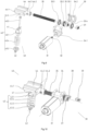
Fig. 1 is a schematic structural diagram showing that a roller of an electric auxiliary driving device according to Embodiment 1 of the invention is located at a retraction position; -
Fig. 2 is another schematic structural diagram showing that the roller of the electric auxiliary driving device according to Embodiment 1 of the invention is located at the retraction position; -
Fig. 3 is a schematic structural diagram showing that the roller of the electric auxiliary driving device according to Embodiment 1 of the invention is located at a working position; -
Fig. 4 is another schematic structural diagram showing that the roller of the electric auxiliary driving device according to Embodiment 1 of the invention is located at the working position; -
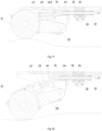
Fig. 5 is a sectional view showing that the roller of the electric auxiliary driving device according to Embodiment 1 of the invention is located at the retraction position; -
Fig. 6 is a sectional view showing that the roller of the electric auxiliary driving device according to Embodiment 1 of the invention is located at the working position; -
Fig. 7 is a sectional view of the working position at which the roller of the electric auxiliary driving device according to Embodiment 1 of the invention meets a protrusion on the ground; -
Fig. 8 is a sectional view of the working position at which the roller of the electric auxiliary driving device according to Embodiment 1 of the invention meets a recess on the ground; -
Fig. 9 is an exploded view of the electric auxiliary driving device according to Embodiment 1 of the invention; -
Fig. 10 is another exploded view of the electric auxiliary driving device according to Embodiment 1 of the invention; -
Fig. 11 is a schematic structural diagram of an electric auxiliary driving device according to Embodiment 2 of the invention; -
Fig. 12 is another schematic structural diagram of the electric auxiliary driving device according to Embodiment 2 of the invention; -
Fig. 13 is a schematic structural diagram of an inserting pin of the electric auxiliary driving device according to Embodiment 2 of the invention; -
Fig. 14 is a schematic structural diagram of an inserting seat of the electric auxiliary driving device according to Embodiment 2 of the invention; -
Fig. 15 is a sectional view showing that a roller of the electric auxiliary driving device according to Embodiment 2 of the invention is located at a retraction position; -
Fig. 16 is a sectional view showing that the roller of the electric auxiliary driving device according to Embodiment 2 of the invention is located at a working position; -
Fig. 17 is a sectional view of the working position at which the roller of the electric auxiliary driving device according to Embodiment 2 of the invention meets a protrusion on the ground; and -
Fig. 18 is a sectional view of the working position at which the roller of the electric auxiliary driving device according to Embodiment 2 of the invention meets a recess on the ground. - The above figures include the following reference numerals:
- 10, mounting support; 11, rocker bearing shaft; 12, guiding groove; 14, housing;
- 20, rocker; 21, roller; 22, roller shaft; 23, groove; 24, bearing fork; 25, web plate;
- 30, lifting device; 31, driving motor; 32, worm; 33, worm wheel; 33.1, second threaded hole; 33.2, external tooth; 33.3, first rolling bearing; 33.4, second rolling bearing; 34, worm wheel housing; 34.1, first worm wheel half-housing; 34.2, second worm wheel half-housing; 35, second spindle; 37, shifting cam ring; 38, first limiting switch; 39, second limiting switch;
- 40, balancing device; 41, upper spring support rod bearing; 42, lower spring support rod bearing; 43, spring support rod; 43.1, upper spring support rod head; 43.2, lower spring support rod head; 43.3, spring support rod shaft; 43.4, first compression spring; 44, sliding block; 44.1, linear guide rail; 44.2, lining; 44.3, fixing hole; 45, inserting seat; 46, inserting pin; 46.1, inserting pin rod; 46.2, inserting pin head; 47, limiting member;
- 50, pulling device; 51, third gear motor.
- Technical solutions of embodiments of the invention will be clearly and completely described below in conjunction with the accompanying drawings of the embodiments of the invention. Obviously, the embodiments described are merely some embodiments rather than all the embodiments of the invention. The following description of at least one illustrative embodiment is merely illustrative in nature and in no way serves as any limitation of the invention and its application or use. On the basis of the embodiments of the invention, all other embodiments obtained by those of ordinary skill in the art without making creative efforts fall within the protection scope of the invention.
- As shown in
Figs. 1-10 , Embodiment 1 of the invention provides an electric auxiliary driving device. The electric auxiliary driving device includes a mountingsupport 10, arocker 20, a pullingdevice 50, alifting device 30, and abalancing device 40. The mountingsupport 10 is fixedly connected with a furniture. A first end of therocker 20 is provided with arotatable roller 21. A second end of therocker 20 is hinged to the mountingsupport 10. The pullingdevice 50 is connected with therocker 20. The pullingdevice 50 is connected with theroller 21 in a driving manner. The liftingdevice 30 includes a driving device and a slidingblock 44 moving along a straight line. The driving device drives therocker 20 to rotate by driving the slidingblock 44 to move. The balancingdevice 40 includes aspring support rod 43. A first end of thespring support rod 43 is hinged to therocker 20. A second end of thespring support rod 43 is hinged to the slidingblock 44. - Through the technical solution of the invention, the electric auxiliary driving device includes the mounting
support 10, therocker 20, the pullingdevice 50, the liftingdevice 30 and thebalancing device 40. The mountingsupport 10 is fixedly connected with the furniture, and the driving device drives the slidingblock 44 to extend out of the mountingsupport 10 along the straight line. Further, the slidingblock 44 drives thespring support rod 43 to rotate, and thespring support rod 43 drives therocker 20 to rotate, such that theroller 21 is in contact with the ground. Then, the pullingdevice 50 drives theroller 21 to roll. In this way, the furniture can be driven to move by the electric auxiliary driving device, such that pressure generated when an operator moves the furniture can be reduced. The lifting device and the balancing device are connected by the slidingblock 44 moving linearly, and the slidingblock 44 moves linearly in a horizontal direction. Thus, a lifting function of the electric auxiliary driving device can be achieved in very small mounting space. Moreover, other parts of the electric auxiliary driving device are all arranged below the mountingsupport 10, reducing mounting space in a height direction. - Moreover, the electric auxiliary driving device of the invention is particularly applied to beds in hospitals and sanatoriums. The electric auxiliary driving device is added to a mobile hospital bed firmly supported by at least 3 casters. In the above configuration, fixed casters cannot guarantee permanent contact with the ground. Thus, in addition to the
lifting device 30 configured to temporarily lower or raise theroller 21, the balancingdevice 40 is further provided, such that theroller 21 is kept in constant contact with the ground. - In the embodiment, an upper surface of the mounting
support 10 is fixedly connected with a lower surface of the furniture, therocker 20 is located in a rear zone below the mountingsupport 10, the pullingdevice 50 is located at one side of therocker 20 and connected with the side of therocker 20, and thelifting device 30 is located in a front zone below the mountingsupport 10. With arrangement of the above structure, after theroller 21 is retracted, the roller can be completely located in the rear zone below the mountingsupport 10. By excluding a wall thickness of a furniture baseplate or a height of a support at a top of the mountingsupport 10, a minimum height of the electric auxiliary driving device in the invention is completely determined by a diameter of theroller 21 after theroller 21 is retracted. In this way, an avoidance groove in a central zone of the mountingsupport 10 can also be designed so as to accommodate the roller, such that the minimum height of the electric auxiliary driving device corresponds to the diameter of theroller 21. - It should be noted that with the lifting
device 30, therocker 20 can firstly rotate downward around a hinge point to the mountingsupport 10, such that the rocker can enter its driving position so as to enable theroller 21 to be in contact with the ground. Then, the balancingdevice 40 may compensate for an uneven part, for instance, a protrusion and a recess, of the ground at the position, such that theroller 21 is always kept in contact with the ground. - As shown in
Figs. 2 and5 , the balancingdevice 40 further includes a guiding structure. The guiding structure extends along the straight line. The guiding structure includes a guiding element and a guidinggroove 12. The guiding element is inserted into the guidinggroove 12. The guidinggroove 12 is provided on one of the mountingsupport 10 or the slidingblock 44. The guiding element is arranged on the other one of the mountingsupport 10 or the slidingblock 44. The guiding structure can be configured to guide the slidingblock 44, and the slidingblock 44 can move in an extension direction of the guiding structure, such that the slidingblock 44 will not deflect, and normal operation of thebalancing device 40 and therocker 20 can be ensured. - As shown in
Figs. 4 and5 , the guiding element includes a linear guide rail 44.1 arranged on a side wall of the slidingblock 44, a side wall of the mountingsupport 10 is provided with two parallel guiding plates, and a space between the two guiding plates forms the guidinggroove 12. The guiding element and the guidinggroove 12 of the above structure have advantages of simple structure and convenient processing. - In other embodiments, the guiding element includes a linear guide rail 44.1 arranged on a bottom wall of the sliding
block 44, a bottom wall of the mountingsupport 10 is provided with two parallel guiding ribs, and a space between the two guiding ribs forms the guidinggroove 12. With the above structure, advantages of simple structure and convenient processing are achieved. - In the embodiment, the driving device includes a driving
motor 31 and asecond spindle 35 connected with the drivingmotor 31 in a driving manner. Thesecond spindle 35 is connected with the slidingblock 44 and drives the slidingblock 44 to move along the straight line. With the driving device of the above structure, the drivingmotor 31 can drive thesecond spindle 35, and thesecond spindle 35 can drive the slidingblock 44 to move along the straight line, such that advantages of simple driving structure and simple transmission structure are achieved. - Specifically, a second end of the sliding
block 44 is provided with a lining 44.2. The lining 44.2 is provided with a fixing hole 44.3. A first end of thesecond spindle 35 is inserted into the lining 44.2. Thesecond spindle 35 and the slidingblock 44 are connected by inserting a fixing pin into the fixing hole. - In other embodiments, the driving device includes a first gear motor and a first spindle. The first gear motor drives the first spindle to rotate. The first spindle is provided with an external thread. The sliding
block 44 is provided with a first threaded hole. The external thread is connected with the first threaded hole in a threaded manner. With the above structure, rotary motion of the first spindle can be converted into linear motion of the slidingblock 44, achieving an advantage of simple structure. - As shown in
Figs. 8 and9 , the liftingdevice 30 further includes aworm wheel 33 and aworm 32 that are capable of rotating relatively and cooperating with each other. The drivingmotor 31 includes a second gear motor. An output end of the second gear motor is connected with theworm 32 in a driving manner. Teeth of theworm 32 are engaged with external teeth 33.2 of theworm wheel 33. Theworm wheel 33 is provided with a second threaded hole 33.1. Thesecond spindle 35 penetrates the second threaded hole 33.1 and is connected with theworm wheel 33 in a threaded manner. Through cooperation of theworm wheel 33 and theworm 32, rotary motion of an output shaft of the gear motor can be converted into linear motion of thesecond spindle 35, achieving advantages of simple transmission structure and high reliability. - In the embodiment, a shifting
cam ring 37 is sleeved on a second end of thesecond spindle 35. Extension or retraction of thesecond spindle 35 is implemented through alternate cooperation of the shiftingcam ring 37 with a first limitingswitch 38 or a second limitingswitch 39. - Specifically, under the control of an electronic module, the driving
motor 31 drives thesecond spindle 35 to extend out of the mountingsupport 10. Meanwhile, thesecond spindle 35 drives the slidingblock 44 to move. The slidingblock 44 drives therocker 20 to rotate by thespring support rod 43, and therocker 20 rotates to drive theroller 21 to be in contact with the ground. In this case, the shiftingcam ring 37 abuts against the first limitingswitch 38, and thesecond spindle 35 stops extending and is fixed. When theroller 21 needs to be retracted, under the control of the electronic module, the drivingmotor 31 drives thesecond spindle 35 to retract into the mountingsupport 10. Further, thespring support rod 43 drives therocker 20 to rotate reversely, and therocker 20 rotates to drive theroller 21 to be retracted. - As shown in
Figs. 8 and9 , the liftingdevice 30 further includes aworm wheel housing 34 fixedly connected with the mountingsupport 10. Theworm wheel 33 is arranged in theworm wheel housing 34. Theworm wheel housing 34 can protect theworm wheel 33 and theworm 32, such that influence on theworm wheel 33 and theworm 32 can be avoided in a transmission process, making transmission precision higher. - In the embodiment, the lifting
device 30 further includes a first rolling bearing 33.3 and a second rolling bearing 33.4. Theworm wheel housing 34 includes a first worm wheel half-housing 34.1 and a second worm wheel half-housing 34.2 connected to each other. An inner ring of the first rolling bearing 33.3 and an inner ring of the second rolling bearing 33.4 are sleeved on two ends of theworm wheel 33 respectively. The first worm wheel half-housing 34.1 and the second worm wheel half-housing 34.2 are configured to fasten outer rings of the first rolling bearing 33.3 and the second rolling bearing 33.4. With the first rolling bearing 33.3 and the second rolling bearing 33.4, theworm wheel 33 can be centered, and a rotation process of theworm wheel 33 is smoother. - Specifically, a bottom wall of the mounting
support 10 is further connected with ahousing 14. The drivingmotor 31, theworm wheel 33 and theworm 32 are all located in a space defined by the mountingsupport 10 and thehousing 14. In addition, when the roller is at the retraction position, thesecond spindle 35 is also located in the space defined by the mountingsupport 10 and thehousing 14. Thehousing 14 can be configured to protect the above components. - As shown in
Figs. 5-9 , thespring support rod 43 includes a spring support rod shaft 43.3, an upper spring support rod head 43.1 and a lower spring support rod head 43.2. An upper end of the spring support rod shaft 43.3 is inserted into a first end of the upper spring support rod head 43.1. A second end of the upper spring support rod head 43.1 is hinged to the slidingblock 44. A first end of the lower spring support rod head 43.2 is hinged to therocker 20. A second end of the lower spring support rod head 43.2 is connected with a lower end of the spring support rod shaft 43.3. With thespring support rod 43 of the above structure, the spring support rod shaft 43.3 can slide in the upper spring support rod head 43.1, and the electric auxiliary driving device can adapt to the recess or the protrusion on the ground, such that theroller 21 can be always kept in contact with the ground, and a use scope of the electric auxiliary driving device can be enlarged. - In the embodiment, the balancing
device 40 further includes a first compression spring 43.4 sleeved on a periphery of the spring support rod shaft 43.3. The first compression spring 43.4 is sandwiched between the upper spring support rod head 43.1 and the lower spring support rod head 43.2. The first compression spring 43.4 can achieve a buffering effect, such that thespring support rod 43 can move quickly in the upper spring support rod head 43.1 and the lower spring support rod head 43.2 under an elastic force of the spring when theroller 21 meets the recess or the protrusion on the ground. Further, therocker 20 rotates quickly for a response, such that theroller 21 can always abut against the ground. - It should be noted that the
balancing device 40 further includes an upper spring support rod bearing 41, a lower spring support rod bearing 42, a first articulated shaft and a second articulated shaft. The second end of the upper spring support rod head 43.1 is hinged to the slidingblock 44 through the first articulated shaft. An inner ring of the upper spring support rod bearing 41 is sleeved on a periphery of the first articulated shaft. An outer ring of the upper spring support rod bearing 41 is sleeved on the second end of the upper spring support rod head 43.1. The first end of the lower spring support rod head 43.2 is hinged to therocker 20 through the second articulated shaft. An inner ring of the lower spring support rod bearing 42 is sleeved on a periphery of the second articulated shaft. An outer ring of the lower spring support rod bearing 42 is sleeved on the first end of the lower spring support rod head 43.2. With thebalancing device 40 of the above structure, the upper spring support rod head 43.1 and the lower spring support rod head 43.2 can rotate more smoothly. - In the embodiment, the spring support rod shaft 43.3 includes a tap bolt. The upper spring support rod head 43.1 is provided with a first stepped hole in a penetrating manner. A bolt head of the tap bolt is movably inserted into the first stepped hole. A bolt shank of the tap bolt is connected with the lower spring support rod head 43.2. When the upper spring support rod head 43.1 has a maximum distance from the lower spring support rod head 43.2, the bolt head of the tap bolt abuts against a stepped surface of the first stepped hole. The spring support rod shaft 43.3 is formed by the tap bolt, achieving advantages of convenient material acquisition and low cost.
- Specifically, the tap bolt includes a reaming bolt. A threaded shank of the reaming bolt is connected with the lower spring support rod head 43.2. With the above structure, a lower end of the reaming bolt can form a fixed end, and an upper end of the reaming bolt can form a moving end, such that the reaming bolt can conveniently move in the upper spring support rod head 43.1, so as to guide the
rocker 20. - As shown in
Fig. 5 , when theroller 21 is at the retraction position, thesecond spindle 35 is at a front end of the mountingsupport 10, and the slidingblock 44 drives the upper spring support rod head 43.1 to be located close to theworm wheel 33. In this case, the upper spring support rod head 43.1 has the maximum distance from the lower spring support rod head 43.2, the spring support rod shaft 43.3 abuts against the stepped surface of the first stepped hole, and thespring support rod 43 drives the first end of therocker 20 to be located close to the mountingsupport 10. In this way, a containment effect on therocker 20 is achieved, and theroller 21 can be retracted. - As shown in
Fig. 6 , when the electric auxiliary driving device works, the drivingmotor 31 drives theworm 32 to rotate, such that theworm 32 drives theworm wheel 33 to rotate, then thesecond spindle 35 is driven to move to a rear end of the mountingsupport 10, and thesecond spindle 35 drives the slidingblock 44 to move in an extension direction of the guiding structure. Further, the slidingblock 44 drives the upper spring support rod head 43.1 to move along the straight line, and thespring support rod 43 drives therocker 20 to rotate under the elastic force of the first compression spring 43.4. In this way, theroller 21 abuts against the ground, and meanwhile, the pulling device drives theroller 21 to rotate, such that the electric auxiliary driving device can drive the furniture to move. In this case, the first compression spring 43.4 is in a compressed state. - As shown in
Fig. 7 , when theroller 21 meets the protrusion on the ground, theroller 21 moves upward to drive therocker 20 to rotate upward. As the spring support rod shaft 43.3 is connected with the lower spring support rod head 43.2, the upper end of the spring support rod shaft 43.3 moves upward along the upper spring support rod head 43.1 until the upper end of the spring support rod shaft 43.3 abuts against the first articulated shaft, such that upper end limiting of the spring support rod shaft 43.3 is implemented. In this case, the first compression spring 43.4 is in a compressed state. Moreover, as the spring support rod shaft 43.3 fails to continue to move upward, therocker 20 cannot drive theroller 21 to move upward. A maximum height of the protrusion on the ground that can be compensated by theroller 21 is 20 mm. - As shown in
Fig. 8 , when theroller 21 meets the recess on the ground, theroller 21 moves downward to drive therocker 20 to rotate downward. As the spring support rod shaft 43.3 is connected with the lower spring support rod head 43.2, the upper end of the spring support rod shaft 43.3 can move downward along the upper spring support rod head 43.1 until the upper end of the spring support rod shaft 43.3 abuts against the stepped surface of the first stepped hole, such that lower end limiting of the spring support rod shaft 43.3 is implemented. In this case, as the spring support rod shaft 43.3 fails to continue to move downward, therocker 20 cannot drive theroller 21 to move downward. A maximum height of the recess on the ground that can be compensated by theroller 21 is 20 mm. - In the embodiment, the maximum height of the recess or the protrusion on the ground that can be compensated by the
roller 21 is 20 mm. Clearly, an actual compensation value can be changed according to parameters such as a distance between limiting switches, an extension length of thespring support rod 43 or a mounting position of the auxiliary driving device. - It should be noted that when the auxiliary driving device needs to reduce pressure of workers, the
second spindle 35 is always in a state of extending out of the rear end of the mountingsupport 10. - In addition, an additional vertical shaft can be designed to enable the
roller 21 to turn. Clearly, the auxiliary driving device can also be provided with one or more rollers. For instance, two parallel and spacedrollers 21 are designed, and eachroller 21 is provided with a separate motor. Alternatively, two auxiliary drivers are arranged as a pair in a spaced manner. Turning can also be implemented by controlling an electric motor located outside a curve to rotate faster than the other electric motor. - It should be noted that all types of electric motors can be regarded as driving
motors 31. A gear motor provided with theworm wheel 33 is preferred. In addition, a gearless motor of a brushless direct current motor type can also be used. - As shown in
Fig. 4 , therocker 20 includes a connecting section and abearing fork 24 connected to each other. The bearingfork 24 includes two bearing fork arms arranged at two sides of theroller 21 respectively. The pullingdevice 50 is connected with one of the bearing fork arms. Theroller 21 is provided with aroller shaft 22. One end of theroller shaft 22 is rotatably connected with the bearingfork 24. An output end of the pullingdevice 50 is connected with the other end of theroller shaft 22 in a driving manner. With therocker 20 of the above structure, advantages of simple connection structure and convenient assembly are achieved. Moreover, with the bearingfork 24 designed with the two bearing fork arms, stress on two sides of theroller 21 can be more uniform. - In the embodiment, a second end of the connecting section is hinged to the mounting
support 10. - As shown in
Figs. 4 and5 , the electric auxiliary driving device further includes arocker bearing shaft 11. The mountingsupport 10 is hinged to the second end of therocker 20 through therocker bearing shaft 11. Thespring support rod 43 is movably arranged between theroller 21 and therocker bearing shaft 11. The mountingsupport 10 can be hinged to therocker 20 by therocker bearing shaft 11, achieving an advantage of simple structure. - Specifically, the
rocker 20 further includes aweb plate 25. The two bearing fork arms are connected through one side of theweb plate 25. The other side of theweb plate 25 is connected with the connecting section. The connecting section and thebearing fork 24 are connected by theweb plate 25, achieving an advantage of simple connection structure. - In the embodiment, the connecting section is provided with a
groove 23 disposed obliquely downwards. The first end of thespring support rod 43 is inserted into thegroove 23. Thegroove 23 can avoid thespring support rod 43, achieving an advantage of convenient arrangement. - Specifically, a first end of the spring support rod shaft 43.3 and the lower spring support rod head 43.2 are both located in the
groove 23. - The mounting
support 10 is provided with a stopper. The stopper abuts against the bearingfork 24 so as to limit a rotation angle of therocker 20. With the stopper, therocker 20 can be limited when therocker 20 is at the retraction position, thus protecting theroller 21. - In the embodiment, the pulling
device 50 includes athird gear motor 51. Thethird gear motor 51 and a transmission device are transversely arranged on a left arm of the bearingfork 24. Thus, output of thethird gear motor 51 is directly applied to theroller shaft 22. - Embodiment 2 of the invention provides an electric auxiliary driving device. Embodiment 2 and Embodiment 1 are different in that, in Embodiment 2, as shown in
Figs. 11-14 , thespring support rod 43 includes an insertingseat 45 and an insertingpin 46, a first end of the insertingseat 45 is hinged to therocker 20, a first end of the insertingpin 46 is inserted into a second end of the insertingseat 45, and a second end of the insertingpin 46 is hinged to a slidingblock 44. Through cooperation between the insertingseat 45 and the insertingpin 46, the insertingpin 46 can slide in the insertingseat 45, and the electric auxiliary driving device can adapt to a recess or a protrusion on the ground, such that theroller 21 can be always kept in contact with the ground, and a use scope of the electric auxiliary driving device can be enlarged. - In the embodiment, the balancing
device 40 further includes a second compression spring sleeved on a periphery of thespring support rod 43, and the second compression spring is sandwiched between the insertingseat 45 and the insertingpin 46. The second compression spring can achieve a buffering effect, such that thespring support rod 43 can move quickly in the upper spring support rod head 43.1 and the lower spring support rod head 43.2 under an elastic force of the spring when theroller 21 meets the recess or the protrusion on the ground. Further, therocker 20 rotates quickly for a response, such that theroller 21 can always abut against the ground. - As shown in
Figs. 11-14 , thespring support rod 43 further includes a limitingmember 47 connected with the first end of the insertingpin 46. The insertingpin 46 includes an inserting pin rod 46.1 and an inserting pin head 46.2 connected to each other. The first end of the insertingseat 45 is hinged to therocker 20. The second end of the insertingseat 45 is provided with a second stepped hole. The inserting pin rod 46.1 is movably inserted into the second stepped hole. A second end of the inserting pin head 46.2 is hinged to the slidingblock 44. When the inserting pin head 46.2 has a maximum distance from the insertingseat 45, the limitingmember 47 abuts against a stepped surface of the second stepped hole. When the inserting pin head 46.2 has a minimum distance from the insertingseat 45, the inserting pin head 46.2 abuts against the insertingseat 45. With the above structure, an upper end of the inserting pin rod 46.1 forms a fixed end, and a lower end of the inserting pin rod forms a moving end, such that the inserting pin rod 46.1 moves conveniently in the insertingseat 45, so as to guide therocker 20. - As shown in
Fig. 15 , when theroller 21 is at the retraction position, the inserting pin head 46.2 has the maximum distance from the insertingseat 45, and the limitingmember 47 abuts against the stepped surface of the second stepped hole, such that a containment effect on therocker 20 is achieved, and theroller 21 is retracted. - As shown in
Fig. 16 , when the electric auxiliary driving device works, theroller 21 abuts against the ground, and the inserting pin rod 46.1 moves in the insertingseat 45, such that the electric auxiliary driving device adapts to changing conditions of the ground at any time. - As shown in
Fig. 17 , when theroller 21 meets the protrusion on the ground, the inserting pin head 46.2 has the minimum distance from the insertingseat 45, and the inserting pin head 46.2 abuts against the insertingseat 45, such that a rotation angle of therocker 20 is limited, and theroller 21 can compensate for the protrusion on the ground. - As shown in
Fig. 18 , when theroller 21 meets the recess on the ground, the inserting pin head 46.2 has the maximum distance from the insertingseat 45, and the limitingmember 47 abuts against the stepped surface of the second stepped hole, such that a rotation angle of therocker 20 is limited, and theroller 21 can compensate for the recess on the ground. - Embodiment 3 of the invention provides a hospital bed. The hospital bed includes a bed body and an electric auxiliary driving device. A mounting support of the electric auxiliary driving device is connected with the bed body. The electric auxiliary driving device includes the above-mentioned electric auxiliary driving device. According to the hospital bed with the electric auxiliary driving device, the lifting device and the balancing device are connected by the sliding
block 44 moving linearly, and the slidingblock 44 moves linearly in a horizontal direction. Thus, a lifting function of the electric auxiliary driving device can be achieved in a very small mounting space. Moreover, other parts of the electric auxiliary driving device are all arranged below the mountingsupport 10, reducing mounting space in a height direction.
Claims (16)
- An electric auxiliary driving device, comprising:a mounting support (10) fixedly connected with a furniture;a rocker (20), wherein a first end of the rocker (20) is provided with a rotatable roller (21), and a second end of the rocker (20) is hinged to the mounting support (10);a pulling device (50) connected with the rocker (20), wherein the pulling device (50) is connected with the roller (21) in a driving manner;a lifting device (30) comprising a driving device and a sliding block (44) moving along a straight line, wherein the driving device drives the rocker (20) to rotate by driving the sliding block (44) to move; anda balancing device (40) comprising a spring support rod (43), wherein a first end of the spring support rod (43) is hinged to the rocker (20), and a second end of the spring support rod (43) is hinged to the sliding block (44).
- The electric auxiliary driving device according to claim 1, wherein the balancing device (40) further comprises a guiding structure, the guiding structure extends along the straight line, the guiding structure comprises a guiding element and a guiding groove (12), the guiding element is inserted into the guiding groove (12), the guiding groove (12) is provided on one of the mounting support (10) or the sliding block (44), and the guiding element is arranged on the other one of the mounting support (10) or the sliding block (44).
- The electric auxiliary driving device according to claim 2, whereinthe guiding element comprises a linear guide rail (44.1) arranged on a side wall of the sliding block (44), the mounting support (10) is provided with two parallel guiding plates, and a space between the two guiding plates forms the guiding groove (12); and alternatively,the guiding element comprises a linear guide rail (44.1) arranged on a bottom wall of the sliding block (44), the mounting support (10) is provided with two parallel guiding ribs, and a space between the two guiding ribs forms the guiding groove (12).
- The electric auxiliary driving device according to claim 1, wherein the driving device comprises a first gear motor and a first spindle, the first gear motor drives the first spindle to rotate, the first spindle is provided with an external thread, the sliding block (44) is provided with a first threaded hole, and the external thread is connected with the first threaded hole in a threaded manner.
- The electric auxiliary driving device according to claim 1, wherein the driving device comprises a driving motor (31) and a second spindle (35) connected with the driving motor (31) in a driving manner, and the second spindle (35) is connected with the sliding block (44) and drives the sliding block (44) to move along the straight line.
- The electric auxiliary driving device according to claim 5, wherein the lifting device (30) further comprises a worm wheel (33) and a worm (32) that are capable of rotating relatively and cooperating with each other, the driving motor (31) comprises a second gear motor, an output end of the second gear motor is connected with the worm (32) in a driving manner, teeth of the worm (32) are engaged with external teeth (33.2) of the worm wheel (33), the worm wheel (33) is provided with a second threaded hole (33.1), and the second spindle (35) penetrates the second threaded hole (33.1) and is connected with the worm wheel (33) in a threaded manner.
- The electric auxiliary driving device according to claim 6, whereinthe lifting device (30) further comprises a worm wheel housing (34) fixedly connected with the mounting support (10), and the worm wheel (33) is arranged in the worm wheel housing (34); andthe lifting device (30) further comprises a first rolling bearing (33.3) and a second rolling bearing (33.4), the worm wheel housing (34) comprises a first worm wheel half-housing (34.1) and a second worm wheel half-housing (34.2) connected to each other, an inner ring of the first rolling bearing (33.3) and an inner ring of the second rolling bearing (33.4) are sleeved on two ends of the worm wheel (33) respectively, and the first worm wheel half-housing (34.1) and the second worm wheel half-housing (34.2) are configured to fasten outer rings of the first rolling bearing (33.3) and the second rolling bearing (33.4).
- The electric auxiliary driving device according to claim 1, whereinthe spring support rod (43) comprises a spring support rod shaft (43.3), an upper spring support rod head (43.1) and a lower spring support rod head (43.2), an upper end of the spring support rod shaft (43.3) is inserted into a first end of the upper spring support rod head (43.1), a second end of the upper spring support rod head (43.1) is hinged to the sliding block (44), a first end of the lower spring support rod head (43.2) is hinged to the rocker (20), and a second end of the lower spring support rod head (43.2) is connected with a lower end of the spring support rod shaft (43.3); andthe balancing device (40) further comprises a first compression spring (43.4) being sleeved on a periphery of the spring support rod shaft (43.3), and the first compression spring (43.4) is sandwiched between the upper spring support rod head (43.1) and the lower spring support rod head (43.2).
- The electric auxiliary driving device according to claim 8, wherein the balancing device (40) further comprises an upper spring support rod bearing (41), a lower spring support rod bearing (42), a first articulated shaft and a second articulated shaft, the second end of the upper spring support rod head (43.1) is hinged to the sliding block (44) through the first articulated shaft, an inner ring of the upper spring support rod bearing (41) is sleeved on a periphery of the first articulated shaft, an outer ring of the upper spring support rod bearing (41) is sleeved on the second end of the upper spring support rod head (43.1), the first end of the lower spring support rod head (43.2) is hinged to the rocker (20) through the second articulated shaft, an inner ring of the lower spring support rod bearing (42) is sleeved on a periphery of the second articulated shaft, and an outer ring of the lower spring support rod bearing (42) is sleeved on the first end of the lower spring support rod head (43.2).
- The electric auxiliary driving device according to claim 9, wherein the spring support rod shaft (43.3) comprises a tap bolt, the upper spring support rod head (43.1) is provided with a first stepped hole in a penetrating manner, a bolt head of the tap bolt is movably inserted into the first stepped hole, a bolt shank of the tap bolt is connected with the lower spring support rod head (43.2), and when the upper spring support rod head (43.1) has a maximum distance from the lower spring support rod head (43.2), the bolt head of the tap bolt abuts against a stepped surface of the first stepped hole.
- The electric auxiliary driving device according to claim 10, wherein the tap bolt comprises a reaming bolt, and a threaded shank of the reaming bolt is connected with the lower spring support rod head (43.2).
- The electric auxiliary driving device according to claim 1, whereinthe spring support rod (43) comprises an inserting seat (45) and an inserting pin (46), a first end of the inserting seat (45) is hinged to the rocker (20), a first end of the inserting pin (46) is inserted into a second end of the inserting seat (45), and a second end of the inserting pin (46) is hinged to the sliding block (44); andthe balancing device (40) further comprises a second compression spring sleeved on a periphery of the spring support rod (43), and the second compression spring is sandwiched between the inserting seat (45) and the inserting pin (46).
- The electric auxiliary driving device according to claim 12, wherein the spring support rod (43) further comprises a limiting member (47) connected with the first end of the inserting pin (46), the inserting pin (46) comprises an inserting pin rod (46.1) and an inserting pin head (46.2) connected to each other, the first end of the inserting seat (45) is hinged to the rocker (20), the second end of the inserting seat (45) is provided with a second stepped hole, the inserting pin rod (46.1) is movably inserted into the second stepped hole, a second end of the inserting pin head (46.2) is hinged to the sliding block (44), when the inserting pin head (46.2) has a maximum distance from the inserting seat (45), the limiting member (47) abuts against a stepped surface of the second stepped hole, and when the inserting pin head (46.2) has a minimum distance from the inserting seat (45), the inserting pin head (46.2) abuts against the inserting seat (45).
- The electric auxiliary driving device according to claim 1, wherein the rocker (20) comprises a connecting section and a bearing fork (24) connected to each other, the bearing fork (24) comprises two bearing fork arms arranged at two sides of the roller (21) respectively, the pulling device (50) is connected with one of the bearing fork arms, the roller (21) is provided with a roller shaft (22), one end of the roller shaft (22) is rotatably connected with the bearing fork (24), and an output end of the pulling device (50) is connected with the other end of the roller shaft (22) in a driving manner.
- The electric auxiliary driving device according to claim 14, whereinthe electric auxiliary driving device further comprises a rocker bearing shaft (11), wherein the mounting support (10) is hinged to the second end of the rocker (20) through the rocker bearing shaft (11), and the spring support rod (43) is movably arranged between the roller (21) and the rocker bearing shaft (11);the rocker (20) further comprises a web plate (25), the two bearing fork arms are connected through one side of the web plate (25), and the other side of the web plate (25) is connected with the connecting section;the connecting section is provided with a groove (23) disposed obliquely downwards, and the first end of the spring support rod (43) is inserted into the groove (23); andthe mounting support (10) is provided with a stopper, and the stopper abuts against the bearing fork (24) so as to limit a rotation angle of the rocker (20).
- A hospital bed, comprising:a bed body; andan electric auxiliary driving device, wherein a mounting support of the electric auxiliary driving device is connected with the bed body, and the electric auxiliary driving device comprises the electric auxiliary driving device according to any one of claims 1-15.
Applications Claiming Priority (2)
| Application Number | Priority Date | Filing Date | Title |
|---|---|---|---|
| CN202210719281.0A CN117297894A (en) | 2022-06-23 | 2022-06-23 | Electric auxiliary drive device and hospital bed having the same |
| PCT/CN2023/088749 WO2023246253A1 (en) | 2022-06-23 | 2023-04-17 | Electric auxiliary driving apparatus and hospital bed with same |
Publications (2)
| Publication Number | Publication Date |
|---|---|
| EP4537801A1 true EP4537801A1 (en) | 2025-04-16 |
| EP4537801A4 EP4537801A4 (en) | 2025-10-01 |
Family
ID=89235921
Family Applications (1)
| Application Number | Title | Priority Date | Filing Date |
|---|---|---|---|
| EP23825906.3A Pending EP4537801A4 (en) | 2022-06-23 | 2023-04-17 | ELECTRIC AUXILIARY DRIVE DEVICE AND HOSPITAL BED WITH IT |
Country Status (5)
| Country | Link |
|---|---|
| US (1) | US20250381799A1 (en) |
| EP (1) | EP4537801A4 (en) |
| JP (1) | JP2025519790A (en) |
| CN (1) | CN117297894A (en) |
| WO (1) | WO2023246253A1 (en) |
Family Cites Families (17)
| Publication number | Priority date | Publication date | Assignee | Title |
|---|---|---|---|---|
| DE19539487A1 (en) * | 1995-10-24 | 1997-04-30 | Alber Ulrich Gmbh | Drive and brake assist device for wheelchairs |
| US6330926B1 (en) * | 1999-09-15 | 2001-12-18 | Hill-Rom Services, Inc. | Stretcher having a motorized wheel |
| DE29919214U1 (en) * | 1999-11-03 | 2000-01-05 | Dewert Antriebs- und Systemtechnik GmbH & Co KG, 32278 Kirchlengern | Electromotive furniture drive |
| US7014000B2 (en) * | 2000-05-11 | 2006-03-21 | Hill-Rom Services, Inc. | Braking apparatus for a patient support |
| DE102006007377A1 (en) * | 2006-02-17 | 2007-08-30 | Tente Gmbh & Co. Kg | Hospital bed with another in contact with the ground optionally driven additional role |
| US8746710B2 (en) * | 2010-05-17 | 2014-06-10 | Linet Spol S.R.O. | Patient support apparatus having an auxiliary wheel |
| DE102011000817A1 (en) * | 2011-02-18 | 2012-08-23 | Tente Gmbh & Co. Kg | additional role |
| US9908549B2 (en) * | 2015-08-18 | 2018-03-06 | Powerhandling Inc. | Dual motor drive system for a material handling device |
| CN105257127B (en) * | 2015-10-28 | 2023-06-02 | 江西百胜门控设备有限公司 | Lifting supporting wheel assembly and cantilever translation door |
| DE102016014566B4 (en) * | 2016-12-07 | 2019-03-14 | Grenzebach Maschinenbau Gmbh | Apparatus and method for the networked transport of patients or persons with reduced mobility, as well as a computer program and a machine-readable carrier |
| CN107625595A (en) * | 2017-09-27 | 2018-01-26 | 广州林腾生物科技有限公司 | A kind of multifunctional medicinal bed |
| CN111991149B (en) * | 2020-08-31 | 2022-07-12 | 浙江佑欣智能医疗科技有限公司 | Patient transfer bed with booster mechanism |
| CN112168519B (en) * | 2020-11-20 | 2024-11-15 | 河南奕恒医疗器械有限公司 | A multi-axis driven adaptive wheelchair |
| CN112720407B (en) * | 2020-12-21 | 2022-08-26 | 行星算力(深圳)科技有限公司 | Auxiliary wheel lifting mechanism and wheeled robot |
| CN215265798U (en) * | 2021-04-30 | 2021-12-21 | 中韶电气股份有限公司 | Box transformer convenient to remove |
| CN115320742B (en) * | 2022-02-08 | 2024-01-02 | 浙江理工大学 | Detachable wheel-foot type rescue robot |
| CN217566613U (en) * | 2022-06-23 | 2022-10-14 | 毕威泰克(浙江)医疗器械有限公司 | Electric auxiliary driving device and sickbed with same |
-
2022
- 2022-06-23 CN CN202210719281.0A patent/CN117297894A/en active Pending
-
2023
- 2023-04-17 US US18/878,145 patent/US20250381799A1/en active Pending
- 2023-04-17 JP JP2024574535A patent/JP2025519790A/en active Pending
- 2023-04-17 EP EP23825906.3A patent/EP4537801A4/en active Pending
- 2023-04-17 WO PCT/CN2023/088749 patent/WO2023246253A1/en not_active Ceased
Also Published As
| Publication number | Publication date |
|---|---|
| JP2025519790A (en) | 2025-06-26 |
| WO2023246253A1 (en) | 2023-12-28 |
| CN117297894A (en) | 2023-12-29 |
| US20250381799A1 (en) | 2025-12-18 |
| EP4537801A4 (en) | 2025-10-01 |
Similar Documents
| Publication | Publication Date | Title |
|---|---|---|
| US11395544B1 (en) | Keyboard tray that adjusts horizontally and vertically | |
| JP6055517B2 (en) | Operating table base for operating table | |
| JP2837366B2 (en) | Forging machine | |
| KR101361473B1 (en) | Device for controlling stroke of collision switch and medical diagnosis apparatus employing the same | |
| EP4537801A1 (en) | Electric auxiliary driving apparatus and hospital bed with same | |
| CN101214187A (en) | Lifting/lowering device for blood-drawing chair | |
| CN104084779A (en) | Multi-face jacking rotary plate achieving single-station operation | |
| CN217566613U (en) | Electric auxiliary driving device and sickbed with same | |
| CN201147445Y (en) | Lifting/lowering device for blood-drawing chair | |
| CN210144910U (en) | Intelligent nursing bed | |
| EP4647373A1 (en) | Material transfer apparatus | |
| AU2015101480A4 (en) | A snap spring assembling device for disc spring | |
| JP4170661B2 (en) | Mechanical press | |
| US9709209B2 (en) | Load support mechanism | |
| CN212469812U (en) | Drilling device for machining non-standard parts of mechanical equipment | |
| CN216352634U (en) | Bank self-service terminal | |
| CN219384618U (en) | Manual elevating gear of compression roller and adjustable compression roller | |
| JP2008535604A (en) | Method and apparatus for adjusting the mutual position of structural elements of a patient chair | |
| CN217297236U (en) | Cap screwing arm and cap screwing machine | |
| CN107692618B (en) | Tilt force adjusting device of office chair | |
| CN209682170U (en) | Mobile robot drives wheel lifter | |
| CN210826582U (en) | Big gear wheel supporting structure of circular knitting machine | |
| CN216318595U (en) | Brake device, shifting machine and rehabilitation training equipment | |
| CN210392610U (en) | Telescopic shear shank anti-blocking mechanism and burying conveying device | |
| CN223726008U (en) | Platform frame of adjustable direction |
Legal Events
| Date | Code | Title | Description |
|---|---|---|---|
| STAA | Information on the status of an ep patent application or granted ep patent |
Free format text: STATUS: THE INTERNATIONAL PUBLICATION HAS BEEN MADE |
|
| PUAI | Public reference made under article 153(3) epc to a published international application that has entered the european phase |
Free format text: ORIGINAL CODE: 0009012 |
|
| STAA | Information on the status of an ep patent application or granted ep patent |
Free format text: STATUS: REQUEST FOR EXAMINATION WAS MADE |
|
| 17P | Request for examination filed |
Effective date: 20250113 |
|
| AK | Designated contracting states |
Kind code of ref document: A1 Designated state(s): AL AT BE BG CH CY CZ DE DK EE ES FI FR GB GR HR HU IE IS IT LI LT LU LV MC ME MK MT NL NO PL PT RO RS SE SI SK SM TR |
|
| RAP3 | Party data changed (applicant data changed or rights of an application transferred) |
Owner name: BEWATEC (SHANGAI) MEDICAL DEVICES CO., LTD. Owner name: BEWATEC (ZHEJIANG) MEDICAL EQUIPMENT CO., LTD. |
|
| A4 | Supplementary search report drawn up and despatched |
Effective date: 20250901 |
|
| DAV | Request for validation of the european patent (deleted) | ||
| DAX | Request for extension of the european patent (deleted) | ||
| RIC1 | Information provided on ipc code assigned before grant |
Ipc: A61G 7/05 20060101AFI20250826BHEP Ipc: A61G 7/08 20060101ALI20250826BHEP |