EP4537684A1 - Heating device, aerosol generating device, and aerosol generating system - Google Patents
Heating device, aerosol generating device, and aerosol generating system Download PDFInfo
- Publication number
- EP4537684A1 EP4537684A1 EP23834928.6A EP23834928A EP4537684A1 EP 4537684 A1 EP4537684 A1 EP 4537684A1 EP 23834928 A EP23834928 A EP 23834928A EP 4537684 A1 EP4537684 A1 EP 4537684A1
- Authority
- EP
- European Patent Office
- Prior art keywords
- heating
- heating device
- cavity
- air guide
- tube portion
- Prior art date
- Legal status (The legal status is an assumption and is not a legal conclusion. Google has not performed a legal analysis and makes no representation as to the accuracy of the status listed.)
- Pending
Links
Images




Classifications
-
- A—HUMAN NECESSITIES
- A24—TOBACCO; CIGARS; CIGARETTES; SIMULATED SMOKING DEVICES; SMOKERS' REQUISITES
- A24F—SMOKERS' REQUISITES; MATCH BOXES; SIMULATED SMOKING DEVICES
- A24F40/00—Electrically operated smoking devices; Component parts thereof; Manufacture thereof; Maintenance or testing thereof; Charging means specially adapted therefor
- A24F40/40—Constructional details, e.g. connection of cartridges and battery parts
- A24F40/46—Shape or structure of electric heating means
-
- A—HUMAN NECESSITIES
- A24—TOBACCO; CIGARS; CIGARETTES; SIMULATED SMOKING DEVICES; SMOKERS' REQUISITES
- A24F—SMOKERS' REQUISITES; MATCH BOXES; SIMULATED SMOKING DEVICES
- A24F40/00—Electrically operated smoking devices; Component parts thereof; Manufacture thereof; Maintenance or testing thereof; Charging means specially adapted therefor
- A24F40/40—Constructional details, e.g. connection of cartridges and battery parts
- A24F40/48—Fluid transfer means, e.g. pumps
- A24F40/485—Valves; Apertures
-
- A—HUMAN NECESSITIES
- A24—TOBACCO; CIGARS; CIGARETTES; SIMULATED SMOKING DEVICES; SMOKERS' REQUISITES
- A24F—SMOKERS' REQUISITES; MATCH BOXES; SIMULATED SMOKING DEVICES
- A24F40/00—Electrically operated smoking devices; Component parts thereof; Manufacture thereof; Maintenance or testing thereof; Charging means specially adapted therefor
- A24F40/20—Devices using solid inhalable precursors
-
- A—HUMAN NECESSITIES
- A24—TOBACCO; CIGARS; CIGARETTES; SIMULATED SMOKING DEVICES; SMOKERS' REQUISITES
- A24F—SMOKERS' REQUISITES; MATCH BOXES; SIMULATED SMOKING DEVICES
- A24F40/00—Electrically operated smoking devices; Component parts thereof; Manufacture thereof; Maintenance or testing thereof; Charging means specially adapted therefor
- A24F40/40—Constructional details, e.g. connection of cartridges and battery parts
-
- A—HUMAN NECESSITIES
- A24—TOBACCO; CIGARS; CIGARETTES; SIMULATED SMOKING DEVICES; SMOKERS' REQUISITES
- A24F—SMOKERS' REQUISITES; MATCH BOXES; SIMULATED SMOKING DEVICES
- A24F40/00—Electrically operated smoking devices; Component parts thereof; Manufacture thereof; Maintenance or testing thereof; Charging means specially adapted therefor
- A24F40/40—Constructional details, e.g. connection of cartridges and battery parts
- A24F40/46—Shape or structure of electric heating means
- A24F40/465—Shape or structure of electric heating means specially adapted for induction heating
Definitions
- aerosol generating devices are increasingly more widely applied.
- the most important component in the aerosol generating device is a heating device, and an aerosol generation article is heated through the heating device, so that the aerosol generation article can generate smoke.
- a heating assembly is generally arranged at an air inlet end of the aerosol generation article for heating.
- the "mounting” includes fixing or limiting an element or a device to a specific position or place in a manner such as welding, screwing, snapping, or bonding.
- the element or the device may keep still at the specific position or place or move within a limited range.
- the element or the device may or may not be disassembled after being fixed or limited to the specific position or place, which is not limited in the embodiments of this application.
- the substantial attachment means that a distance L1 between the inner surface of the heat preservation assembly 10 and the circumferential outer surface of the aerosol generation article 2000 placed in the receiving cavity 11 is in a range of 0 mm ⁇ L1 ⁇ 2 mm. In some embodiments, the distance L1 satisfies 0.2 mm ⁇ L1 ⁇ 0.7 mm. In some embodiments, the distance L1 is 0.5 mm.
- the airflow heating assembly 20 is configured to heat a gas flowing through the airflow heating assembly 20, so that the heated gas heats the aerosol generation article 2000 placed in the receiving cavity 11.
- heat of the inner surface of the heat preservation assembly 10 heated by the airflow heating assembly 20 can be directly or indirectly transferred to an outer surface of the aerosol generation article 2000, so as to perform auxiliary heating on the aerosol generation article 2000 and make full use of the heat of the heat preservation assembly 10.
- the heating device 100 further includes a temperature measurement element 30.
- the temperature measurement element 30 is arranged inside the airflow heating assembly 20.
- the temperature measurement element 30 is configured to measure a temperature of the airflow heating assembly 20, so as to facilitate real-time monitoring and control of the temperature of the airflow heating assembly 20.
- the receiving cavity 11 is provided with a first chamber 111 and a second chamber 112, and the first chamber 111 and the second chamber 112 are in communication with each other along a first direction X.
- the first direction X is parallel to a center line of the heat preservation assembly 10.
- the first chamber 111 is configured to allow mounting of the airflow heating assembly 20, and the second chamber 112 is configured to allow mounting of the aerosol generation article 2000.
- the air guide element 21 is made of graphite, and the air guide element 21 has good thermal conductivity, which is beneficial to improve heating efficiency.
- the air guide element 21 is made of a graphite alloy.
- the graphite alloy has good magnetic conductivity and relatively high thermal conductivity.
- the good magnetic conductivity causes the heating element 22 to adopt an electromagnetic heating mode in addition to a resistive heating mode, so that the air guide element 21 can also generate heat, which increases an optional heating solution.
- the relatively high thermal conductivity can effectively reduce time required for the heating element 22 to heat the air guide element 21 to a predetermined temperature, so as to improve heating efficiency of the airflow heating assembly 20.
- the plurality of air guide channels 211 are in a shape of a cylinder, and a diameter D1 of each of the air guide channels 211 satisfies 0 ⁇ D1 ⁇ 0.5 mm.
- the number of air guide channels 211 may be increased, and on the other hand, the heating efficiency of the gas flowing through the air guide channels 211 may be improved, to prevent a gas flow from being large and a poor gas heating effect as a result of an excessively large diameter of the air guide channel 211.
- the air guide element 21 includes a first air guide block 213 and a second air guide block 214.
- the first air guide block 213 is provided with a first groove 2131
- the second air guide block 214 is provided with a second groove 2141.
- the first groove 2131 and the second groove 2141 jointly define the above second mounting groove 212.
- the air guide element 21 adopts a split design, which may help the temperature measurement element 30 to be mounted in the second mounting groove 212 more easily, and improve assembly efficiency of the heating device 100.
- a circumferential outer surface of the air guide element 21 is provided with a first mounting region 216 and a second mounting region 217.
- the first mounting region 216 is configured to connect to the inner surface of the inner tube portion 12 of the heat preservation assembly 10 through interference fit, and the air guide element 21 is fixed to the inner tube portion 12 under the action of friction.
- the first mounting region 216 is provided with a first protrusion 2161. The first protrusion 2161 abuts against the inner surface of the inner tube portion 12 of the heat preservation assembly 10 to form line contact or point contact.
- the first mounting region 216 may be connected to the inner tube portion 12 in another connection manner, such as bonding.
- the heating element 22 includes a resistive heating element 223, a first insulating layer 224, and a second insulating layer 225.
- the resistive heating element 223 is at least partially arranged on the outer peripheral surface of the air guide element 21, the first insulating layer 224 is arranged between the air guide element 21 and the resistive heating element 223, and the second insulating layer 225 is arranged between the resistive heating element 223 and the inner surface of the inner tube portion 12 of the heat preservation assembly 10.
- the resistive heating element 223 is electrically connected to the external power supply. When the external power supply supplies power to the resistive heating element 223, the resistive heating element 223 can generate heat, thereby heating the air guide element 21.
- the first insulating layer 224 and the second insulating layer 225 are also adhesive to fix the resistive heating element 223 and the air guide element 21 in the first chamber 111 of the receiving cavity 11. Specifically, the first insulating layer 224 fixes the air guide element 21 to the resistive heating element 223, and the second insulating layer 225 fixes the resistive heating element 223 to the inner tube portion 12 of the heat preservation assembly 10.
- the heating element 22 further includes a magnetic field shielding layer 228.
- the magnetic field shielding layer 228 is arranged between the induction coil 226 and the inner tube portion 12 of the heat preservation assembly 10.
- the magnetic field shielding layer 228 is configured to shield influence of the alternating magnetic field generated by the energized induction coil 226 on the inner tube portion 12, to reduce heat generated in the inner tube portion 12.
- the first mounting groove 215 provided with the heating member 229 and the second mounting groove 212 provided with the temperature measurement element 30 are both located in the center of the air guide element 21, the first mounting groove 215 and the second mounting groove 212 are the same mounting groove.
- the heating member 229 and the temperature measurement element 30 are both located in the mounting groove.
- the temperature measurement element 30 performs temperature measurement by using a temperature coefficient of resistance (TCR).
- TCR temperature coefficient of resistance
- the temperature measurement element 30 may further perform temperature measurement by using a negative temperature coefficient (NTC), a thermistor, and a thermocouple.
- the first thermal insulation member 23 is made of ZrO2 (zirconium dioxide) and a compound thereof, and the first thermal insulation member 23 has at least characteristics of high temperature resistance, low thermal conductivity, and corrosion resistance.
- the first thermal insulation member 23 may also be made of a thermal insulation material such as metal and/or non-metal and a compound thereof.
- the heat of the inner tube portion 12 can be transferred to part of the circumferential outer surface of the aerosol generation article 2000, to perform auxiliary heating on the aerosol generation article 2000, so that the aerosol generation article 2000 is heated more evenly.
- the heating device 100 in the embodiments of this application includes a heat preservation assembly 10 and an airflow heating assembly 20.
- the heat preservation assembly 10 is internally provided with a receiving cavity 11.
- the receiving cavity 11 is configured to accommodate an aerosol generation article 2000.
- the airflow heating assembly 20 is arranged in the receiving cavity 11.
- the airflow heating assembly 20 is configured to heat a gas flowing through the airflow heating assembly 20, so that the heated gas heats the aerosol generation article 2000 placed in the receiving cavity 11.
- an inner surface of the heat preservation assembly 10 is substantially attached to a circumferential outer surface of the aerosol generation article 2000, and heat of an inner wall surface of the heat preservation assembly 10 can be transferred to the circumferential outer surface of the aerosol generation article 2000 for auxiliary heating, so that the heat of the heat preservation assembly 10 is effectively used to heat an axial outer surface of the aerosol generation article 2000, and parts and components of the heating device 100 are reduced.
- the fourth through hole 204 is configured for exposure of part of the circuit device 300, so that the external power supply can be electrically connected to the circuit device 300.
- the fourth through hole 204 is further configured to allow an external gas to enter the first accommodating cavity 2011, so as to enter the heating device 100 to be heated.
- the charging interface 303 may not be provided, and the battery module 302 may use a detachable lithium battery, or the like.
- two or more PCB circuit boards 301 are arranged. The two or more PCB circuit boards 301 are stacked in parallel in the first accommodating cavity 2011, and the PCB circuit boards 301 and the sheath 400 are arranged in the first accommodating cavity 2011 in a left-to-right direction, so that a layout of the PCB circuit boards 301 and the sheath 400 is more reasonable.
- sealing treatment may be performed between the first accommodating cavity 2011 and the second accommodating cavity 2012 based on actual requirements, to prevent a gas generated by the air guide element 21 in the first accommodating cavity 2011 heating the aerosol generation article 2000 from entering the second accommodating cavity 2012 and affecting the operating performance of the battery module 302.
- the aerosol generating device 1000 further includes a second thermal insulation member 600.
- the second thermal insulation member 600 is arranged on a side of the end cap 500 facing the heating device 100, that is, the second thermal insulation member 600 is located between the air guide element 21 and the end cap 500.
- the second thermal insulation member 600 is made of a material with low thermal conductivity.
- the second thermal insulation member 600 is configured to reduce heat transferred from the air guide element 21 to the end cap 500.
- the second thermal insulation member 600 is provided with a third through hole 601 and a fourth convex rib 602.
- the second thermal insulation member 600 and the end cap 500 are arranged between the air guide element 21 and the cavity bottom of the first mounting cavity 401 for double thermal insulation, and the second thermal insulation member 600 is connected to the air guide element 21 and the end cap 500, and the end cap 500 is connected to the cavity bottom both in a manner of point contact, thereby effectively reducing the heat directly transferred by the air guide element 21 to the lower shell 403.
- the sheath 400 can operate in a relatively low temperature environment, thereby effectively prolonging a service life of the sheath 400.
- the heat loss of the air guide element 21 can be effectively reduced, and the thermal efficiency of the air guide element 21 is improved.
- the second thermal insulation member 600 and the end cap 500 may be integrally formed.
- the airflow heating assembly 20a is configured to heat the air flowing through the airflow channel 30a into hot air, and the hot air may flow into an interior of the aerosol generation article 2000 from a distal end of the aerosol generation article 2000 to heat a tobacco section in the aerosol generation article 2000 to generate an aerosol.
- the hot air may flow into the interior of the aerosol generation article 2000 from a side wall of the aerosol generation article 2000.
- An end of the tubular body 10a is provided with a first opening 111a, and at least part of the aerosol generation article 2000 is inserted into the containing cavity for accommodation through the first opening 111a.
- the end with the first opening in the tubular body is defined as a proximal end m1 of the heating device, and a distal end m2 of the heating device is arranged opposite to the proximal end m1. It may be understood that for other parts and components such as the airflow heating assembly and the proximal end m1 and the distal end m2 of the airflow channel, reference may also be made to the above definition.
- the first tubular body 11a may be made of metal, so that it is convenient to perform stamping processing on the first tubular body 11a, for example, stamping outward to form the outwardly arched second portion 113a, or stamping inward to form the inwardly tightened first portion 112a.
- the second protrusion 14a When the minimum inner diameter of the second protrusion 14a is greater than the inner containing diameter of the first containing cavity 114a, the second protrusion 14a does not come into contact with the end portion of the aerosol generation article, so that the heat directly transferred from the second protrusion 14a to the end portion of the aerosol generation article may be further reduced.
- the end portion of the aerosol generation article 2000 inserted into the second containing cavity 115a may be caused not to directly contact the tubular body 10a, and the end portion of the aerosol generation article 2000 is directly heated through hot air, so that an effect of more uniform heating is achieved, to avoid a situation that the end portion of the aerosol generation article 2000 generates smoke as a result of burning due to local overheating, thereby effectively improving the quality of the generated aerosol.
- the aerosol generating device includes the above heating device 100a, and further includes a power supply assembly.
- the power supply assembly may include any power supply that can provide electric energy for heat generation of the heating device 100a.
- the power supply may be any suitable battery.
- the power supply assembly may further include a control panel.
- the power supply may be electrically connected to the heating device 100a through the control panel.
- the control panel may control an operation of the aerosol generating device, including but not limited to controlling a heating power, a heating current, a heating voltage, or the like of the heating device 100a.
Landscapes
- Resistance Heating (AREA)
- Agricultural Chemicals And Associated Chemicals (AREA)
- Food Preservation Except Freezing, Refrigeration, And Drying (AREA)
Abstract
Description
- This application claims priority to
Chinese Patent Application No. 202210800951.1, filed with the China National Intellectual Property Administration on July 08, 2022 Chinese Patent Application No. 202320733081.0, filed with the China National Intellectual Property Administration on March 24, 2023 - Embodiments of this application relate to the technical field of aerosol generating devices, and in particular, to a heating device, an aerosol generating device, and an aerosol generating system.
- With the development and promotion of heat-not-burn technology, aerosol generating devices are increasingly more widely applied. The most important component in the aerosol generating device is a heating device, and an aerosol generation article is heated through the heating device, so that the aerosol generation article can generate smoke. In an existing product, a heating assembly is generally arranged at an air inlet end of the aerosol generation article for heating.
- In the process of implementing embodiments of this application, the inventor found that such a design manner of arranging the heating assembly only at the air inlet end of the aerosol generation article may lead to a problem of uneven circumferential heating of the aerosol generation article.
- Embodiments of this application are intended to provide a heating device, an aerosol generating device, and an aerosol generating system. A heat preservation assembly is attached to an aerosol generation article, so that heat of the heat preservation assembly heated by a heating assembly can be transferred to a circumferential outer surface of the aerosol generation article, so that the heat of the heat preservation assembly is effectively used, and parts and components of the heating device are reduced.
- To resolve the above technical problem, a technical solution adopted by the embodiments of this application is to provide a heating device for heating an aerosol generation article, including a heat preservation assembly and an airflow heating assembly. For the heat preservation assembly, the heat preservation assembly includes an inner tube portion and an outer tube portion. The inner tube portion is internally provided with a receiving cavity. The outer tube portion is arranged around the inner tube portion. The outer tube portion and the inner tube portion jointly define a cavity. An interior of the cavity is vacuum or filled with a medium with low thermal conductivity. The receiving cavity is configured to accommodate the aerosol generation article. For the airflow heating assembly, the airflow heating assembly is arranged in the receiving cavity. The airflow heating assembly is configured to heat a gas flowing through the airflow heating assembly, so that the heated gas heats the aerosol generation article placed in the receiving cavity.
- To resolve the above technical problem, another technical solution adopted by the embodiments of this application is to provide an aerosol generating device, including a housing, a circuit device, a sheath, and the heating device as described above. The housing is provided with a receiving space and a first socket. The first socket is communication with the receiving cavity. The receiving space is configured to accommodate the circuit device, the sheath, and the heating device. The sheath is sleeved outside the heating device. The sheath is configured to accommodate and support the heating device. The first socket is configured to allow insertion or removal of an external aerosol generation article into or from the sheath and the heating device. The circuit device is electrically connected to the heating device. The circuit device is configured to provide electric energy for the heating device.
- To resolve the above technical problem, still another technical solution adopted by the embodiments of this application is to provide an aerosol generating system, including an aerosol generation article and the aerosol generating device as described above. The aerosol generating device is configured to allow insertion of the aerosol generation article. The aerosol generating device is configured to heat the aerosol generation article inserted into the receiving cavity. The aerosol generation article includes at least a tobacco section, a cooling section, and a mouthpiece section. The tobacco section, the cooling section, and the mouthpiece section are connected in sequence. When the aerosol generation article is inserted into the receiving cavity, an axial length of the tobacco section is equal to or slightly greater than a length of the tobacco section inserted into the receiving cavity.
- The heating device in the embodiments of this application includes a heat preservation assembly and an airflow heating assembly. The heat preservation assembly is internally provided with a receiving cavity. The receiving cavity is configured to accommodate an aerosol generation article. The airflow heating assembly is arranged in the receiving cavity. The airflow heating assembly is configured to heat a gas flowing through the airflow heating assembly, so that the heated gas can heat the aerosol generation article placed in the receiving cavity. When the aerosol generation article is placed in the receiving cavity, an inner surface of the heat preservation assembly is substantially attached to a circumferential outer surface of the aerosol generation article, and heat of an inner wall surface of the heat preservation assembly can be transferred to the circumferential outer surface of the aerosol generation article for auxiliary heating, so that the heat of the heat preservation assembly is effectively used, and parts and components of the heating device are reduced.
- One or more embodiments are exemplarily described with reference to the accompanying drawings corresponding to the embodiments, and the exemplary descriptions do not constitute a limitation on the embodiments. Elements in the accompanying drawings that have a same reference numeral are represented as similar elements, and unless otherwise particularly stated, the figures in the accompanying drawings are not drawn to scale.
-
FIG. 1 is a cross-sectional view of a viewing angle of a heating device according to an embodiment of this application. -
FIG. 2 is a cross-sectional view of a viewing angle of a heat preservation assembly of a heating device according to an embodiment of this application. -
FIG. 3 is a cross-sectional view of a viewing angle of a heat preservation assembly of a heating device according to another embodiment of this application. -
FIG. 4 is a cross-sectional view of a viewing angle of a heat preservation assembly of a heating device according to yet another embodiment of this application. -
FIG. 5 is a cross-sectional view of a viewing angle of a heat preservation assembly of a heating device according to still another embodiment of this application. -
FIG. 6 is an exploded view of a viewing angle of a heating device according to an embodiment of this application. -
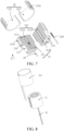
FIG. 7 is an exploded view of a viewing angle from which a heating element in a heating device according to an embodiment of this application is a heating member. -
FIG. 8 is an exploded view of a viewing angle from which a heating element in a heating device according to an embodiment of this application is a metal heating mesh. -
FIG. 9 is an exploded view of a viewing angle from which a heating element in a heating device according to an embodiment of this application is a flexible printed circuit (FPC) heating film. -
FIG. 10 is an exploded view of a viewing angle from which a heating element in a heating device according to an embodiment of this application is a resistive heating element. -
FIG. 11 is an exploded view of a viewing angle from which a heating element in a heating device according to an embodiment of this application is an induction coil. -
FIG. 12 is a cross-sectional view of another viewing angle of a heating device according to an embodiment of this application. -
FIG. 13 is a cross-sectional view of a viewing angle from which a heating element in a heating device according to an embodiment of this application is a heating circuit coating. -
FIG. 14 is a cross-sectional view of a viewing angle of an aerosol generating system according to an embodiment of this application. -
FIG. 15 is a cross-sectional view of a viewing angle of a housing and a sheath of an aerosol generating device according to an embodiment of this application. -
FIG. 16 is an exploded view of a viewing angle of a sheath of an aerosol generating device according to an embodiment of this application. -
FIG. 17 is an enlarged view of a portion A inFIG. 12 . -
FIG. 18 is a schematic diagram of a viewing angle of an end cap of an aerosol generating device according to an embodiment of this application. -
FIG. 19 is a schematic diagram of a viewing angle of a second thermal insulation member of an aerosol generating device according to an embodiment of this application. -
FIG. 20 is an enlarged view of a portion B inFIG. 12 . -
FIG. 21 is a cross-sectional view of a heating device according to Embodiment II of this application. -
FIG. 22 is a cross-sectional view of a heat preservation assembly in a heating device according to Embodiment II of this application. -
FIG. 23 is a cross-sectional view of a heat preservation assembly in another heating device according to Embodiment II of this application. -
FIG. 24 is a cross-sectional view of another heating device according to Embodiment II of this application. - For ease of understanding of this application, this application is described in more detail below with reference to the accompanying drawings and specific embodiments. It should be noted that when an element is described to be "fixed to"/"fixedly connected to"/"mounted to" another element, the element may be directly fixed to the another element, or one or more intermediate elements may exist therebetween. When one element is described to be "connected to" another element, the element may be directly connected to the another element, or one or more intermediate elements may exist therebetween. Terms "vertical", "horizontal", "left", "right", "inner", "outside", and similar expressions used in this specification are for illustrative purposes only.
- Unless otherwise defined, meanings of all technical and scientific terms used in this specification are the same as that usually understood by a person skilled in the technical field to which this application belongs. Terms used in the specification of this application are merely intended to describe objectives of the specific embodiments, but are not intended to limit this application. A term "and/or" used in this specification includes any or all combinations of one or more related listed items.
- In addition, the technical features involved in the different embodiments of this application described below may be combined with each other so long as they do not constitute a conflict with each other.
- In this specification, the "mounting" includes fixing or limiting an element or a device to a specific position or place in a manner such as welding, screwing, snapping, or bonding. The element or the device may keep still at the specific position or place or move within a limited range. The element or the device may or may not be disassembled after being fixed or limited to the specific position or place, which is not limited in the embodiments of this application.
- Referring to
FIG. 1 , aheating device 100 includes aheat preservation assembly 10 and anairflow heating assembly 20. An interior of theheat preservation assembly 10 is provided with a receivingcavity 11 in communication with an outside environment. Theairflow heating assembly 20 is arranged at one end of the receivingcavity 11, and an other end of the receivingcavity 11 is configured to accommodate anaerosol generation article 2000. When theaerosol generation article 2000 is placed in the receivingcavity 11, an air inlet end of theaerosol generation article 2000 is close to theairflow heating assembly 20, and an inner surface of theheat preservation assembly 10 is substantially attached to a circumferential outer surface of theaerosol generation article 2000. The substantial attachment means that a distance L1 between the inner surface of theheat preservation assembly 10 and the circumferential outer surface of theaerosol generation article 2000 placed in the receivingcavity 11 is in a range of 0 mm ≤ L1 ≤ 2 mm. In some embodiments, the distance L1 satisfies 0.2 mm ≤ L1 ≤ 0.7 mm. In some embodiments, the distance L1 is 0.5 mm. Theairflow heating assembly 20 is configured to heat a gas flowing through theairflow heating assembly 20, so that the heated gas heats theaerosol generation article 2000 placed in the receivingcavity 11. In addition, heat of the inner surface of theheat preservation assembly 10 heated by theairflow heating assembly 20 can be directly or indirectly transferred to an outer surface of theaerosol generation article 2000, so as to perform auxiliary heating on theaerosol generation article 2000 and make full use of the heat of theheat preservation assembly 10. - In some embodiments, still referring to
FIG. 1 , theheating device 100 further includes atemperature measurement element 30. Thetemperature measurement element 30 is arranged inside theairflow heating assembly 20. Thetemperature measurement element 30 is configured to measure a temperature of theairflow heating assembly 20, so as to facilitate real-time monitoring and control of the temperature of theairflow heating assembly 20. - For the
heat preservation assembly 10 described above, referring toFIG. 2 , theheat preservation assembly 10 includes aninner tube portion 12 and anouter tube portion 13. Theinner tube portion 12 is provided with a receivingcavity 11. Theouter tube portion 13 is arranged around theinner tube portion 12. Aclosed cavity 14 is jointly defined by theouter tube portion 13 and theinner tube portion 12. An interior of theclosed cavity 14 is in a vacuum state, or filled with an inert gas with low thermal conductivity, so that a temperature of theouter tube portion 13 of theheat preservation assembly 10 is lower than a temperature of theinner tube portion 12, so as to play a role in thermal insulation. It is worth noting that when the interior of theclosed cavity 14 is in the vacuum state, it does not mean that the interior of theclosed cavity 14 is completely vacuum, but it should be understood that an air pressure in theclosed cavity 14 is lower than the standard atmospheric pressure. To be specific, theclosed cavity 14 is in a negative pressure state, and a degree of gas rarefaction in theclosed cavity 14 is measured by a vacuum degree. - It may be understood that in some embodiments, referring to
FIG. 3 , acavity 14 communicating with an outside environment is formed jointly by theouter tube portion 13 and theinner tube portion 12. Thecavity 14 is filled with a medium with low thermal conductivity, for example, thermal insulation materials such as glass fiber, asbestos, rock wool, and silicate. - In some embodiments, referring to
FIG. 4 , theheat preservation assembly 10 may further include an abuttingmember 15. The abuttingmember 15 is arranged on an inner surface of theinner tube portion 12, and the abuttingmember 15 is located between afirst chamber 111 and asecond chamber 112. The abuttingmember 15 is configured to connect to theairflow heating assembly 20 to fix theairflow heating assembly 20 in thefirst chamber 111. In addition, the abuttingmember 15 further has a limiting effect on theairflow heating assembly 20 to prevent theairflow heating assembly 20 from entering thesecond chamber 112 beyond thefirst chamber 111 during mounting. In some embodiments, the abuttingmember 15 may be a convex rib, an engagement tooth, or the like. - In some embodiments, when the
heating device 100 is in a normal operating state, theheat preservation assembly 10 meets at least one of the following conditions: the temperature of theinner tube portion 12 is in a range of 100°C to 150°C, and the temperature of theouter tube portion 13 is in a range of 40°C to 80°C. - In some embodiments, when the
aerosol generation article 2000 is placed in the receivingcavity 11 and theheating device 100 is in normal operation, theinner tube portion 12 meets at least one of the following conditions: the temperature of an end of theinner tube portion 12 close to theaerosol generation article 2000 is in a range of 100°C to 120°C, and the temperature of an end of theinner tube portion 12 close to theairflow heating assembly 20 is in a range of 120°C to 150°C. - For the above receiving
cavity 11, still referring toFIG. 2 , the receivingcavity 11 is provided with afirst chamber 111 and asecond chamber 112, and thefirst chamber 111 and thesecond chamber 112 are in communication with each other along a first direction X. The first direction X is parallel to a center line of theheat preservation assembly 10. Thefirst chamber 111 is configured to allow mounting of theairflow heating assembly 20, and thesecond chamber 112 is configured to allow mounting of theaerosol generation article 2000. When theaerosol generation article 2000 is mounted in thesecond chamber 112, and a user sucks an air outlet end of the aerosol generation article 2000 (the air inlet end and the air outlet end are respectively arranged on two ends of the aerosol generation article 2000), a negative pressure is generated inside the aerosol, and an external gas flows through theairflow heating assembly 20 and is heated by theairflow heating assembly 20, and then enters theaerosol generation article 2000 from the air inlet end to complete heating of theaerosol generation article 2000. - In some embodiments, still referring to
FIG. 2 , a cross-sectional area of thefirst chamber 111 is greater than a cross-sectional area of thesecond chamber 112, so that the receivingcavity 11 is in a shape of a step, which may be beneficial to ensure that an inner wall surface of thesecond chamber 112 is substantially attached to the circumferential outer surface of theaerosol generation article 2000 when an outer contour of theairflow heating assembly 20 along the first direction X is larger than an outer contour of theaerosol generation article 2000 along the first direction X. In addition, it is convenient for theairflow heating assembly 20 to be mounted in thefirst chamber 111. A cross section of thefirst chamber 111 and a cross section of thesecond chamber 112 are both perpendicular to the first direction X. It may be understood that in some embodiments, an inner diameter of the receivingcavity 11 along the first direction X may also be the same. - In the embodiment of this application, the receiving
cavity 11 extends through theinner tube portion 12 along the first direction X, that is, openings at both ends of the receivingcavity 11 in communication with the outside environment are respectively located at both ends of theheat preservation assembly 10. It may be understood that in some other embodiments, referring toFIG. 4 , an arrow represents an airflow direction. Theheat preservation assembly 10 further includes aperipheral plate 16. Theperipheral plate 16 is arranged on an outer side of theouter tube portion 13, so that the openings of the receivingcavity 11 in communication with the outside environment may be both located at the same end of theheat preservation assembly 10. An air inlet channel is formed between theperipheral plate 16 and theouter tube portion 13. A gas absorbs heat from theouter tube portion 13 while flowing through the air inlet channel, so that the gas is preheated before entering theair guide channel 211. - For the above
airflow heating assembly 20, referring toFIG. 6 , theairflow heating assembly 20 includes anair guide element 21 and aheating element 22. Theair guide element 21 is configured to allow gas flow, and theheating element 22 is configured to heat theair guide element 21, or theair guide element 21 spontaneously generates heat under the action of theheating element 22, thereby heating the gas flowing through theair guide element 21. - In the embodiment of this application, the
air guide element 21 is made of graphite, and theair guide element 21 has good thermal conductivity, which is beneficial to improve heating efficiency. In some embodiments, theair guide element 21 is made of a graphite alloy. The graphite alloy has good magnetic conductivity and relatively high thermal conductivity. The good magnetic conductivity causes theheating element 22 to adopt an electromagnetic heating mode in addition to a resistive heating mode, so that theair guide element 21 can also generate heat, which increases an optional heating solution. The relatively high thermal conductivity can effectively reduce time required for theheating element 22 to heat theair guide element 21 to a predetermined temperature, so as to improve heating efficiency of theairflow heating assembly 20. - Referring to
FIG. 7 , theair guide element 21 is provided with asecond mounting groove 212 and at least oneair guide channel 211 extending through the air guide element, and theair guide channel 211 enables an external gas to flow from one end of theair guide element 21 to an other end of theair guide element 21. In the embodiment of this application, theair guide channel 211 extends through theair guide element 21 along the first direction X, and a plurality ofair guide channels 211 are provided. In some other embodiments, a shape of theair guide channel 211 may be an irregular shape. For example, theair guide channel 211 may be inclined, spiral, or winding in shape inside theair guide element 21, as long as the external gas flows through theair guide channel 211 from one end of theair guide element 21 to the other end of theair guide element 21. Thesecond mounting groove 212 is located in the center of a cross section of theair guide element 21. Thesecond mounting groove 212 is configured to allow mounting of thetemperature measurement element 30. The cross section of theair guide element 21 is perpendicular to the first direction X. Thesecond mounting groove 212 is arranged in a central position of the cross section of theair guide element 21, so that temperature data measured by thetemperature measurement element 30 may be closer to a temperature at which air is heated, thereby improving accuracy of temperature control of theairflow heating assembly 20. Certainly, in some embodiments, the second mountinggroove 212 is anair guide channel 211 located in the center of the cross section of theair guide element 21, and thetemperature measurement element 30 is arranged in theair guide channel 211. - The plurality of
air guide channels 211 are in a shape of a cylinder, and a diameter D1 of each of theair guide channels 211 satisfies 0 < D1 ≤ 0.5 mm. By adopting a scheme of small-diameterair guide channels 211, on the one hand, the number ofair guide channels 211 may be increased, and on the other hand, the heating efficiency of the gas flowing through theair guide channels 211 may be improved, to prevent a gas flow from being large and a poor gas heating effect as a result of an excessively large diameter of theair guide channel 211. - A ratio of a sum of the areas of the cross sections of the plurality of
air guide channels 211 to the area of the cross section of theair guide element 21 is greater than or equal to 1/5. The cross section of theair guide channel 211 is within the cross section of theair guide element 21, and the cross sections of theair guide channel 211 and theair guide element 21 are both perpendicular to the center line of theair guide element 21. On the premise of satisfying structural stability of theair guide element 21, when the ratio of the area of the cross section of theair guide channel 211 to the area of the cross section of theair guide element 21 is closer to 1, it indicates a larger effective area of theair guide channel 211 and a larger available gas flow area. When the area of the cross section of a singleair guide channel 211 is fixed, a larger quantity ofair guide channels 211 may be provided on theair guide element 21. - A plurality of
air guide channels 211 are arranged around the center of theair guide element 21, and a ratio of a quantity ofair guide channels 211 located in an inner rim to a quantity ofair guide channels 211 located in an outer rim is equal to a ratio of a radius of the inner rim to a radius of the outer rim. Along a direction that the center of the cross section of theair guide element 21 points to an edge of the cross section of theair guide element 21, a growing quantity ofair guide channels 211 that may be provided leads to an increase in flow channels of gas. In some embodiments, the plurality ofair guide channels 211 are arranged in a circumferential array, that is, a distance between two adjacentair guide channels 211 located in the same rim is equal. - The
air guide element 21 satisfies at least one of the following conditions: (1) a diameter D3 of theair guide element 21 is in a range of 4 mm ≤ D3 ≤ 8 mm; (2) the diameter D3 of theair guide element 21 is in a range of 6 mm ≤ D3 ≤ 7 mm; (3) a cross-sectional area S1 of theair guide element 21 is in a range of 10 mm ≤ S1 ≤ 50 mm2; (4) the cross-sectional area S1 of theair guide element 21 is in a range of 25 mm ≤ S1 ≤ 35 mm2; (5) an axial length L1 of theair guide element 21 is in a range of 5 mm ≤ L1 ≤ 10 mm; and (6) the axial length L1 of theair guide element 21 is in a range of 7 mm ≤ L1 ≤ 9 mm. - In the embodiment of this application, the cross-sectional area of the
air guide element 21 is the same as the cross-sectional area of thesecond chamber 112, so that theair guide element 21 covers the air inlet end of theaerosol generation article 2000 accommodated in thesecond chamber 112 as much as possible, to ensure that the air heated by theair guide element 21 has a larger heating area for theaerosol generation article 2000. Since the cross-sectional area of thefirst chamber 111 is greater than the cross-sectional area of thesecond chamber 112, theheating element 22 may be arranged on a circumferential outer side of theair guide element 21. Certainly, in some embodiments, theheating element 22 may be mounted by reducing part of the outer diameter of theair guide element 21, so that a gap is defined between theair guide element 21 and theheat preservation assembly 10, causing the cross-sectional area of thefirst chamber 111 to be consistent with the cross-sectional area of thesecond chamber 112, which is convenient for processing and manufacturing of theheat preservation assembly 10. - In some embodiments, still referring to
FIG. 7 , theair guide element 21 includes a firstair guide block 213 and a secondair guide block 214. The firstair guide block 213 is provided with afirst groove 2131, and the secondair guide block 214 is provided with asecond groove 2141. When the firstair guide block 213 and the secondair guide block 214 are spliced, thefirst groove 2131 and thesecond groove 2141 jointly define the above second mountinggroove 212. Theair guide element 21 adopts a split design, which may help thetemperature measurement element 30 to be mounted in the second mountinggroove 212 more easily, and improve assembly efficiency of theheating device 100. - In some embodiments, still referring to
FIG. 7 , theair guide element 21 is provided with a first mountinggroove 215. Thefirst mounting groove 215 is configured to allow mounting of theheating element 22. At least one first mountinggroove 215 is provided. When one first mountinggroove 215 is provided, the first mountinggroove 215 is provided in the center of theair guide element 21. Theheating element 22 is arranged in the center of theair guide element 21, so that a characteristic that theheating element 22 transfers heat in bursts may be fully utilized, and heat loss of theheating element 22 may be reduced. When a quantity of first mountinggrooves 215 is two or more, two or more first mountinggrooves 215 are arranged around the center of theair guide element 21. To be specific, the first mountinggrooves 215 are located between the center of theair guide element 21 and the edge of theair guide element 21, and theheating element 22 may be mounted in each of the first mountinggrooves 215. Thefirst mounting groove 215 is provided between the center and the edge of theair guide element 21, so that theheating element 22 can quickly heat theair guide element 21, and a degree of heating between the center and the edge of theair guide element 21 is relatively uniform. Certainly, the first mountinggroove 215 may be provided as a through groove or a blind groove based on an actual situation. - A diameter D2 of the first mounting
groove 215 satisfies the following requirements: 0 mm < D2 ≤ 1.7 mm. On the premise that theheating member 20 can be mounted in the first mountinggroove 215, a smaller diameter of the first mountinggroove 215 leads to a more favorable increase in the quantity ofair guide channels 211. - In some embodiments, still referring to
FIG. 7 , a circumferential outer surface of theair guide element 21 is provided with a first mountingregion 216 and asecond mounting region 217. Thefirst mounting region 216 is configured to connect to the inner surface of theinner tube portion 12 of theheat preservation assembly 10 through interference fit, and theair guide element 21 is fixed to theinner tube portion 12 under the action of friction. In some embodiments, the first mountingregion 216 is provided with afirst protrusion 2161. Thefirst protrusion 2161 abuts against the inner surface of theinner tube portion 12 of theheat preservation assembly 10 to form line contact or point contact. Certainly, in some other embodiments, the first mountingregion 216 may be connected to theinner tube portion 12 in another connection manner, such as bonding. - The
second mounting region 217 does not abut against the inner surface of theinner tube portion 12 of theheat preservation assembly 10. A gap is formed between the second mountingregion 217 and theinner tube portion 12, which may reduce a contact area between theair guide element 21 and theinner tube portion 12, and prevent the heat of theair guide element 21 from being transferred to theinner tube portion 12 of theheat preservation assembly 10 excessively fast. In some embodiments, the second mountingregion 217 may be configured to allow mounting of theheating element 22, and theheating element 22 is sleeved on an outer surface of the second mountingregion 217 to heat theair guide element 21 from outside to inside. Theheating element 22 is arranged in the second mountingregion 217, so that a structural layout among theheating element 22, theair guide element 21, and theheat preservation assembly 10 can be more compact on the premise that theheating element 22 meets a heating function. - For the
above heating element 22, in some embodiments, referring toFIG. 8 andFIG. 9 , theheating element 22 includes ametal heating mesh 221 or a flexible printed circuit (FPC)heating film 222. Themetal heating mesh 221 or theFPC heating film 222 is at least partially arranged around an outer peripheral surface of theair guide element 21, and both themetal heating mesh 221 and theFPC heating film 222 are electrically connected to an external power supply. When the external power supply supplies power to themetal heating mesh 221 or theFPC heating film 222, themetal heating mesh 221 or theFPC heating film 222 can generate heat, thereby heating theair guide element 21. Surfaces of themetal heating mesh 221 and theFPC heating film 222 are both subjected to oxidation treatment or electrical insulation treatment, so that themetal heating mesh 221 or theFPC heating film 222 only conducts heat to the outside but does not conduct electricity. - In some embodiments, referring to
FIG. 10 , theheating element 22 includes aresistive heating element 223, a first insulatinglayer 224, and a second insulatinglayer 225. Theresistive heating element 223 is at least partially arranged on the outer peripheral surface of theair guide element 21, the first insulatinglayer 224 is arranged between theair guide element 21 and theresistive heating element 223, and the second insulatinglayer 225 is arranged between theresistive heating element 223 and the inner surface of theinner tube portion 12 of theheat preservation assembly 10. Theresistive heating element 223 is electrically connected to the external power supply. When the external power supply supplies power to theresistive heating element 223, theresistive heating element 223 can generate heat, thereby heating theair guide element 21. The first insulatinglayer 224 and the second insulatinglayer 225 are both configured to electrically insulate theresistive heating element 223, so as to prevent a situation of electric leakage as a result of the electric energy from the external power supply being conducted to theair guide element 21 or theheat preservation assembly 10, thereby improving safety of theheating device 100. - In some embodiments, the first insulating
layer 224 and the second insulatinglayer 225 are also adhesive to fix theresistive heating element 223 and theair guide element 21 in thefirst chamber 111 of the receivingcavity 11. Specifically, the first insulatinglayer 224 fixes theair guide element 21 to theresistive heating element 223, and the second insulatinglayer 225 fixes theresistive heating element 223 to theinner tube portion 12 of theheat preservation assembly 10. - In some embodiments, referring to
FIG. 11 , theheating element 22 includes aninduction coil 226. Theinduction coil 226 is sleeved on a circumferential outer surface of theair guide element 21, and theinduction coil 226 is electrically connected to an external power supply. When the external power supply supplies power to theinduction coil 226, theinduction coil 226 generates an alternating magnetic field. When theair guide element 21 with good magnetic conductivity is located in the alternating magnetic field, the air guide element can generate heat, thereby heating air flowing through theair guide element 21. - In some embodiments, still referring to
FIG. 11 , theheating element 22 further includes abracket 227. Thebracket 227 is in a shape of a cylinder. Theinduction coil 226 is wound around thebracket 227. Thebracket 227 is sleeved on an outer side of theair guide element 21. Thebracket 227 is configured to support theinduction coil 226 to prevent theinduction coil 226 from being deformed. - In some embodiments, still referring to
FIG. 11 , theheating element 22 further includes a magneticfield shielding layer 228. The magneticfield shielding layer 228 is arranged between theinduction coil 226 and theinner tube portion 12 of theheat preservation assembly 10. The magneticfield shielding layer 228 is configured to shield influence of the alternating magnetic field generated by the energizedinduction coil 226 on theinner tube portion 12, to reduce heat generated in theinner tube portion 12. - In some embodiments, referring to
FIG. 7 , theheating element 22 includes aheating member 229. Theheating member 229 is arranged in the first mountinggroove 215. Theheating member 229 is a columnar body of resistive heating type. Theheating member 229 is electrically connected to an external power supply. When theheating member 229 is arranged in the first mountinggroove 215, theheating member 229 transfers heat outward in bursts. Compared with the heating mode from outside to inside, theheating member 229 has less energy consumption loss and a high heat utilization rate. - In some embodiments, the
heating member 229 is spirally formed by a resistive heating wire, or theheating member 229 is cylindrical with a vent air gap, and a hollow state of theheating member 229 may facilitate flow of the gas in the first mountinggroove 215 and increase the contact area between the air and theair guide element 21. - The
heating member 229 satisfies at least one of the following conditions: (1) a diameter D4 of theheating member 229 satisfies 1 mm ≤ D4 ≤ 2 mm; (2) the diameter D4 of theheating member 229 satisfies 1.4 mm ≤ D4 ≤ 1.7 mm; (3) an area S2 defined by an outer contour of a cross section of theheating member 229 is in a range of 0.7 mm ≤ S2 ≤ 3.5 mm2, where the cross section of theair guide element 21 is perpendicular to the center line of theair guide element 21; and (4) an axial length L2 of theheating member 229 is in a range of 4 mm ≤ L2 ≤ 9 mm. - It is worth noting that in some embodiments, when the first mounting
groove 215 provided with theheating member 229 and the second mountinggroove 212 provided with thetemperature measurement element 30 are both located in the center of theair guide element 21, the first mountinggroove 215 and the second mountinggroove 212 are the same mounting groove. Theheating member 229 and thetemperature measurement element 30 are both located in the mounting groove. In this case, thetemperature measurement element 30 performs temperature measurement by using a temperature coefficient of resistance (TCR). Certainly, in some other embodiments, thetemperature measurement element 30 may further perform temperature measurement by using a negative temperature coefficient (NTC), a thermistor, and a thermocouple. - In some embodiments, referring to
FIG. 12 andFIG. 13 , theheating element 22 is aheating circuit coating 230. Theheating circuit coating 230 is applied onto an inner wall surface of theinner tube portion 12, and theheating circuit coating 230 is electrically connected to an external power supply through a wire. When theair guide element 21 is mounted to thefirst chamber 111, the outer peripheral surface of theair guide element 21 at least partially abuts against theheating circuit coating 230. Theheating circuit coating 230 is configured to heat theair guide element 21. Theheating circuit coating 230 has characteristics of a thin coating and high heating efficiency, which may reduce a volume of theairflow heating assembly 20. In addition, theheating circuit coating 230 is directly applied onto the inner surface of theinner tube portion 12 and integrated with theheat preservation assembly 10, so that a quantity of parts may be reduced, and the mounting is more convenient. - It is worth noting that, in order to save power consumption of the
heating element 22, in the embodiment of this application, only the aboveheating circuit coating 230 is applied onto the inner wall surface of thefirst chamber 111, and the aboveheating circuit coating 230 is not applied onto the inner wall surface of thesecond chamber 112. Due to the high thermal conductivity of theair guide element 21, theheating circuit coating 230 applied onto the inner wall surface of thefirst chamber 111 may lead to a relatively high thermal conductivity, less heat loss, and short heating time. However, if theheating circuit coating 230 is arranged on the inner wall surface of thesecond chamber 112, the thermal conductivity of the circumferential outer surface of the aerosol generation article is relatively low, and the heat loss of theheating element 22 is relatively high, which helps to heat the aerosol generation article, but increases the power consumption of theheating element 22. - In some embodiments, referring to
FIG. 7 , theairflow heating assembly 20 further includes a firstthermal insulation member 23. The firstthermal insulation member 23 is arranged in the first mountingregion 216. When theair guide element 21 with the firstthermal insulation member 23 sleeved thereon is mounted to theinner tube portion 12 of theheat preservation assembly 10, an inner side and an outer side of the firstthermal insulation member 23 respectively abut against an inner surface of theair guide element 21 and the inner surface of theinner tube portion 12. Theair guide element 21 is fixed to theinner tube portion 12 under the action of friction between the firstthermal insulation member 23 and theinner tube portion 12. - In the embodiment of this application, the first
thermal insulation member 23 is made of ZrO2 (zirconium dioxide) and a compound thereof, and the firstthermal insulation member 23 has at least characteristics of high temperature resistance, low thermal conductivity, and corrosion resistance. In some other embodiments, the firstthermal insulation member 23 may also be made of a thermal insulation material such as metal and/or non-metal and a compound thereof. - When only the first mounting
region 216 is provided with thefirst protrusion 2161, the first mountingregion 216 of theair guide element 21 abuts against the inner surface of the firstthermal insulation member 23 to form line contact or point contact, thereby reducing the contact area. In this case, heat transferred directly from theair guide element 21 to the firstthermal insulation member 23 is less than heat transferred when the first mountingregion 216 directly contacts the inner surface of the firstthermal insulation member 23, which may effectively reduce the heat loss of theair guide element 21 and improve thermal efficiency. - In some embodiments, an outer surface of the first
thermal insulation member 23 may also be provided with afirst protrusion 2161, so that when the outer surface of the firstthermal insulation member 23 abuts against the inner surface of theinner tube portion 12, the line contact or the point contact is formed, thereby reducing the contact area. Compared with the solution of only providing thefirst protrusion 2161 in the first mountingregion 216, the solution of providing thefirst protrusion 2161 on the outer surface of the firstthermal insulation member 23 further reduces the heat loss of theair guide element 21. Certainly, the solution of only providing thefirst protrusion 2161 on the outer surface of the firstthermal insulation member 23 is also within the protection scope of this application. In some embodiments, thefirst protrusion 2161 may be directly arranged on the inner surface and the outer surface of the firstthermal insulation member 23 to facilitate manufacturing of the firstthermal insulation member 23. - In the embodiment of this application, the first
thermal insulation member 23 includes afirst split member 231 and asecond split member 232. Thefirst split member 231 covers part of the first mountingregion 216, and thesecond split member 232 covers part of the first mountingregion 216. Thefirst split member 231 and thesecond split member 232 are spliced to form a cavity for allowing mounting of theair guide element 21. Certainly, thefirst split member 231 and thesecond split member 232 may not completely cover the first mountingregion 216 after being spliced, and may partially cover the first mountingregion 216. A main purpose of arranging thefirst split member 231 and thesecond split member 232 is to facilitate the mounting and removal of the firstthermal insulation member 23 and theair guide element 21. It is worth noting that in some other embodiments, the firstthermal insulation member 23 may be divided into three or more separate members. - In order to help readers more easily understand the technical effects brought about by the technical solutions of the embodiments of this application, the operating principle of the
heating device 100 is briefly described below. - When the
aerosol generation article 2000 is accommodated in the receivingcavity 11 of theheat preservation assembly 10, part of the circumferential outer surface of theaerosol generation article 2000 is substantially attached to the inner surface of theinner tube portion 12. When the external power supply supplies power to theheating element 22, theheating element 22 heats theair guide element 21 or theair guide element 21 generates heat by self-heating under the action of theheating element 22, air flowing through a conductor channel of theair guide element 21 is heated, and the heated air enters the interior of theaerosol generation article 2000 from the air inlet end of theaerosol generation article 2000 for heating. In addition, theinner tube portion 12 of theheat preservation assembly 10 is heated by the heating assembly and has a certain amount of heat. Since part of the circumferential outer surface of theaerosol generation article 2000 is substantially attached to the inner surface of theinner tube portion 12, the heat of theinner tube portion 12 can be transferred to part of the circumferential outer surface of theaerosol generation article 2000, to perform auxiliary heating on theaerosol generation article 2000, so that theaerosol generation article 2000 is heated more evenly. - The
heating device 100 in the embodiments of this application includes aheat preservation assembly 10 and anairflow heating assembly 20. Theheat preservation assembly 10 is internally provided with a receivingcavity 11. The receivingcavity 11 is configured to accommodate anaerosol generation article 2000. Theairflow heating assembly 20 is arranged in the receivingcavity 11. Theairflow heating assembly 20 is configured to heat a gas flowing through theairflow heating assembly 20, so that the heated gas heats theaerosol generation article 2000 placed in the receivingcavity 11. When theaerosol generation article 2000 is placed in the receivingcavity 11, an inner surface of theheat preservation assembly 10 is substantially attached to a circumferential outer surface of theaerosol generation article 2000, and heat of an inner wall surface of theheat preservation assembly 10 can be transferred to the circumferential outer surface of theaerosol generation article 2000 for auxiliary heating, so that the heat of theheat preservation assembly 10 is effectively used to heat an axial outer surface of theaerosol generation article 2000, and parts and components of theheating device 100 are reduced. - Based on the same inventive concept, referring to
FIG. 14 , this application further provides anaerosol generating device 1000, including ahousing 200, acircuit device 300, asheath 400, and theabove heating device 100. Thesheath 400 is sleeved on an outer side of theheating device 100, and thesheath 400 is configured to accommodate and support theheating device 100. Thecircuit device 300, thesheath 400, and theheating device 100 are all accommodated in thehousing 200, and thecircuit device 300 is electrically connected to theheating device 100. Thecircuit device 300 is configured to provide electric energy for theheating device 100, so that theheating device 100 can heat theaerosol generation article 2000. Thehousing 200 is configured to accommodate and fix thecircuit device 300 and thesheath 400. - For the
above housing 200, referring toFIG. 15 , thehousing 200 is provided with a receivingspace 201, afirst socket 202, a separatingplate 203, and a fourth throughhole 204. The separatingplate 203 is arranged in the receivingspace 201, and the separatingplate 203 separates the receivingspace 201 into a firstaccommodating cavity 2011 and a secondaccommodating cavity 2012 arranged in a top-to-bottom direction. The firstaccommodating cavity 2011 is configured to accommodate thesheath 400, theheating device 100, and part of thecircuit device 300. The secondaccommodating cavity 2012 is configured to accommodate part of thecircuit device 300. Thefirst socket 202 is arranged on a side wall of thehousing 200, and thefirst socket 202 brings the firstaccommodating cavity 2011 into communication with an outside environment. In addition, thefirst socket 202 is in communication with the receivingcavity 11 of theheat preservation assembly 10 in theheating device 100. Thefirst socket 202 is configured to allow insertion or removal of the externalaerosol generation article 2000 into or from the receivingcavity 11 of theheat preservation assembly 10 in theheating device 100. In some embodiments, the firstaccommodating cavity 2011 and the secondaccommodating cavity 2012 are sealed to improve airtightness of the secondaccommodating cavity 2012 and reduce a possibility that operating performance of thecircuit device 300 accommodated in the secondaccommodating cavity 2012 is affected by the outside environment or the gas in theheating device 100. The fourth throughhole 204 is provided on the side wall of thehousing 200. The fourth throughhole 204 brings the firstaccommodating cavity 2011 into communication with the outside environment. The fourth throughhole 204 is configured for exposure of part of thecircuit device 300, so that the external power supply can be electrically connected to thecircuit device 300. The fourth throughhole 204 is further configured to allow an external gas to enter the firstaccommodating cavity 2011, so as to enter theheating device 100 to be heated. - For the foregoing
circuit device 300, referring toFIG. 14 andFIG. 15 , thecircuit device 300 includes a printed circuit board (PCB)circuit board 301, abattery module 302, and a charginginterface 303. ThePCB circuit board 301 and the charginginterface 303 are both arranged in the firstaccommodating cavity 2011, and the charginginterface 303 is exposed at the fourth throughhole 204. Thebattery module 302 is disposed in the secondaccommodating cavity 2012. ThePCB circuit board 301 is electrically connected to theheating element 22, thetemperature measurement element 30, the battery module PCB circuit board302, and the charginginterface 303 in theheating device 100. ThePCB circuit board 301 is configured to perform parameter control and data acquisition on theheating element 22 and thetemperature measurement element 30. Thebattery module 302 is configured to supply electric energy to theheating element 22 and thetemperature measurement element 30, and the charginginterface 303 is configured for insertion of an external power connector to realize charging of thebattery module 302 or directly supply electric energy to theheating element 22 and thetemperature measurement element 30 by using the external power supply. - In some embodiments, the charging
interface 303 may not be provided, and thebattery module 302 may use a detachable lithium battery, or the like. In some embodiments, two or morePCB circuit boards 301 are arranged. The two or morePCB circuit boards 301 are stacked in parallel in the firstaccommodating cavity 2011, and thePCB circuit boards 301 and thesheath 400 are arranged in the firstaccommodating cavity 2011 in a left-to-right direction, so that a layout of thePCB circuit boards 301 and thesheath 400 is more reasonable. - In some embodiments, sealing treatment may be performed between the first
accommodating cavity 2011 and the secondaccommodating cavity 2012 based on actual requirements, to prevent a gas generated by theair guide element 21 in the firstaccommodating cavity 2011 heating theaerosol generation article 2000 from entering the secondaccommodating cavity 2012 and affecting the operating performance of thebattery module 302. - For the
above sheath 400, referring toFIG. 14 to FIG. 16 , thesheath 400 includes anupper shell 402 and alower shell 403. Theupper shell 402 and thelower shell 403 jointly define a first mountingcavity 401. The first mountingcavity 401 is configured to accommodate theheating device 100 and allow insertion of anaerosol generation article 2000. An end of theupper shell 402 facing away from thelower shell 403 is further provided with asecond socket 4021. Thesecond socket 4021 brings the first mountingcavity 401 into communication with the outside environment. Thesecond socket 4021 is in direct communication with thefirst socket 202, so that the externalaerosol generation article 2000 can enter the first mountingcavity 401 through thefirst socket 202 and thesecond socket 4021, and then enter the receivingcavity 11 of theheat preservation assembly 10 in theheating device 100. - An inner surface of the first mounting
cavity 401 is provided with a firstconvex rib 4011, astep surface 4012, and a secondconvex rib 4013. At least one firstconvex rib 4011 is arranged. The at least one firstconvex rib 4011 extends from thesecond socket 4021 toward a cavity bottom of the first mountingcavity 401. The firstconvex rib 4011 is configured to abut against the outer surface of theaerosol generation article 2000 inserted into the first mountingcavity 401. The firstconvex rib 4011 supports theaerosol generation article 2000 relative to the inner surface of the first mountingcavity 401 to form an air guide groove. The air guide groove is configured to allow an external gas to enter the first mountingcavity 401. The firstconvex rib 4011 is further configured to abut against the outer surface of theouter tube portion 13 of theheat preservation assembly 10. The firstconvex rib 4011 supports theheat preservation assembly 10 relative to the inner surface of the first mountingcavity 401 to form the air guide groove, so that the external gas can smoothly enter the cavity bottom of the first mountingcavity 401. - The
step surface 4012 is arranged on the inner surface of the first mountingcavity 401. Thestep surface 4012 is configured to abut against one end of theheat preservation assembly 10 in theheating device 100. Thestep surface 4012 and the cavity bottom of the first mountingcavity 401 jointly fix theheat preservation assembly 10 in the first mountingcavity 401. Certainly, an air guide groove is still formed at a position where one end of theheat preservation assembly 10 abuts against thestep surface 4012. The secondconvex rib 4013 is arranged at the cavity bottom of the first mountingcavity 401, and the secondconvex rib 4013 supports an other end of theheat preservation assembly 10 relative to the cavity bottom to form an air guide groove, so that the gas entering the cavity bottom of the first mountingcavity 401 can enter theair guide element 21 to be heated. - The
lower shell 403 is provided with asecond mounting cavity 4031 and a first throughhole 4032. Thesecond mounting cavity 4031 is provided on an outer side of thelower shell 403, and the first throughhole 4032 extends through a side wall of thelower shell 403 to extend through the first mountingcavity 401 and the second mountingcavity 4031. Thesecond mounting cavity 4031 is configured to accommodate thePCB circuit board 301. The first throughhole 4032 is configured to allow a cable connecting thePCB circuit board 301 to theheating element 22 and thetemperature measurement element 30 in theheating device 100 to pass through, and/or for the external gas to enter the second mountingcavity 4031 from the fourth throughhole 204 and then enter the cavity bottom of the first mountingcavity 401 from the second mountingcavity 4031 to be heated in theair guide element 21. - In some embodiments, the
upper shell 402 and thelower shell 403 may be integrally formed. - In some embodiments, referring to
FIG. 17 and FIG. 18 , theaerosol generating device 1000 further includes anend cap 500. Theend cap 500 is arranged at the cavity bottom of the first mountingcavity 401. Two ends of theend cap 500 respectively abut against theair guide element 21 of theheating device 100 and the secondconvex rib 4013. Theend cap 500 is made of a material with low thermal conductivity, and theend cap 500 is configured to prevent theair guide element 21 from directly contacting the cavity bottom of the first mountingcavity 401 and transferring heat to thelower shell 403 excessively fast. Theend cap 500 is provided with a second throughhole 501 and a thirdconvex rib 502. The second throughhole 501 is configured to allow the gas at the cavity bottom of the cavity to flow to theair guide element 21 and allowing the cable connecting thePCB circuit board 301 to theheating element 22 and thetemperature measurement element 30 in theheating device 100 to pass through. - In some embodiments, referring to
FIG. 17 andFIG. 19 , theaerosol generating device 1000 further includes a secondthermal insulation member 600. The secondthermal insulation member 600 is arranged on a side of theend cap 500 facing theheating device 100, that is, the secondthermal insulation member 600 is located between theair guide element 21 and theend cap 500. The secondthermal insulation member 600 is made of a material with low thermal conductivity. The secondthermal insulation member 600 is configured to reduce heat transferred from theair guide element 21 to theend cap 500. The secondthermal insulation member 600 is provided with a third throughhole 601 and a fourthconvex rib 602. The third throughhole 601 is configured to allow a gas to flow and for allowing the cable connecting thePCB circuit board 301 to theheating element 22 and thetemperature measurement element 30 in theheating device 100 to pass through. The thirdconvex rib 502 forms point contact with the secondthermal insulation member 600, and the fourthconvex rib 602 is arranged at an end of the secondthermal insulation member 600 close to theair guide element 21. The fourthconvex rib 602 is configured to form point contact with theair guide element 21. - In the embodiment of this application, the second
thermal insulation member 600 and theend cap 500 are arranged between theair guide element 21 and the cavity bottom of the first mountingcavity 401 for double thermal insulation, and the secondthermal insulation member 600 is connected to theair guide element 21 and theend cap 500, and theend cap 500 is connected to the cavity bottom both in a manner of point contact, thereby effectively reducing the heat directly transferred by theair guide element 21 to thelower shell 403. On the one hand, thesheath 400 can operate in a relatively low temperature environment, thereby effectively prolonging a service life of thesheath 400. On the other hand, the heat loss of theair guide element 21 can be effectively reduced, and the thermal efficiency of theair guide element 21 is improved. It may be understood that, in some embodiments, the secondthermal insulation member 600 and theend cap 500 may be integrally formed. - In the embodiment of this application, the second
thermal insulation member 600 and theend cap 500 are made of ZrO2 (zirconium dioxide) and a compound thereof, and the secondthermal insulation member 600 and theend cap 500 have at least characteristics of high temperature resistance, low thermal conductivity, and corrosion resistance. In some other embodiments, the secondthermal insulation member 600 and/or theend cap 500 may also be made of a thermal insulation material such as metal and/or non-metal and a compound thereof, to reduce production costs. - Based on the same inventive concept, this application further provides an embodiment of an
aerosol generating system 10000. Referring toFIG. 14 andFIG. 20 , theaerosol generating system 10000 includes anaerosol generation article 2000 and the aboveaerosol generating device 1000. Theaerosol generating device 1000 is configured for insertion of theaerosol generation article 2000, and theaerosol generating device 1000 heats theaerosol generation article 2000 to generate smoke for a user to inhale. Theaerosol generation article 2000 includes at least atobacco section 2001, acooling section 2002, and amouthpiece section 2003. Thetobacco section 2001, thecooling section 2002, and themouthpiece section 2003 are connected in sequence, and when theaerosol generation article 2000 is inserted into the receivingcavity 11 of theheat preservation assembly 10, an axial length L2 of thetobacco section 2001 is equal to or slightly greater than a length L3 of thetobacco section 2001 inserted into the receivingcavity 11, to ensure that thecooling section 2002 is not heated by theinner tube portion 12 of theheat preservation assembly 10, thereby affecting cooling performance of thecooling section 2002. The axial length L2 of thetobacco section 2001 being slightly greater than the length L3 of thetobacco section 2001 inserted into the receivingcavity 11 means that a difference between the axial length L2 of thetobacco segment 2001 and the length L3 of thetobacco section 2001 inserted into the receivingcavity 11 is in a range of 0.5 mm ≤ L2-L3 ≤ 2 mm. It may be understood that theaerosol generation article 2000 may further include another section, for example, a filter section, an essential oil section, a filter tip section, or the like. - Mainly referring to
FIG. 21 , aheating device 100a includes atubular body 10a, anairflow channel 30a, and anairflow heating assembly 20a. Thetubular body 10a has a containing cavity inside. The containing cavity is configured to receive at least part of anaerosol generation article 2000. Theairflow channel 30a is in fluid communication with the containing cavity, and air enters the containing cavity through the airflow channel. - In an example, as shown in
FIG. 21 , the air enters the containing cavity from a distal end of the containing cavity. It may be understood that in another example, the air may further enter the containing cavity from a middle region of the containing cavity. - In an example, at least part of the
airflow channel 30a is located inside thetubular body 10a, and theairflow heating assembly 20a is arranged in theairflow channel 30a. The air flowing through theairflow channel 30a flows through theairflow heating assembly 20a, so that theairflow heating assembly 20a can heat the air flowing through theairflow channel 30a. In another example, the airflow channel is located outside the tubular body, at least part of the airflow channel may be defined by an air channel tube, the airflow heating assembly may be located in the airflow channel, or the airflow heating assembly may be arranged around the air channel tube. - The
airflow heating assembly 20a is configured to heat the air flowing through theairflow channel 30a into hot air, and the hot air may flow into an interior of theaerosol generation article 2000 from a distal end of theaerosol generation article 2000 to heat a tobacco section in theaerosol generation article 2000 to generate an aerosol. Certainly, it is not excluded that in another embodiment, the hot air may flow into the interior of theaerosol generation article 2000 from a side wall of theaerosol generation article 2000. - An end of the
tubular body 10a is provided with a first opening 111a, and at least part of theaerosol generation article 2000 is inserted into the containing cavity for accommodation through the first opening 111a. The end with the first opening in the tubular body is defined as a proximal end m1 of the heating device, and a distal end m2 of the heating device is arranged opposite to the proximal end m1. It may be understood that for other parts and components such as the airflow heating assembly and the proximal end m1 and the distal end m2 of the airflow channel, reference may also be made to the above definition. - For the above
tubular body 10a, the containing cavity therein includes a first containingcavity 114a and a second containingcavity 115a. Along a flow direction of the air in the containing cavity, the first containingcavity 114a is located downstream of the second containingcavity 115a. With a proximal end of thetubular body 10a as a reference point, the second containingcavity 115a is provided adjacent to a distal end of the first containingcavity 114a. The first containingcavity 114a and the second containingcavity 115a are both configured to contain a portion of theaerosol generation article 2000. An inner containing diameter of the second containingcavity 115a is greater than a containing radius of the first containingcavity 114a. Since the second containingcavity 115a is located upstream of the first containingcavity 114a, the hot air flows through theaerosol generation article 2000 located in the second containingcavity 115a and then flows into theaerosol generation article 2000 located in the first containingcavity 114a, so that a temperature of a wall defining the second containingcavity 115a in thetubular body 10a is higher than a temperature of a wall defining the first containingcavity 114a in thetubular body 10a. - In an example, the tubular body is not an integrally formed tube, and the wall defining the first containing cavity and the wall defining the second containing cavity in the tubular body are connected by assembly. In an example, the wall defining the first containing cavity and the wall defining the second containing cavity in the tubular body are made of different materials.
- In the embodiments shown in
FIG. 21 and FIG. 22 , thetubular body 10a includes a firsttubular body 11a. - In an example, the first
tubular body 11a contains a thermal insulation material, so that the firsttubular body 11a has a thermal insulation function. The thermal insulation material means that a thermal conductivity of a material is less than 100 W/m.K, preferably less than 40 W/m.K or less than 10 W/m.K at 23°C and a relative humidity of 50%. For example, the thermal insulation material may be made of at least one of a PAEK-based material, a PI material, or a PBI material. The PAEK-based material includes a material such as glass fiber, glass felt, ceramics, silica, alumina, PEEK, PEKK, PEKEKK, or PEK. The PAEK-based material includes a material such as PEEK, PEKK, PEKEKK, or PEK. - In an example, the first
tubular body 11a includes a thermal insulation material surrounding a periphery of the firsttubular body 11a. - In an example, mainly referring to
FIG. 21 and FIG. 22 , thetubular body 10a further includes a secondtubular body 12a. The secondtubular body 12a is arranged on a periphery of the firsttubular body 11a, and acavity 13a is formed between the firsttubular body 11a and the secondtubular body 12a. The firsttubular body 11a is configured to receive and fix at least part of the aerosol generation article, and thecavity 13a is configured to reduce heat transferred from the firsttubular body 11a to the secondtubular body 12a. Thecavity 13a may form a negative pressure thermal insulation layer or a gas thermal insulation layer, that is, an interior of thecavity 13a is in a vacuum negative pressure state or filled with a gas. In other words, an air pressure in thecavity 13a may be less than or equal to an outside atmospheric pressure, or may be less than or equal to a standard atmospheric pressure. The gas filled in thecavity 13a may be a certain gas, which may be for example pure carbon dioxide, pure nitrogen, or pure argon. The gas filled in thecavity 13a may be a mixed gas composed of a plurality of gases. The gas filled in thecavity 13a may be air. Certainly, in another embodiment, thecavity 13a may further be filled with a thermal insulation material. In this example, the firsttubular body 11a may include metal. - The first
tubular body 11a includes afirst portion 112a and asecond portion 113a. Thefirst portion 112a defines a first containingcavity 114a, and thefirst portion 112a is further provided with a first opening 111a. The first opening 111a brings the first containingcavity 114a into communication with an outside environment. Thesecond portion 113a defines a second containingcavity 115a, and the first containingcavity 114a and the second containingcavity 115a are in air communication. The aerosol generation article is inserted into the first containingcavity 114a and the second containingcavity 115a through the first opening 111a. Since the second containingcavity 115a is located upstream of the first containingcavity 114a based on the flow direction of the hot air, a temperature of thesecond portion 113a may be higher than a temperature of thefirst portion 112a. An inner diameter of thesecond portion 113a is greater than an inner diameter of thefirst portion 112a, so that a gap is defined between an outer peripheral surface of theaerosol generation article 2000 and thesecond portion 113a. Thesecond portion 113a is prevented from transferring heat to theaerosol generation article 2000 through the gap, which helps increase thermal resistance between thesecond portion 113a and theaerosol generation article 2000, and prevents theaerosol generation article 2000 contained in the second containingcavity 115a from being carbonized or burned due to overheating. Thefirst portion 112a may be attached to the outer peripheral surface of theaerosol generation article 2000 to clamp theaerosol generation article 2000, thereby helping to keep theaerosol generation article 2000 inside thetubular body 10a. - In addition, the gap between the aerosol generation article and the
second portion 113a may be filled with the hot air entering the second containingcavity 115a, which is helpful to make theaerosol generation article 2000 located in the second containingcavity 115a heated more evenly and improve quality of the generated aerosol. - In an embodiment, the
tubular body 10a or the firsttubular body 11a includes a heating portion. The heating portion may be an electric heating portion. For example, the heating portion includes a resistive material. The resistive material can generate Joule heat when energized, or for example, the heating portion includes an infrared coating. The infrared coating can radiate infrared rays to the containing cavity when energized. The heating portion enables thetubular body 10a or the firsttubular body 11a to generate heat, so that thetubular body 10a or the firsttubular body 11a can cooperate with theairflow heating assembly 20a to jointly heat theaerosol generation article 2000 contained in the containing cavity. Under the action of hot air, a temperature of the second containingcavity 115a is higher than a temperature of the first containingcavity 114a. Therefore, to prevent theaerosol generation article 2000 located in the second containingcavity 115a from being overheated, the inner containing diameter of the second containingcavity 115a is designed to be greater than the inner containing diameter of the first containingcavity 114a, which may prevent theaerosol generation article 2000 from contacting with a cavity wall of the second containingcavity 115a and prevent local overheating of theaerosol generation article 2000. - Mainly referring to
FIG. 22 , along a length direction of thetubular body 10a, an extension length L4 of the second containingcavity 115a satisfies 2 mm ≤ L4 ≤ 3 mm. For example, the extension length L4 of the second containingcavity 115a may be 2.3 mm, 2.5 mm, 2.8 mm, or the like. A difference between an inner diameter D2 of thesecond portion 113a and an inner diameter D1 of thefirst portion 112a satisfies 0.6 mm ≤ D2-D1 ≤ 1 mm. - In some embodiments, mainly referring to
FIG. 22 andFIG. 23 , thefirst portion 112a and thesecond portion 113a have the same outer diameter. To be specific, the firsttubular body 11a has different wall thicknesses at thefirst portion 112a and thesecond portion 113a. Thesecond portion 113a having a smaller wall thickness than thefirst portion 112a may be formed by forming a groove on an inner wall of the firsttubular body 11a. - In another embodiment, the
first portion 112a and thesecond portion 113a have the same wall thickness, and a part of the firsttubular body 11a may be formed by using a shaping process, to form asecond portion 113a that arches outward relative to thefirst portion 112a along a radial direction of the firsttubular body 11a, or form afirst portion 112a that tightens inward relative to thesecond portion 113a along the radial direction of the firsttubular body 11a. In this example, the firsttubular body 11a may be made of metal, so that it is convenient to perform stamping processing on the firsttubular body 11a, for example, stamping outward to form the outwardly archedsecond portion 113a, or stamping inward to form the inwardly tightenedfirst portion 112a. - It should be noted that the first
tubular body 11a and the secondtubular body 12a may further be formed by using another suitable process such as injection molding or casting. - It should be noted that the second
tubular body 12a may also be made of metal, so that a proximal end of the firsttubular body 11a and a proximal end of the secondtubular body 12a may be connected by welding, and a distal end of the firsttubular body 11a and a distal end of the secondtubular body 12a may also be connected by welding, which helps to form a sealedcavity 13a between the firsttubular body 11a and the secondtubular body 12a. - In some embodiments, mainly referring to
FIG. 21 and FIG. 22 , an inner wall surface of thetubular body 10a is further provided with asecond protrusion 14a. Thesecond protrusion 14a is located between theairflow heating assembly 20a and the second containingcavity 115a, and a proximal end of theairflow heating assembly 20a abuts against thesecond protrusion 14a, so as to fixedly mount theairflow heating assembly 20a inside thetubular body 10a. A minimum inner diameter of thesecond protrusion 14a is greater than or equal to the inner containing diameter of the first containingcavity 114a. Since thesecond protrusion 14a may be a continuous annularsecond protrusion 14a or may be bumps annularly arranged at intervals, it is only necessary that the minimum inner diameter of thesecond protrusion 14a is greater than or equal to the inner containing diameter of the first containingcavity 114a. When the minimum inner diameter of thesecond protrusion 14a is equal to the inner containing diameter of the first containingcavity 114a, thesecond protrusion 14a forms line contact with an outer peripheral surface of an end portion of the aerosol generation article. Compared with surface contact, the line contact design may effectively reduce heat transferred directly from thesecond protrusion 14a to the end portion of the aerosol generation article. When the minimum inner diameter of thesecond protrusion 14a is greater than the inner containing diameter of the first containingcavity 114a, thesecond protrusion 14a does not come into contact with the end portion of the aerosol generation article, so that the heat directly transferred from thesecond protrusion 14a to the end portion of the aerosol generation article may be further reduced. - For the above
airflow heating assembly 20a, mainly referring toFIG. 21 , theairflow heating assembly 20a includes a thirdthermal insulation member 21a and anairflow heating member 22a. The thirdthermal insulation member 21a is arranged at a proximal end of theairflow heating member 22a, and a proximal end of the thirdthermal insulation member 21a abuts against thesecond protrusion 14a. Theairflow heating member 22a is configured to heat air in theairflow channel 30a to form hot air, and the thirdthermal insulation member 21a is configured to reduce heat directly transferred from theairflow heating member 22a to thetubular body 10a. - In some embodiments, mainly referring to
FIG. 24 , to better support the end portion of the aerosol generation article so that the end portion of the aerosol generation article is located in the second containingcavity 115a, the proximal end of the thirdthermal insulation member 21a is further provided with asupport portion 211a. One ormore support portions 211a may be arranged. A plurality ofsupport portions 211a are arranged at intervals, so that hot air can flow to the end portion of the aerosol generation article through a gap between thesupport portions 211a for heating. It may be understood that the thirdthermal insulation member 21a may be made of a thermal insulation material. For example, the thirdthermal insulation member 21a may be made of ceramics. - The
heating device 100a of this application includes atubular body 10a, anairflow channel 30a, and anairflow heating assembly 20a. A proximal end of thetubular body 10a is provided with a first opening 111a for allowing insertion of theaerosol generation article 2000 therein. A first containingcavity 114a and a second containingcavity 115a for containing part of theaerosol generation article 2000 are successively defined in thetubular body 10a from near to far. An inner containing diameter of the second containingcavity 115a is greater than an inner containing diameter of the first containingcavity 114a. Theairflow channel 30a is configured to allow air to enter the second containingcavity 115a, and theairflow heating assembly 20a is configured to heat the air in theairflow channel 30a. Through structure arrangement with the inner containing diameter of the second containingcavity 115a being greater than the inner containing diameter of the first containingcavity 114a, the end portion of theaerosol generation article 2000 inserted into the second containingcavity 115a may be caused not to directly contact thetubular body 10a, and the end portion of theaerosol generation article 2000 is directly heated through hot air, so that an effect of more uniform heating is achieved, to avoid a situation that the end portion of theaerosol generation article 2000 generates smoke as a result of burning due to local overheating, thereby effectively improving the quality of the generated aerosol. - This application further provides an embodiment of an aerosol generating device. The aerosol generating device includes the
above heating device 100a, and further includes a power supply assembly. For a specific structure and functions of theheating device 100a, reference may be made to the above embodiments, and details are not described herein again. The power supply assembly may include any power supply that can provide electric energy for heat generation of theheating device 100a. The power supply may be any suitable battery. The power supply assembly may further include a control panel. The power supply may be electrically connected to theheating device 100a through the control panel. The control panel may control an operation of the aerosol generating device, including but not limited to controlling a heating power, a heating current, a heating voltage, or the like of theheating device 100a. - Finally, it should be noted that the above embodiments are only used to illustrate the technical solutions of this application, rather than to limit this application. Under the idea of this application, the technical features of the above embodiments or different embodiments may also be combined, the steps may be implemented in any order, and many other variations of different aspects of this application as described above exist, which are not provided in detail for the sake of simplicity. Although this application has been described in detail with reference to the foregoing embodiments, it should be understood by a person skilled in the art that modifications may still be made to the technical solutions described in the foregoing embodiments, or equivalent substitutions may be made to some of the technical features. However, these modifications or substitutions do not make the essence of the corresponding technical solutions depart from the scope of the technical solutions of various embodiments of this application.
Claims (50)
- A heating device for heating an aerosol generation article, the heating device comprising:a heat preservation assembly, comprising an inner tube portion and an outer tube portion, wherein the inner tube portion is internally provided with a receiving cavity, the outer tube portion is arranged around the inner tube portion, a cavity is jointly defined by the outer tube portion and the inner tube portion, and the receiving cavity is configured to accommodate the aerosol generation article; andan airflow heating assembly, arranged in the receiving cavity, wherein the airflow heating assembly is configured to heat a gas flowing through the airflow heating assembly, so that the heated gas heats the aerosol generation article placed in the receiving cavity.
- The heating device according to claim 1, wherein
an interior of the cavity is vacuum or filled with a medium with low thermal conductivity. - The heating device according to claim 1, wherein
the airflow heating assembly comprises an air guide element and a heating element, the air guide element is provided with a plurality of air guide channels extending through the air guide element, the heating element is configured to heat the air guide element, or the air guide element spontaneously generates heat under an action of the heating element. - The heating device according to claim 3, whereinthe heating element is a heating member; andthe air guide element is provided with a first mounting groove, and the first mounting groove is configured to allow mounting of the heating member.
- The heating device according to claim 4, wherein
the first mounting groove is located in a center of the air guide element. - The heating device according to claim 4 or 5, whereinthe heating member is spirally formed by a heating wire; orthe heating member has a vent air gap.
- The heating device according to claim 3, wherein
the heating element is a metal heating mesh or a flexible printed circuit (FPC) heating film. - The heating device according to claim 3, whereinthe heating element comprises a resistive heating element, a first insulating layer, and a second insulating layer;the resistive heating element is arranged around an outer peripheral surface of the air guide element; andthe first insulating layer is arranged between the air guide element and the resistive heating element, and the second insulating layer is arranged between the resistive heating element and an inner surface of the heat preservation assembly.
- The heating device according to claim 3, wherein
the heating element comprises an induction coil, the induction coil is electrically connected to an external power supply, and the induction coil is sleeved on an outer peripheral surface of the air guide element. - The heating device according to claim 9, wherein
the heating element further comprises a bracket, the induction coil is wound around the bracket, and the bracket is sleeved on the outer peripheral surface of the air guide element. - The heating device according to claim 10, wherein
the heating element further comprises a magnetic field shielding layer, and the magnetic field shielding layer is arranged between the induction coil and the inner tube portion. - The heating device according to claim 3, wherein
the heating element is a heating circuit coating, the heating circuit coating is applied onto an inner wall surface of the inner tube portion, and the heating circuit coating is electrically connected to an external power supply. - The heating device according to claim 1, wherein
the receiving cavity comprises a first chamber and a second chamber that are in communication with each other along a first direction, the first chamber is configured to allow mounting of the airflow heating assembly, the second chamber is configured to allow mounting of the aerosol generation article, a cross-sectional area of the first chamber is greater than a cross-sectional area of the second chamber, and a cross section of the first chamber and a cross section of the second chamber are both perpendicular to the first direction. - The heating device according to claim 3, wherein
a circumferential outer surface of the air guide element is provided with a first mounting region and a second mounting region, the first mounting region is configured to connect to an inner surface of the inner tube portion to cause the air guide element to be fixed to the inner tube portion, and the second mounting region is not connected to the inner surface of the inner tube portion. - The heating device according to claim 14, wherein
the airflow heating assembly further comprises a first thermal insulation member, the first thermal insulation member is arranged in the first mounting region, and the first thermal insulation member abuts against the air guide element and the inner tube portion. - The heating device according to claim 15, whereinan outer surface of the first thermal insulation member facing away from the air guide element is provided with a first protrusion, and the first protrusion abuts against the inner surface of the inner tube portion to form line contact or point contact; oran outer surface of the air guide element is provided with a first protrusion, and the first protrusion abuts against an inner surface of the first thermal insulation member to form line contact or point contact.
- The heating device according to claim 15 or 16, whereinthe first thermal insulation member comprises a first split member and a second split member; andthe first split member covers part of the first mounting region, the second split member covers part of the first mounting region, or the first split member and the second split member are spliced to form a cavity for allowing mounting of the air guide element.
- The heating device according to any of claim 3 or 7 or 9 or 14, wherein
the air guide element is made of graphite or a graphite alloy. - The heating device according to claim 3,further comprising a temperature measurement element, whereinthe air guide element comprises a second mounting groove, and the second mounting groove is configured to allow placement of the temperature measurement element; andthe second mounting groove is located in a center of a cross section of the air guide element, and the cross section of the air guide element is perpendicular to a center line of the air guide element.
- The heating device according to claim 19, wherein
the air guide element comprises a first air guide block and a second air guide block, the first air guide block is provided with a first groove, the second air guide block is provided with a second groove, and when the first air guide block and the second air guide block are spliced, the first groove and the second groove jointly define the second mounting groove. - The heating device according to claim 1, wherein
the heat preservation assembly comprises an abutting member, the abutting member is arranged on an inner surface of the receiving cavity, and the abutting member is connected to the airflow heating assembly. - A heating device for heating an aerosol generation article, the heating device comprising:a heat preservation assembly, internally provided with a receiving cavity, wherein the receiving cavity is configured to accommodate an aerosol generation article, and when the aerosol generation article is placed in the receiving cavity, an inner surface of the heat preservation assembly is substantially attached to a circumferential outer surface of the aerosol generation article; andan airflow heating assembly, arranged in the receiving cavity, wherein the airflow heating assembly is configured to heat a gas flowing through the airflow heating assembly, so that the heated gas heats the aerosol generation article placed in the receiving cavity.
- The heating device according to claim 22, wherein
the heat preservation assembly comprises an inner tube portion and an outer tube portion, the inner tube portion is internally provided with the receiving cavity, the outer tube portion is arranged around the inner tube portion, a closed cavity is jointly defined by the outer tube portion and the inner tube portion, and the closed cavity is vacuum or filled with an inert gas with low thermal conductivity. - A heating device for heating an aerosol generation article, the heating device comprising a heat preservation assembly and an airflow heating assembly, whereinthe heat preservation assembly comprises an inner tube portion and an outer tube portion, the inner tube portion is internally provided with a receiving cavity, the outer tube portion is arranged around the inner tube portion, the receiving cavity is configured to accommodate the aerosol generation article, the airflow heating assembly is arranged in the receiving cavity, and the airflow heating assembly is configured to heat a gas flowing through the airflow heating assembly, so that the heated gas heats the aerosol generation article placed in the receiving cavity; andwhen the heating device operates normally, the heat preservation assembly meets at least one of the following conditions:a temperature of the inner tube portion is in a range of 100°C to 150°C; anda temperature of the outer tube portion is in a range of 40°C to 80°C.
- The heating device according to claim 24, wherein
when the heating device operates normally, the inner tube portion meets at least one of the following conditions:a temperature of an end of the inner tube portion close to the aerosol generation article is in a range of 100°C to 120°C; anda temperature of an end of the inner tube portion close to the airflow heating assembly is in a range of 120°C to 150°C. - A heating device for heating an aerosol generation article, the heating device comprising:a tubular body, internally provided with a first containing cavity and a second containing cavity, wherein the first containing cavity and the second containing cavity are each configured to contain a part of an aerosol generation article, and an inner containing diameter of the second containing cavity is greater than an inner containing diameter of the first containing cavity; andan airflow heating assembly, configured to heat air entering the aerosol generation article, wherein the second containing cavity is located upstream of the first containing cavity along an airflow direction.
- The heating device according to claim 26, wherein
along a length direction of the tubular body, an extension length L4 of the second containing cavity satisfies 2 mm ≤ L4 ≤ 3 mm. - The heating device according to claim 26, wherein
the tubular body comprises a first tubular body, the first tubular body comprises a first portion defining a boundary of the first containing cavity and a second portion defining a boundary of the second containing cavity, and an inner diameter of the second portion is greater than an inner diameter of the first portion. - The heating device according to claim 28, wherein
a difference between an inner diameter D2 of the second portion and an inner diameter D1 of the first portion satisfies 0.6 mm ≤ D2-D1 ≤ 1 mm. - The heating device according to claim 28, wherein
the first portion and the second portion have a same outer diameter. - The heating device according to claim 28, wherein
the first portion and the second portion have a same wall thickness. - The heating device according to claim 28, wherein
the tubular body comprises a second tubular body, a cavity is arranged between the first tubular body and the second tubular body, and the cavity forms a negative pressure thermal insulation layer or a gas thermal insulation layer. - The heating device according to claim 28, wherein
the first tubular body is made of metal. - The heating device according to claim 26, wherein
the airflow heating assembly is located inside the tubular body. - The heating device according to claim 32, wherein
an inner wall surface of the tubular body is further provided with a second protrusion, the second protrusion is located between the airflow heating assembly and the second containing cavity, a proximal end of the airflow heating assembly is arranged adjacent to the second containing cavity, and the proximal end of the airflow heating assembly abuts against the second protrusion. - The heating device according to claim 35, wherein
a minimum inner diameter of the second protrusion is greater than or equal to the inner containing diameter of the first containing cavity. - The heating device according to claim 35, wherein
the airflow heating assembly comprises a third thermal insulation member and an airflow heating member, the third thermal insulation member is arranged at a proximal end of the airflow heating member, the third thermal insulation member abuts against the second protrusion, the third thermal insulation member is provided with a support portion, and the support portion is configured to abut against and support a distal end of the aerosol generation article. - The heating device according to claim 26, wherein
the tubular body comprises a thermal insulation material, or a periphery of the tubular body is provided with the thermal insulation material. - The heating device according to claim 26, wherein the tubular body comprises a heating portion.
- An aerosol generating device, comprising a housing, a circuit device, a sheath, and the heating device according to any one of claims 1 to 39, wherein the housing is provided with a containing space and a first socket, the first socket is communication with the receiving cavity, the containing space is configured to accommodate the circuit device, the sheath, and the heating device, the sheath is sleeved outside the heating device, the sheath is configured to accommodate and support the heating device, the first socket is configured to allow insertion or removal of an external aerosol generation article into or from the sheath and the heating device, the circuit device is electrically connected to the heating device, and the circuit device is configured to provide electric energy for the heating device.
- The aerosol generating device according to claim 40, wherein
the sheath is provided with a first mounting cavity and a second socket in communication with the first mounting cavity, the first socket is in communication with the second socket, an inner surface of the first mounting cavity is provided with at least one first convex rib, the first convex rib is configured to abut against an outer surface of an aerosol generation article inserted into the first mounting cavity, the first convex rib is configured to abut against an outer surface of a heat preservation assembly, an air guide groove is formed between the first convex rib and the inner surface of the first mounting cavity, and the air guide groove is configured to allow an external gas to enter the first mounting cavity. - The aerosol generating device according to claim 41, wherein
the inner surface of the first mounting cavity is further provided with a step surface, the step surface is configured to abut against one end of the heating device, and a cavity bottom of the first mounting cavity abuts against an other end of the heating device. - The aerosol generating device according to claim 42, whereinthe sheath comprises an upper shell and a lower shell, the upper shell and the lower shell jointly define the first mounting cavity, the first socket is arranged on an end of the upper shell away from the lower shell, and the step surface is arranged on an inner surface of the upper shell;the circuit device comprises a printed circuit board (PCB) circuit board and a battery module, and the PCB circuit board is electrically connected to both the battery module and the heating device;the lower shell is provided with a second mounting cavity and a first through hole, the first through hole brings the first mounting cavity into communication with the second mounting cavity, and the second mounting cavity is used for the PCB circuit board; andthe first through hole is configured to allow a cable connecting the PCB circuit board to the heating device to pass through, and/or the first through hole is configured to allow the external gas to enter the heating device.
- The aerosol generating device according to claim 43,further comprising an end cap, wherein the end cap is arranged on an end of the heating device away from the upper shell, and the end cap is provided with a second through hole; andthe second through hole is configured to allow a gas to pass through the cavity bottom of the first mounting cavity to enter the heating device, and/or the second through hole is configured to allow the cable connecting the PCB circuit board to the heating device to pass through.
- The aerosol generating device according to claim 44, wherein
the cavity bottom of the first mounting cavity is provided with a second convex rib, and the second convex rib is configured to support the end cap relative to the cavity bottom of the first mounting cavity. - The aerosol generating device according to claim 44 or 45,further comprising a second thermal insulation member, the second thermal insulation member is arranged on a side of the end cap facing the heating device, the end cap is provided with a third convex rib, the second thermal insulation member abuts against the third convex rib, and the second thermal insulation member is provided with a third through hole; andthe third through hole is configured to allow the gas to pass through, and/or the third through hole is configured to allow the cable connecting the PCB circuit board to the heating device to pass through.
- The aerosol generating device according to claim 46, wherein
an end of the second thermal insulation member close to the heating device is provided with a fourth convex rib, and the fourth convex rib is configured to abut against the heating device. - The aerosol generating device according to claim 44, wherein
the housing is provided with a separating plate, the separating plate is configured to separate the containing space into a first accommodating cavity and a second accommodating cavity arranged in a top-to-bottom direction, the first accommodating cavity is configured to accommodate the PCB circuit board and the sheath that are arranged in a left-to-right direction, and the second accommodating cavity is configured to accommodate the battery module. - The aerosol generating device according to claim 48, whereinthe circuit device further comprises a charging interface, the charging interface is arranged in the first accommodating cavity, and the charging interface is electrically connected to the PCB circuit board;the housing is provided with a fourth through hole, the fourth through hole brings the first accommodating cavity into communication with an outside environment, and the charging interface is exposed from the fourth through hole; andthe fourth through hole is configured to allow insertion of an external power supply into the charging interface to charge the battery module, and/or the fourth through hole is configured to allow the external gas to pass through to enter the first accommodating cavity.
- An aerosol generating system, comprising an aerosol generation article and the aerosol generating device according to any of claims 40 to 49, wherein the aerosol generating device is configured to allow insertion of the aerosol generation article, the aerosol generating device is configured to heat the aerosol generation article inserted into the receiving cavity, the aerosol generation article comprises at least a tobacco section, a cooling section, and a mouthpiece section, the tobacco section, the cooling section, and the mouthpiece section are connected in sequence, and when the aerosol generation article is inserted into the receiving cavity, an axial length of the tobacco section is equal to or slightly greater than a length of the tobacco section inserted into the receiving cavity.
Applications Claiming Priority (3)
| Application Number | Priority Date | Filing Date | Title |
|---|---|---|---|
| CN202210800951.1A CN117397876A (en) | 2022-07-08 | 2022-07-08 | Heating device, aerosol generating device and aerosol generating system |
| CN202320733081.0U CN219556334U (en) | 2023-03-24 | 2023-03-24 | Heating mechanism and aerosol generating device |
| PCT/CN2023/106156 WO2024008162A1 (en) | 2022-07-08 | 2023-07-06 | Heating device, aerosol generating device, and aerosol generating system |
Publications (2)
| Publication Number | Publication Date |
|---|---|
| EP4537684A1 true EP4537684A1 (en) | 2025-04-16 |
| EP4537684A4 EP4537684A4 (en) | 2025-09-24 |
Family
ID=89454445
Family Applications (1)
| Application Number | Title | Priority Date | Filing Date |
|---|---|---|---|
| EP23834928.6A Pending EP4537684A4 (en) | 2022-07-08 | 2023-07-06 | HEATING DEVICE, AEROSOL GENERATION DEVICE AND AEROSOL GENERATION SYSTEM |
Country Status (2)
| Country | Link |
|---|---|
| EP (1) | EP4537684A4 (en) |
| WO (1) | WO2024008162A1 (en) |
Families Citing this family (1)
| Publication number | Priority date | Publication date | Assignee | Title |
|---|---|---|---|---|
| CN120938154A (en) * | 2024-05-14 | 2025-11-14 | 尼科创业贸易有限公司 | An aerosol supply device and system |
Family Cites Families (11)
| Publication number | Priority date | Publication date | Assignee | Title |
|---|---|---|---|---|
| GB2534213B (en) * | 2015-01-19 | 2018-02-21 | Ngip Res Ltd | Aerosol-generating device |
| CN108323823A (en) * | 2018-04-17 | 2018-07-27 | 威滔电子科技(深圳)有限公司 | A kind of aerosol generating system and aerosol generating device for improving air-flow |
| SG11202112673QA (en) * | 2019-05-16 | 2021-12-30 | Xiamen Fengtao Ceramics Co Ltd | Non-contact heat not burn heating device |
| CN111772246A (en) * | 2020-08-03 | 2020-10-16 | 惠州市沛格斯科技有限公司 | Heating module and smoking device |
| EP3932231B1 (en) * | 2020-09-28 | 2023-09-06 | China Tobacco Yunnan Industrial Co., Ltd | Smoking apparatus for induction heating at front end of cigarette |
| CN112089113B (en) * | 2020-10-13 | 2024-11-19 | 惠州市沛格斯科技有限公司 | Heating module and smoke generating device |
| CN214547173U (en) * | 2021-02-03 | 2021-11-02 | 惠州市沛格斯科技有限公司 | Heating module and smoking device |
| CN216701667U (en) * | 2021-11-16 | 2022-06-10 | 深圳市合元科技有限公司 | Hybrid heating device and aerosol generating device |
| CN216701668U (en) * | 2021-11-19 | 2022-06-10 | 深圳市合元科技有限公司 | Aerosol generating device |
| CN216601677U (en) * | 2021-12-31 | 2022-05-27 | 深圳华宝协同创新技术研究院有限公司 | An electrically operated aerosol generation system |
| CN217986691U (en) * | 2022-07-08 | 2022-12-09 | 深圳市合元科技有限公司 | Heating device, aerosol generating device and aerosol generating system |
-
2023
- 2023-07-06 WO PCT/CN2023/106156 patent/WO2024008162A1/en not_active Ceased
- 2023-07-06 EP EP23834928.6A patent/EP4537684A4/en active Pending
Also Published As
| Publication number | Publication date |
|---|---|
| EP4537684A4 (en) | 2025-09-24 |
| WO2024008162A1 (en) | 2024-01-11 |
Similar Documents
| Publication | Publication Date | Title |
|---|---|---|
| CN217986691U (en) | Heating device, aerosol generating device and aerosol generating system | |
| WO2023035853A1 (en) | Heating element and aerosol generating device | |
| JP7514273B2 (en) | Heating module and aerosol generating device | |
| US11083856B2 (en) | Aerosol provision systems | |
| JP2022145806A (en) | aerosol generator | |
| KR20230036956A (en) | Guiding component, heating assembly and aerosol generating device | |
| CN105768235A (en) | Atomization head, atomization device and electronic cigarette | |
| WO2022027801A1 (en) | Heating module and smoke generating device | |
| WO2024008162A1 (en) | Heating device, aerosol generating device, and aerosol generating system | |
| CN219556334U (en) | Heating mechanism and aerosol generating device | |
| WO2022123761A1 (en) | Flavor inhaler and pressure reduction method | |
| CN219679781U (en) | Non-burning smoking set | |
| EP4260719B1 (en) | Flavor inhaler | |
| CN116568163B (en) | Fragrance absorber | |
| CN117397876A (en) | Heating device, aerosol generating device and aerosol generating system | |
| CN223195540U (en) | Heating components and heat-not-burn devices | |
| EP4702858A2 (en) | Heating assembly and aerosol-generating apparatus | |
| US20240023619A1 (en) | Flavour inhaler, and heater manufacturing method | |
| CN221128836U (en) | Heating module and aerosol generating device | |
| EP4691292A1 (en) | Heating element and aerosol-generating apparatus | |
| EP4635322A1 (en) | Flavor inhaler and method for manufacturing flavor inhaler | |
| CN223232152U (en) | Heating element and aerosol generating device | |
| JP7850867B2 (en) | Heating assembly and aerosol generator | |
| CN223554330U (en) | Aerosol generating device | |
| EP4666883A1 (en) | Flavor inhaler and method for manufacturing flavor inhaler |
Legal Events
| Date | Code | Title | Description |
|---|---|---|---|
| STAA | Information on the status of an ep patent application or granted ep patent |
Free format text: STATUS: THE INTERNATIONAL PUBLICATION HAS BEEN MADE |
|
| PUAI | Public reference made under article 153(3) epc to a published international application that has entered the european phase |
Free format text: ORIGINAL CODE: 0009012 |
|
| STAA | Information on the status of an ep patent application or granted ep patent |
Free format text: STATUS: REQUEST FOR EXAMINATION WAS MADE |
|
| 17P | Request for examination filed |
Effective date: 20250107 |
|
| AK | Designated contracting states |
Kind code of ref document: A1 Designated state(s): AL AT BE BG CH CY CZ DE DK EE ES FI FR GB GR HR HU IE IS IT LI LT LU LV MC ME MK MT NL NO PL PT RO RS SE SI SK SM TR |
|
| A4 | Supplementary search report drawn up and despatched |
Effective date: 20250827 |
|
| RIC1 | Information provided on ipc code assigned before grant |
Ipc: A24F 40/46 20200101AFI20250821BHEP Ipc: A24F 40/20 20200101ALN20250821BHEP |
|
| DAV | Request for validation of the european patent (deleted) | ||
| DAX | Request for extension of the european patent (deleted) |