EP4537683A1 - Airflow heating assembly and aerosol generating device - Google Patents
Airflow heating assembly and aerosol generating device Download PDFInfo
- Publication number
- EP4537683A1 EP4537683A1 EP23834708.2A EP23834708A EP4537683A1 EP 4537683 A1 EP4537683 A1 EP 4537683A1 EP 23834708 A EP23834708 A EP 23834708A EP 4537683 A1 EP4537683 A1 EP 4537683A1
- Authority
- EP
- European Patent Office
- Prior art keywords
- air guiding
- guiding element
- heating
- airflow
- heating body
- Prior art date
- Legal status (The legal status is an assumption and is not a legal conclusion. Google has not performed a legal analysis and makes no representation as to the accuracy of the status listed.)
- Pending
Links
Images



Classifications
-
- A—HUMAN NECESSITIES
- A24—TOBACCO; CIGARS; CIGARETTES; SIMULATED SMOKING DEVICES; SMOKERS' REQUISITES
- A24F—SMOKERS' REQUISITES; MATCH BOXES; SIMULATED SMOKING DEVICES
- A24F40/00—Electrically operated smoking devices; Component parts thereof; Manufacture thereof; Maintenance or testing thereof; Charging means specially adapted therefor
- A24F40/40—Constructional details, e.g. connection of cartridges and battery parts
- A24F40/46—Shape or structure of electric heating means
-
- A—HUMAN NECESSITIES
- A24—TOBACCO; CIGARS; CIGARETTES; SIMULATED SMOKING DEVICES; SMOKERS' REQUISITES
- A24F—SMOKERS' REQUISITES; MATCH BOXES; SIMULATED SMOKING DEVICES
- A24F40/00—Electrically operated smoking devices; Component parts thereof; Manufacture thereof; Maintenance or testing thereof; Charging means specially adapted therefor
- A24F40/40—Constructional details, e.g. connection of cartridges and battery parts
-
- A—HUMAN NECESSITIES
- A24—TOBACCO; CIGARS; CIGARETTES; SIMULATED SMOKING DEVICES; SMOKERS' REQUISITES
- A24F—SMOKERS' REQUISITES; MATCH BOXES; SIMULATED SMOKING DEVICES
- A24F40/00—Electrically operated smoking devices; Component parts thereof; Manufacture thereof; Maintenance or testing thereof; Charging means specially adapted therefor
- A24F40/40—Constructional details, e.g. connection of cartridges and battery parts
- A24F40/48—Fluid transfer means, e.g. pumps
- A24F40/485—Valves; Apertures
-
- A—HUMAN NECESSITIES
- A24—TOBACCO; CIGARS; CIGARETTES; SIMULATED SMOKING DEVICES; SMOKERS' REQUISITES
- A24F—SMOKERS' REQUISITES; MATCH BOXES; SIMULATED SMOKING DEVICES
- A24F40/00—Electrically operated smoking devices; Component parts thereof; Manufacture thereof; Maintenance or testing thereof; Charging means specially adapted therefor
- A24F40/20—Devices using solid inhalable precursors
Definitions
- Embodiments of this application relate to the field of aerosol generating device technologies, and in particular, to an airflow heating assembly and an aerosol generating device.
- aerosol generating devices are increasingly widely applied.
- the most important component in an aerosol generating device is a heating device.
- the heating device heats an aerosol generating article, so that the aerosol generating article can generate smoke.
- a volume is large and power consumption is large.
- Embodiments of this application provide an airflow heating assembly and an aerosol generating device, to reduce power consumption.
- An airflow heating assembly configured to heat an aerosol generating article to generate an aerosol.
- the airflow heating assembly includes: an air guiding element, where a first mounting cavity is provided inside the air guiding element, the air guiding element is provided with a plurality of through-going air guiding channels, and the air guiding channels are configured for gas to circulate; and a heating body, arranged in the first mounting cavity, where the heating body is configured to be electrically connected to an external power supply to heat the air guiding element, so that the air guiding element heats gas flowing through the air guiding channels.
- An airflow heating assembly configured to heat an aerosol generating article to generate an aerosol.
- the airflow heating assembly includes: an air guiding element, where a first mounting cavity is provided inside the air guiding element, the air guiding element is provided with a plurality of through-going air guiding channels, and the air guiding channels are configured for gas to circulate; and a resistor heating body, arranged in the first mounting cavity, where the heating body is configured to be electrically connected to an external power supply to heat the air guiding element, so that the air guiding element heats gas flowing through the air guiding channels.
- the air guiding element is made of graphite or graphite alloy.
- An aerosol generating device configured to heat an aerosol generating article to generate an aerosol.
- the aerosol generating device includes: a housing, provided with an accommodating cavity in the housing, where the accommodating cavity is configured for removably arranging the aerosol generating article; and the airflow heating assembly described above, where the airflow heating assembly is arranged in the accommodating cavity, and the airflow heating assembly is arranged at an upstream airflow position of the aerosol generating article, so that air passing through the airflow heating assembly enters the aerosol generating article after being heated.
- the airflow heating assembly in the embodiments of this application includes an air guiding element and a heating body.
- a first mounting cavity is provided inside the air guiding element, the air guiding element is provided with a plurality of through-going air guiding channels, and the air guiding channels are configured for gas to circulate; and the heating body is arranged in the first mounting cavity, where the heating body is configured to be electrically connected to an external power supply to heat the air guiding element, so that the air guiding element heats gas flowing through the air guiding channels.
- the heating body is arranged inside the air guiding element, so that heating efficiency of the heating body can be improved, and power consumption of the airflow heating assembly can be reduced.
- orientation or position relationships indicated by the terms such as “up”, “down”, “inside”, “outside”, “vertical” and “horizontal” are based on orientation or position relationships shown in the accompanying drawings, and are used only for ease and brevity of illustration and description of this application, rather than indicating or implying that the mentioned apparatus or component must have a particular orientation or must be constructed and operated in a particular orientation. Therefore, such terms should not be construed as limiting of this application.
- terms such as “first” and “second” are only used to describe the objective and cannot be understood as indicating or implying relative importance.
- the airflow heating assembly 100 includes an air guiding element 10 and a heating body 20.
- the heating body 20 is connected to the air guiding element 10, the heating body 20 is configured to be electrically connected to an external power supply, and the heating body 20 is configured to heat the air guiding element 10.
- the air guiding element 10 is configured to allow gas to flow through and heat the gas flowing through, to increase thermal energy of the gas.
- the air guiding element 10 is made of graphite or graphite alloy.
- the air guiding element 10 made of graphite or graphite alloy has good heat conductivity.
- the heating body 20 directly heats the air guiding element 10, so that the air guiding element 10 can be heated to a preset temperature within short time, for example, the air guiding element 10 can be heated to above 300°C in 25s.
- the air guiding element 10 is provided with at least one first mounting cavity 12 and a plurality of air guiding channels 11.
- the first mounting cavity 12 is arranged inside the air guiding element 10, and the first mounting cavity 12 is configured to mount the heating body 20.
- the air guiding channel 11 goes through the air guiding element 10 in an axial direction of the air guiding element 10, and the air guiding channel 11 is configured for gas to circulate.
- the heating body 20 When the heating body 20 is in an operating state, and is heating the air guiding element 10, the gas passing through the air guiding channel 11 is heated by the air guiding element 10 to form a hot airflow, and the hot airflow flows to an interior of the aerosol generating article for heating, where a temperature of the hot airflow ranges from 200°C to 400°C.
- the plurality of air guiding channels 11 are in a cylindrical shape. Specifically, a diameter D1 of the air guiding channel 11 satisfies: 0 ⁇ D1 ⁇ 0.5 mm. According to the solution of the air guiding channel 11 with the small diameter, a quantity of the air guiding channels 11 can be increased in limited space of the air guiding element 10, and heating efficiency of the gas flowing through the air guiding channel 11 can be improved, to avoid a poor heating effect of the gas caused by a large flow rate of the gas because the air guiding channel 11 is excessively large.
- a ratio of a sum of areas of cross-sections of the plurality of air guiding channels 11 to an area of a cross-section of the air guiding element 10 is greater than or equal to 1/5.
- the cross-sections of the air guiding channels 11 are within the cross-section of the air guiding element 10, and the cross-sections of the air guiding channels 11 and the cross-section of the air guiding element 10 are all perpendicular to a central line of the air guiding element 10.
- a ratio of an area of the cross-sections of the air guiding channels 11 to the area of the cross-section of the air guiding element 10 being closer to 1 indicates that an effective area of the air guiding channel 11 is larger, and a flow area available for gas is larger; and that when an area of a cross-section of a single air guiding channel 11 is determined, a larger quantity of air guiding channels 11 can be arranged on the air guiding element 10.
- the plurality of air guiding channels 11 are arranged around a center of the air guiding element 10 in a plurality of circles, and a ratio of a quantity of air guiding channels 11 located on an inner circle to a quantity of air guiding channels 11 located on an outer circle is equal to a ratio of a radius of the inner circle to a radius of the outer circle.
- a quantity of air guiding channels 11 that can be arranged increases, so that flowing channels of the gas can be increased.
- the plurality of air guiding channels 11 are arranged in a circumferential array, to be specific, distances between two adjacent air guiding channels 11 located on a same circle are the same.
- the air guiding element 10 meets at least one of the following conditions:
- the air guiding channel 11 may be in an irregular shape, and the air guiding channel 11 may be in a linear array, a ray array, or randomly distributed on the air guiding element 10.
- the air guiding element 10 is formed by splicing two or more split members, and a chamber or a gap for mounting the heating body 20 is formed between the two adjacent split members.
- the air guiding element 10 includes a first air guiding block 13 and a second air guiding block 14.
- the first air guiding block 13 and the second air guiding block 14 are sequentially arranged in an extending direction of the central line of the air guiding element 10, in other words, an end surface of the first air guiding block 13 is arranged opposite to an end surface of the second air guiding block 14.
- a first mounting cavity 12 is formed between the first air guiding block 13 and the second air guiding block 14, and the heating body 20 is arranged in the first mounting cavity 12.
- the heating body 20 located between the first air guiding block 13 and the second air guiding block 14 is in a shape of a sheet, and may be a Mesh heating mesh, a metal sheet, a flexible heating film, or the like.
- the air guiding block includes a first air guiding block 13 and a second air guiding block 14.
- the first air guiding block 13 and the second air guiding block 14 are sequentially arranged perpendicular to the extending direction of the central line of the air guiding element 10, in other words, a side surface of the first air guiding block 13 and a side surface of the second air guiding block 14 are arranged opposite to each other.
- a first mounting cavity 12 is formed between the first air guiding block 13 and the second air guiding block 14, and the heating body 20 is arranged in the first mounting cavity 12.
- the heating body 20 is in a shape of a sheet, or the heating body 20 may be wound into a rod shape, and may be specifically a Mesh heating mesh, a metal sheet, or a flexible heating film.
- the air guiding block includes a first air guiding block 13 and a second air guiding block 14.
- the first air guiding block 13 is provided with a through groove
- the second air guiding block 14 is arranged in the through groove
- a gap formed between the first air guiding block 13 and the second air guiding block 14 is a first mounting cavity 12
- the heating body 20 is arranged in the first mounting cavity 12.
- the heating body 20 is in a shape of a cylinder or a ring
- the heating body 20 is sleeved on an outer surface of the second air guiding block 14, and then the heating body 20 and the second air guiding block 14 are mounted in the through groove.
- the heating body 20 is a resistor heating wire, the resistor heating wire is wound around the outer surface of the second air guiding block 14, and then the resistor heating wire and the second air guiding block 14 are mounted in the through groove.
- the heating body 20 may alternatively be a MESH metal mesh, a heating film, or the like.
- the air guiding element 10 may include a plurality of air guiding blocks.
- the plurality of air guiding blocks are stacked up and down in the extending direction of the central line of the air guiding element 10, or the plurality of air guiding blocks are stacked left and right perpendicular to the extending direction of the central line of the air guiding element 10.
- the heating body 20 is arranged at a gap between the two adjacent air guiding blocks, and the heating body 20 respectively heats the two adjacent air guiding blocks.
- the first mounting cavity 12 is arranged at the center of the air guiding element 10, and the heating body 20 is arranged in the first mounting cavity 12.
- the heating body 20 is arranged at the center of the air guiding element 10, so that a feature that the heating body 20 generates heat in a spot-shaped manner is effectively used, and heating is performed outward from the center of the air guiding element 10 in a radial direction, so that heat dissipation of the heating body 20 can be greatly reduced, and thermal efficiency of the airflow heating assembly 100 can be improved.
- the first mounting cavity 12 may be tubular, and a diameter D2 of the first mounting cavity 12 satisfies: 0 mm ⁇ D2 ⁇ 2.5 mm.
- a smaller diameter of the first mounting cavity 12 can release more space for the air guiding element 10, to increase the quantity of the air guiding channels 11.
- the diameter D2 of the first mounting cavity 12 may further satisfy 0 mm ⁇ D2 ⁇ 1.7 mm.
- the first mounting cavity 12 may alternatively be a flat groove, and the flat groove may be arranged transversely on the air guiding element 10, or may be arranged vertically on the air guiding element 10.
- the flat groove may allow the sheet-shaped heating body 20 to be inserted.
- the sheet-shaped heating body 20 may be a resistor heating sheet including a metal material. In this way, space of the air guiding element 10 occupied by the first mounting cavity 12 can be reduced, and the heating body 20 and the air guiding element 10 can also be attached as much as possible to maintain better contact, which is beneficial to improving the heating efficiency.
- first mounting cavities 12 there are a plurality of first mounting cavities 12 and a plurality of heating bodies 20, and the plurality of heating bodies 20 are arranged in the plurality of first mounting cavities 12.
- the plurality of first mounting cavities 12 may be arranged around the center of the air guiding element 10, may be linearly arranged, or may be randomly arranged.
- the plurality of heating bodies 20 are arranged in the air guiding element 10, so that duration required for heating the air guiding element 10 can be effectively reduced, and the thermal efficiency of the airflow heating assembly 100 is improved.
- an inner surface of the first mounting cavity 12 and an outer surface of the heating body 20 are at least partially attached to each other, to reduce a gap between the outer surface of the heating body 20 and the inner surface of the first mounting cavity 12, and enhance an effect of direct heating of the air guiding element 10 by the heating body 20.
- a flat heating wire may be used as the heating body, so that an outer surface of the heating wire after spiraling can be in a flat state.
- the outer surface of the heating wire can be attached to the inner surface of the first mounting cavity 12, so that heat generated by the heating wire can be directly transferred to the air guiding element 10, to reduce heat loss.
- the first mounting cavity 12 goes through the air guiding element 10, the first mounting cavity 12 is configured to mount the heating body 20, and the first mounting cavity 12 may further allow airflow to circulate, thereby increasing a channel of the airflow in the air guiding element 10.
- the first mounting cavity 12 may alternatively be provided as a blind hole, to facilitate fixing the heating body 20 in the first mounting cavity 12, and prevent gas located in the first mounting cavity 12 from directly entering the aerosol generating article after being heated by the heating body 20, causing a user to feel burning in the mouth when inhaling smoke generated by the aerosol generating article.
- the heating body 20 and the first mounting cavity 12 may only partially overlap, and the first mounting cavity 12 may alternatively be arranged in only a partial area of the air guiding element 10.
- an axial length of the heating body 20 inserted into the first mounting cavity 12 is at least 1/3 of the axial length of the air guiding element.
- an inner wall of the first mounting cavity 12 is provided with an abutting portion 122.
- the abutting portion 122 is configured to abut against an end of the heating body 20, to facilitate mounting of the heating body 20, and the abutting portion 122 cooperates with other components to fix the heating body 20 in the first mounting cavity 12.
- the abutting portion 122 may be a step surface.
- the inner wall of the first mounting cavity 12 is provided with a clamping slot, and the clamping slot is configured to be clamped with the heating body 20, so that the heating body 20 can be fixed in the first mounting cavity 12.
- the heating body 20 is provided with a ventilation air gap 21.
- the ventilation air gap 21 increases a path for gas in the first mounting cavity 12, increases a path for gas directly or indirectly heated by the heating body 20, and improves utilization of hot gas.
- the ventilation air gap 21 of the heating body 20 is formed in a plurality of manners, and for some manners, refer to the following embodiments.
- a first hollow groove is arranged inside the heating body 20, and at least a top of the first hollow groove is in communication with the air guiding element 10, and/or at least the top of the first hollow groove is in communication with a bottom of the aerosol generating article.
- the first hollow groove forms the ventilation air gap 21 of the heating body 20, and the first hollow groove is configured for the gas in the first mounting cavity 12 to circulate, to increase a path for the gas, so that the gas directly heated by the heating body 20 flows to the inside of the aerosol generating article.
- several protrusions may be provided on the inner wall surface of the first hollow groove.
- the several protrusions are configured to change a direction of airflow in the first hollow groove, so that gas flowing in the first hollow groove flows in an "S" shape, to increase heat absorbed by the gas, to prevent the airflow from entering the aerosol generating article excessively fast when the airflow is much lower than a preset heating temperature.
- the first hollow groove and a plurality of first through holes going through a side wall surface of the heating body 20 are arranged in the heating body 20.
- the first hollow groove and the plurality of first through holes jointly form the ventilation air gap 21 of the heating body 20.
- the plurality of first through holes are in communication with the air guiding channel 11 of the air guiding element 10, so that the gas inside the heating body 20 flows to the inside of the aerosol generating article through the air guiding channel 11 after being heated.
- an outer peripheral surface of the heating body 20 is provided with several grooves.
- the grooves and the inner surface of the first mounting cavity 12 jointly form the ventilation air gap 21.
- the heating body 20 heats the air guiding element 10 and directly heats gas flowing through the grooves, thereby increasing a path for the gas.
- the heating body 20 is formed through spiraling of a heating wire, and the heating wire forms a plurality of ventilation air gaps 21 during spiraling. It may be understood that the heating body 20 may be partially helical, or may be entirely helical.
- the heating body 20 may alternatively be a double helix structure.
- the second spiral layer 23 is arranged outside the first spiral layer 22, and a pitch of the second spiral layer 23 is greater than a pitch of the first spiral layer 22 along an axial direction of a central line of the spiral heating body 20, so that the heating body 20 is in a screw-shape.
- a spiral fixing groove 123 is arranged on the inner wall surface of the first mounting cavity 12, and the spiral fixing groove 123 is configured to be helically connected to the second spiral layer 23, so that the heating body 20 can be directly fixed in the first mounting cavity 12. This reduces components for fixing the heating body 20, and helps reduce a volume of the airflow heating assembly 100.
- the heating body 20 is provided with a clamping portion 24. After the heating body 20 is inserted into the first mounting cavity 12, the clamping portion 24 is clamped with the clamping slot of the first mounting cavity 12, to fix the heating body 20 in the first mounting slot.
- the clamping slot is arranged at a mouth of the first mounting cavity 12, and the clamping portion 24 is arranged at an end of the heating body 20, so that the heating body 20 is clamped with the first mounting cavity 12 only at the mouth, and the part of the heating body 20 inserted into the first mounting cavity 12 can be directly attached to the inner surface of the first mounting cavity 12, to reduce heat loss of the heating body 20.
- the heating body 20 meets at least one of the following conditions:
- the heating body 20 may be made of at least one of a metal material with proper impedance, a metal alloy, graphite, carbon, conductive ceramic, or a composite material of a ceramic material and a metal material.
- a suitable metal or alloy material includes at least one of nickel, cobalt, zirconium, titanium, nickel alloy, cobalt alloy, zirconium alloy, titanium alloy, nickel-chromium alloy, nickel-iron alloy, iron-chromium alloy, iron-chromium-aluminum alloy, titanium alloy, iron-manganese-aluminum-based alloy, stainless steel, or the like.
- the airflow heating assembly 100 further includes a piercing heating element 30.
- the piercing heating element 30 is arranged at an end of the air guiding element 10, and the piercing heating element 30 is configured to pierce and insert into a tobacco segment of the aerosol generating article, to transfer heat generated by the heating body 20 to the aerosol generating article.
- the piercing heating element 30 includes a piercing portion 31 and a mounting portion 32. An end of the mounting portion 32 is connected to the air guiding element 10, and the other end of the mounting portion 32 is connected to the piercing portion 31.
- the piercing portion 31 is configured to pierce an air inlet end of the tobacco segment of the aerosol generating article.
- a second mounting cavity 321 is arranged in the mounting portion 32, and the second mounting cavity 321 is in communication with the first mounting cavity 12.
- the heating body 20 is arranged in the first mounting cavity 12 and the second mounting cavity 321, and the heating body 20 is configured to simultaneously heat the air guiding element 10, the mounting portion 32, and the piercing portion 31.
- a through-going ventilation hole 322 is arranged on a side wall surface of the mounting portion 32, and the second mounting cavity 321 is in communication with the outside through the ventilation hole 322, so that after the piercing heating element 30 is inserted into the interior of the aerosol generating article, heated gas enters the second mounting cavity 321 from the first mounting cavity 12, and then passes through the ventilation hole 322 to enter the interior of the aerosol generating article, thereby completing a process of heating the aerosol generating article.
- the airflow heating assembly 100 further includes a cover plate 40.
- the cover plate 40 is arranged at the other end of the air guiding element 10, and the cover plate 40 is configured to cooperate with the abutting portion 122 in the first mounting cavity 12, to fix the heating body 20 in the first mounting cavity 12.
- At least a part of the cover plate 40 may be made of ceramic, which can effectively insulate heat.
- the abutting portion may alternatively be formed by at least a part of the air guiding element 10, or may be formed by the heating body arranged inside the first mounting cavity 12.
- the airflow heating assembly 100 further includes a heat preservation assembly.
- the heat preservation assembly 200 includes an inner tube portion 202 and an outer tube portion 203.
- An accommodating cavity 201 is arranged in an inner tube wall.
- a mounting structure matching the air guiding element 10 may be further arranged in the inner tube wall, so that the air guiding element 10 can be assembled inside the inner tube wall, and an aerosol generating article is inserted into and nearly attached to the accommodating cavity 201.
- the outer tube portion 203 is sleeved outside the inner tube portion 202.
- a cavity 204 is enclosed between the inner tube portion 202 and the outer tube portion 203, and the cavity 204 has a specific vacuum inside, or is filled with an inert gas with low heat conductivity, or is filled with a solid medium or a liquid medium with low heat conductivity. It may be understood that, “nearly attached” indicates that a distance between the inner tube portion 202 and the aerosol generating article is expected to be as small as possible. This helps assist in heating the circumferential outer surface of the aerosol generating article by using a remaining temperature of the inner tube portion 202, and can complement baking of the outer surface of the aerosol generating article, so that the baking of the aerosol generating article is more thorough and uniform.
- a minimum distance between the inner tube portion 202 and the outer surface of the aerosol generating article is within 1 mm, preferably 0.5 mm.
- the cavity 204 of the heat preservation assembly 200 can reduce the amount of heat transferred by the inner tube portion 202 to the outer tube portion 203, so that the heat preservation assembly 200 also has a heat preservation function for the airflow heating assembly, and there is no need to add another heat preservation measure or assembly, which is beneficial to reducing costs and simplifying the structure.
- the heat preservation assembly 200 may alternatively be a single-layer tube, such as a metal tube or a ceramic tube, and can absorb a part of heat of the air guiding element 10, and convert the heat into supplementary heating for the aerosol generating article. Therefore, heat can be dissipated quickly, and power consumption can be reduced.
- the airflow heating assembly 100 in the embodiments of this application includes an air guiding element 10 and a heating body 20.
- a first mounting cavity 12 is provided inside the air guiding element 10, the air guiding element 10 is provided with a plurality of through-going air guiding channels 11, and the air guiding channels 11 are configured for gas to circulate; and the heating body 20 is arranged in the first mounting cavity 12, where the heating body 20 is configured to be electrically connected to an external power supply to heat the air guiding element 10, so that the air guiding element 10 heats gas flowing through the air guiding channels 11.
- the heating body 20 is arranged inside the air guiding element 10, so that a problem of a conventional heating body 20 emitting some heat outwards due to the fact that the heating body 20 is sleeved outside the air guiding element 10 can be effectively resolved, and heating efficiency of the heating body 20 can be improved.
- the aerosol generating device 1000 is configured to be inserted with an aerosol generating article and heat the aerosol generating article to generate aerosols.
- the aerosol generating device 1000 includes a housing 200 and the foregoing airflow heating assembly 100.
- the housing 200 is provided with an accommodating cavity 201. At least a part of the aerosol generating article is removably arranged in the accommodating cavity 201.
- the airflow heating assembly 100 is arranged in the accommodating cavity 201, and the airflow heating assembly 100 is arranged at an upstream airflow position of the aerosol generating article, so that air passing through the airflow heating assembly 100 enters the interior of the aerosol generating article for heating after being heated.
- For a function and a structure of the airflow heating assembly 100 refer to the foregoing embodiments.
- the housing may be a heat preservation component, or a heat preservation component may be arranged inside the housing.
- the heat preservation component is in a shape of a hollow cylinder, and may be made of a vacuum tube or a high-temperature-resistant material such as Peek or aerogel.
- the heat preservation component may be configured to reduce heat generated by the airflow heating assembly to be transferred along a direction of the housing, to prevent the user from being scalded due to an excessively high temperature in an area outside the airflow heating assembly in contact with the user.
Landscapes
- Resistance Heating (AREA)
- Direct Air Heating By Heater Or Combustion Gas (AREA)
- Instantaneous Water Boilers, Portable Hot-Water Supply Apparatuses, And Control Of Portable Hot-Water Supply Apparatuses (AREA)
Abstract
Description
- This application claims priority to
Chinese Patent Application No. 202210802011.6, entitled "AIRFLOW HEATING ASSEMBLY AND AEROSOL GENERATING DEVICE" filed with the China National Intellectual Property Administration on July 8, 2022 - Embodiments of this application relate to the field of aerosol generating device technologies, and in particular, to an airflow heating assembly and an aerosol generating device.
- With the development and promotion of a heat-not-burn technology, aerosol generating devices are increasingly widely applied. The most important component in an aerosol generating device is a heating device. The heating device heats an aerosol generating article, so that the aerosol generating article can generate smoke. Currently, there is also a solution for heating the aerosol generating article by heating an airflow, but a volume is large and power consumption is large.
- Embodiments of this application provide an airflow heating assembly and an aerosol generating device, to reduce power consumption.
- A technical solution adopted in the embodiments of this application is as follows: An airflow heating assembly is provided, configured to heat an aerosol generating article to generate an aerosol. The airflow heating assembly includes: an air guiding element, where a first mounting cavity is provided inside the air guiding element, the air guiding element is provided with a plurality of through-going air guiding channels, and the air guiding channels are configured for gas to circulate; and a heating body, arranged in the first mounting cavity, where the heating body is configured to be electrically connected to an external power supply to heat the air guiding element, so that the air guiding element heats gas flowing through the air guiding channels.
- Another technical solution adopted in the embodiments of this application is as follows: An airflow heating assembly is provided, configured to heat an aerosol generating article to generate an aerosol. The airflow heating assembly includes: an air guiding element, where a first mounting cavity is provided inside the air guiding element, the air guiding element is provided with a plurality of through-going air guiding channels, and the air guiding channels are configured for gas to circulate; and a resistor heating body, arranged in the first mounting cavity, where the heating body is configured to be electrically connected to an external power supply to heat the air guiding element, so that the air guiding element heats gas flowing through the air guiding channels. The air guiding element is made of graphite or graphite alloy.
- Still another technical solution adopted in the embodiments of this application is as follows: An aerosol generating device is provided, configured to heat an aerosol generating article to generate an aerosol. The aerosol generating device includes: a housing, provided with an accommodating cavity in the housing, where the accommodating cavity is configured for removably arranging the aerosol generating article; and the airflow heating assembly described above, where the airflow heating assembly is arranged in the accommodating cavity, and the airflow heating assembly is arranged at an upstream airflow position of the aerosol generating article, so that air passing through the airflow heating assembly enters the aerosol generating article after being heated.
- The airflow heating assembly in the embodiments of this application includes an air guiding element and a heating body. A first mounting cavity is provided inside the air guiding element, the air guiding element is provided with a plurality of through-going air guiding channels, and the air guiding channels are configured for gas to circulate; and the heating body is arranged in the first mounting cavity, where the heating body is configured to be electrically connected to an external power supply to heat the air guiding element, so that the air guiding element heats gas flowing through the air guiding channels. The heating body is arranged inside the air guiding element, so that heating efficiency of the heating body can be improved, and power consumption of the airflow heating assembly can be reduced.
- To describe the technical solutions of the specific embodiments of this application more clearly, the following briefly introduces the accompanying drawings required for the specific embodiments. In all the accompanying drawings, similar elements or parts are generally identified by using similar reference numerals. In the accompanying drawings, the elements or parts are not necessarily drawn to an actual scale.
-
FIG. 1 is an exploded view of an airflow heating assembly from a perspective according to an embodiment of this application; -
FIG. 2 is a schematic diagram of an air guiding element in an airflow heating assembly from a perspective according to an embodiment of this application; -
FIG. 3 is a schematic diagram of an airflow heating assembly from a perspective according to another embodiment of this application; -
FIG. 4 is a schematic diagram of an airflow heating assembly from a perspective according to still another embodiment of this application; -
FIG. 5 is a schematic diagram of a heating body in an airflow heating assembly from a perspective according to an embodiment of this application; -
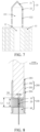
FIG. 6 is a cross-sectional view of an airflow heating assembly from a perspective according to an embodiment of this application; -
FIG. 7 is a cross-sectional view of an air guiding element and a piercing heating element in an airflow heating assembly from a perspective according to an embodiment of this application; -
FIG. 8 is a cross-sectional view of an aerosol generating device from a perspective according to an embodiment of this application; and -
FIG. 9 is a cross-sectional view of an aerosol generating device from a perspective according to another embodiment of this application. - For ease of understanding of this application, this application is described in further detail below with reference to the accompanying drawings and specific embodiments. It should be noted that, when an element is expressed as "being fixed to" another element, the element may be directly on the another element, or one or more intermediate elements may exist between the element and the another element. When an element is expressed as "being connected to" another element, the element may be directly connected to the another element, or one or more intermediate elements may exist between the element and the another element. In the descriptions of this specification, orientation or position relationships indicated by the terms such as "up", "down", "inside", "outside", "vertical" and "horizontal" are based on orientation or position relationships shown in the accompanying drawings, and are used only for ease and brevity of illustration and description of this application, rather than indicating or implying that the mentioned apparatus or component must have a particular orientation or must be constructed and operated in a particular orientation. Therefore, such terms should not be construed as limiting of this application. In addition, terms such as "first" and "second" are only used to describe the objective and cannot be understood as indicating or implying relative importance.
- Unless otherwise defined, meanings of all technical and scientific terms used in this specification are the same as that usually understood by a person skilled in the technical field to which this application belongs. Terms used in the specification of this application are merely intended to describe objectives of the specific embodiments, but are not intended to limit this application. The term "and/or" used in this specification includes any or all combinations of one or more associated related listed items.
- In addition, technical features involved in different embodiments of this application described below may be combined together if there is no conflict.
- Referring to
FIG. 1 , theairflow heating assembly 100 includes anair guiding element 10 and aheating body 20. Theheating body 20 is connected to theair guiding element 10, theheating body 20 is configured to be electrically connected to an external power supply, and theheating body 20 is configured to heat theair guiding element 10. Theair guiding element 10 is configured to allow gas to flow through and heat the gas flowing through, to increase thermal energy of the gas. - In an embodiment of this application, the
air guiding element 10 is made of graphite or graphite alloy. Theair guiding element 10 made of graphite or graphite alloy has good heat conductivity. Theheating body 20 directly heats theair guiding element 10, so that theair guiding element 10 can be heated to a preset temperature within short time, for example, theair guiding element 10 can be heated to above 300°C in 25s. - For the foregoing
air guiding element 10, refer toFIG. 1 and FIG. 2 . Theair guiding element 10 is provided with at least onefirst mounting cavity 12 and a plurality ofair guiding channels 11. Thefirst mounting cavity 12 is arranged inside theair guiding element 10, and thefirst mounting cavity 12 is configured to mount theheating body 20. Theair guiding channel 11 goes through theair guiding element 10 in an axial direction of theair guiding element 10, and theair guiding channel 11 is configured for gas to circulate. When theheating body 20 is in an operating state, and is heating theair guiding element 10, the gas passing through theair guiding channel 11 is heated by theair guiding element 10 to form a hot airflow, and the hot airflow flows to an interior of the aerosol generating article for heating, where a temperature of the hot airflow ranges from 200°C to 400°C. - In some embodiments, the plurality of
air guiding channels 11 are in a cylindrical shape. Specifically, a diameter D1 of theair guiding channel 11 satisfies: 0 < D1 ≤ 0.5 mm. According to the solution of theair guiding channel 11 with the small diameter, a quantity of theair guiding channels 11 can be increased in limited space of theair guiding element 10, and heating efficiency of the gas flowing through theair guiding channel 11 can be improved, to avoid a poor heating effect of the gas caused by a large flow rate of the gas because theair guiding channel 11 is excessively large. - In some embodiments, a ratio of a sum of areas of cross-sections of the plurality of
air guiding channels 11 to an area of a cross-section of theair guiding element 10 is greater than or equal to 1/5. The cross-sections of theair guiding channels 11 are within the cross-section of theair guiding element 10, and the cross-sections of theair guiding channels 11 and the cross-section of theair guiding element 10 are all perpendicular to a central line of theair guiding element 10. On a premise of ensuring a structural stability of theair guiding element 10, a ratio of an area of the cross-sections of theair guiding channels 11 to the area of the cross-section of theair guiding element 10 being closer to 1 indicates that an effective area of theair guiding channel 11 is larger, and a flow area available for gas is larger; and that when an area of a cross-section of a singleair guiding channel 11 is determined, a larger quantity ofair guiding channels 11 can be arranged on theair guiding element 10. - In some embodiments, the plurality of
air guiding channels 11 are arranged around a center of theair guiding element 10 in a plurality of circles, and a ratio of a quantity ofair guiding channels 11 located on an inner circle to a quantity ofair guiding channels 11 located on an outer circle is equal to a ratio of a radius of the inner circle to a radius of the outer circle. In a direction from the center of the cross-section of theair guiding element 10 to an edge of the cross-section of theair guiding element 10, a quantity ofair guiding channels 11 that can be arranged increases, so that flowing channels of the gas can be increased. In some embodiments, the plurality ofair guiding channels 11 are arranged in a circumferential array, to be specific, distances between two adjacentair guiding channels 11 located on a same circle are the same. - In some embodiments, referring to
FIG. 2 andFIG. 8 , theair guiding element 10 meets at least one of the following conditions: - (1) a diameter D3 of the
air guiding element 10 is: 4 mm ≤ D3 ≤ 8 mm; - (2) the diameter D3 of the
air guiding element 10 is: 6 mm ≤ D3 ≤ 7 mm; - (3) a cross-sectional area S1 of the
air guiding element 10 is 10 mm2 ≤ S1 ≤ 50 mm2; - (4) the cross-sectional area S1 of the
air guiding element 10 is 25 mm2 ≤ S1 ≤ 35 mm2; - (5) an axial length L1 of the
air guiding element 10 is: 5 mm ≤ L1 ≤ 10 mm; and - (6) the axial length L1 of the
air guiding element 10 is: 7 mm ≤ L1 ≤ 9 mm. - In some other embodiments, the
air guiding channel 11 may be in an irregular shape, and theair guiding channel 11 may be in a linear array, a ray array, or randomly distributed on theair guiding element 10. - It should be noted that, that the first mounting
cavity 12 is arranged inside theair guiding element 10 may be understood as that the first mountingcavity 12 is formed by being recessed from an outer surface of theair guiding element 10 to an inside of theair guiding element 10, or theair guiding element 10 is formed by splicing two or more split members, and a chamber or a gap for mounting theheating body 20 is formed between the two adjacent split members. For details, refer to the following embodiments. - In some embodiments, referring to
FIG. 3 , theair guiding element 10 includes a firstair guiding block 13 and a secondair guiding block 14. The firstair guiding block 13 and the secondair guiding block 14 are sequentially arranged in an extending direction of the central line of theair guiding element 10, in other words, an end surface of the firstair guiding block 13 is arranged opposite to an end surface of the secondair guiding block 14. A first mountingcavity 12 is formed between the firstair guiding block 13 and the secondair guiding block 14, and theheating body 20 is arranged in the first mountingcavity 12. Specifically, theheating body 20 located between the firstair guiding block 13 and the secondair guiding block 14 is in a shape of a sheet, and may be a Mesh heating mesh, a metal sheet, a flexible heating film, or the like. - In some embodiments, referring to
FIG. 4 , the air guiding block includes a firstair guiding block 13 and a secondair guiding block 14. The firstair guiding block 13 and the secondair guiding block 14 are sequentially arranged perpendicular to the extending direction of the central line of theair guiding element 10, in other words, a side surface of the firstair guiding block 13 and a side surface of the secondair guiding block 14 are arranged opposite to each other. A first mountingcavity 12 is formed between the firstair guiding block 13 and the secondair guiding block 14, and theheating body 20 is arranged in the first mountingcavity 12. Specifically, theheating body 20 is in a shape of a sheet, or theheating body 20 may be wound into a rod shape, and may be specifically a Mesh heating mesh, a metal sheet, or a flexible heating film. - In some other embodiments, the air guiding block includes a first
air guiding block 13 and a secondair guiding block 14. The firstair guiding block 13 is provided with a through groove, the secondair guiding block 14 is arranged in the through groove, a gap formed between the firstair guiding block 13 and the secondair guiding block 14 is a first mountingcavity 12, and theheating body 20 is arranged in the first mountingcavity 12. In some embodiments, theheating body 20 is in a shape of a cylinder or a ring, theheating body 20 is sleeved on an outer surface of the secondair guiding block 14, and then theheating body 20 and the secondair guiding block 14 are mounted in the through groove. In some other embodiments, theheating body 20 is a resistor heating wire, the resistor heating wire is wound around the outer surface of the secondair guiding block 14, and then the resistor heating wire and the secondair guiding block 14 are mounted in the through groove. In some other embodiments, theheating body 20 may alternatively be a MESH metal mesh, a heating film, or the like. - Certainly, in some other embodiments, the
air guiding element 10 may include a plurality of air guiding blocks. The plurality of air guiding blocks are stacked up and down in the extending direction of the central line of theair guiding element 10, or the plurality of air guiding blocks are stacked left and right perpendicular to the extending direction of the central line of theair guiding element 10. Theheating body 20 is arranged at a gap between the two adjacent air guiding blocks, and theheating body 20 respectively heats the two adjacent air guiding blocks. - For the foregoing first mounting
cavity 12, referring toFIG. 1 and FIG. 2 , the first mountingcavity 12 is arranged at the center of theair guiding element 10, and theheating body 20 is arranged in the first mountingcavity 12. Theheating body 20 is arranged at the center of theair guiding element 10, so that a feature that theheating body 20 generates heat in a spot-shaped manner is effectively used, and heating is performed outward from the center of theair guiding element 10 in a radial direction, so that heat dissipation of theheating body 20 can be greatly reduced, and thermal efficiency of theairflow heating assembly 100 can be improved. - In some embodiments, the first mounting
cavity 12 may be tubular, and a diameter D2 of the first mountingcavity 12 satisfies: 0 mm < D2 ≤ 2.5 mm. On a premise that theheating body 20 can be mounted in the first mountingcavity 12, a smaller diameter of the first mountingcavity 12 can release more space for theair guiding element 10, to increase the quantity of theair guiding channels 11. To achieve a better effect of releasing space, the diameter D2 of the first mountingcavity 12 may further satisfy 0 mm < D2 ≤ 1.7 mm. - In some embodiments, the first mounting
cavity 12 may alternatively be a flat groove, and the flat groove may be arranged transversely on theair guiding element 10, or may be arranged vertically on theair guiding element 10. The flat groove may allow the sheet-shapedheating body 20 to be inserted. Specifically, the sheet-shapedheating body 20 may be a resistor heating sheet including a metal material. In this way, space of theair guiding element 10 occupied by the first mountingcavity 12 can be reduced, and theheating body 20 and theair guiding element 10 can also be attached as much as possible to maintain better contact, which is beneficial to improving the heating efficiency. - In some embodiments, there are a plurality of first mounting
cavities 12 and a plurality ofheating bodies 20, and the plurality ofheating bodies 20 are arranged in the plurality of first mountingcavities 12. The plurality of first mountingcavities 12 may be arranged around the center of theair guiding element 10, may be linearly arranged, or may be randomly arranged. The plurality ofheating bodies 20 are arranged in theair guiding element 10, so that duration required for heating theair guiding element 10 can be effectively reduced, and the thermal efficiency of theairflow heating assembly 100 is improved. - In some embodiments, an inner surface of the first mounting
cavity 12 and an outer surface of theheating body 20 are at least partially attached to each other, to reduce a gap between the outer surface of theheating body 20 and the inner surface of the first mountingcavity 12, and enhance an effect of direct heating of theair guiding element 10 by theheating body 20. Specifically, a flat heating wire may be used as the heating body, so that an outer surface of the heating wire after spiraling can be in a flat state. When the spiral heating wire is mounted in the first mountingcavity 12, the outer surface of the heating wire can be attached to the inner surface of the first mountingcavity 12, so that heat generated by the heating wire can be directly transferred to theair guiding element 10, to reduce heat loss. - In some embodiments, the first mounting
cavity 12 goes through theair guiding element 10, the first mountingcavity 12 is configured to mount theheating body 20, and the first mountingcavity 12 may further allow airflow to circulate, thereby increasing a channel of the airflow in theair guiding element 10. In some embodiments, the first mountingcavity 12 may alternatively be provided as a blind hole, to facilitate fixing theheating body 20 in the first mountingcavity 12, and prevent gas located in the first mountingcavity 12 from directly entering the aerosol generating article after being heated by theheating body 20, causing a user to feel burning in the mouth when inhaling smoke generated by the aerosol generating article. - In some embodiments, the
heating body 20 and the first mountingcavity 12 may only partially overlap, and the first mountingcavity 12 may alternatively be arranged in only a partial area of theair guiding element 10. For example, an axial length of theheating body 20 inserted into the first mountingcavity 12 is at least 1/3 of the axial length of the air guiding element. - In some embodiments, referring to
FIG. 6 , an inner wall of the first mountingcavity 12 is provided with an abuttingportion 122. The abuttingportion 122 is configured to abut against an end of theheating body 20, to facilitate mounting of theheating body 20, and the abuttingportion 122 cooperates with other components to fix theheating body 20 in the first mountingcavity 12. In some embodiments, the abuttingportion 122 may be a step surface. In some embodiments, the inner wall of the first mountingcavity 12 is provided with a clamping slot, and the clamping slot is configured to be clamped with theheating body 20, so that theheating body 20 can be fixed in the first mountingcavity 12. - In some embodiments, referring to
FIG. 5 and FIG. 6 , theheating body 20 is provided with aventilation air gap 21. Theventilation air gap 21 increases a path for gas in the first mountingcavity 12, increases a path for gas directly or indirectly heated by theheating body 20, and improves utilization of hot gas. Theventilation air gap 21 of theheating body 20 is formed in a plurality of manners, and for some manners, refer to the following embodiments. - For example, a first hollow groove is arranged inside the
heating body 20, and at least a top of the first hollow groove is in communication with theair guiding element 10, and/or at least the top of the first hollow groove is in communication with a bottom of the aerosol generating article. The first hollow groove forms theventilation air gap 21 of theheating body 20, and the first hollow groove is configured for the gas in the first mountingcavity 12 to circulate, to increase a path for the gas, so that the gas directly heated by theheating body 20 flows to the inside of the aerosol generating article. Further, several protrusions may be provided on the inner wall surface of the first hollow groove. The several protrusions are configured to change a direction of airflow in the first hollow groove, so that gas flowing in the first hollow groove flows in an "S" shape, to increase heat absorbed by the gas, to prevent the airflow from entering the aerosol generating article excessively fast when the airflow is much lower than a preset heating temperature. - For example, the first hollow groove and a plurality of first through holes going through a side wall surface of the
heating body 20 are arranged in theheating body 20. The first hollow groove and the plurality of first through holes jointly form theventilation air gap 21 of theheating body 20. The plurality of first through holes are in communication with theair guiding channel 11 of theair guiding element 10, so that the gas inside theheating body 20 flows to the inside of the aerosol generating article through theair guiding channel 11 after being heated. - For example, an outer peripheral surface of the
heating body 20 is provided with several grooves. When theheating body 20 is mounted in the first mountingcavity 12, the grooves and the inner surface of the first mountingcavity 12 jointly form theventilation air gap 21. Theheating body 20 heats theair guiding element 10 and directly heats gas flowing through the grooves, thereby increasing a path for the gas. - In some embodiments, referring to
FIG. 5 and FIG. 6 , theheating body 20 is formed through spiraling of a heating wire, and the heating wire forms a plurality ofventilation air gaps 21 during spiraling. It may be understood that theheating body 20 may be partially helical, or may be entirely helical. - Specifically, the
heating body 20 may alternatively be a double helix structure. Afirst spiral layer 22 and asecond spiral layer 23. Thesecond spiral layer 23 is arranged outside thefirst spiral layer 22, and a pitch of thesecond spiral layer 23 is greater than a pitch of thefirst spiral layer 22 along an axial direction of a central line of thespiral heating body 20, so that theheating body 20 is in a screw-shape. Aspiral fixing groove 123 is arranged on the inner wall surface of the first mountingcavity 12, and thespiral fixing groove 123 is configured to be helically connected to thesecond spiral layer 23, so that theheating body 20 can be directly fixed in the first mountingcavity 12. This reduces components for fixing theheating body 20, and helps reduce a volume of theairflow heating assembly 100. - For example, the
heating body 20 is provided with a clampingportion 24. After theheating body 20 is inserted into the first mountingcavity 12, the clampingportion 24 is clamped with the clamping slot of the first mountingcavity 12, to fix theheating body 20 in the first mounting slot. In some embodiments, the clamping slot is arranged at a mouth of the first mountingcavity 12, and the clampingportion 24 is arranged at an end of theheating body 20, so that theheating body 20 is clamped with the first mountingcavity 12 only at the mouth, and the part of theheating body 20 inserted into the first mountingcavity 12 can be directly attached to the inner surface of the first mountingcavity 12, to reduce heat loss of theheating body 20. - In some embodiments, referring to
FIG. 6 andFIG. 8 , theheating body 20 meets at least one of the following conditions: - (1) a diameter D4 of the
heating body 20 satisfies: 1 mm ≤ D4 ≤ 2 mm; - (2) the diameter D4 of the
heating body 20 satisfies: 1.4 mm ≤ D4 ≤ 1.7 mm; - (3) an area S2 enclosed by an outer contour of a cross-section of the
heating body 20 is: 0.7 mm2 ≤ S2 ≤ 3.5 mm2, where the cross-section of theair guiding element 10 is perpendicular to the central line of theair guiding element 10; and - (4) an axial length L2 of the
heating body 20 is: 4 mm ≤ L2 ≤ 9 mm. - In some embodiments, the
heating body 20 may be made of at least one of a metal material with proper impedance, a metal alloy, graphite, carbon, conductive ceramic, or a composite material of a ceramic material and a metal material. A suitable metal or alloy material includes at least one of nickel, cobalt, zirconium, titanium, nickel alloy, cobalt alloy, zirconium alloy, titanium alloy, nickel-chromium alloy, nickel-iron alloy, iron-chromium alloy, iron-chromium-aluminum alloy, titanium alloy, iron-manganese-aluminum-based alloy, stainless steel, or the like. - In some embodiments, referring to
FIG. 7 , theairflow heating assembly 100 further includes a piercingheating element 30. The piercingheating element 30 is arranged at an end of theair guiding element 10, and the piercingheating element 30 is configured to pierce and insert into a tobacco segment of the aerosol generating article, to transfer heat generated by theheating body 20 to the aerosol generating article. - The piercing
heating element 30 includes a piercingportion 31 and a mountingportion 32. An end of the mountingportion 32 is connected to theair guiding element 10, and the other end of the mountingportion 32 is connected to the piercingportion 31. The piercingportion 31 is configured to pierce an air inlet end of the tobacco segment of the aerosol generating article. A second mountingcavity 321 is arranged in the mountingportion 32, and the second mountingcavity 321 is in communication with the first mountingcavity 12. Theheating body 20 is arranged in the first mountingcavity 12 and the second mountingcavity 321, and theheating body 20 is configured to simultaneously heat theair guiding element 10, the mountingportion 32, and the piercingportion 31. A through-goingventilation hole 322 is arranged on a side wall surface of the mountingportion 32, and the second mountingcavity 321 is in communication with the outside through theventilation hole 322, so that after the piercingheating element 30 is inserted into the interior of the aerosol generating article, heated gas enters the second mountingcavity 321 from the first mountingcavity 12, and then passes through theventilation hole 322 to enter the interior of the aerosol generating article, thereby completing a process of heating the aerosol generating article. - In some embodiments, referring to
FIG. 8 , theairflow heating assembly 100 further includes acover plate 40. Thecover plate 40 is arranged at the other end of theair guiding element 10, and thecover plate 40 is configured to cooperate with the abuttingportion 122 in the first mountingcavity 12, to fix theheating body 20 in the first mountingcavity 12. At least a part of thecover plate 40 may be made of ceramic, which can effectively insulate heat. Similarly, the abutting portion may alternatively be formed by at least a part of theair guiding element 10, or may be formed by the heating body arranged inside the first mountingcavity 12. - In some embodiments, referring to
FIG. 8 , theairflow heating assembly 100 further includes a heat preservation assembly. Theheat preservation assembly 200 includes aninner tube portion 202 and anouter tube portion 203. Anaccommodating cavity 201 is arranged in an inner tube wall. A mounting structure matching theair guiding element 10 may be further arranged in the inner tube wall, so that theair guiding element 10 can be assembled inside the inner tube wall, and an aerosol generating article is inserted into and nearly attached to theaccommodating cavity 201. Theouter tube portion 203 is sleeved outside theinner tube portion 202. Acavity 204 is enclosed between theinner tube portion 202 and theouter tube portion 203, and thecavity 204 has a specific vacuum inside, or is filled with an inert gas with low heat conductivity, or is filled with a solid medium or a liquid medium with low heat conductivity. It may be understood that, "nearly attached" indicates that a distance between theinner tube portion 202 and the aerosol generating article is expected to be as small as possible. This helps assist in heating the circumferential outer surface of the aerosol generating article by using a remaining temperature of theinner tube portion 202, and can complement baking of the outer surface of the aerosol generating article, so that the baking of the aerosol generating article is more thorough and uniform. Specifically, a minimum distance between theinner tube portion 202 and the outer surface of the aerosol generating article is within 1 mm, preferably 0.5 mm. Thecavity 204 of theheat preservation assembly 200 can reduce the amount of heat transferred by theinner tube portion 202 to theouter tube portion 203, so that theheat preservation assembly 200 also has a heat preservation function for the airflow heating assembly, and there is no need to add another heat preservation measure or assembly, which is beneficial to reducing costs and simplifying the structure. - In some embodiments, referring to
FIG. 9 , theheat preservation assembly 200 may alternatively be a single-layer tube, such as a metal tube or a ceramic tube, and can absorb a part of heat of theair guiding element 10, and convert the heat into supplementary heating for the aerosol generating article. Therefore, heat can be dissipated quickly, and power consumption can be reduced. - The
airflow heating assembly 100 in the embodiments of this application includes anair guiding element 10 and aheating body 20. A first mountingcavity 12 is provided inside theair guiding element 10, theair guiding element 10 is provided with a plurality of through-goingair guiding channels 11, and theair guiding channels 11 are configured for gas to circulate; and theheating body 20 is arranged in the first mountingcavity 12, where theheating body 20 is configured to be electrically connected to an external power supply to heat theair guiding element 10, so that theair guiding element 10 heats gas flowing through theair guiding channels 11. Theheating body 20 is arranged inside theair guiding element 10, so that a problem of aconventional heating body 20 emitting some heat outwards due to the fact that theheating body 20 is sleeved outside theair guiding element 10 can be effectively resolved, and heating efficiency of theheating body 20 can be improved. - This application further provides an embodiment of an
aerosol generating device 1000. Referring toFIG. 8 , theaerosol generating device 1000 is configured to be inserted with an aerosol generating article and heat the aerosol generating article to generate aerosols. Theaerosol generating device 1000 includes ahousing 200 and the foregoingairflow heating assembly 100. Thehousing 200 is provided with anaccommodating cavity 201. At least a part of the aerosol generating article is removably arranged in theaccommodating cavity 201. Theairflow heating assembly 100 is arranged in theaccommodating cavity 201, and theairflow heating assembly 100 is arranged at an upstream airflow position of the aerosol generating article, so that air passing through theairflow heating assembly 100 enters the interior of the aerosol generating article for heating after being heated. For a function and a structure of theairflow heating assembly 100, refer to the foregoing embodiments. - In some embodiments, the housing may be a heat preservation component, or a heat preservation component may be arranged inside the housing. For example, the heat preservation component is in a shape of a hollow cylinder, and may be made of a vacuum tube or a high-temperature-resistant material such as Peek or aerogel. The heat preservation component may be configured to reduce heat generated by the airflow heating assembly to be transferred along a direction of the housing, to prevent the user from being scalded due to an excessively high temperature in an area outside the airflow heating assembly in contact with the user.
- The foregoing descriptions are merely embodiments of this application, and the protection scope of this application is not limited thereto. All equivalent structure or process changes made according to the content of this specification and accompanying drawings in this application or by directly or indirectly applying this application in other related technical fields shall fall within the protection scope of the present invention.
Claims (24)
- An airflow heating assembly, configured to heat an aerosol generating article to generate an aerosol, wherein the airflow heating assembly comprises:an air guiding element, wherein a first mounting cavity is provided inside the air guiding element, the air guiding element is provided with a plurality of through-going air guiding channels, and the air guiding channels are configured for gas to circulate; anda heating body, arranged in the first mounting cavity, wherein the heating body is configured to be electrically connected to an external power supply to heat the air guiding element, so that the air guiding element heats gas flowing through the air guiding channels.
- The airflow heating assembly according to claim 1, wherein a diameter D1 of the air guiding channel satisfies: 0 < D1 ≤ 0.5 mm; or
a diameter D2 of the first mounting cavity satisfies: 0 mm < D2 ≤ 2.5 mm. - The airflow heating assembly according to claim 1, wherein a ratio of a total area of cross-sections of the plurality air guiding channels to an area of a cross-section of the air guiding element is greater than or equal to 1/5, wherein
the cross-sections of the air guiding channels overlap with the cross-section of the air guiding element, and the cross-sections of the air guiding channels and the cross-section of the air guiding element are all perpendicular to a central line of the air guiding element. - The airflow heating assembly according to claim 1, wherein the plurality of air guiding channels are arranged on a plurality of circles around a center of the air guiding element, and distances between two adjacent air guiding channels located on a same circle are the same.
- The airflow heating assembly according to claim 4, wherein a ratio of a quantity of air guiding channels located on an inner circle to a quantity of air guiding channels located on an outer circle is equal to a ratio of a radius of the inner circle to a radius of the outer circle.
- The airflow heating assembly according to claim 1, wherein the air guiding element meets at least one of the following conditions: a cross-sectional area S1 of the air guiding element is: 10 mm2 ≤ S1 ≤ 50 mm2, wherein a cross-section of the air guiding element is perpendicular to a central line of the air guiding element; or
an axial length L1 of the air guiding element is: 5 mm ≤ L1 ≤ 10 mm. - The airflow heating assembly according to claim 1, wherein the heating body meets at least one of the following conditions: an area S2 enclosed by an outer contour of a cross-section of the heating body is: 0.7 mm2 ≤ S2 ≤ 3.5 mm2, wherein a cross-section of the air guiding element is perpendicular to a central line of the air guiding element; or
an axial length L2 of the heating body is: 4 mm ≤ L2 ≤ 9 mm. - The airflow heating assembly according to claim 1, wherein the first mounting cavity meets at least one of the following conditions:the first mounting cavity is arranged at a center of the air guiding element;the first mounting cavity goes through the air guiding element; andthe first mounting cavity is a blind hole.
- The airflow heating assembly according to claim 1, wherein there are a plurality of heating bodies and a plurality of first mounting cavities, and the plurality of heating bodies are arranged in the plurality of first mounting cavities.
- The airflow heating assembly according to claim 1, wherein an outer surface of the heating body and an inner surface of the first mounting cavity are at least partially attached to each other.
- The airflow heating assembly according to claim 1, wherein the heating body has a ventilation air gap; andthe ventilation air gap comprises at least a first hollow groove and/or several grooves, whereinthe first hollow groove is arranged inside the heating body, and at least a top of the first hollow groove is in communication with the air guiding element, or at least a top of the first hollow groove is in communication with a bottom of the aerosol generating article, or at least a side surface of the first hollow groove is in communication with the heating body to form a plurality of first through holes; andthe groove is arranged on an outer peripheral surface of the heating body, and the groove and an inner surface of the first mounting cavity jointly form the ventilation air gap for gas to circulate.
- The airflow heating assembly according to claim 11, wherein the heating body is at least partially formed through spiraling of a heating wire, and a plurality of ventilation air gaps are formed during the spiraling of the heating wire.
- The airflow heating assembly according to claim 1, wherein a shape of a cross-section of the heating wire is a rectangle, wherein the cross-section of the heating wire is perpendicular to an extension direction of an unfolded heating wire; or
a shape of the heating body is a sheet. - The airflow heating assembly according to claim 1, wherein the heating body is provided with a clamping portion, an inner surface of the first mounting cavity is provided with a clamping slot, and the heating body is clamped with the clamping slot of the first mounting cavity through the clamping portion, to fix the heating body in the first mounting cavity.
- The airflow heating assembly according to claim 1, further comprising a cover plate, and at least one of the air guiding element, an inner wall of the first mounting cavity, and/or the heating body is provided with an abutting portion, to fix the heating body in the first mounting cavity.
- The airflow heating assembly according to claim 1, wherein an axial length of the heating body inserted into the first mounting cavity is at least 1/3 of an axial length of the air guiding element.
- The airflow heating assembly according to claim 1, wherein the air guiding element comprises a first air guiding block and a second air guiding block, the heating body is arranged between the first air guiding block and the second air guiding block, and arrangement of the first air guiding block and the second air guiding block meets at least one of the following conditions:the first air guiding block and the second air guiding block are arranged up and down in an extending direction of a central line of the air guiding element;the first air guiding block and the second air guiding block are arranged left and right perpendicular to the extending direction of the central line of the air guiding element; andthe first air guiding block is provided with a groove, and the second air guiding block is sleeved in the groove.
- The airflow heating assembly according to claim 1, wherein the airflow heating assembly further comprises a piercing heating element, the piercing heating element is arranged at an end of the air guiding element, the air guiding element is provided with a first mounting cavity, the heating body is arranged in the first mounting cavity, the heating body is configured to heat the piercing heating element and the air guiding element, and the piercing heating element is configured to be inserted into the aerosol generating article to heat the aerosol generating article.
- The airflow heating assembly according to claim 18, wherein the piercing heating element comprises a piercing portion and a mounting portion, an end of the mounting portion is connected to the air guiding element, the piercing portion is arranged at another end of the mounting portion, a second mounting cavity is provided in the mounting portion, the second mounting cavity is in communication with the first mounting cavity, and the heating body is arranged in the first mounting cavity and the second mounting cavity.
- The airflow heating assembly according to claim 19, wherein a ventilation hole is provided on a side wall of the piercing heating element in contact with the aerosol generating article.
- The airflow heating assembly according to claim 1, wherein
the air guiding element is made of graphite or graphite alloy. - The airflow heating assembly according to claim 1, further comprising a heat preservation assembly connected to the air guiding element, wherein an accommodating cavity is arranged in the heat preservation assembly, and the accommodating cavity is configured to accommodate the aerosol generating article, whereinthe heat preservation assembly comprises an inner tube portion and an outer tube portion, the accommodating cavity is arranged inside the inner tube portion, the outer tube portion is arranged around the inner tube portion, a cavity is enclosed between the outer tube portion and the inner tube portion, and the inner tube portion is nearly attached to the aerosol generating article; orthe heat preservation assembly is a single-layer tube, an interior of the single-layer tube is nearly attached to the aerosol generating article, and the single-layer tube is a metal tube or a ceramic tube.
- An airflow heating assembly, configured to heat an aerosol generating article to generate an aerosol, wherein the airflow heating assembly comprises:an air guiding element, wherein a first mounting cavity is provided in the air guiding element, the air guiding element is provided with a plurality of through-going air guiding channels, and the air guiding channels are configured to allow gas to circulate; anda resistor heating body, arranged in the first mounting cavity, wherein the heating body is configured to be electrically connected to an external power supply to heat the air guiding element, so that the air guiding element heats gas flowing through the air guiding channels, whereinthe air guiding element is made of graphite or graphite alloy.
- An aerosol generating device, configured to heat an aerosol generating article to generate an aerosol, wherein the aerosol generating device comprises:a housing, provided with an accommodating cavity in the housing, wherein the accommodating cavity is configured for removably arranging the aerosol generating article; andthe airflow heating assembly according to any one of claims 1 to 23, wherein the airflow heating assembly is arranged in the accommodating cavity, and the airflow heating assembly is arranged at an upstream airflow position of the aerosol generating article, so that air passing through the airflow heating assembly enters the aerosol generating article after being heated.
Applications Claiming Priority (2)
| Application Number | Priority Date | Filing Date | Title |
|---|---|---|---|
| CN202210802011.6A CN117397877A (en) | 2022-07-08 | 2022-07-08 | Airflow heating components and aerosol generation devices |
| PCT/CN2023/103803 WO2024007941A1 (en) | 2022-07-08 | 2023-06-29 | Airflow heating assembly and aerosol generating device |
Publications (2)
| Publication Number | Publication Date |
|---|---|
| EP4537683A1 true EP4537683A1 (en) | 2025-04-16 |
| EP4537683A4 EP4537683A4 (en) | 2025-09-24 |
Family
ID=89454254
Family Applications (1)
| Application Number | Title | Priority Date | Filing Date |
|---|---|---|---|
| EP23834708.2A Pending EP4537683A4 (en) | 2022-07-08 | 2023-06-29 | Airflow heating arrangement and aerosol generation device |
Country Status (5)
| Country | Link |
|---|---|
| EP (1) | EP4537683A4 (en) |
| JP (1) | JP2025521991A (en) |
| KR (1) | KR20250018399A (en) |
| CN (1) | CN117397877A (en) |
| WO (1) | WO2024007941A1 (en) |
Family Cites Families (14)
| Publication number | Priority date | Publication date | Assignee | Title |
|---|---|---|---|---|
| KR102116961B1 (en) * | 2017-07-21 | 2020-06-02 | 주식회사 아모센스 | heater assembly for cylinderical type electronic cigarette and cylinderical type electronic cigarette including the same |
| CN109674095B (en) * | 2019-01-26 | 2025-04-29 | 深圳市合元科技有限公司 | Cigarette heaters and electric heating smoking devices, thermal insulation devices |
| CN212117064U (en) * | 2019-12-09 | 2020-12-11 | 深圳市合元科技有限公司 | Heat insulation mechanism for gas mist generating device and gas mist generating device |
| CN111920098A (en) * | 2020-08-03 | 2020-11-13 | 惠州市沛格斯科技有限公司 | Heating module and smoke generating device |
| CN111838774A (en) * | 2020-08-03 | 2020-10-30 | 惠州市沛格斯科技有限公司 | Heating Modules and Smoking Devices |
| CN111772246A (en) * | 2020-08-03 | 2020-10-16 | 惠州市沛格斯科技有限公司 | Heating module and smoking device |
| CN214127020U (en) * | 2020-09-22 | 2021-09-07 | 深圳市新宜康科技股份有限公司 | Double heating low temperature tobacco heating device |
| CN112089113B (en) * | 2020-10-13 | 2024-11-19 | 惠州市沛格斯科技有限公司 | Heating module and smoke generating device |
| CN214802329U (en) * | 2020-10-14 | 2021-11-23 | 深圳市艾溹技术研究有限公司 | Electronic cigarette heater and electronic cigarette |
| CN112137179B (en) * | 2020-10-14 | 2025-11-07 | 深圳市艾溹技术研究有限公司 | Electronic cigarette heater prepared by adopting preparation method of electronic cigarette heater and electronic cigarette |
| KR102637742B1 (en) * | 2020-11-25 | 2024-02-19 | 주식회사 케이티앤지 | Aerosol generating device |
| CN215958332U (en) * | 2021-07-21 | 2022-03-08 | 深圳麦克韦尔科技有限公司 | Electronic atomization device and atomizer and electrode connecting device thereof |
| CN217986690U (en) * | 2022-07-08 | 2022-12-09 | 深圳市合元科技有限公司 | Airflow heating assembly and aerosol generating device |
| CN115553507B (en) * | 2022-10-25 | 2025-07-25 | 四川三联新材料有限公司 | Airflow heating assembly and aerosol generating device |
-
2022
- 2022-07-08 CN CN202210802011.6A patent/CN117397877A/en active Pending
-
2023
- 2023-06-29 EP EP23834708.2A patent/EP4537683A4/en active Pending
- 2023-06-29 KR KR1020247043522A patent/KR20250018399A/en active Pending
- 2023-06-29 WO PCT/CN2023/103803 patent/WO2024007941A1/en not_active Ceased
- 2023-06-29 JP JP2025500877A patent/JP2025521991A/en active Pending
Also Published As
| Publication number | Publication date |
|---|---|
| JP2025521991A (en) | 2025-07-10 |
| KR20250018399A (en) | 2025-02-05 |
| CN117397877A (en) | 2024-01-16 |
| EP4537683A4 (en) | 2025-09-24 |
| WO2024007941A1 (en) | 2024-01-11 |
Similar Documents
| Publication | Publication Date | Title |
|---|---|---|
| CN216701672U (en) | Atomizer and electronic atomization device | |
| CN113729288A (en) | Heating assembly and aerosol generating device | |
| US20240225099A1 (en) | Aerosol generation device and system | |
| JP7514273B2 (en) | Heating module and aerosol generating device | |
| CN109330030A (en) | Cigarette heaters, electrically heated smoking devices and thermal insulation components | |
| US20230380501A1 (en) | Vaporizer and electronic vaporization device | |
| JP2024000501A (en) | Aerosol generator and its heating module | |
| CN113729287A (en) | Guide member, heating unit, and aerosol generating device | |
| WO2023125680A1 (en) | Electrically heated aerosol generating system | |
| CN111449300A (en) | Electronic atomizing device, atomizer and atomizing assembly therefor | |
| CN207383539U (en) | A kind of heating member and cigarette heating unit | |
| CN219613080U (en) | Atomizing core, atomizer and aerosol generating device | |
| CN209628627U (en) | Cigarette heater, electrically heated cigarette smoking device and insulating assembly | |
| CN217986690U (en) | Airflow heating assembly and aerosol generating device | |
| US20230136231A1 (en) | Atomizing unit and atomizing device | |
| US12557845B2 (en) | Electronic atomization device and atomizer and atomization assembly thereof | |
| CN216293010U (en) | Heating assembly and aerosol generating device | |
| CN217958771U (en) | Aerosol generating device and heating assembly thereof | |
| CN216293011U (en) | Guide member, heating unit, and aerosol generating device | |
| US20230301361A1 (en) | Vaporizer and electronic vaporization apparatus | |
| WO2024007941A1 (en) | Airflow heating assembly and aerosol generating device | |
| CN218790580U (en) | Liquid guide assembly, heating assembly, atomizer and electronic atomization device | |
| EP4537684A1 (en) | Heating device, aerosol generating device, and aerosol generating system | |
| CN113558289B (en) | Cooling elements, cooling filters and heat-not-burn smoking articles | |
| CN224069775U (en) | Atomizing core and electron cigarette of taking a breath steadily |
Legal Events
| Date | Code | Title | Description |
|---|---|---|---|
| STAA | Information on the status of an ep patent application or granted ep patent |
Free format text: STATUS: THE INTERNATIONAL PUBLICATION HAS BEEN MADE |
|
| PUAI | Public reference made under article 153(3) epc to a published international application that has entered the european phase |
Free format text: ORIGINAL CODE: 0009012 |
|
| STAA | Information on the status of an ep patent application or granted ep patent |
Free format text: STATUS: REQUEST FOR EXAMINATION WAS MADE |
|
| 17P | Request for examination filed |
Effective date: 20250107 |
|
| AK | Designated contracting states |
Kind code of ref document: A1 Designated state(s): AL AT BE BG CH CY CZ DE DK EE ES FI FR GB GR HR HU IE IS IT LI LT LU LV MC ME MK MT NL NO PL PT RO RS SE SI SK SM TR |
|
| A4 | Supplementary search report drawn up and despatched |
Effective date: 20250826 |
|
| RIC1 | Information provided on ipc code assigned before grant |
Ipc: A24F 40/46 20200101AFI20250820BHEP Ipc: A24F 40/485 20200101ALI20250820BHEP Ipc: A24F 40/20 20200101ALN20250820BHEP |
|
| DAV | Request for validation of the european patent (deleted) | ||
| DAX | Request for extension of the european patent (deleted) |