EP4535976A2 - Control system for a sensor assembly - Google Patents
Control system for a sensor assembly Download PDFInfo
- Publication number
- EP4535976A2 EP4535976A2 EP24218906.6A EP24218906A EP4535976A2 EP 4535976 A2 EP4535976 A2 EP 4535976A2 EP 24218906 A EP24218906 A EP 24218906A EP 4535976 A2 EP4535976 A2 EP 4535976A2
- Authority
- EP
- European Patent Office
- Prior art keywords
- sensor assembly
- cleaning
- actuator
- contaminants
- frequency
- Prior art date
- Legal status (The legal status is an assumption and is not a legal conclusion. Google has not performed a legal analysis and makes no representation as to the accuracy of the status listed.)
- Pending
Links
Images




Classifications
-
- B—PERFORMING OPERATIONS; TRANSPORTING
- B08—CLEANING
- B08B—CLEANING IN GENERAL; PREVENTION OF FOULING IN GENERAL
- B08B7/00—Cleaning by methods not provided for in a single other subclass or a single group in this subclass
- B08B7/02—Cleaning by methods not provided for in a single other subclass or a single group in this subclass by distortion, beating, or vibration of the surface to be cleaned
- B08B7/026—Using sound waves
- B08B7/028—Using ultrasounds
-
- B—PERFORMING OPERATIONS; TRANSPORTING
- B60—VEHICLES IN GENERAL
- B60S—SERVICING, CLEANING, REPAIRING, SUPPORTING, LIFTING, OR MANOEUVRING OF VEHICLES, NOT OTHERWISE PROVIDED FOR
- B60S1/00—Cleaning of vehicles
- B60S1/02—Cleaning windscreens, windows or optical devices
- B60S1/56—Cleaning windscreens, windows or optical devices specially adapted for cleaning other parts or devices than front windows or windscreens
-
- G—PHYSICS
- G01—MEASURING; TESTING
- G01K—MEASURING TEMPERATURE; MEASURING QUANTITY OF HEAT; THERMALLY-SENSITIVE ELEMENTS NOT OTHERWISE PROVIDED FOR
- G01K13/00—Thermometers specially adapted for specific purposes
-
- G—PHYSICS
- G01—MEASURING; TESTING
- G01N—INVESTIGATING OR ANALYSING MATERIALS BY DETERMINING THEIR CHEMICAL OR PHYSICAL PROPERTIES
- G01N29/00—Investigating or analysing materials by the use of ultrasonic, sonic or infrasonic waves; Visualisation of the interior of objects by transmitting ultrasonic or sonic waves through the object
- G01N29/02—Analysing fluids
- G01N29/022—Fluid sensors based on microsensors, e.g. quartz crystal-microbalance [QCM], surface acoustic wave [SAW] devices, tuning forks, cantilevers, flexural plate wave [FPW] devices
-
- G—PHYSICS
- G01—MEASURING; TESTING
- G01N—INVESTIGATING OR ANALYSING MATERIALS BY DETERMINING THEIR CHEMICAL OR PHYSICAL PROPERTIES
- G01N29/00—Investigating or analysing materials by the use of ultrasonic, sonic or infrasonic waves; Visualisation of the interior of objects by transmitting ultrasonic or sonic waves through the object
- G01N29/02—Analysing fluids
- G01N29/036—Analysing fluids by measuring frequency or resonance of acoustic waves
-
- G—PHYSICS
- G01—MEASURING; TESTING
- G01N—INVESTIGATING OR ANALYSING MATERIALS BY DETERMINING THEIR CHEMICAL OR PHYSICAL PROPERTIES
- G01N29/00—Investigating or analysing materials by the use of ultrasonic, sonic or infrasonic waves; Visualisation of the interior of objects by transmitting ultrasonic or sonic waves through the object
- G01N29/34—Generating the ultrasonic, sonic or infrasonic waves, e.g. electronic circuits specially adapted therefor
- G01N29/348—Generating the ultrasonic, sonic or infrasonic waves, e.g. electronic circuits specially adapted therefor with frequency characteristics, e.g. single frequency signals, chirp signals
-
- G—PHYSICS
- G01—MEASURING; TESTING
- G01R—MEASURING ELECTRIC VARIABLES; MEASURING MAGNETIC VARIABLES
- G01R31/00—Arrangements for testing electric properties; Arrangements for locating electric faults; Arrangements for electrical testing characterised by what is being tested not provided for elsewhere
- G01R31/34—Testing dynamo-electric machines
-
- G—PHYSICS
- G02—OPTICS
- G02B—OPTICAL ELEMENTS, SYSTEMS OR APPARATUS
- G02B27/00—Optical systems or apparatus not provided for by any of the groups G02B1/00 - G02B26/00, G02B30/00
- G02B27/0006—Optical systems or apparatus not provided for by any of the groups G02B1/00 - G02B26/00, G02B30/00 with means to keep optical surfaces clean, e.g. by preventing or removing dirt, stains, contamination, condensation
-
- H—ELECTRICITY
- H10—SEMICONDUCTOR DEVICES; ELECTRIC SOLID-STATE DEVICES NOT OTHERWISE PROVIDED FOR
- H10N—ELECTRIC SOLID-STATE DEVICES NOT OTHERWISE PROVIDED FOR
- H10N30/00—Piezoelectric or electrostrictive devices
- H10N30/20—Piezoelectric or electrostrictive devices with electrical input and mechanical output, e.g. functioning as actuators or vibrators
-
- H—ELECTRICITY
- H10—SEMICONDUCTOR DEVICES; ELECTRIC SOLID-STATE DEVICES NOT OTHERWISE PROVIDED FOR
- H10N—ELECTRIC SOLID-STATE DEVICES NOT OTHERWISE PROVIDED FOR
- H10N30/00—Piezoelectric or electrostrictive devices
- H10N30/80—Constructional details
- H10N30/802—Circuitry or processes for operating piezoelectric or electrostrictive devices not otherwise provided for, e.g. drive circuits
-
- G—PHYSICS
- G01—MEASURING; TESTING
- G01N—INVESTIGATING OR ANALYSING MATERIALS BY DETERMINING THEIR CHEMICAL OR PHYSICAL PROPERTIES
- G01N2291/00—Indexing codes associated with group G01N29/00
- G01N2291/02—Indexing codes associated with the analysed material
- G01N2291/025—Change of phase or condition
- G01N2291/0256—Adsorption, desorption, surface mass change, e.g. on biosensors
Definitions
- This relates generally to a control system for a sensor assembly.
- Obstacle and collision avoidance systems are useful to mitigate damage to vehicles and other property due to collisions.
- Various technologies regarding obstacle and collision avoidance systems can be incorporated into vehicles at a reasonable cost.
- Some technologies include sensors and digital cameras for sensing and monitoring areas around the vehicle. In some cases, cameras can increase safety by being mounted in locations that can give drivers access to alternative perspectives, which are otherwise diminished or unavailable to the driver's usual view through windows or mirrors.
- One example includes a control system for a sensor that includes a contaminant detection subsystem that measures a resonant frequency of the sensor assembly, the sensor assembly including a housing, an actuator and a sensor both disposed in the housing, and a housing cover that enables sensing by the sensor therethrough, the contaminant detection subsystem detects contaminants on an exposed surface of the housing cover and provides a detection signal identifying contaminants on the housing cover based on the resonant frequency of the sensor assembly, and a cleaning subsystem that provides a cleaning control signal to the actuator to expel the contaminants from the housing cover in response to the detection signal.
- a contaminant sensing system that includes a sensor assembly disposed on an exterior of a vehicle, the sensor assembly including an actuator and a sensor both disposed in a housing that enables sensing by the sensor through the housing, a contaminant detection subsystem that measures a resonant frequency of the sensor assembly, the contaminant detection subsystem to provide a detection signal in response to detecting contaminants on an exposed surface of the housing, a cleaning subsystem that implements expelling the contaminants from the exposed surface in response to the detection signal, and a temperature regulating device that regulates power to the actuator based on a temperature of the actuator.
- the sensing and signaling control/monitoring system utilizes an actuator that vibrates the sensor assembly and consequently, drives a contaminant (e.g., water, mist, ice, dirt, mud, etc.) deposited on an exposed surface of a sensor assembly at its resonant frequency so as to facilitate the removal of the contaminant from the exposed surface. More specifically, when the actuator is excited by the proper periodic waveform, the actuator will vibrate the sensor assembly. Properly adjusting the frequency and amplitude of the vibration will expel the contaminant from the exposed surface.
- a contaminant e.g., water, mist, ice, dirt, mud, etc.
- the sensing and signaling control/monitoring system can be utilized with any sensor device disposed externally on the vehicle.
- some sensor devices include camera systems (e.g., camera monitoring systems (CMS), surround view systems (SVS)), photodetectors, external mirrors, reflectors, lasers (LiDAR).
- CMS camera monitoring systems
- SVS surround view systems
- Other types of sensor devices may include short-range and long-range radar, near-field transceiver, acoustic sensors or the like.
- the housing for the lens of cameras or other devices can include an exposed lens cover surface (such as camera, reflector, sensor, etc.).
- other types of sensors also include an external housing to protect the sensing devices from the environment.
- Each housing has an associated surface through which the signaling and/or sensing are provided to implement the corresponding sensing function (imaging, radar, LiDAR, near-field sensing, etc.).
- the sensing and signaling control/monitoring system not only cleans the housing, as described hereinabove, but also includes components to monitor other environmental or operating parameters for the sensor assembly. Examples of the environmental and operating parameters include temperature detection, fault detection (e.g., monitor the integrity and functionality of the exposed surface), power regulation, etc.
- the sensing and signaling control/monitoring system thus can extend the mechanical life of the sensor assembly and maintain its surface substantially free of contaminants.
- the sensing and signaling control/monitoring system may also provide early warnings for potential failures for the sensor assembly.
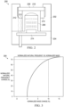
- FIG. 1 illustrates an example sensing and signaling control/monitoring system 100 and FIG. 2 is an example sensor assembly 200 that can be used with the sensing and signaling control/monitoring system 100.
- the sensing and signaling control/monitoring system 100 includes a contaminant detection subsystem 110 that measures a resonant frequency of a sensor assembly, a fault detection subsystem 130 that detects faults in the sensor assembly based on the change in the frequency of the sensor assembly, a cleaning subsystem 140 that provides a cleaning control signal to an actuator in the sensor assembly to expel contaminants from exposed surfaces of the sensor assembly, and a temperature monitoring/power regulation device 160 that monitors a temperature of the actuator.
- a controller 170 is provided to control the subsystems and devices via a bus 190.
- the actuator 210 can be a transducer (e.g., piezoelectric cylindrical or ring type transducer) that when excited by proper signaling, will vibrate the housing cover 208. As described herein, by correctly adjusting the frequency and/or the amplitude of the vibration the contaminants can be expelled from an exposed surface 216 of the housing cover 208.
- a transducer e.g., piezoelectric cylindrical or ring type transducer
- the contaminant detection subsystem 110 can be triggered manually (e.g., switch, push button, etc.) by an occupant of the vehicle.
- the contaminant detection subsystem 110 can be triggered by the sensor assembly if the sensor assembly senses that contaminants may be on the exposed surface.
- the triggering of the contaminant detection subsystem 110 can come from one of multiple sources.
- the frequency measurement circuit 114 monitors a change in a resonant frequency of the sensor assembly to detect the presence of contaminants disposed on the exposed surface of the sensor assembly.
- a shift in the resonant frequency indicates that contaminants are present on the exposed surface of the sensor assembly.
- ⁇ ⁇ n _ norm ⁇ ⁇ n ⁇ n is a normalized change in natural frequency
- ⁇ m norm ⁇ m m is a normalized change in mass both of which are unitless.
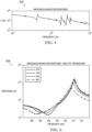
- FIG. 3 is an example plot 300 that illustrates a change in the normalized natural frequency versus a change in the normalized mass, as described hereinabove.
- the change in normalized natural frequency is very sensitive to a small change in normalized mass.
- a change in normalized mass of about 10% results in a change in normalized natural frequency of about 70%.
- the sensitivity of the change in the resonant or natural frequency is effective in detecting the presence of contaminants on the exposed surface. Detection of the contaminants can be detected at a first resonant frequency, a second resonant frequency, etc.
- the frequency response measurement circuit 116 measures a frequency response of the sensor assembly or any part thereof at a given resonant frequency to identify the type of contaminant and the amount of contaminant on the exposed surface.
- the frequency response of the sensor assembly plus the contaminants correlates to a specific amount of mass for contaminants on the exposed surface.
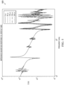
- FIG. 4 is an example frequency response, which shows the impedance magnitude response curve 400 for an example sensor assembly.
- the peak is a pole of the impedance magnitude response and the valley is a zero of the impedance magnitude response.
- the pole-zero pair represent a resonant frequency of the example sensor assembly. More specifically, the pole represents a parallel resonant frequency and the zero a series resonant frequency.
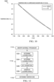
- FIG. 5 illustrates example impedance magnitude response curves 500 as a function of frequency for the example sensor assembly of FIG. 4 for different water droplet volumes ranging from 0 ⁇ L to 200 ⁇ L disposed in the center of the exposed surface of the example sensor assembly.
- a given resonant frequency will shift by different amounts based on the amount of water (or other contaminants) disposed on the exposed surface.
- the amount of frequency shift from the resonant frequency of the sensor assembly correlates to an amount of mass on the exposed surface.
- the contaminant detection subsystem 110 can be calibrated with the resonant frequencies and frequency responses of the sensor assembly and any and all likely contaminant mass levels that may come in contact with the exposed surface.
- This information can be stored in a database 180 and the comparator 118 compares the measured resonant frequencies and frequency responses with the stored resonant frequencies and frequency responses to determine the amount and/or type of contaminants on the exposed surface of the sensor assembly. Identification of the contaminants can be initialized at a first resonant frequency, a second resonant frequency, etc.
- the fault detection subsystem 130 performs system checks when the cleaning system 140 has not detected any appreciable mass on the exposed surface. System checks are performed by comparing a frequency response for a non-faulty, functional actuator and corresponding sensor assembly to a frequency response for a faulty, non-functional actuator and corresponding sensor assembly.
- FIG. 6 shows the impedance magnitude response for an example non-faulty, functioning (healthy) actuator and corresponding sensor assembly for different voltage excitation levels at around 300 kHz. The response has a zero between 285 and 295 kHz and a pole between 305 and 310 kHz, depending on the voltage excitation level.
- FIG. 6 shows the impedance magnitude response for an example non-faulty, functioning (healthy) actuator and corresponding sensor assembly for different voltage excitation levels at around 300 kHz. The response has a zero between 285 and 295 kHz and a pole between 305 and 310 kHz, depending on the voltage excitation level.
- the impedance magnitude response for an example faulty or damaged actuator and corresponding sensor assembly for different voltage excitation levels at around 300 kHz.
- the zero near 290 kHz no longer has a resonant effect when the voltage level increases to the required level to excite the actuator.
- the impedance magnitude response of the sensor assembly can be monitored periodically during the life of the actuator. If the response indicates that the resonant frequency is no longer present, then the actuator is faulty and the fault detection subsystem 130 disables a system start signal (described further hereinbelow).
- a faulty actuator that the fault detection subsystem 130 can detect by a frequency response is the de-polarization of the piezoelectric material in a piezoelectric transducer when the transducer overheats. This failure occurs when the temperature of the material exceeds its Curie temperature and occurs when too much current is driven thru the sensor assembly during the cleaning process. Other example failures may include a cracked or broken lens, transducer cracking, seal failure, epoxy failure, etc.
- the frequency response for the faulty actuator can be compared to the frequency response when the actuator is not faulty.
- the frequency response(s) for non-faulty actuators can be stored in a database 180 and accessed to compare the faulty actuator frequency responses to the non-faulty actuator frequency responses.
- the cleaning subsystem 140 initiates a cleaning process based on the identification of the contaminants by the contaminant detection subsystem 110.
- the cleaning subsystem 140 includes a cleaning mode selector 142, a cleaning phase selector 144, and a signal generation device 146.
- the cleaning mode selector 142 includes multiple cleaning modes (1, 2...N) and selects a cleaning mode based on the type of contaminant disposed on the exposed surface as determined by the contaminant detection subsystem 110 described hereinabove.
- a first cleaning mode may be implemented in response to determining the type of contaminants that correspond to mist
- a second cleaning mode may be implemented in response to determining the type of contaminants that correspond to water droplets
- a third cleaning mode may be implemented in response to determining the type of contaminants that correspond to ice, etc.
- Additional cleaning modes may correspond to other types of known (or unknown) types of contaminants such as dirt, mud, leaves, etc.
- the cleaning phase selector 144 selects a cleaning phase from multiple cleaning phases (A, B...N) within a given cleaning mode based on the amount (e.g., size, mass, weight, volume, etc.) of contaminant disposed on the exposed surface as determined by the contaminant detection subsystem 110 described hereinabove.
- each cleaning mode can include one or more different cleaning phases depending on the amount of contaminants.
- Each cleaning phase within a given cleaning mode can provide a different level, intensity or process of cleaning based on the amount of contaminants on the exposed surface.
- each cleaning phase can include one or more different parameters (i, ii...n) that define the cleaning process.
- the cleaning parameters can be defined as a frequency and/or voltage level that excites the actuator at specific resonant frequencies and/or amplitudes, which in turn vibrates the exposed surface thereby expelling contaminants from the exposed surface.
- Other parameters can include a time period (duration), heat drying, etc. Cleaning the exposed surface with ultrasonic systems and methods is disclosed in co-pending U.S. Pat. App. Serial No. 15/492,286, filed April 20, 2017 , entitled METHODS AND APPARATUS USING MULTISTAGE ULTRASONIC LENS CLEANING FOR IMPROVED WATER REMOVAL, and is herein incorporated by reference in its entirety.
- each cleaning phase can provide a different process of cleaning. For example, larger amounts of contaminants disposed on the exposed surface require a more aggressive cleaning than smaller amounts.
- the phase selector 144 selects the cleaning phase that includes an appropriate number of cleaning parameters to efficiently expel the water from the exposed surface. More specifically, a first parameter can correspond to a first (high) frequency (e.g., about 300kHz) that vibrates the actuator and hence, the exposed surface to atomize large water droplets.
- a second parameter can correspond to a second (lower) frequency (e.g., about 25kHz) that vibrates the actuator to further expel smaller water droplets.
- a third parameter can correspond to using the transducer as a heating device to heat dry the remaining water droplets.
- the cleaning phase and/or the cleaning parameter can change accordingly, (e.g., from a more aggressive cleaning process to a lesser aggressive cleaning process (or vice versa)) to efficiently remove the contaminant from the exposed surface.
- the voltage and/or frequency or any other parameter can vary during the cleaning process.
- the signal generation device 146 generates a cleaning control signal 148 to an actuator via an actuator interface 150.
- the cleaning control signal 148 drives the actuator or other cleaning parameter based on the selected cleaning phase and/or cleaning parameters.
- the cleaning signal may have a predetermined frequency and/or voltage level that drives the actuator at the resonant frequency and/or amplitude to efficiently expel or dissipate the contaminants from the exposed surface.
- the cleaning signal can dynamically change as the cleaning mode, the cleaning phase, and/or the cleaning parameters dynamically change. As the contaminants begin to dissipate from the exposed surface, the resonant frequency of the exposed surface including the remaining contaminants changes. Thus during dissipation, the resonant frequency is essentially constantly changing.
- the cleaning mode, the cleaning phase and/or the cleaning parameters can change to continue efficient dissipation of the contaminants from the exposed surface that corresponds to the changing resonant frequency.
- the cleaning signal can be initiated at a first resonant frequency, a second resonant frequency, etc.
- the temperature monitoring device 160 monitors a temperature of the actuator and can also serve as a power regulation device to regulate power to the actuator. Because the actuator is connected (e.g., mechanically coupled) to the exposed surface, the temperature monitoring device consequently monitors a temperature of the exposed surface. If the temperature of the actuator and/or exposed surface exceeds a threshold temperature the cleaning process is stopped until the actuator and/or exposed surface cools to ambient temperature or below the threshold temperature. Cooling can be passive cooling (e.g., air cool) or active cooling (e.g., air jets, water spray, etc.). In some examples, the temperature can be monitored by an external device, such as a thermocouple, infrared sensor, etc.
- the temperature can be monitored internally by the sensor assembly.
- the temperature monitoring device 160 can determine the temperature of the actuator and/or sensor assembly by measuring a frequency response of the sensor assembly for different temperatures.
- FIG. 8 illustrates an example impedance magnitude response 800 for an example sensor assembly at different temperatures.
- the magnitude of the impedance response at a particular frequency e.g. 20kHz
- This information can be stored and can be accessed to determine the temperature of the actuator and if the temperature of the transducer exceeds a temperature safety threshold. If so, the cleaning process is stopped until the actuator and/or exposed surface cools to a safe operating temperature, which is below the threshold temperature.
- FIG. 9 shows a close-up view of the impedance magnitude response 900 from 20 to 40 kHz.
- the temperature can easily be determined from the impedance data.
- FIG. 10 shows a plot 1000 that compares the temperate estimate using the linear equation and the actual temperature from the impedance magnitude plots.
- the maximum error in the estimated temperate is approximately 3.7°C.
- the controller 170 includes a microprocessor (microcontroller) 172 for executing instructions and/or algorithms to carry out the process of the sensing and signaling control/monitoring system 100.
- the microprocessor 172 can be embedded in a smart amplifier in a way such that the control system can be integrated into a single chip or can be comprised of multiple chips that are connected via bond wires.
- Logic control for the controller 170 can be software based (instructions executable by a processor core) or implemented as hardware, such as an arrangement of logic gates.
- the controller 170 may further include a data storage device 174 that may store data and/or instructions such as executable program code that is executed by the microprocessor 172.
- the data storage device 174 may store a number of applications and data that the microprocessor 172 can execute to implement at least the functionality described herein.
- the data storage device 174 may comprise various types of memory modules, including volatile and nonvolatile memory.
- the data storage device 174 can include one or more of random-access memory (RAM) 176, read-only memory (ROM) 178, flash solid state drive (SSD) (not shown), and a database 180.
- RAM random-access memory
- ROM read-only memory
- SSD flash solid state drive
- Additional devices and/or circuits 182 such as but not limited to pulse-width (PWM) switching controller(s), PWM pre-driver(s), amplifier(s), analog-to-digital convertor(s), multiplexor(s), etc. that facilitate execution of the signals regarding the actuator may be included.
- PWM pulse-width
- FIG. 11 is flow diagram 1100 illustrating an example method of expelling the foreign contaminants from the exposed surface of the sensor assembly.
- the process begins in the contaminant subsystem described hereinabove.
- the sensing and signaling control/monitoring system waits a period of time (e.g., waits for the system start signal) before beginning the process.
- the frequency measurement device monitors the resonant frequency to determine whether contaminant(s) are present on the exposed surface. If no material is detected, then at 1106, the process proceeds to the fault detection subsystem where the sensing and signaling control/monitoring system undergoes a system check.
- a decision is made to determine whether the sensor assembly or any other component is faulty. If the system is faulty, then at 1110, the cleaning process stops. If the system is not faulty, the process loops back to 1102 and the process starts again.
- the contaminant detection subsystem 110 If at 1104 material is detected, the contaminant detection subsystem 110 generates a material detection signal, then at 1112 the frequency response measurement circuit identifies the type of contaminant disposed on the exposed surface.
- the process proceeds to the cleaning subsystem and the cleaning process is performed, which is further described below with reference to FIG. 12 .
- the temperature of the actuator is measured.
- a decision is made to determine whether the temperature of the actuator exceeds a temperature threshold. If "YES,” the process proceeds to the temperature monitoring subsystem where at 1120, the cleaning process is disabled.
- cooling of the actuator and/or exposed surface is initialized.
- a decision is made to determine whether the actuator temperature still exceeds the temperature threshold. If “YES,” then at 1126 the cooling continues and the process loops back to 1124. If “NO,” then the process starts again at 1102.
- FIG. 12 is flow diagram illustrating an example cleaning process represented as 1114 in FIG. 11 .
- the cleaning mode is determined based on the type of contaminant disposed on the exposed surface, as described hereinabove.
- the cleaning phase is determined based on an amount of contaminants disposed on the exposed surface.
- the cleaning parameters are set based on the phase selection.
- the cleaning signal is generated to thereby initialize the cleaning process.
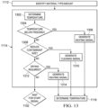
- FIG. 13 is a flow diagram illustrating another example cleaning process represented as 1114 in FIG. 11 .
- the contaminant identified on the exposed surface is ice and/or water.
- the temperature of the actuator is determined, which in turn determines the temperature of the exposed surface.
- a decision is made to determine whether the temperature is below freezing, which is an indication that ice has formed on the exposed surface. If "YES,” then a heating signal is generated to heat the exposed surface to thereby melt the ice. If "NO,” then at 1308 a decision is made to determine whether the amount of contaminant should be reduced.
- a cleaning signal is generated to excite the actuator at a resonant frequency of the exposed surface plus any contaminants on the exposed surface. If “NO,” then at 1312 a decision is made to determine whether drying is required based on the amount of contaminant. If “YES,” then at 1314 a heat signal is generated thereby heating the exposed surface of the sensor assembly. If “NO,” then the process loops back to 1102 and starts the process over again.
Landscapes
- Physics & Mathematics (AREA)
- General Physics & Mathematics (AREA)
- Biochemistry (AREA)
- General Health & Medical Sciences (AREA)
- Health & Medical Sciences (AREA)
- Life Sciences & Earth Sciences (AREA)
- Chemical & Material Sciences (AREA)
- Analytical Chemistry (AREA)
- Pathology (AREA)
- Immunology (AREA)
- Acoustics & Sound (AREA)
- Mechanical Engineering (AREA)
- Engineering & Computer Science (AREA)
- Optics & Photonics (AREA)
- Investigating Or Analyzing Materials By The Use Of Electric Means (AREA)
- Cleaning In General (AREA)
- Cleaning By Liquid Or Steam (AREA)
- Testing Or Calibration Of Command Recording Devices (AREA)
Abstract
Description
- This relates generally to a control system for a sensor assembly.
- Obstacle and collision avoidance systems are useful to mitigate damage to vehicles and other property due to collisions. Various technologies regarding obstacle and collision avoidance systems can be incorporated into vehicles at a reasonable cost. Some technologies include sensors and digital cameras for sensing and monitoring areas around the vehicle. In some cases, cameras can increase safety by being mounted in locations that can give drivers access to alternative perspectives, which are otherwise diminished or unavailable to the driver's usual view through windows or mirrors.
- One example includes a control system for a sensor that includes a contaminant detection subsystem that measures a resonant frequency of the sensor assembly, the sensor assembly including a housing, an actuator and a sensor both disposed in the housing, and a housing cover that enables sensing by the sensor therethrough, the contaminant detection subsystem detects contaminants on an exposed surface of the housing cover and provides a detection signal identifying contaminants on the housing cover based on the resonant frequency of the sensor assembly, and a cleaning subsystem that provides a cleaning control signal to the actuator to expel the contaminants from the housing cover in response to the detection signal.
- Another example includes a contaminant sensing system that includes a sensor assembly disposed on an exterior of a vehicle, the sensor assembly including an actuator and a sensor both disposed in a housing that enables sensing by the sensor through the housing, a contaminant detection subsystem that measures a resonant frequency of the sensor assembly, the contaminant detection subsystem to provide a detection signal in response to detecting contaminants on an exposed surface of the housing, a cleaning subsystem that implements expelling the contaminants from the exposed surface in response to the detection signal, and a temperature regulating device that regulates power to the actuator based on a temperature of the actuator.
- Another example includes a method of expelling contaminants from a sensor that includes measuring a change in a resonant frequency of a sensor assembly to detect contaminants on an exposed surface of the sensor assembly, measuring a change in the frequency response of the sensor assembly to determine the presence and amount of contaminants on the exposed surface, determining a cleaning mode based on the amount of contaminants on the exposed surface, determining a cleaning phase based on the amount of contaminants on the exposed surface, and generating a cleaning control signal to an actuator of the sensor assembly to expel the contaminants from the exposed surface.
The invention also covers the following: - 1. A control system for a sensor assembly, the system comprising:
- a contaminant detection subsystem to measure a resonant frequency of the sensor assembly, the sensor assembly including a housing, an actuator and a sensor both disposed in the housing, and a housing cover to enable sensing by the sensor therethrough, the contaminant detection subsystem being arranged to detect contaminants on an exposed surface of the housing cover and to provide a detection signal identifying contaminants on the housing cover based on the resonant frequency of the sensor assembly; and
- a cleaning subsystem to provide a cleaning control signal to the actuator to expel the contaminants from the housing cover in response to the detection signal.
- 2. The system of item 1, wherein the contaminant detection subsystem includes a frequency measurement circuit to measure a change in resonant frequency of the sensor assembly to determine presence or non-presence of the contaminants on the housing cover.
- 3. The system of
item 2, wherein the cleaning subsystem includes a cleaning mode selector to select a cleaning mode from a plurality of cleaning modes, based on the change in resonant frequency of the sensor assembly. - 4. The system of item 3, wherein each cleaning mode from the plurality of cleaning modes includes a cleaning phase selector to select a cleaning phase from a plurality of cleaning phases, based on the change in the frequency response of the sensor assembly.
- 5. The system of item 1, wherein the contaminant detection subsystem includes a frequency response measurement circuit to measure a change in the frequency response of the sensor assembly to determine a type of the contaminants and the amount of contaminants on the housing cover.
- 6. The system of
item 5, wherein the cleaning subsystem is coupled to provide the cleaning control signal to the actuator, depending on at least one of the type of contaminants and the amount of contaminants. - 7. The system of item 6, wherein the cleaning subsystem is coupled to provide the cleaning control signal to the actuator to adjust amplitude of vibration and excitation frequency, based on at least one of the type of the contaminants and the amount of contaminants.
- 8. The system of item 7, wherein the type and amount of contaminants are detected at a first resonant frequency, and the cleaning control signal is initiated at a second resonant frequency of the sensor assembly.
- 9. The system of
item 5 further comprising a fault detection device to detect faults in the sensor assembly based on the change in the frequency response of the sensor assembly at different voltage excitation levels to determine whether the resonant frequency of the sensor assembly is present at the different voltage excitation levels, to determine whether the sensor assembly is faulty, and to disable the system start signal if a fault is detected. - 10. The system of
item 5 further comprising a temperature regulating device to determine whether a temperature of the actuator exceeds a temperature threshold based on the change in the frequency response of the sensor assembly, and to disable the cleaning control signal and initiate a cooling procedure if the temperature of the actuator exceeds the temperature threshold. - 11. The system of item 1 further comprising a temperature regulating device to regulate a temperature of the contaminant detection subsystem and/or the sensor assembly, the contaminant detection subsystem being arranged to control the amplitude and frequency of vibration of the actuator depending on the temperature of the contaminant detection subsystem and the resonant frequency of the sensor assembly.
- 12. A contaminant sensing system, comprising:
- a sensor assembly disposed on an exterior of a vehicle, the sensor assembly including an actuator and a sensor both disposed in a housing to enable sensing by the sensor through the housing;
- a contaminant detection subsystem to measure a resonant frequency of the sensor assembly, the contaminant detection subsystem to provide a detection signal in response to detecting contaminants on an exposed surface of the housing;
- a cleaning subsystem to implement expelling the contaminants from the exposed surface in response to the detection signal; and
- a temperature regulating device to regulate power to the actuator based on a temperature of the actuator.
- 13. The system of item 12 further comprising a fault detection device to detect faults in the sensor assembly based on a change in the frequency response of the sensor assembly at different voltage excitation levels to determine whether the resonant frequency of the sensor assembly is present at the different voltage excitation levels, to determine whether the sensor assembly is faulty, and to disable the system start signal if a fault is detected.
- 14. The system of item 12, wherein the contaminant detection/identification subsystem includes a frequency measurement circuit to measure a change in the resonant frequency of the sensor assembly to determine a presence or non-presence of the contaminants on the exposed surface.
- 15. The system of item 12, wherein the contaminant detection/identification subsystem includes a frequency response measurement circuit to measure a change in frequency response of the sensor assembly to determine a type of the contaminants and the amount of contaminants disposed on the exposed surface.
- 16. The system of item 12, wherein the temperature regulating device is arranged to determine whether the actuator temperature exceeds a temperature threshold based on a change in the frequency response of the sensor assembly, and wherein the temperature regulating device is arranged to disable the cleaning process and initiate a cooling procedure if the actuator temperature exceeds the temperature threshold.
- 17. A method of expelling contaminants from a sensor, the method comprising:
- measuring a change in a resonant frequency of a sensor assembly to detect contaminants on an exposed surface of the sensor assembly;
- measuring a change in the frequency response of the sensor assembly to determine the presence and amount of contaminants on the exposed surface;
- determining a cleaning mode based on the amount of contaminants on the exposed surface;
- determining a cleaning phase based on the amount of contaminants on the exposed surface; and
- generating a cleaning control signal to an actuator of the sensor assembly to expel the contaminants from the exposed surface.
- 18. The method of item 17 further comprising vibrating the actuator at a resonant frequency of the sensor assembly to expel the contaminants from the exposed surface.
- 19. The method of item 17 further comprising determining whether a temperature of the actuator exceeds a temperature threshold based on the change in the frequency response of the sensor assembly, disabling the cleaning control signal if the temperature of the actuator exceeds the temperature threshold, and initiating a cooling procedure to cool the actuator.
- 20. The method of item 17 further comprising determining whether the actuator is faulty based on the change in the frequency response of the sensor assembly at different voltage levels and disabling a start signal if the actuator is faulty.
-
-
FIG. 1 illustrates an example sensing and signaling control/monitoring system for a sensor assembly. -
FIG. 2 illustrates an example for use on an exterior of a vehicle. -
FIG. 3 illustrates an example plot illustrating a normalized natural frequency versus normalized mass. -
FIG. 4 is an example impedance magnitude response curve for an example actuator. -
FIG. 5 illustrates example impedance magnitude response curves as a function of frequency for an example sensor assembly including different water droplet volumes disposed on the exposed surface of the example sensor assembly. -
FIG. 6 illustrates an impedance magnitude response curve for an example non-faulty actuator and corresponding sensor assembly for different voltage excitation levels at around 300 kHz. -
FIG. 7 illustrates an impedance magnitude response curve for an example faulty actuator and corresponding sensor assembly for different voltage excitation levels at around 300 kHz. -
FIG. 8 illustrates an example impedance magnitude response curve for an example piezoelectric transducer and housing cover used in a sensor assembly for different temperatures. -
FIG. 9 illustrates example impedance magnitude response curves for a frequency range of 20 to 40 kHz. -
FIG. 10 illustrates an example plot that compares a temperature estimate using a linear equation for an example actuator and actual temperature from the impedance magnitude response plots ofFIG. 9 . -
FIG. 11 is flow diagram illustrating an example method of expelling foreign contaminants from an exposed surface. -
FIG. 12 is flow diagram illustrating an example cleaning process. -
FIG. 13 is a flow diagram illustrating another example cleaning process. - This description relates generally to a sensing and signaling control/monitoring system for sensors (sensor assembly) disposed externally on a vehicle. More specifically, this description relates to a sensing and signaling control/monitoring system for identifying contaminants, cleaning, temperature detection/regulation, fault detection, power regulation, etc. relating to sensors disposed externally on the vehicle. Ultrasound excitation for cleaning sensors provides a more cost effective and efficient approach than water sprayers, mechanical wipers, or air jet solutions. Thus, the sensing and signaling control/monitoring system utilizes an actuator that vibrates the sensor assembly and consequently, drives a contaminant (e.g., water, mist, ice, dirt, mud, etc.) deposited on an exposed surface of a sensor assembly at its resonant frequency so as to facilitate the removal of the contaminant from the exposed surface. More specifically, when the actuator is excited by the proper periodic waveform, the actuator will vibrate the sensor assembly. Properly adjusting the frequency and amplitude of the vibration will expel the contaminant from the exposed surface. Because different contaminant amounts and types result in different resonant frequencies, the actuator can provide a frequency in a range of frequencies that encompass the resonant frequencies of the combined sensor assembly and the amount of contaminant deposited on the exposed surface. Some example actuators include a piezoelectric transducer, a voice coil actuator, etc.
- The sensing and signaling control/monitoring system can be utilized with any sensor device disposed externally on the vehicle. For example, some sensor devices include camera systems (e.g., camera monitoring systems (CMS), surround view systems (SVS)), photodetectors, external mirrors, reflectors, lasers (LiDAR). Other types of sensor devices may include short-range and long-range radar, near-field transceiver, acoustic sensors or the like. Accordingly, the housing for the lens of cameras or other devices can include an exposed lens cover surface (such as camera, reflector, sensor, etc.). Similarly, other types of sensors (different from optical sensors or cameras) also include an external housing to protect the sensing devices from the environment. Each housing has an associated surface through which the signaling and/or sensing are provided to implement the corresponding sensing function (imaging, radar, LiDAR, near-field sensing, etc.). The sensing and signaling control/monitoring system not only cleans the housing, as described hereinabove, but also includes components to monitor other environmental or operating parameters for the sensor assembly. Examples of the environmental and operating parameters include temperature detection, fault detection (e.g., monitor the integrity and functionality of the exposed surface), power regulation, etc. The sensing and signaling control/monitoring system thus can extend the mechanical life of the sensor assembly and maintain its surface substantially free of contaminants. The sensing and signaling control/monitoring system may also provide early warnings for potential failures for the sensor assembly.
-
FIG. 1 illustrates an example sensing and signaling control/monitoring system 100 andFIG. 2 is anexample sensor assembly 200 that can be used with the sensing and signaling control/monitoring system 100. The sensing and signaling control/monitoring system 100 includes acontaminant detection subsystem 110 that measures a resonant frequency of a sensor assembly, afault detection subsystem 130 that detects faults in the sensor assembly based on the change in the frequency of the sensor assembly, acleaning subsystem 140 that provides a cleaning control signal to an actuator in the sensor assembly to expel contaminants from exposed surfaces of the sensor assembly, and a temperature monitoring/power regulation device 160 that monitors a temperature of the actuator. Acontroller 170 is provided to control the subsystems and devices via abus 190. - The
example sensor assembly 200 illustrated inFIG. 2 is an example camera lens assembly for use on a camera. Thesensor assembly 200 includes ahousing 202 attached to acamera body 204, a sensing device (e.g., camera lens) 206 disposed in thehousing 202, atransparent housing cover 208 disposed at an open end of thehousing 202, and anactuator 210. Theactuator 210 is disposed in thehousing 202 and is attached to thehousing cover 208. Theactuator 210 includeselectrodes 212 that allow theactuator 210 to be connected to thecontroller 170 via acircuit interface 214. In the example camera lens assembly, theactuator 210 can be a transducer (e.g., piezoelectric cylindrical or ring type transducer) that when excited by proper signaling, will vibrate thehousing cover 208. As described herein, by correctly adjusting the frequency and/or the amplitude of the vibration the contaminants can be expelled from an exposedsurface 216 of thehousing cover 208. - Referring to
FIGS. 1 ,3 ,4 and5 , thecontaminant detection subsystem 110 detects and identifies contaminants disposed on an exposed surface of a sensor assembly (e.g., an exposed surface of a housing/lens cover) and can include atimer 112, afrequency measurement circuit 114, a frequencyresponse measuring circuit 116, and acomparator 118. In one example, thecontaminant detection subsystem 110 can be configured via thetimer 112 to periodically check for contaminants based on various factors such as an amount of time the vehicle is in motion, a speed of the vehicle, direction of the vehicle (e.g., forward, reverse, turning), etc. The wait period can be dynamically updated (i.e. increased, decreased, no change) during the detection process. In another example, thecontaminant detection subsystem 110 can be triggered manually (e.g., switch, push button, etc.) by an occupant of the vehicle. In yet another example, thecontaminant detection subsystem 110 can be triggered by the sensor assembly if the sensor assembly senses that contaminants may be on the exposed surface. Thus, the triggering of thecontaminant detection subsystem 110 can come from one of multiple sources. - Referring to
FIG. 1 , thefrequency measurement circuit 114 monitors a change in a resonant frequency of the sensor assembly to detect the presence of contaminants disposed on the exposed surface of the sensor assembly. A shift in the resonant frequency indicates that contaminants are present on the exposed surface of the sensor assembly. Specifically, the sensor assembly has a resonant frequency referred to as a natural frequency ω n and is defined by Equation (1):


-
FIG. 3 is anexample plot 300 that illustrates a change in the normalized natural frequency versus a change in the normalized mass, as described hereinabove. The change in normalized natural frequency is very sensitive to a small change in normalized mass. In the example inFIG. 3 , a change in normalized mass of about 10% results in a change in normalized natural frequency of about 70%. Thus, the sensitivity of the change in the resonant or natural frequency is effective in detecting the presence of contaminants on the exposed surface. Detection of the contaminants can be detected at a first resonant frequency, a second resonant frequency, etc. - Referring to
FIG. 1 , the frequencyresponse measurement circuit 116 measures a frequency response of the sensor assembly or any part thereof at a given resonant frequency to identify the type of contaminant and the amount of contaminant on the exposed surface. The frequency response of the sensor assembly plus the contaminants correlates to a specific amount of mass for contaminants on the exposed surface. For example,FIG. 4 is an example frequency response, which shows the impedancemagnitude response curve 400 for an example sensor assembly. The peak is a pole of the impedance magnitude response and the valley is a zero of the impedance magnitude response. The pole-zero pair represent a resonant frequency of the example sensor assembly. More specifically, the pole represents a parallel resonant frequency and the zero a series resonant frequency. The term parallel resonant frequency refers to a resonance between the parallel combination of the mechanical subsystem and the dielectric whereas the term series resonance frequency refers purely to a resonance of the mechanical subsystem.FIG. 5 illustrates example impedance magnitude response curves 500 as a function of frequency for the example sensor assembly ofFIG. 4 for different water droplet volumes ranging from 0µL to 200µL disposed in the center of the exposed surface of the example sensor assembly. - As illustrated in
FIG. 5 , a given resonant frequency will shift by different amounts based on the amount of water (or other contaminants) disposed on the exposed surface. The amount of frequency shift from the resonant frequency of the sensor assembly correlates to an amount of mass on the exposed surface. Thus, in order to identify the type and amount of the contaminant on the exposed surface, thecontaminant detection subsystem 110 can be calibrated with the resonant frequencies and frequency responses of the sensor assembly and any and all likely contaminant mass levels that may come in contact with the exposed surface. This information can be stored in adatabase 180 and thecomparator 118 compares the measured resonant frequencies and frequency responses with the stored resonant frequencies and frequency responses to determine the amount and/or type of contaminants on the exposed surface of the sensor assembly. Identification of the contaminants can be initialized at a first resonant frequency, a second resonant frequency, etc. - Referring to
FIGS. 1 ,6 and7 , thefault detection subsystem 130 performs system checks when thecleaning system 140 has not detected any appreciable mass on the exposed surface. System checks are performed by comparing a frequency response for a non-faulty, functional actuator and corresponding sensor assembly to a frequency response for a faulty, non-functional actuator and corresponding sensor assembly. For example,FIG. 6 shows the impedance magnitude response for an example non-faulty, functioning (healthy) actuator and corresponding sensor assembly for different voltage excitation levels at around 300 kHz. The response has a zero between 285 and 295 kHz and a pole between 305 and 310 kHz, depending on the voltage excitation level.FIG. 7 , on the other hand, shows the impedance magnitude response for an example faulty or damaged actuator and corresponding sensor assembly for different voltage excitation levels at around 300 kHz. In this case, the zero near 290 kHz no longer has a resonant effect when the voltage level increases to the required level to excite the actuator. As a result, the impedance magnitude response of the sensor assembly can be monitored periodically during the life of the actuator. If the response indicates that the resonant frequency is no longer present, then the actuator is faulty and thefault detection subsystem 130 disables a system start signal (described further hereinbelow). - One example of a faulty actuator that the
fault detection subsystem 130 can detect by a frequency response is the de-polarization of the piezoelectric material in a piezoelectric transducer when the transducer overheats. This failure occurs when the temperature of the material exceeds its Curie temperature and occurs when too much current is driven thru the sensor assembly during the cleaning process. Other example failures may include a cracked or broken lens, transducer cracking, seal failure, epoxy failure, etc. Thus, as described in the previous paragraph, the frequency response for the faulty actuator can be compared to the frequency response when the actuator is not faulty. The frequency response(s) for non-faulty actuators can be stored in adatabase 180 and accessed to compare the faulty actuator frequency responses to the non-faulty actuator frequency responses. - Referring again to
FIG. 1 , thecleaning subsystem 140 initiates a cleaning process based on the identification of the contaminants by thecontaminant detection subsystem 110. Thecleaning subsystem 140 includes acleaning mode selector 142, acleaning phase selector 144, and asignal generation device 146. The cleaningmode selector 142 includes multiple cleaning modes (1, 2...N) and selects a cleaning mode based on the type of contaminant disposed on the exposed surface as determined by thecontaminant detection subsystem 110 described hereinabove. For example, a first cleaning mode may be implemented in response to determining the type of contaminants that correspond to mist, a second cleaning mode may be implemented in response to determining the type of contaminants that correspond to water droplets, a third cleaning mode may be implemented in response to determining the type of contaminants that correspond to ice, etc. Additional cleaning modes may correspond to other types of known (or unknown) types of contaminants such as dirt, mud, leaves, etc. - The
cleaning phase selector 144 selects a cleaning phase from multiple cleaning phases (A, B...N) within a given cleaning mode based on the amount (e.g., size, mass, weight, volume, etc.) of contaminant disposed on the exposed surface as determined by thecontaminant detection subsystem 110 described hereinabove. Thus, each cleaning mode can include one or more different cleaning phases depending on the amount of contaminants. Each cleaning phase within a given cleaning mode can provide a different level, intensity or process of cleaning based on the amount of contaminants on the exposed surface. Specifically, each cleaning phase can include one or more different parameters (i, ii...n) that define the cleaning process. The cleaning parameters can be defined as a frequency and/or voltage level that excites the actuator at specific resonant frequencies and/or amplitudes, which in turn vibrates the exposed surface thereby expelling contaminants from the exposed surface. Other parameters can include a time period (duration), heat drying, etc. Cleaning the exposed surface with ultrasonic systems and methods is disclosed in co-pendingU.S. Pat. App. Serial No. 15/492,286, filed April 20, 2017 - As described hereinabove, each cleaning phase can provide a different process of cleaning. For example, larger amounts of contaminants disposed on the exposed surface require a more aggressive cleaning than smaller amounts. For example, if the cleaning
mode selector 142 selects a cleaning mode that corresponds to water, thephase selector 144 selects the cleaning phase that includes an appropriate number of cleaning parameters to efficiently expel the water from the exposed surface. More specifically, a first parameter can correspond to a first (high) frequency (e.g., about 300kHz) that vibrates the actuator and hence, the exposed surface to atomize large water droplets. A second parameter can correspond to a second (lower) frequency (e.g., about 25kHz) that vibrates the actuator to further expel smaller water droplets. A third parameter can correspond to using the transducer as a heating device to heat dry the remaining water droplets. Thus, during the cleaning process, as the amount of the contaminant on the exposed surface changes (decreases/increases), the cleaning phase and/or the cleaning parameter can change accordingly, (e.g., from a more aggressive cleaning process to a lesser aggressive cleaning process (or vice versa)) to efficiently remove the contaminant from the exposed surface. In other words, the voltage and/or frequency or any other parameter can vary during the cleaning process. - The
signal generation device 146 generates acleaning control signal 148 to an actuator via anactuator interface 150. Thecleaning control signal 148 drives the actuator or other cleaning parameter based on the selected cleaning phase and/or cleaning parameters. The cleaning signal may have a predetermined frequency and/or voltage level that drives the actuator at the resonant frequency and/or amplitude to efficiently expel or dissipate the contaminants from the exposed surface. The cleaning signal can dynamically change as the cleaning mode, the cleaning phase, and/or the cleaning parameters dynamically change. As the contaminants begin to dissipate from the exposed surface, the resonant frequency of the exposed surface including the remaining contaminants changes. Thus during dissipation, the resonant frequency is essentially constantly changing. Therefore, as the resonant frequency changes, the cleaning mode, the cleaning phase and/or the cleaning parameters can change to continue efficient dissipation of the contaminants from the exposed surface that corresponds to the changing resonant frequency. In addition, the cleaning signal can be initiated at a first resonant frequency, a second resonant frequency, etc. - Referring to
FIGS. 1 ,8 ,9 and10 , thetemperature monitoring device 160 monitors a temperature of the actuator and can also serve as a power regulation device to regulate power to the actuator. Because the actuator is connected (e.g., mechanically coupled) to the exposed surface, the temperature monitoring device consequently monitors a temperature of the exposed surface. If the temperature of the actuator and/or exposed surface exceeds a threshold temperature the cleaning process is stopped until the actuator and/or exposed surface cools to ambient temperature or below the threshold temperature. Cooling can be passive cooling (e.g., air cool) or active cooling (e.g., air jets, water spray, etc.). In some examples, the temperature can be monitored by an external device, such as a thermocouple, infrared sensor, etc. - In another example, the temperature can be monitored internally by the sensor assembly. For example, the
temperature monitoring device 160 can determine the temperature of the actuator and/or sensor assembly by measuring a frequency response of the sensor assembly for different temperatures.FIG. 8 illustrates an exampleimpedance magnitude response 800 for an example sensor assembly at different temperatures. The magnitude of the impedance response at a particular frequency (e.g. 20kHz) can be used to determine the temperature of the transducer. This information can be stored and can be accessed to determine the temperature of the actuator and if the temperature of the transducer exceeds a temperature safety threshold. If so, the cleaning process is stopped until the actuator and/or exposed surface cools to a safe operating temperature, which is below the threshold temperature. -
FIG. 9 shows a close-up view of theimpedance magnitude response 900 from 20 to 40 kHz. Given that the change in the impedance magnitude is uniform for a constant step changes in frequency, the temperature can easily be determined from the impedance data. In this example, the linear equation describing the temperature as a function of impedance magnitude for this example transducer is given by Equation (3):
-
FIG. 10 shows aplot 1000 that compares the temperate estimate using the linear equation and the actual temperature from the impedance magnitude plots. The maximum error in the estimated temperate is approximately 3.7°C. Thus, once an impedance magnitude value is known, the temperature of the actuator can be accurately estimated using a simple linear equation. - Referring again to
FIG. 1 , thecontroller 170 includes a microprocessor (microcontroller) 172 for executing instructions and/or algorithms to carry out the process of the sensing and signaling control/monitoring system 100. Themicroprocessor 172 can be embedded in a smart amplifier in a way such that the control system can be integrated into a single chip or can be comprised of multiple chips that are connected via bond wires. Logic control for thecontroller 170 can be software based (instructions executable by a processor core) or implemented as hardware, such as an arrangement of logic gates. - The
controller 170 may further include adata storage device 174 that may store data and/or instructions such as executable program code that is executed by themicroprocessor 172. Thedata storage device 174 may store a number of applications and data that themicroprocessor 172 can execute to implement at least the functionality described herein. Thedata storage device 174 may comprise various types of memory modules, including volatile and nonvolatile memory. For example, thedata storage device 174 can include one or more of random-access memory (RAM) 176, read-only memory (ROM) 178, flash solid state drive (SSD) (not shown), and adatabase 180. Additional devices and/orcircuits 182, such as but not limited to pulse-width (PWM) switching controller(s), PWM pre-driver(s), amplifier(s), analog-to-digital convertor(s), multiplexor(s), etc. that facilitate execution of the signals regarding the actuator may be included. -
FIG. 11 is flow diagram 1100 illustrating an example method of expelling the foreign contaminants from the exposed surface of the sensor assembly. The process begins in the contaminant subsystem described hereinabove. At 1102, the sensing and signaling control/monitoring system waits a period of time (e.g., waits for the system start signal) before beginning the process. At 1104, after the wait period has expired, the frequency measurement device monitors the resonant frequency to determine whether contaminant(s) are present on the exposed surface. If no material is detected, then at 1106, the process proceeds to the fault detection subsystem where the sensing and signaling control/monitoring system undergoes a system check. At 1108, a decision is made to determine whether the sensor assembly or any other component is faulty. If the system is faulty, then at 1110, the cleaning process stops. If the system is not faulty, the process loops back to 1102 and the process starts again. - If at 1104 material is detected, the
contaminant detection subsystem 110 generates a material detection signal, then at 1112 the frequency response measurement circuit identifies the type of contaminant disposed on the exposed surface. At 1114, the process proceeds to the cleaning subsystem and the cleaning process is performed, which is further described below with reference toFIG. 12 . At 1116, the temperature of the actuator is measured. At 1118, a decision is made to determine whether the temperature of the actuator exceeds a temperature threshold. If "YES," the process proceeds to the temperature monitoring subsystem where at 1120, the cleaning process is disabled. At 1122, cooling of the actuator and/or exposed surface is initialized. At 1124, a decision is made to determine whether the actuator temperature still exceeds the temperature threshold. If "YES," then at 1126 the cooling continues and the process loops back to 1124. If "NO," then the process starts again at 1102. - If at 1118 the actuator temperature does not exceed the temperature threshold, then at 1128, a decision is made to determine whether the cleaning process is complete. If "YES," then the process starts again at 1102. If "NO," then at 1130 the cleaning signal duration is updated and the process loops back to 1104.
-
FIG. 12 is flow diagram illustrating an example cleaning process represented as 1114 inFIG. 11 . At 1202, the cleaning mode is determined based on the type of contaminant disposed on the exposed surface, as described hereinabove. At 1204, the cleaning phase is determined based on an amount of contaminants disposed on the exposed surface. At 1206, the cleaning parameters are set based on the phase selection. At 1208, the cleaning signal is generated to thereby initialize the cleaning process. -
FIG. 13 is a flow diagram illustrating another example cleaning process represented as 1114 inFIG. 11 . Prior to this process, it was determined that the contaminant identified on the exposed surface is ice and/or water. At 1302, the temperature of the actuator is determined, which in turn determines the temperature of the exposed surface. At 1304, a decision is made to determine whether the temperature is below freezing, which is an indication that ice has formed on the exposed surface. If "YES," then a heating signal is generated to heat the exposed surface to thereby melt the ice. If "NO," then at 1308 a decision is made to determine whether the amount of contaminant should be reduced. If "YES," then at 1310 a cleaning signal is generated to excite the actuator at a resonant frequency of the exposed surface plus any contaminants on the exposed surface. If "NO," then at 1312 a decision is made to determine whether drying is required based on the amount of contaminant. If "YES," then at 1314 a heat signal is generated thereby heating the exposed surface of the sensor assembly. If "NO," then the process loops back to 1102 and starts the process over again. - Modifications are possible in the described embodiments, and other embodiments are possible, within the scope of the claims.
Claims (9)
- A method comprising:in response to measuring, by a frequency measurement circuit, a change in a resonant frequency of a sensor assembly to detect contaminants on a surface of the sensor assembly,measuring, by a frequency response measuring circuit, a change in a frequency response of the sensor assembly to determine a type and an amount of the contaminants on the surface;determining, by a cleaning mode selector, a cleaning mode based on the type of the contaminants on the surface and an amount of the contaminants on the surface, the cleaning mode comprises cleaning phases; andproviding, by a signal generation device, a cleaning control signal to an actuator of the sensor assembly based on the cleaning phases of the cleaning phases.
- The method of claim 1, further comprising selecting a cleaning phase of the cleaning phases.
- The method of claim 1, further comprising vibrating the actuator based on the cleaning control signal.
- The method of claim 1, further comprising in response to not detecting contaminants on the surface of the sensor assembly, determining whether the actuator has a fault based on the change in the frequency response of the sensor assembly at different voltage levels, and disabling the cleaning control signal responsive to the fault.
- The method of claim 1, further comprising:determining whether a temperature of the actuator exceeds a temperature threshold based on the change in the frequency response of the sensor assembly; anddisabling the cleaning control signal and initiating a cooling procedure to cool the actuator responsive to the temperature of the actuator exceeding the temperature threshold.
- The method of claim 1, wherein measuring the change in a frequency response of the sensor assembly is performed in response to detecting the contaminants on the surface of the sensor assembly.
- The method of claim 1, wherein the cleaning phase has a frequency and a voltage level.
- The method of claim 1, wherein the cleaning phases have corresponding frequencies and voltage levels.
- The method of claim 1, further comprising periodically measuring the change in the resonant frequency of a sensor assembly using a timer.
Applications Claiming Priority (4)
| Application Number | Priority Date | Filing Date | Title |
|---|---|---|---|
| US201762454154P | 2017-02-03 | 2017-02-03 | |
| US15/605,463 US10695805B2 (en) | 2017-02-03 | 2017-05-25 | Control system for a sensor assembly |
| EP18747814.4A EP3577451B1 (en) | 2017-02-03 | 2018-02-02 | Control system for a sensor assembly |
| PCT/US2018/016714 WO2018144924A1 (en) | 2017-02-03 | 2018-02-02 | Control system for a sensor assembly |
Related Parent Applications (1)
| Application Number | Title | Priority Date | Filing Date |
|---|---|---|---|
| EP18747814.4A Division EP3577451B1 (en) | 2017-02-03 | 2018-02-02 | Control system for a sensor assembly |
Publications (2)
| Publication Number | Publication Date |
|---|---|
| EP4535976A2 true EP4535976A2 (en) | 2025-04-09 |
| EP4535976A3 EP4535976A3 (en) | 2025-06-11 |
Family
ID=63038266
Family Applications (2)
| Application Number | Title | Priority Date | Filing Date |
|---|---|---|---|
| EP18747814.4A Active EP3577451B1 (en) | 2017-02-03 | 2018-02-02 | Control system for a sensor assembly |
| EP24218906.6A Pending EP4535976A3 (en) | 2017-02-03 | 2018-02-02 | Control system for a sensor assembly |
Family Applications Before (1)
| Application Number | Title | Priority Date | Filing Date |
|---|---|---|---|
| EP18747814.4A Active EP3577451B1 (en) | 2017-02-03 | 2018-02-02 | Control system for a sensor assembly |
Country Status (4)
| Country | Link |
|---|---|
| US (2) | US10695805B2 (en) |
| EP (2) | EP3577451B1 (en) |
| CN (1) | CN110234989B (en) |
| WO (1) | WO2018144924A1 (en) |
Families Citing this family (35)
| Publication number | Priority date | Publication date | Assignee | Title |
|---|---|---|---|---|
| US10596604B2 (en) | 2016-09-27 | 2020-03-24 | Texas Instruments Incorporated | Methods and apparatus using multistage ultrasonic lens cleaning for improved water removal |
| WO2018100796A1 (en) * | 2016-11-30 | 2018-06-07 | 株式会社村田製作所 | Vibration device, water droplet removal device for camera, and camera |
| EP3453459A1 (en) * | 2017-09-06 | 2019-03-13 | Siemens Aktiengesellschaft | Method for operating a plant, plant and computer program product |
| EP3668079B1 (en) * | 2017-12-27 | 2022-09-28 | Murata Manufacturing Co., Ltd. | Vibratory device and optical detection device |
| US20190210570A1 (en) * | 2018-01-08 | 2019-07-11 | Ford Global Technologies, Llc | Sensor cleaning and cooling |
| US10766464B2 (en) * | 2018-03-09 | 2020-09-08 | Ford Global Technologies, Llc | Sensor cleaning and thermal control |
| DE102018221868B4 (en) * | 2018-12-17 | 2022-09-08 | Volkswagen Aktiengesellschaft | Device and method for cooling at least one surface and/or at least one volume of a sensor of a vehicle |
| US10908132B2 (en) | 2019-01-07 | 2021-02-02 | Goodrich Corporation | Real-time performance and health monitoring of ice detector systems and estimation of remaining useful life |
| EP3715826B1 (en) * | 2019-03-26 | 2024-03-06 | Infineon Technologies AG | Sensor device, particle sensor device and method for detecting a particulate matter density |
| US11776460B2 (en) | 2019-03-29 | 2023-10-03 | Creeled, Inc. | Active control of light emitting diodes and light emitting diode displays |
| US11790831B2 (en) * | 2019-03-29 | 2023-10-17 | Creeled, Inc. | Active control of light emitting diodes and light emitting diode displays |
| US11694601B2 (en) | 2019-03-29 | 2023-07-04 | Creeled, Inc. | Active control of light emitting diodes and light emitting diode displays |
| US12198605B2 (en) | 2019-03-29 | 2025-01-14 | Creeled, Inc. | Active control of light emitting diodes and light emitting diode displays |
| US11727857B2 (en) | 2019-03-29 | 2023-08-15 | Creeled, Inc. | Active control of light emitting diodes and light emitting diode displays |
| US12142716B2 (en) | 2019-03-29 | 2024-11-12 | Creeled, Inc. | Active control of light emitting diodes and light emitting diode displays |
| FR3100998B1 (en) * | 2019-09-25 | 2022-06-03 | Lille Ecole Centrale | Device for cleaning a support covered with a liquid |
| DE102019128392A1 (en) * | 2019-10-21 | 2021-04-22 | Webasto SE | Roof module with environment sensor and sensor cover |
| CN110841996A (en) * | 2019-12-17 | 2020-02-28 | 北京万集科技股份有限公司 | Cleaning device, method, equipment and storage medium for lidar |
| US11695102B2 (en) | 2020-06-19 | 2023-07-04 | Creeled, Inc. | Active electrical elements with light-emitting diodes |
| CN113859177A (en) * | 2020-06-30 | 2021-12-31 | 图森有限公司 | Camera cleaning system for autonomous driving |
| DE102020128903B4 (en) | 2020-11-03 | 2023-11-09 | Marelli Automotive Lighting Reutlingen (Germany) GmbH | Sensor device, headlight, semi-autonomous motor vehicle and method |
| FR3117384B1 (en) * | 2020-12-14 | 2026-01-23 | Centrale Lille Inst | Device for cleaning an optical surface |
| FR3117385B1 (en) * | 2020-12-14 | 2024-06-28 | Univ Lille | Device for cleaning an optical surface |
| CN113687311B (en) * | 2021-09-01 | 2024-04-02 | 安徽城宜防务科技有限责任公司 | Radar device for dam monitoring |
| CA3250996A1 (en) | 2022-02-07 | 2023-08-10 | Creeled, Inc. | Light-emitting diodes with mixed clock domain signaling |
| US12014673B2 (en) | 2022-02-07 | 2024-06-18 | Creeled, Inc. | Light-emitting diodes with mixed clock domain signaling |
| CN115092095A (en) * | 2022-06-21 | 2022-09-23 | 珠海市魅族科技有限公司 | Sensor cleaning method, device, equipment and readable storage medium |
| CN115327973B (en) * | 2022-07-21 | 2023-10-27 | 阿波罗智能技术(北京)有限公司 | Cleaning device, equipment, electronic equipment and automatic driving vehicle |
| CN115468628A (en) * | 2022-07-22 | 2022-12-13 | 大庆飞海石油科技有限公司 | Liquid level meter with isolation protection structure for oil field |
| KR20240029443A (en) | 2022-08-26 | 2024-03-05 | 삼성전자주식회사 | Sensor device and method of operating the same |
| CN115815215A (en) * | 2022-11-08 | 2023-03-21 | 乳源东阳光智能科技有限公司 | Heating assembly, toilet bowl with heating assembly and cleaning method of heating assembly |
| CN116274166A (en) * | 2023-03-03 | 2023-06-23 | 首钢智新迁安电磁材料有限公司 | A cleaning method of anodic diaphragm and scanning electron microscope |
| US12014677B1 (en) | 2023-04-10 | 2024-06-18 | Creeled, Inc. | Light-emitting diode packages with transformation and shifting of pulse width modulation signals and related methods |
| US12526889B2 (en) | 2023-08-29 | 2026-01-13 | Creeled, Inc. | Light-emitting diode packages with varying current pulse width modulation and related methods |
| US12437707B2 (en) | 2023-09-27 | 2025-10-07 | Creeled, Inc. | Pseudo-exponential encoding for light-emitting devices and related methods |
Family Cites Families (75)
| Publication number | Priority date | Publication date | Assignee | Title |
|---|---|---|---|---|
| US3681626A (en) | 1971-11-11 | 1972-08-01 | Branson Instr | Oscillatory circuit for ultrasonic cleaning apparatus |
| SE436675B (en) | 1975-08-12 | 1985-01-14 | Ki Politekhnichsky I Im 50 Let | ELECTRIC ENGINE OPERATED BY PIEZOELECTRIC FORCES |
| JPS568688A (en) | 1979-07-05 | 1981-01-29 | Nisshin Flour Milling Co Ltd | Antitumor substance 1166a and its preparation |
| US4271371A (en) | 1979-09-26 | 1981-06-02 | Kabushiki Kaisha Morita Seisakusho | Driving system for an ultrasonic piezoelectric transducer |
| US4556467A (en) | 1981-06-22 | 1985-12-03 | Mineral Separation Corporation | Apparatus for ultrasonic processing of materials |
| DE3430605A1 (en) | 1984-08-20 | 1986-02-27 | Siemens AG, 1000 Berlin und 8000 München | METHOD AND DEVICE FOR CLEANING, DISINFECTING AND STERILIZING MEDICAL, IN PARTICULAR DENTAL, INSTRUMENTS |
| GB8421836D0 (en) | 1984-08-29 | 1984-10-03 | Smc Metal Tech Co Ltd | Contact lens cleaning apparatus |
| US4691725A (en) | 1985-05-13 | 1987-09-08 | Ultramed Corporation | Lens cleaner |
| US4852592A (en) | 1987-08-13 | 1989-08-01 | Digangi And Ross | Apparatus for the cleaning of contact lenses |
| JPH06103678B2 (en) | 1987-11-28 | 1994-12-14 | 株式会社東芝 | Semiconductor substrate processing method |
| US4836684A (en) | 1988-02-18 | 1989-06-06 | Ultrasonic Power Corporation | Ultrasonic cleaning apparatus with phase diversifier |
| JP2650303B2 (en) | 1988-02-25 | 1997-09-03 | アイシン精機株式会社 | Mirror cleaning equipment |
| US4870982A (en) | 1989-01-09 | 1989-10-03 | Tatung Company Of America, Inc. | Ultrasonic cleaning apparatus for household use |
| US5005015A (en) | 1989-08-07 | 1991-04-02 | General Electric Company | Ice detection system |
| US5113116A (en) | 1989-10-05 | 1992-05-12 | Firma J. Eberspacher | Circuit arrangement for accurately and effectively driving an ultrasonic transducer |
| US5178173A (en) | 1991-08-01 | 1993-01-12 | Robert J. Pace | Ultrasonic contact lens cleaning device |
| US5706840A (en) * | 1995-03-03 | 1998-01-13 | Sandia Corporation | Precision cleaning apparatus and method |
| US5853500A (en) * | 1997-07-18 | 1998-12-29 | Symetrix Corporation | Method for fabricating thin films of barium strontium titanate without exposure to oxygen at high temperatures |
| US6064259A (en) | 1998-07-24 | 2000-05-16 | Nikon Corporation Of America | High power, high performance pulse width modulation amplifier |
| GB9925373D0 (en) * | 1999-10-27 | 1999-12-29 | Schlumberger Ltd | Downhole instrumentation and cleaning system |
| US7215372B2 (en) * | 2002-05-17 | 2007-05-08 | Olympus Corporation | Optical apparatus having dust off function |
| US6607606B2 (en) | 2001-04-03 | 2003-08-19 | Hewlett-Packard Development Company, L.P. | Self-cleaning lens shield |
| DE20302419U1 (en) * | 2003-02-14 | 2003-04-24 | Schlosser, Stefan, 89264 Weißenhorn | Dirt detection system for greenhouse glass measures mechanical resonance |
| US7723899B2 (en) | 2004-02-03 | 2010-05-25 | S.C. Johnson & Son, Inc. | Active material and light emitting device |
| US7538473B2 (en) | 2004-02-03 | 2009-05-26 | S.C. Johnson & Son, Inc. | Drive circuits and methods for ultrasonic piezoelectric actuators |
| JP4585883B2 (en) | 2005-02-18 | 2010-11-24 | 株式会社東海理化電機製作所 | Power window device |
| US7742167B2 (en) | 2005-06-17 | 2010-06-22 | Perkinelmer Health Sciences, Inc. | Optical emission device with boost device |
| US20070003081A1 (en) | 2005-06-30 | 2007-01-04 | Insound Medical, Inc. | Moisture resistant microphone |
| US7799137B2 (en) * | 2005-07-15 | 2010-09-21 | Stokely-Van Camp, Inc. | Resonant frequency bottle sanitation |
| GB2435133A (en) * | 2006-02-08 | 2007-08-15 | Dyson Technology Ltd | Agitation source controller |
| US8136952B2 (en) | 2007-02-20 | 2012-03-20 | Canon Kabushiki Kaisha | Image capturing apparatus |
| US8137087B2 (en) | 2007-04-05 | 2012-03-20 | Ricoh Company, Ltd. | Toner preparation method and apparatus, and toner prepared thereby |
| US9070856B1 (en) | 2007-06-14 | 2015-06-30 | Misonix, Incorporated | Waveform generator for driving electromechanical device |
| JP4631921B2 (en) * | 2008-03-26 | 2011-02-16 | ソニー株式会社 | Piezoelectric element driving apparatus and piezoelectric element driving frequency control method |
| JP2009283069A (en) | 2008-05-22 | 2009-12-03 | Kenwood Corp | Optical disk device, cleaning method, and program |
| US7705517B1 (en) | 2008-10-30 | 2010-04-27 | Texas Instruments Incorporated | Ultrasound transmitter |
| US8854505B2 (en) | 2008-11-13 | 2014-10-07 | Nikon Corporation | Dust-removal optical device, a dust-removal imaging device, and method of manufacturing an optical device for removing dust |
| US8092691B2 (en) | 2009-03-09 | 2012-01-10 | Univenture, Inc. | Method and apparatus for separating particles from a liquid |
| US8293026B1 (en) | 2009-04-28 | 2012-10-23 | Integrated Medical Systems International, Inc. | Fixtures for the cleaning of lenses |
| EP2475186B1 (en) | 2009-09-04 | 2021-04-07 | Nitto Denko Corporation | Sound-transmitting film for microphone, sound-transmitting film member for microphone provided with the film, microphone, and electronic device provided with microphone |
| JP5056919B2 (en) | 2009-09-29 | 2012-10-24 | 株式会社デンソー | In-vehicle optical sensor cover and in-vehicle optical sensor device |
| JP5530327B2 (en) | 2010-10-06 | 2014-06-25 | 中村科学工業株式会社 | How to remove moisture from plastic materials |
| JP5725882B2 (en) | 2011-01-25 | 2015-05-27 | キヤノン株式会社 | Foreign object removal unit and optical apparatus provided with the same |
| US9171535B2 (en) | 2011-03-03 | 2015-10-27 | Nitto Denko Corporation | Waterproof sound-transmitting membrane and electrical product |
| JP5693310B2 (en) * | 2011-03-17 | 2015-04-01 | キヤノン株式会社 | Foreign matter removing apparatus and optical apparatus including the same |
| WO2012129521A1 (en) | 2011-03-23 | 2012-09-27 | Gentex Corporation | Lens cleaning apparatus |
| EP2744607B1 (en) | 2011-10-20 | 2018-12-12 | Canon Kabushiki Kaisha | Dust removing device and imaging device |
| KR20130076250A (en) | 2011-12-28 | 2013-07-08 | 삼성전자주식회사 | Electronic apparatus with resonance structure for speaker |
| US9796359B2 (en) * | 2012-02-23 | 2017-10-24 | The Raymond Corporation | Method and apparatus for removing and preventing lens surface contamination on a vehicle lens |
| KR20130104138A (en) | 2012-03-13 | 2013-09-25 | 삼성전자주식회사 | Waterproof case for portable terminal |
| JP5885552B2 (en) * | 2012-03-21 | 2016-03-15 | キヤノン株式会社 | Vibration device, drive device having the vibration device, and optical apparatus |
| BR112015000243B1 (en) | 2012-07-11 | 2021-07-13 | Nissan Motor Co., Ltd | CLEANING DEVICE FOR VEHICLE MOUNTED CAMERA AND METHOD OF CLEANING VEHICLE MOUNTED CAMERA |
| US9436005B2 (en) | 2012-08-02 | 2016-09-06 | Gentex Corporation | Amplified piezoelectric camera lens cleaner |
| US9084053B2 (en) | 2013-01-11 | 2015-07-14 | Red Tail Hawk Corporation | Microphone environmental protection device |
| TWM456008U (en) | 2013-02-01 | 2013-06-21 | Cho-Yi Lin | Electronic device and dust cap thereof |
| US9335355B2 (en) | 2013-03-06 | 2016-05-10 | Apple Inc. | Electronic device with liquid contact sensors |
| US9519021B2 (en) | 2013-03-11 | 2016-12-13 | Covidien Lp | Systems and methods for detecting abnormalities within a circuit of an electrosurgical generator |
| CN103191886B (en) * | 2013-03-21 | 2015-04-08 | 安徽师范大学 | Method for detecting surface pollution degree through ultrasonic wave and cleaning pollution |
| US9880061B2 (en) * | 2013-06-14 | 2018-01-30 | Hrl Laboratories, Llc | Methods and apparatus for sensing the internal temperature of an electrochemical device |
| US9568727B2 (en) | 2014-03-25 | 2017-02-14 | Amazon Technologies, Inc. | Electrowetting display pixel architecture |
| US9226076B2 (en) | 2014-04-30 | 2015-12-29 | Apple Inc. | Evacuation of liquid from acoustic space |
| US9573165B2 (en) | 2014-08-22 | 2017-02-21 | Apple Inc. | Hydrophobic mesh cover |
| US10663386B2 (en) * | 2014-12-19 | 2020-05-26 | Micro Motion, Inc. | Controlling a vibration of a vibratory sensor based on a phase error |
| US10401618B2 (en) | 2015-03-11 | 2019-09-03 | Texas Instruments Incorporated | Ultrasonic lens cleaning system with current sensing |
| KR101851435B1 (en) | 2015-12-07 | 2018-04-23 | 명지대학교 산학협력단 | Apparatus and method for cleaning lesns part of cameras |
| DE112016004551T5 (en) | 2015-12-24 | 2018-07-12 | Murata Manufacturing Co., Ltd. | SWINGING DEVICE, METHOD FOR CONTROLLING THE SAME AND CAMERA |
| EP3460460B1 (en) | 2016-05-18 | 2024-02-28 | Myongji University Industry and Academia Cooperation Foundation | Cleaning apparatus and method |
| US10071400B2 (en) | 2016-06-20 | 2018-09-11 | Texas Instruments Incorporated | Ultrasonic lens cleaning with travelling wave excitation |
| US10596604B2 (en) | 2016-09-27 | 2020-03-24 | Texas Instruments Incorporated | Methods and apparatus using multistage ultrasonic lens cleaning for improved water removal |
| US10682675B2 (en) | 2016-11-01 | 2020-06-16 | Texas Instruments Incorporated | Ultrasonic lens cleaning system with impedance monitoring to detect faults or degradation |
| WO2018169233A1 (en) | 2017-03-14 | 2018-09-20 | Lg Electronics Inc. | Device for cleaning surface using electrowetting element and method for controlling the same |
| US10780467B2 (en) | 2017-04-20 | 2020-09-22 | Texas Instruments Incorporated | Methods and apparatus for surface wetting control |
| US11607704B2 (en) | 2017-04-20 | 2023-03-21 | Texas Instruments Incorporated | Methods and apparatus for electrostatic control of expelled material for lens cleaners |
| US10908414B2 (en) | 2017-05-10 | 2021-02-02 | Texas Instruments Incorporated | Lens cleaning via electrowetting |
| US10527843B2 (en) | 2017-05-12 | 2020-01-07 | International Business Machines Corporation | Ultra-sonic self-cleaning system |
-
2017
- 2017-05-25 US US15/605,463 patent/US10695805B2/en active Active
-
2018
- 2018-02-02 WO PCT/US2018/016714 patent/WO2018144924A1/en not_active Ceased
- 2018-02-02 EP EP18747814.4A patent/EP3577451B1/en active Active
- 2018-02-02 EP EP24218906.6A patent/EP4535976A3/en active Pending
- 2018-02-02 CN CN201880009347.9A patent/CN110234989B/en active Active
-
2020
- 2020-06-29 US US16/915,704 patent/US20200324324A1/en not_active Abandoned
Also Published As
| Publication number | Publication date |
|---|---|
| EP3577451A1 (en) | 2019-12-11 |
| US20200324324A1 (en) | 2020-10-15 |
| EP3577451A4 (en) | 2020-07-29 |
| US10695805B2 (en) | 2020-06-30 |
| WO2018144924A1 (en) | 2018-08-09 |
| EP3577451B1 (en) | 2024-12-18 |
| EP4535976A3 (en) | 2025-06-11 |
| CN110234989A (en) | 2019-09-13 |
| CN110234989B (en) | 2023-01-03 |
| US20180221921A1 (en) | 2018-08-09 |
Similar Documents
| Publication | Publication Date | Title |
|---|---|---|
| EP3577451B1 (en) | Control system for a sensor assembly | |
| US11467396B2 (en) | Cleaning device, and image capturing apparatus including cleaning device | |
| US11366076B2 (en) | Transducer temperature sensing | |
| US10682675B2 (en) | Ultrasonic lens cleaning system with impedance monitoring to detect faults or degradation | |
| US11042026B2 (en) | Transducer-induced heating and cleaning | |
| US11979669B2 (en) | Cleaning device, imaging unit including the same, and cleaning method | |
| US11420238B2 (en) | Transducer-induced heating-facilitated cleaning | |
| CN102574281A (en) | Protective sensor system for a hand-held power tool | |
| CN105308476B (en) | Ultrasound-based measuring transducer and method for operating an ultrasound-based measuring transducer | |
| US20210015516A1 (en) | Medical device system, abnormality determination method, and computer-readable recording medium | |
| US20200282435A1 (en) | Ultrasonic lens cleaning systems and methods | |
| US20250281948A1 (en) | Method for Detecting Dirt and Cleaning with Piezo Transducer, Device, Automotive Part and Vehicle | |
| JP7548408B2 (en) | Object Detection System | |
| JP2009501505A (en) | Apparatus for drive control of electromagnetic actuator and first inductance inspection method of electromagnetic actuator | |
| JP7722551B2 (en) | Vibration device and vibration method | |
| WO2023188516A1 (en) | Control device for controlling vibration device and method for controlling vibration device | |
| WO2015142644A2 (en) | Detection and correction of window moisture condensation | |
| JPH078125U (en) | Water droplet removal control device |
Legal Events
| Date | Code | Title | Description |
|---|---|---|---|
| PUAI | Public reference made under article 153(3) epc to a published international application that has entered the european phase |
Free format text: ORIGINAL CODE: 0009012 |
|
| STAA | Information on the status of an ep patent application or granted ep patent |
Free format text: STATUS: THE APPLICATION HAS BEEN PUBLISHED |
|
| AC | Divisional application: reference to earlier application |
Ref document number: 3577451 Country of ref document: EP Kind code of ref document: P |
|
| AK | Designated contracting states |
Kind code of ref document: A2 Designated state(s): AL AT BE BG CH CY CZ DE DK EE ES FI FR GB GR HR HU IE IS IT LI LT LU LV MC MK MT NL NO PL PT RO RS SE SI SK SM TR |
|
| REG | Reference to a national code |
Ref country code: DE Ref legal event code: R079 Free format text: PREVIOUS MAIN CLASS: H10N0030800000 Ipc: G01N0029120000 |
|
| PUAL | Search report despatched |
Free format text: ORIGINAL CODE: 0009013 |
|
| AK | Designated contracting states |
Kind code of ref document: A3 Designated state(s): AL AT BE BG CH CY CZ DE DK EE ES FI FR GB GR HR HU IE IS IT LI LT LU LV MC MK MT NL NO PL PT RO RS SE SI SK SM TR |
|
| RIC1 | Information provided on ipc code assigned before grant |
Ipc: H10N 30/80 20230101ALI20250502BHEP Ipc: G02B 27/00 20060101ALI20250502BHEP Ipc: G01N 29/036 20060101ALI20250502BHEP Ipc: B60S 1/56 20060101ALI20250502BHEP Ipc: G01N 29/02 20060101ALI20250502BHEP Ipc: B06B 1/06 20060101ALI20250502BHEP Ipc: B08B 7/02 20060101ALI20250502BHEP Ipc: G01D 3/00 20060101ALI20250502BHEP Ipc: G01N 29/12 20060101AFI20250502BHEP |
|
| STAA | Information on the status of an ep patent application or granted ep patent |
Free format text: STATUS: REQUEST FOR EXAMINATION WAS MADE |
|
| 17P | Request for examination filed |
Effective date: 20251211 |
|
| STAA | Information on the status of an ep patent application or granted ep patent |
Free format text: STATUS: EXAMINATION IS IN PROGRESS |
|
| 17Q | First examination report despatched |
Effective date: 20260323 |