EP4535943A2 - Hochdichtes stromverteilungssystem mit integrierter sammelschiene, intelligenter abzweigdose und kompakten rack-stromverteilungseinheiten - Google Patents
Hochdichtes stromverteilungssystem mit integrierter sammelschiene, intelligenter abzweigdose und kompakten rack-stromverteilungseinheiten Download PDFInfo
- Publication number
- EP4535943A2 EP4535943A2 EP24201495.9A EP24201495A EP4535943A2 EP 4535943 A2 EP4535943 A2 EP 4535943A2 EP 24201495 A EP24201495 A EP 24201495A EP 4535943 A2 EP4535943 A2 EP 4535943A2
- Authority
- EP
- European Patent Office
- Prior art keywords
- power
- conductors
- ocp
- rack
- distribution system
- Prior art date
- Legal status (The legal status is an assumption and is not a legal conclusion. Google has not performed a legal analysis and makes no representation as to the accuracy of the status listed.)
- Pending
Links
Images




Classifications
-
- H—ELECTRICITY
- H05—ELECTRIC TECHNIQUES NOT OTHERWISE PROVIDED FOR
- H05K—PRINTED CIRCUITS; CASINGS OR CONSTRUCTIONAL DETAILS OF ELECTRIC APPARATUS; MANUFACTURE OF ASSEMBLAGES OF ELECTRICAL COMPONENTS
- H05K7/00—Constructional details common to different types of electric apparatus
- H05K7/14—Mounting supporting structure in casing or on frame or rack
- H05K7/1485—Servers; Data center rooms, e.g. 19-inch computer racks
- H05K7/1488—Cabinets therefor, e.g. chassis or racks or mechanical interfaces between blades and support structures
- H05K7/1492—Cabinets therefor, e.g. chassis or racks or mechanical interfaces between blades and support structures having electrical distribution arrangements, e.g. power supply or data communications
-
- H—ELECTRICITY
- H02—GENERATION; CONVERSION OR DISTRIBUTION OF ELECTRIC POWER
- H02B—BOARDS, SUBSTATIONS OR SWITCHING ARRANGEMENTS FOR THE SUPPLY OR DISTRIBUTION OF ELECTRIC POWER
- H02B1/00—Frameworks, boards, panels, desks, casings; Details of substations or switching arrangements
- H02B1/20—Bus-bar or other wiring layouts, e.g. in cubicles, in switchyards
Definitions
- the present disclosure is directed generally to the field of power distribution, and more particularly to devices and components for power distribution.
- the power distribution system includes a rack power distribution unit (PDU, rPDU) mountable in the server cabinet and including a linear array of outlet power sockets (e.g., 3N sockets, one for each outlet power circuit).
- a set of 3N conductors e.g., cables; one conductor for each outlet power circuit
- connects the smart TOB device e.g., by a TOB connecting device
- the rPDU e.g., via a rack connecting device
- the array of outlet power sockets is a vertical stack.
- the set of OCP devices include mixed OCP devices corresponding to a third subset of the 3N outlet power circuits and to their corresponding mixed-amperage sockets, the set of mixed OCP devices including OCP devices associated with the first and the at least one second amperage level.
- the rack connecting device includes a set of conductors (e.g., corresponding to the 3N single-phase output circuits or to a subset thereof), each conductor terminating in a conductor terminal that plugs into a rack-side connector of the rack connecting device (e.g., and supplies output power to the rPDU via the rack connecting device).
- the conductor terminals and/or rack-side connectors indicate the conductors by phase and/or amperage level (e.g., low amperage, high amperage, mixed amperage).
- conductor terminals indicative of or corresponding to a particular amperage level are incompatible with rack-side connectors indicative of or corresponding to other amperage levels.
- the smart TOB includes a monitoring system for collecting power data associated with the three-phase input power supply. Further, the smart TOB includes a communications portal for providing collected power data to a remotely located user, or for receiving control input from the remotely located user.
- the power data includes an amperage and/or a voltage of the three-phase input power supply.
- the power data includes an instantaneous power level and/or a cumulative power level of the three-phase input power supply.
- the power data includes circuit power data for one or more monitored single-phase output power circuits based on the input power supply.
- the circuit power data includes an amperage and/or a voltage of one or more single-phase output power circuits.
- the smart TOB monitoring system includes a monitor display on an external surface or face of the smart TOB, the monitor display capable of presenting collected power data to a user.
- the plurality of conductors includes one or more meshed conductors, e.g., a subset of conductors disposed within a meshed sleeve.
- the incorporation of OCP devices within the TOB may eliminate the use of multiple-socket OCP devices as implemented by the legacy power outlet device 125. Further, single-socket OCP devices incorporated within the TOB may allow the use of next-generation socket/outlet implementations at higher amperage ratings. For example, a next-generation AI/ML server may require a 2800 W power supply (e.g., drawing c. 11.66 A at 240 V assuming unity power factor).
- the TOB may be configured to accommodate OCP devices rated higher than 20 A.
- OCP devices rated higher than 20 A For example, next-generation socket styles manufactured by Anderson Power, BizLink, etc. may be rated for 30A or higher via a relatively small form factor socket (e.g., comparable with C13/C19 legacy sockets 145).
- Examples of the TOB may combine conventional 20 A OCP devices with 30 A or higher OCP devices, allowing the rPDU to incorporate higher-amperage or mixed-amperage sockets as well as conventional C13/C19 sockets 145.
- each single-phase output power circuit may require a conductor (280a) for carrying the output power to the rPDU 215 and a neutral wire (280b) for returning the circuit to the TOB 205; accordingly, a set of 3N single-phase output power circuits may include a total of 6N conductors 280.
- the set of conductors 280 may be implemented as one or more meshed conductors, e.g., wherein a set of individually insulated conductors are combined within a meshed sleeve, eliminating the need for significant derating associated with the carriage of the unresolved three-phase input power supply 140.
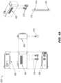
- the communications ports 405 of the smart TOB 205 may include a network port for connecting the smart TOB to local and/or external networks.
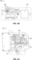
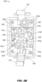
- the smart TOB 205 may include a monitoring card 410 incorporating voltage touchpoints and/or current sensing components (e.g., current transducers) for voltage/amperage monitoring of the input power supply (140, FIG. 1 ) and/or single-phase output power circuits 235a-235n, 240a-240n, 245a-245n as discussed above.
- the smart TOB 205 may incorporate OCP devices 400 and current transformers 415.
- the conductor terminals 510a-510l may be plugged into or otherwise engaged with the rack-side connectors 505a-505l to supply power (via the single-phase output power circuits 235a-235n, 240a-240n, 245a-245n) to the rPDU 215 (e.g., and to each socket (285a-285n, 290a-290n, 295a-295n; FIGS. 2A-B ) of the rPDU).
- the rack connector device 210 may include tabs 515 and pins 520 compatible with the rPDU 215, the tabs 515 and pins 520 securable to provide additional security and stability for the plugged-in/engaged conductor terminals 510a-510l.
- the rack-side connectors 505a-505l and conductor terminals 510a-510l may be physically keyed to clearly indicate amperage levels (e.g., or other relevant circuit information) for the single-phase output power circuits 235a-235n, 240a-240n, 245a-245n.
- amperage levels e.g., or other relevant circuit information
- the three-phase input power supply 140, FIG. 2A
- the smart TOB 205, FIG.
- the three-phase input power supply 140 may be resolved into single-phase output circuits at other amperage levels if desired or needed.
- physical keying of rack-side connectors 505a-505l and conductor terminals 510a-505l may prevent the inadvertent connection to sockets (285a-285n, 290a-290n, 295a-295n) of single-phase output power circuits 235a-235n, 240a-240n, 245a-245n and/or OCP devices (400, FIG. 4A ) whose higher amperage levels the sockets may not be configured to handle.
- eliminating inadvertent connections may therefore significantly reduce the risk of fire or electrical damage to the power distribution system 200 and/or any server or computer equipment (135, FIG. 1 ) connected or proximate thereto.
- rack-side connectors 505a-505l and conductor terminals 510a-505l may be keyed to indicate an associated amperage level collectively, e.g., with respect to a set of single-phase output power circuits 235a-235n, 240a-240n, 245a-245n and their corresponding OCP devices 400, or individually, e.g., with respect to a particular output power circuit, a particular conductor or set thereof, and a particular OCP device or set thereof.
- the set of rack-side connectors 505a-505l may be divided into two sets (upper 525, lower 530) of six rack-side connectors, wherein each set 525, 530 includes three rack-side connectors 505a-505c, 505g-505i for carrying a single-phase output power circuit 235a-235n, 240a-240n, 245a-245n and three rack-side connectors 505d-505f, 505j-505l for counterpart neutral cables (280b, FIG. 2B ).
- the use of one or more tabbed rack-side connectors 505a, 505c, 505g, 505i may indicate the associated set of three single-phase output power circuits 235a-235n, 240a-240n, 245a-245n as mixed-amperage or high-amperage.
- a set of three round rack-side connectors 505b, 505h may indicate a corresponding set of all low-amperage (e.g., 20 A) single-phase output power circuits.
- the three single-phase output power circuits associated with the rack-side connectors 505a-505c, 505g-505i may be keyed to indicate mixed-amperage or high-amperage circuits based on the number of tabbed connectors (e.g., one tabbed connector to indicate a mixed-amperage set, two tabbed connectors to indicate a high-amperage set) or via the alignment of each tab 535 relative to its rack-side connector.
- the tabs 535 of the rack-side connectors 505a, 505g are aligned at a substantially 45-degree angle to the vertical, or between the 10:00 and 11:00 positions, whereas the tabs of the rack-side connectors 505c, 505i are aligned closer to vertical, e.g., nearer the 11:00 position.
- the corresponding set of rack-side connectors e.g., connectors 505a/505g having a tab between 10:00 and 11:00, connectors 505b/505h having no tab, connectors 505c/505i having a tab at 11:00
- any tabbed conductor connectors 510a, 510c, 510g, 510i used in whole or in part to indicate a mixed-amperage or high-amperage set of circuits is incompatible with, and cannot be plugged into, a set of tabless rack-side connectors 505d-505f, 505j-505l
- the use of tabs 535 to indicate higher amperages may prevent the inadvertent insertion of tabbed conductor connectors 510a, 510c, 510g, 510i into tabless rack-side connectors 505d-505f, 505j-505l (and accordingly the inadvertent connection of higher-amperage single-phase output circuits
- connector keying may be used to indicate amperage level individually, rather than applied to a set of single-phase output power circuits.
- the presence and/or alignment of tabs 535 relative to a rack-side connector 505a-505l and/or a conductor connector 510a-510l may be used to individually key or indicate the amperage level of the single-phase output power circuit corresponding to a particular combination of rack-side connector and conductor connector.
- connector keying of the rack connector device 210 as shown by FIGS. 5A and 5B may likewise be applied by the TOB connector device (270, FIG. 2B ).
- Examples of low-amperage rPDUs 215a-215c, high-amperage rPDU 215d, and mixed-amperage rPDU 215e are shown.
- the low-amperage rPDU 215a may include six C19 sockets 540, each rated at 20 A.
- the low-amperage rPDU 215b may include six hybrid C13/C19 sockets 545 (e.g., compatible with either C13 or C19 connections) and three C19 sockets 540, each rated at 20 A.
- the low-amperage rPDU 215c may include twelve hybrid C13/C19 sockets 545.
- the high-amperage rPDU 215d may include six 30 A sockets 550.
- the mixed-amperage rPDU 215e may include six hybrid C13/C19 sockets 545 (rated at 20 A) and three 30 A sockets 550.
- examples of the inventive concepts disclosed herein may have numerous advantages.
- examples of the power distribution system disclosed herein may more effectively serve the needs of next-generation energy-intensive artificial intelligence/machine learning (AI/ML) applications (e.g., large language models (LLM), generative Al) while similarly accommodating next-generation direct-to-chip (D2C) cooling schemes by preserving rear-rack/rear-cabinet hygiene and airspace.
- AI/ML artificial intelligence/machine learning
- LLM large language models
- D2C next-generation direct-to-chip
- the power distribution system is configured for safe implementation and management of higher-amperage and mixed-amperage power supplies and circuits, resolving three-phase input power above, rather than in, the rackspace and providing for clear identification of conductors by amperage level/s. In this way, inadvertent connection of lower-amperage outlets to higher-amperage OCP devices may be prevented.
- smart tap-off boxed "smart" TOB may provide detailed monitoring of the power supply, sharing of comprehensive monitoring data across the network to prevent duplicative monitoring, and remote adjustments to overcurrent protection and/or individual outlets (e.g., activation/deactivation).
- an implementer may opt for a mainly hardware and/or firmware vehicle; alternatively, if flexibility is paramount, the implementer may opt for a mainly software implementation; or, yet again alternatively, the implementer may opt for some combination of hardware, software, and/or firmware.
- any vehicle to be utilized is a choice dependent upon the context in which the vehicle will be deployed and the specific concerns (e.g., speed, flexibility, or predictability) of the implementer, any of which may vary.
- Those skilled in the art will recognize that optical aspects of implementations will typically employ optically-oriented hardware, software, and or firmware.
- a signal bearing medium examples include, but are not limited to, the following: a recordable type medium such as a floppy disk, a hard disk drive, a Compact Disc (CD), a Digital Video Disk (DVD), a digital tape, a computer memory, etc.; and a transmission type medium such as a digital and/or an analog communication medium (e.g., a fiber optic cable, a waveguide, a wired communications link, a wireless communication link, etc.).
- electrical circuitry includes, but is not limited to, electrical circuitry having at least one discrete electrical circuit, electrical circuitry having at least one integrated circuit, electrical circuitry having at least one application specific integrated circuit, electrical circuitry forming a general purpose computing device configured by a computer program (e.g., a general purpose computer configured by a computer program which at least partially carries out processes and/or devices described herein, or a microprocessor configured by a computer program which at least partially carries out processes and/or devices described herein), electrical circuitry forming a memory device (e.g., forms of random access memory), and/or electrical circuitry forming a communications device (e.g., a modem, communications switch, or optical-electrical equipment).
- a computer program e.g., a general purpose computer configured by a computer program which at least partially carries out processes and/or devices described herein, or a microprocessor configured by a computer program which at least partially carries out processes and/or devices described herein
- electrical circuitry forming a memory device
- a typical data processing system generally includes one or more of a system unit housing, a video display device, a memory such as volatile and non-volatile memory, processors such as microprocessors and digital signal processors, computational entities such as operating systems, drivers, graphical user interfaces, and applications programs, one or more interaction devices, such as a touch pad or screen, and/or control systems including feedback loops and control motors (e.g., feedback for sensing position and/or velocity; control motors for moving and/or adjusting components and/or quantities).
- a typical data processing system may be implemented utilizing any suitable commercially available components, such as those typically found in data computing/communication and/or network computing/communication systems.
- any two components so associated can also be viewed as being “operably connected”, or “operably coupled”, to each other to achieve the desired functionality, and any two components capable of being so associated can also be viewed as being “operably couplable”, to each other to achieve the desired functionality.
- operably couplable include but are not limited to physically mateable and/or physically interacting components and/or wirelessly interactable and/or wirelessly interacting components and/or logically interacting and/or logically interactable components.
Landscapes
- Engineering & Computer Science (AREA)
- Power Engineering (AREA)
- Computer Hardware Design (AREA)
- General Engineering & Computer Science (AREA)
- Microelectronics & Electronic Packaging (AREA)
- Supply And Distribution Of Alternating Current (AREA)
Applications Claiming Priority (2)
| Application Number | Priority Date | Filing Date | Title |
|---|---|---|---|
| US202363542422P | 2023-10-04 | 2023-10-04 | |
| US18/884,610 US20250118949A1 (en) | 2023-10-04 | 2024-09-13 | High density power distribution system with integrated busway, smart tap-off box and compact rack power distribution units |
Publications (2)
| Publication Number | Publication Date |
|---|---|
| EP4535943A2 true EP4535943A2 (de) | 2025-04-09 |
| EP4535943A3 EP4535943A3 (de) | 2025-04-16 |
Family
ID=92883619
Family Applications (1)
| Application Number | Title | Priority Date | Filing Date |
|---|---|---|---|
| EP24201495.9A Pending EP4535943A3 (de) | 2023-10-04 | 2024-09-19 | Hochdichtes stromverteilungssystem mit integrierter sammelschiene, intelligenter abzweigdose und kompakten rack-stromverteilungseinheiten |
Country Status (3)
| Country | Link |
|---|---|
| US (1) | US20250118949A1 (de) |
| EP (1) | EP4535943A3 (de) |
| CN (1) | CN119787295A (de) |
Citations (1)
| Publication number | Priority date | Publication date | Assignee | Title |
|---|---|---|---|---|
| US10154610B2 (en) | 2014-05-06 | 2018-12-11 | Vertiv Corporation | Apparatus for distributing power |
Family Cites Families (3)
| Publication number | Priority date | Publication date | Assignee | Title |
|---|---|---|---|---|
| CN110261692A (zh) * | 2019-04-11 | 2019-09-20 | 浙江三辰电器股份有限公司 | 母线干线热循环测试装置及其测试方法 |
| US20210151981A1 (en) * | 2019-11-18 | 2021-05-20 | Edwin Travis Irons | Power Overload Management System for Network Data Centers |
| US11431161B2 (en) * | 2020-03-06 | 2022-08-30 | Schweitzer Engineering Laboratories, Inc. | Electric power distribution sectionalizing in high-risk areas using wireless fault sensors |
-
2024
- 2024-09-13 US US18/884,610 patent/US20250118949A1/en active Pending
- 2024-09-19 EP EP24201495.9A patent/EP4535943A3/de active Pending
- 2024-09-30 CN CN202411379326.XA patent/CN119787295A/zh active Pending
Patent Citations (1)
| Publication number | Priority date | Publication date | Assignee | Title |
|---|---|---|---|---|
| US10154610B2 (en) | 2014-05-06 | 2018-12-11 | Vertiv Corporation | Apparatus for distributing power |
Also Published As
| Publication number | Publication date |
|---|---|
| EP4535943A3 (de) | 2025-04-16 |
| CN119787295A (zh) | 2025-04-08 |
| US20250118949A1 (en) | 2025-04-10 |
Similar Documents
| Publication | Publication Date | Title |
|---|---|---|
| US11394179B2 (en) | Method and apparatus for multiple input power distribution to adjacent outputs | |
| AU2015203683B2 (en) | Power supply module for modular telecontrol equipment and equipment comprising same | |
| AU2015203684B2 (en) | Modular telecontrol equipment | |
| US9733682B2 (en) | Scalable computing rack power distribution unit | |
| US7819676B1 (en) | Electrical power distribution system | |
| US6826036B2 (en) | Modular power distribution system for use in computer equipment racks | |
| EP3047710B1 (de) | Einsteck-leistungsschütz und system damit | |
| WO2009124053A1 (en) | Power outlet unit | |
| US9831659B2 (en) | Motor relay with integrated arc-flash detection | |
| US20150236507A1 (en) | Electrical power distribution unit | |
| US20140183977A1 (en) | Plug and Power Distribution and Control Apparatus | |
| EP3235103B1 (de) | Modulare unterbrechungsfreie stromversorgung und leistungsverteilungssystem | |
| KR101180008B1 (ko) | 부스바의 상태 감시를 위한 플러그인 박스 제어장치 | |
| US20140247537A1 (en) | Medium Voltage Power Distribution in Data Centers | |
| US9727100B1 (en) | Power distribution unit/power outlet unit for a distributed computing system | |
| EP4535943A2 (de) | Hochdichtes stromverteilungssystem mit integrierter sammelschiene, intelligenter abzweigdose und kompakten rack-stromverteilungseinheiten | |
| US20200336089A1 (en) | Variable frequency drive motor connection module | |
| CN106505415B (zh) | 一种电源列柜 | |
| US20210151981A1 (en) | Power Overload Management System for Network Data Centers | |
| CN115313163B (zh) | 一种配电柜的出线排板装置 | |
| EP4734306A1 (de) | Systeme und verfahren zur stromverteilung mit hoher phasenordnung in einem datenzentrum | |
| CN103269031A (zh) | 一种馈电柜 | |
| CN107134726B (zh) | 智能模块化低压配电柜 | |
| Hope et al. | Control system power and grounding better practice | |
| WO2018009929A1 (en) | Enhanced mounting system for panel mount test switches and test blocks |
Legal Events
| Date | Code | Title | Description |
|---|---|---|---|
| PUAI | Public reference made under article 153(3) epc to a published international application that has entered the european phase |
Free format text: ORIGINAL CODE: 0009012 |
|
| STAA | Information on the status of an ep patent application or granted ep patent |
Free format text: STATUS: THE APPLICATION HAS BEEN PUBLISHED |
|
| PUAL | Search report despatched |
Free format text: ORIGINAL CODE: 0009013 |
|
| AK | Designated contracting states |
Kind code of ref document: A2 Designated state(s): AL AT BE BG CH CY CZ DE DK EE ES FI FR GB GR HR HU IE IS IT LI LT LU LV MC ME MK MT NL NO PL PT RO RS SE SI SK SM TR |
|
| AK | Designated contracting states |
Kind code of ref document: A3 Designated state(s): AL AT BE BG CH CY CZ DE DK EE ES FI FR GB GR HR HU IE IS IT LI LT LU LV MC ME MK MT NL NO PL PT RO RS SE SI SK SM TR |
|
| RIC1 | Information provided on ipc code assigned before grant |
Ipc: H05K 7/14 20060101AFI20250312BHEP |
|
| STAA | Information on the status of an ep patent application or granted ep patent |
Free format text: STATUS: REQUEST FOR EXAMINATION WAS MADE |
|
| 17P | Request for examination filed |
Effective date: 20250603 |