EP4535822A1 - Vibration absorption device and electronic equipment - Google Patents
Vibration absorption device and electronic equipment Download PDFInfo
- Publication number
- EP4535822A1 EP4535822A1 EP23810916.9A EP23810916A EP4535822A1 EP 4535822 A1 EP4535822 A1 EP 4535822A1 EP 23810916 A EP23810916 A EP 23810916A EP 4535822 A1 EP4535822 A1 EP 4535822A1
- Authority
- EP
- European Patent Office
- Prior art keywords
- vibration absorption
- sound
- cavity
- perforated
- speaker
- Prior art date
- Legal status (The legal status is an assumption and is not a legal conclusion. Google has not performed a legal analysis and makes no representation as to the accuracy of the status listed.)
- Pending
Links
Images

Classifications
-
- H—ELECTRICITY
- H04—ELECTRIC COMMUNICATION TECHNIQUE
- H04R—LOUDSPEAKERS, MICROPHONES, GRAMOPHONE PICK-UPS OR LIKE ACOUSTIC ELECTROMECHANICAL TRANSDUCERS; ELECTRIC HEARING AIDS; PUBLIC ADDRESS SYSTEMS
- H04R1/00—Details of transducers, loudspeakers or microphones
- H04R1/20—Arrangements for obtaining desired frequency or directional characteristics
- H04R1/22—Arrangements for obtaining desired frequency or directional characteristics for obtaining desired frequency characteristic only
- H04R1/28—Transducer mountings or enclosures modified by provision of mechanical or acoustic impedances, e.g. resonator, damping means
- H04R1/2869—Reduction of undesired resonances, i.e. standing waves within enclosure, or of undesired vibrations, i.e. of the enclosure itself
- H04R1/2873—Reduction of undesired resonances, i.e. standing waves within enclosure, or of undesired vibrations, i.e. of the enclosure itself for loudspeaker transducers
-
- H—ELECTRICITY
- H04—ELECTRIC COMMUNICATION TECHNIQUE
- H04R—LOUDSPEAKERS, MICROPHONES, GRAMOPHONE PICK-UPS OR LIKE ACOUSTIC ELECTROMECHANICAL TRANSDUCERS; ELECTRIC HEARING AIDS; PUBLIC ADDRESS SYSTEMS
- H04R1/00—Details of transducers, loudspeakers or microphones
- H04R1/20—Arrangements for obtaining desired frequency or directional characteristics
- H04R1/22—Arrangements for obtaining desired frequency or directional characteristics for obtaining desired frequency characteristic only
- H04R1/28—Transducer mountings or enclosures modified by provision of mechanical or acoustic impedances, e.g. resonator, damping means
- H04R1/2869—Reduction of undesired resonances, i.e. standing waves within enclosure, or of undesired vibrations, i.e. of the enclosure itself
- H04R1/2884—Reduction of undesired resonances, i.e. standing waves within enclosure, or of undesired vibrations, i.e. of the enclosure itself by means of the enclosure structure, i.e. strengthening or shape of the enclosure
- H04R1/2888—Reduction of undesired resonances, i.e. standing waves within enclosure, or of undesired vibrations, i.e. of the enclosure itself by means of the enclosure structure, i.e. strengthening or shape of the enclosure for loudspeaker transducers
-
- H—ELECTRICITY
- H04—ELECTRIC COMMUNICATION TECHNIQUE
- H04R—LOUDSPEAKERS, MICROPHONES, GRAMOPHONE PICK-UPS OR LIKE ACOUSTIC ELECTROMECHANICAL TRANSDUCERS; ELECTRIC HEARING AIDS; PUBLIC ADDRESS SYSTEMS
- H04R1/00—Details of transducers, loudspeakers or microphones
- H04R1/02—Casings; Cabinets ; Supports therefor; Mountings therein
-
- H—ELECTRICITY
- H04—ELECTRIC COMMUNICATION TECHNIQUE
- H04R—LOUDSPEAKERS, MICROPHONES, GRAMOPHONE PICK-UPS OR LIKE ACOUSTIC ELECTROMECHANICAL TRANSDUCERS; ELECTRIC HEARING AIDS; PUBLIC ADDRESS SYSTEMS
- H04R1/00—Details of transducers, loudspeakers or microphones
- H04R1/20—Arrangements for obtaining desired frequency or directional characteristics
- H04R1/22—Arrangements for obtaining desired frequency or directional characteristics for obtaining desired frequency characteristic only
- H04R1/28—Transducer mountings or enclosures modified by provision of mechanical or acoustic impedances, e.g. resonator, damping means
- H04R1/2807—Enclosures comprising vibrating or resonating arrangements
- H04R1/2811—Enclosures comprising vibrating or resonating arrangements for loudspeaker transducers
-
- H—ELECTRICITY
- H04—ELECTRIC COMMUNICATION TECHNIQUE
- H04R—LOUDSPEAKERS, MICROPHONES, GRAMOPHONE PICK-UPS OR LIKE ACOUSTIC ELECTROMECHANICAL TRANSDUCERS; ELECTRIC HEARING AIDS; PUBLIC ADDRESS SYSTEMS
- H04R2499/00—Aspects covered by H04R or H04S not otherwise provided for in their subgroups
- H04R2499/10—General applications
- H04R2499/11—Transducers incorporated or for use in hand-held devices, e.g. mobile phones, PDA's, camera's
-
- H—ELECTRICITY
- H04—ELECTRIC COMMUNICATION TECHNIQUE
- H04R—LOUDSPEAKERS, MICROPHONES, GRAMOPHONE PICK-UPS OR LIKE ACOUSTIC ELECTROMECHANICAL TRANSDUCERS; ELECTRIC HEARING AIDS; PUBLIC ADDRESS SYSTEMS
- H04R2499/00—Aspects covered by H04R or H04S not otherwise provided for in their subgroups
- H04R2499/10—General applications
- H04R2499/15—Transducers incorporated in visual displaying devices, e.g. televisions, computer displays, laptops
Definitions
- This application relates to the field of communication technology, and in particular, to a vibration absorption apparatus and an electronic device.
- a speaker module is an acoustic module used in electronic devices such as mobile phones, tablets, and laptops. To improve the overall appearance and aesthetics of electronic devices, current speaker modules are usually placed on the sides of the electronic devices.
- the speaker module includes a speaker and a speaker housing, with the speaker dividing the speaker housing into a front cavity and a rear cavity. Sound waves generated by the speaker are transmitted through the front cavity to a sound outlet of the housing of the electronic device, and finally transmitted to the external environment where the electronic device is located.
- the spatial layout of components within the electronic device is compact, limiting the volume of the rear cavity of the speaker module, resulting in poor low-frequency performance of the speaker module.
- Embodiments of this application provide a vibration absorption apparatus and an electronic device, which can solve the problem in the related technology where the compact spatial layout of components within the electronic device limits the volume of the rear cavity of the speaker module, resulting in poor low-frequency performance of the speaker module.
- an embodiment of this application provides an electronic device, the electronic device including a housing, a speaker, and a vibration absorption apparatus, where the speaker is disposed within the housing, and a first cavity is formed between the speaker and the housing; where a casing of the speaker is provided with a first opening, the vibration absorption apparatus is disposed at the first opening, and the first opening communicates with the first cavity through the vibration absorption apparatus.
- an embodiment of this application provides a vibration absorption apparatus, the vibration absorption apparatus including:
- an embodiment of this application provides an electronic device, where the electronic device includes the vibration absorption apparatus according to the second aspect.
- the electronic device includes a housing, a speaker, and a vibration absorption apparatus, where the speaker is disposed within the housing, and a first cavity is formed between the speaker and the housing; the casing of the speaker is provided with a first opening, the vibration absorption apparatus is disposed at the first opening, and the first opening communicates with the first cavity through the vibration absorption apparatus.
- the first opening connects the interior of the speaker with the first cavity, allowing the sound emitted by the speaker to flow through the first opening to the first cavity, thereby enhancing the low-frequency performance of the speaker; furthermore, the vibration absorption apparatus can absorb vibrations to reduce the probability of resonance between the housing and the sound emitted by the speaker.
- first, second, and the like in this specification and claims of this application are used to distinguish between similar objects rather than to describe a specific order or sequence. It should be understood that data used in this way is used interchangeably in appropriate circumstances such that the embodiments of this application can be implemented in other orders than the order illustrated or described herein.
- first and second are usually used to distinguish objects of a same type, and do not restrict a quantity of objects.
- and/or in the specification and claims represents at least one of the connected objects, and the character “/" generally indicates that the contextually associated objects have an “or” relationship.
- FIG. 1 is a schematic structural diagram of an electronic device according to an embodiment of this application.
- the electronic device includes a housing 1, a speaker 2, and a vibration absorption apparatus 3, where the speaker 2 is disposed within the housing 1, and a first cavity 11 is formed between the speaker 2 and the housing 1.
- the casing 21 of the speaker 2 is provided with a first opening 211, the vibration absorption apparatus 3 is disposed at the first opening 211, and the first opening 211 communicates with the first cavity 11 through the vibration absorption apparatus 3.
- the vibration absorption apparatus 3 may be assembled separately or integrally formed with the casing 21 of the speaker 2.
- the vibration absorption apparatus 3 may be an expansion pipe type resonant silencer, a porous material silencer, or the like. This embodiment does not limit the specific structure of the vibration absorption apparatus 3.
- the vibration absorption apparatus 3 may include:
- the vibration absorption apparatus 3 may include: an expansion vibration absorption structure 35, where the expansion vibration absorption structure 35 includes a connecting pipe 351 and an expansion pipe 352, the connecting pipe 351 is connected to the expansion pipe 352, the connecting pipe 351 is disposed at the first opening 211, and the expansion pipe 352 communicates with the first cavity 11.
- the first opening 211 can connect the rear cavity 24 of the speaker 2 and the first cavity 11, allowing the sound emitted by the speaker 2 to flow from the rear cavity 24 of the speaker 2 through the first opening 211 to the first cavity 11, which effectively increases the volume of the rear cavity 24 of the speaker 2, thereby enhancing the low-frequency performance of the speaker 2.
- the accommodating structure 31 and the perforated vibration absorption structure 32 constitute a perforated vibration absorption assembly
- the vibration absorption apparatus 3 may include a plurality of perforated vibration absorption assemblies; and/or, the vibration absorption apparatus 3 may include a plurality of expansion vibration absorption structures 35;
- the accommodating structure 31 of the first perforated vibration absorption assembly communicates with the first opening 211
- the perforated vibration absorption structure 32 of the first perforated vibration absorption assembly communicates with the perforated vibration absorption structure 32 of the second perforated vibration absorption assembly
- the accommodating structure 31 of the first perforated vibration absorption assembly is connected to the accommodating structure 31 of the second perforated vibration absorption assembly
- the sound inlet 311 and sound outlet 312 of the first perforated vibration absorption assembly, and the sound inlet 311 and sound outlet 312 of the second perforated vibration absorption assembly form a sound transmission channel, thereby achieving the series connection of two perforated vibration absorption assemblies.
- the method for connecting a plurality of perforated vibration absorption assemblies in series is similar.
- the connecting pipe 351 of the expansion vibration absorption structure 35 of the first vibration absorption unit communicates with the first opening 211
- the connecting pipe 351 of the expansion vibration absorption structure 35 of the second vibration absorption unit communicates with the accommodating structure 31 of the first vibration absorption unit
- the perforated vibration absorption structure 32 of the second vibration absorption unit communicates with the first cavity 11, thereby achieving the series connection of two vibration absorption units.
- the method for connecting a plurality of vibration absorption units in series is similar.
- air vibrations passing through the multi-channel sound-absorbing structure which includes a plurality of expansion vibration absorption structures 35 and/or a plurality of perforated vibration absorption structures 32, will have their resonant frequency sound waves significantly reduced when transmitted into the first cavity 11, greatly reducing the vibration of the housing 1.
- the vibration absorption frequency band of the vibration absorption apparatus 3 may include a target frequency, where the target frequency is a resonant frequency at which the housing 1 resonates with a sound emitted by the speaker 2.
- the target frequency is a resonant frequency at which the housing 1 resonates with a sound emitted by the speaker 2.
- a sealed BOX box
- the speaker 2 when the speaker 2 operates, it generates an air pressure change in the rear cavity 24 opposite to that in the front cavity 23.
- the air pressure change in the front cavity 23 ultimately propagates to the outside of the mobile phone along the direction of the arrows in the front cavity 23, forming the sound heard by the user; while the air pressure change in the rear cavity 24 is confined within the rear cavity 24, with only a negligible amount propagating outward through the casing 21 of the speaker 2.
- the low-frequency performance of the speaker 2 is poor.
- the cavity formed by the casing 21 of the speaker 2 is no longer sealed, which can be referred to as an open BOX.
- the airflow inside the casing 21 of the speaker 2 can communicate with the airflow inside the first cavity 11, increasing the volume of the rear cavity 24, thereby enhancing the low-frequency performance of the speaker 2 and providing a better external sound experience for the mobile phone.
- the internal space of the entire mobile phone can be fully utilized, and the issue of strong vibration sensation at the mobile phone battery cover can be resolved.
- the speaker 2 in the embodiment of this application is particularly suitable for electronic devices with insufficient space and compact structures, such as virtual reality (Virtual Reality, VR) devices, augmented reality (Augmented Reality, AR) devices, mobile phones, tablets, and other electronic devices.
- virtual reality Virtual Reality
- AR Augmented Reality
- the electronic device includes a housing 1, a speaker 2, and a vibration absorption apparatus 3, where the speaker 2 is disposed within the housing 1, and a first cavity 11 is formed between the speaker 2 and the housing 1; the casing 21 of the speaker 2 is provided with a first opening 211, the vibration absorption apparatus 3 is disposed at the first opening 211, and the first opening 211 communicates with the first cavity 11 through the vibration absorption apparatus 3.
- the first opening 211 connects the interior of the speaker 2 with the first cavity 11, allowing the sound emitted by the speaker 2 to flow through the first opening 211 to the first cavity 11, thereby enhancing the low-frequency performance of the speaker 2; furthermore, the vibration absorption apparatus 3 can absorb vibrations to reduce the probability of resonance between the housing 1 and the sound emitted by the speaker 2.
- the vibration absorption apparatus 3 includes:
- the accommodating structure 31 may be a square accommodating structure 31, a circular accommodating structure 31, or other shapes of accommodating structures 31. This embodiment does not limit the shape of the accommodating structure 31.
- the perforated vibration absorption structure 32 may be a pipe, with two ends of the pipe respectively communicating with the sound inlet 311 and the sound outlet 312, where the sound inlet 311 and the sound outlet 312 of the accommodating structure 31 and the pipe form a sound transmission channel; or, a plurality of perforated vibration absorption structures 32 enclose the sound transmission channel.
- the perforated vibration absorption structure 32 can achieve resonant sound absorption through the plurality of perforations provided. Sound waves act on the perforated vibration absorption structure 32, causing the perforated vibration absorption structure 32 to vibrate back and forth, thereby absorbing the sound wave energy and converting it into vibrational energy for dissipation. Typically, the energy of the sound waves is insufficient to cause the perforated vibration absorption structure 32 to vibrate, and only during resonance does it cause the perforated vibration absorption structure 32 to vibrate. The resonant frequency of the perforations on the perforated vibration absorption structure 32 can be changed, thereby changing the frequency of the absorbed sound waves.
- the resonant frequency of the perforated vibration absorption structure 32 can be changed, thereby changing the sound absorption frequency of the perforated vibration absorption structure 32.
- the sound absorption frequency of the perforated vibration absorption structure 32 may be the target frequency, where the target frequency is the resonant frequency at which the housing 1 resonates with the sound emitted by the speaker 2.
- the perforated vibration absorption structure 32 is a pipe, where two ends of the perforated vibration absorption structure 32 respectively communicate with the sound inlet 311 and the sound outlet 312, the sound transmission channel is located on an inner side of the perforated vibration absorption structure 32, and a plurality of perforations are provided on a side wall of the perforated vibration absorption structure 32; and/or the vibration absorption apparatus 3 includes a plurality of perforated vibration absorption structures 32, and the plurality of perforated vibration absorption structures 32 enclose the sound transmission channel.
- the perforated vibration absorption structure 32 is a pipe, where the pipe may be a square pipe, a circular pipe, or other shapes of pipes. This is not limited in this embodiment.
- the perforated vibration absorption structure 32 may be a pipe formed by a perforated plate.
- the perforated vibration absorption structure 32 may be a perforated plate, where a plurality of perforated plates enclose the sound transmission channel.
- the perforated vibration absorption structure 32 implements resonant sound absorption through a side wall of the perforated vibration absorption structure 32. Sound waves act on the side wall, causing the side wall to vibrate back and forth, thereby absorbing the sound wave energy and converting it into vibrational energy for dissipation.
- a sound-absorbing material 34 is disposed within the second cavity 33.
- the sound-absorbing material 34 may be disposed near the side wall of the accommodating structure 31 forming the second cavity 33.
- the sound-absorbing material 34 may include hemp velvet, petroleum fiber cotton, sponge, aluminum silicate cotton, and the like.
- the perforated vibration absorption structure 32 can not only absorb specific frequency sound waves through the perforations on the side wall, but also assist the perforations on the side wall to absorb the specific frequency sound waves through the sound-absorbing material 34 disposed inside the second cavity 33, thereby improving the sound absorption effect of the perforated vibration absorption structure 32.
- the plurality of perforations provided on the perforated vibration absorption structure 32 are arranged at intervals along the sound transmission direction, the sound transmission direction pointing from the sound inlet to the sound outlet.
- the perforated vibration absorption structure 32 may be a pipe, and the sound transmission direction may point from the end of the perforated vibration absorption structure 32 communicating with the sound inlet 311 to the end of the perforated vibration absorption structure 32 communicating with the sound outlet 312. Through the plurality of perforations arranged at intervals along the sound transmission direction on the perforated vibration absorption structure 32, a better sound absorption effect can be implemented.
- the sound absorption frequency of the perforated vibration absorption structure 32 is a target frequency, where the target frequency is a resonant frequency at which the housing 1 resonates with the sound emitted by the speaker 2; where the sound absorption frequency of the perforated vibration absorption structure 32 is proportional to a perforation ratio of the perforated vibration absorption structure 32, inversely proportional to a cavity depth of the second cavity 33, and inversely proportional to a side wall thickness of the perforated vibration absorption structure 32.
- the expansion pipe 352 is provided with a second opening and a third opening respectively on its two opposite side walls, where the second opening communicates with the perforated vibration absorption structure 32, and the third opening communicates with the connecting pipe 351.
- a cross-sectional area of the second opening may be the same as a cross-sectional area of the pipe formed by the perforated vibration absorption structure 32, where the cross-sectional area of the pipe is an area of a cross-section perpendicular to the centerline of the pipe.
- a cross-sectional area of the third opening may be the same as a cross-sectional area of the connecting pipe 351, where the cross-sectional area of the connecting pipe 351 is an area of a cross-section perpendicular to the centerline of the connecting pipe 351.
- the cross-sectional area of the pipe formed by the perforated vibration absorption structure 32 may be the same as the cross-sectional area of the connecting pipe 351, facilitating the flow of sound waves from the pipe formed by the perforated vibration absorption structure 32 to the connecting pipe 351, providing a better transmission path for the sound waves.
- the vibration absorption apparatus 3 includes: an expansion vibration absorption structure 35, where the expansion vibration absorption structure 35 includes a connecting pipe 351 and an expansion pipe 352, the connecting pipe 351 is connected to the expansion pipe 352, and the connecting pipe 351 is disposed at the first opening 211, and the first opening 211 communicates with the first cavity 11 through the connecting pipe 351 and the expansion pipe 352.
- S2 is the cross-sectional area of the expansion pipe 352
- S1 is the cross-sectional area of the connecting pipe 351
- T is a length of the expansion pipe 352.
- the vibration absorption apparatus 3 includes a plurality of expansion vibration absorption structures 35, where the expansion pipe 352 of one expansion vibration absorption structure 35 is connected to the connecting pipe 351 of another adjacent expansion vibration absorption structure 35.
- the connecting pipe 351 of the first expansion vibration absorption structure 35 communicates with the first opening 211
- the connecting pipe 351 of the second expansion vibration absorption structure 35 communicates with the expansion pipe 352 of the first expansion vibration absorption structure 35
- the expansion pipe 352 of the second expansion vibration absorption structure 35 communicates with the first cavity 11, thereby achieving a series connection of the two expansion vibration absorption structures 35.
- the method of connecting a plurality of expansion vibration absorption structures 35 in series is similar.
- the speaker 2 includes a diaphragm 22, where the diaphragm 22 divides the speaker 2 into a front cavity 23 and a rear cavity 24, the front cavity 23 communicates with the sound outlet hole 25 of the speaker 2, the first opening 211 is disposed on a side wall of the casing 21 forming the rear cavity 24, and the rear cavity 24 communicates with the first cavity 11 through the first opening 211 and the vibration absorption apparatus 3.
- the front cavity 23 and the rear cavity 24 may be isolated from each other.
- the vibration absorption frequency band of the vibration absorption apparatus 3 includes a target frequency, where the target frequency is a resonant frequency at which the housing 1 resonates with a sound emitted by the speaker 2.
- the vibration absorption apparatus 3 can reduce the airflow, with a frequency of the airflow near the target frequency, in the housing 1 caused by the sound emitted by the speaker 2 and leaked to the housing 1, thereby reducing the possibility of resonance between the housing 1 and the sound emitted by the speaker 2, and potentially eliminating resonance.
- the center frequency of the vibration absorption frequency band of the vibration absorption apparatus 3 is the target frequency.
- the vibration absorption apparatus 3 has the best absorption effect on the airflow at the center frequency of the vibration absorption frequency band.
- the maximum value of the vibration absorption frequency of the vibration absorption apparatus 3 may be frequency a
- the minimum value of the vibration absorption frequency of the vibration absorption apparatus 3 may be frequency b
- the center frequency of the vibration absorption frequency band of the vibration absorption apparatus 3 may be (a+b)/2.
- the vibration absorption apparatus 3 can better eliminate the airflow near the target frequency, further reducing the possibility of resonance between the housing 1 and the sound emitted by the speaker 2.
- the electronic device further includes a damping mesh 4 provided between the vibration absorption apparatus 3 and the housing 1, where the first opening 211 communicates with the first cavity 11 through the vibration absorption apparatus 3 and the damping mesh 4.
- the vibration absorption apparatus 3 may include an accommodating structure 31, as shown in FIG. 3 , and the damping mesh 4 may be provided at the sound outlet 312 of the accommodating structure 31.
- the damping mesh 4 may be a mesh fabric with high acoustic resistance.
- An embodiment of this application embodiment further provides a vibration absorption apparatus 3, where the vibration absorption apparatus 3 includes:
- the perforated vibration absorption structure 32 is a pipe, where two ends of the perforated vibration absorption structure 32 respectively communicate with the sound inlet 311 and the sound outlet 312, the sound transmission channel is located on an inner side of the perforated vibration absorption structure 32, and a plurality of perforations are provided on a side wall of the perforated vibration absorption structure 32; and/or the vibration absorption apparatus 3 includes a plurality of perforated vibration absorption structures 32, and the plurality of perforated vibration absorption structures 32 enclose the sound transmission channel.
- the sound absorption frequency of the perforated vibration absorption structure 32 is proportional to a perforation ratio of the perforated vibration absorption structure 32, inversely proportional to a cavity depth of the second cavity 33, and inversely proportional to a side wall thickness of the perforated vibration absorption structure 32.
- An embodiment of this application embodiment further provides a vibration absorption apparatus 3, where the vibration absorption apparatus 3 includes: an expansion vibration absorption structure 35, where the expansion vibration absorption structure 35 includes a connecting pipe 351 and an expansion pipe 352, and the connecting pipe 351 is connected to the expansion pipe 352.
Landscapes
- Physics & Mathematics (AREA)
- Engineering & Computer Science (AREA)
- Acoustics & Sound (AREA)
- Signal Processing (AREA)
- Health & Medical Sciences (AREA)
- Otolaryngology (AREA)
- Obtaining Desirable Characteristics In Audible-Bandwidth Transducers (AREA)
- Details Of Audible-Bandwidth Transducers (AREA)
Abstract
Description
- This application claims priority to
Chinese Patent Application No. 202210573829.5, filed in China on May 24, 2022 - This application relates to the field of communication technology, and in particular, to a vibration absorption apparatus and an electronic device.
- A speaker module is an acoustic module used in electronic devices such as mobile phones, tablets, and laptops. To improve the overall appearance and aesthetics of electronic devices, current speaker modules are usually placed on the sides of the electronic devices. The speaker module includes a speaker and a speaker housing, with the speaker dividing the speaker housing into a front cavity and a rear cavity. Sound waves generated by the speaker are transmitted through the front cavity to a sound outlet of the housing of the electronic device, and finally transmitted to the external environment where the electronic device is located.
- To achieve miniaturization of electronic devices, the spatial layout of components within the electronic device is compact, limiting the volume of the rear cavity of the speaker module, resulting in poor low-frequency performance of the speaker module.
- Embodiments of this application provide a vibration absorption apparatus and an electronic device, which can solve the problem in the related technology where the compact spatial layout of components within the electronic device limits the volume of the rear cavity of the speaker module, resulting in poor low-frequency performance of the speaker module.
- In order to resolve the foregoing technical problem, this application is implemented as follows:
According to a first aspect, an embodiment of this application provides an electronic device, the electronic device including a housing, a speaker, and a vibration absorption apparatus, where the speaker is disposed within the housing, and a first cavity is formed between the speaker and the housing;
where a casing of the speaker is provided with a first opening, the vibration absorption apparatus is disposed at the first opening, and the first opening communicates with the first cavity through the vibration absorption apparatus. - According to a second aspect, an embodiment of this application provides a vibration absorption apparatus, the vibration absorption apparatus including:
- an accommodating structure, including a sound inlet and a sound outlet, where the sound inlet communicates with the sound outlet to form a sound transmission channel; and
- a perforated vibration absorption structure, disposed within the accommodating structure, where the perforated vibration absorption structure is provided with a plurality of perforations, a second cavity is formed between the perforated vibration absorption structure and the accommodating structure, and the perforations connect the second cavity and the sound transmission channel.
- According to a third aspect, an embodiment of this application provides an electronic device, where the electronic device includes the vibration absorption apparatus according to the second aspect.
- In the embodiments of this application, the electronic device includes a housing, a speaker, and a vibration absorption apparatus, where the speaker is disposed within the housing, and a first cavity is formed between the speaker and the housing; the casing of the speaker is provided with a first opening, the vibration absorption apparatus is disposed at the first opening, and the first opening communicates with the first cavity through the vibration absorption apparatus. In this way, the first opening connects the interior of the speaker with the first cavity, allowing the sound emitted by the speaker to flow through the first opening to the first cavity, thereby enhancing the low-frequency performance of the speaker; furthermore, the vibration absorption apparatus can absorb vibrations to reduce the probability of resonance between the housing and the sound emitted by the speaker.
-
-
FIG. 1 is a schematic structural diagram of an electronic device according to an embodiment of this application; -
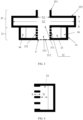
FIG. 2 is a first schematic structural diagram of a vibration absorption apparatus according to an embodiment of this application; -
FIG. 3 is a second schematic structural diagram of a vibration absorption apparatus according to an embodiment of this application; and -
FIG. 4 is a partial schematic structural diagram of a vibration absorption apparatus according to an embodiment of this application. - The following clearly describes the technical solution in the embodiments of this application with reference to the accompanying drawings in the embodiments of this application. Apparently, the described embodiments are only some rather than all of the embodiments of this application. All other embodiments obtained by persons of ordinary skill in the art based on the embodiments of this application shall fall within the protection scope of this application.
- The terms "first", "second", and the like in this specification and claims of this application are used to distinguish between similar objects rather than to describe a specific order or sequence. It should be understood that data used in this way is used interchangeably in appropriate circumstances such that the embodiments of this application can be implemented in other orders than the order illustrated or described herein. In addition, "first" and "second" are usually used to distinguish objects of a same type, and do not restrict a quantity of objects. In addition, "and/or" in the specification and claims represents at least one of the connected objects, and the character "/" generally indicates that the contextually associated objects have an "or" relationship.
- The vibration absorption apparatus and electronic device provided in the embodiments of this application are hereinafter described in detail by using specific embodiments and application scenarios thereof with reference to the accompanying drawings.
- Referring to
FIG. 1, FIG. 1 is a schematic structural diagram of an electronic device according to an embodiment of this application. As shown inFIG. 1 , the electronic device includes ahousing 1, aspeaker 2, and avibration absorption apparatus 3, where thespeaker 2 is disposed within thehousing 1, and afirst cavity 11 is formed between thespeaker 2 and thehousing 1. - The
casing 21 of thespeaker 2 is provided with afirst opening 211, thevibration absorption apparatus 3 is disposed at thefirst opening 211, and the first opening 211 communicates with thefirst cavity 11 through thevibration absorption apparatus 3. - The
vibration absorption apparatus 3 may be assembled separately or integrally formed with thecasing 21 of thespeaker 2. Thevibration absorption apparatus 3 may be an expansion pipe type resonant silencer, a porous material silencer, or the like. This embodiment does not limit the specific structure of thevibration absorption apparatus 3. - In one embodiment, as shown in
FIG. 2 , thevibration absorption apparatus 3 may include: - an
accommodating structure 31 connected to thespeaker 2, where theaccommodating structure 31 includes asound inlet 311 communicating with thefirst opening 211 and asound outlet 312 communicating with thefirst cavity 11, and thesound inlet 311 communicates with thesound outlet 312 to form asound transmission channel 313; and - a perforated
vibration absorption structure 32 disposed within theaccommodating structure 31, where the perforatedvibration absorption structure 32 is provided with a plurality ofperforations 321, asecond cavity 33 is formed between the perforatedvibration absorption structure 32 and theaccommodating structure 31, and theperforations 321 connect thesecond cavity 33 and thesound transmission channel 313. - In one embodiment, as shown in
FIG. 3 , thevibration absorption apparatus 3 may include:
an expansionvibration absorption structure 35, where the expansionvibration absorption structure 35 includes a connectingpipe 351 and anexpansion pipe 352, the connectingpipe 351 is connected to theexpansion pipe 352, the connectingpipe 351 is disposed at thefirst opening 211, and theexpansion pipe 352 communicates with thefirst cavity 11. - It should be noted that the
first opening 211 can connect therear cavity 24 of thespeaker 2 and thefirst cavity 11, allowing the sound emitted by thespeaker 2 to flow from therear cavity 24 of thespeaker 2 through thefirst opening 211 to thefirst cavity 11, which effectively increases the volume of therear cavity 24 of thespeaker 2, thereby enhancing the low-frequency performance of thespeaker 2. - In one embodiment, the
accommodating structure 31 and the perforatedvibration absorption structure 32 constitute a perforated vibration absorption assembly, and thevibration absorption apparatus 3 may include a plurality of perforated vibration absorption assemblies; and/or, thevibration absorption apparatus 3 may include a plurality of expansionvibration absorption structures 35; where - in a case of a plurality of expansion
vibration absorption structures 35, the plurality of expansionvibration absorption structures 35 are connected in series; - in a case of a plurality of perforated vibration absorption assemblies, the plurality of perforated vibration absorption assemblies are connected in series; or
- in a case of a plurality of expansion
vibration absorption structures 35 and a plurality of perforated vibration absorption assemblies, one expansionvibration absorption structure 35 and one perforated vibration absorption assembly are connected in series to form a vibration absorption unit, and a plurality of vibration absorption units are connected in series to form thevibration absorption apparatus 3. - In addition, taking two perforated vibration absorption assemblies connected in series as an example, the
accommodating structure 31 of the first perforated vibration absorption assembly communicates with thefirst opening 211, the perforatedvibration absorption structure 32 of the first perforated vibration absorption assembly communicates with the perforatedvibration absorption structure 32 of the second perforated vibration absorption assembly, theaccommodating structure 31 of the first perforated vibration absorption assembly is connected to theaccommodating structure 31 of the second perforated vibration absorption assembly, and thesound inlet 311 andsound outlet 312 of the first perforated vibration absorption assembly, and the sound inlet 311 andsound outlet 312 of the second perforated vibration absorption assembly form a sound transmission channel, thereby achieving the series connection of two perforated vibration absorption assemblies. The method for connecting a plurality of perforated vibration absorption assemblies in series is similar. - Furthermore, taking two vibration absorption units connected in series as an example, the connecting
pipe 351 of the expansionvibration absorption structure 35 of the first vibration absorption unit communicates with thefirst opening 211, the connectingpipe 351 of the expansionvibration absorption structure 35 of the second vibration absorption unit communicates with theaccommodating structure 31 of the first vibration absorption unit, and the perforatedvibration absorption structure 32 of the second vibration absorption unit communicates with thefirst cavity 11, thereby achieving the series connection of two vibration absorption units. The method for connecting a plurality of vibration absorption units in series is similar. - In this way, air vibrations passing through the multi-channel sound-absorbing structure, which includes a plurality of expansion
vibration absorption structures 35 and/or a plurality of perforatedvibration absorption structures 32, will have their resonant frequency sound waves significantly reduced when transmitted into thefirst cavity 11, greatly reducing the vibration of thehousing 1. - It should be noted that when the back sound waves radiated by the
speaker 2 pass through therear cavity 24, they will continue to pass through thefirst opening 211 and propagate in thefirst cavity 11. The sound waves enter thevibration absorption apparatus 3 through thefirst opening 211, where thevibration absorption apparatus 3 attenuates the sound waves. In one embodiment, the vibration absorption frequency band of thevibration absorption apparatus 3 may include a target frequency, where the target frequency is a resonant frequency at which thehousing 1 resonates with a sound emitted by thespeaker 2. By using thevibration absorption apparatus 3, the sound waves at the target frequency that easily excite the vibration of thehousing 1 are attenuated, while the sound waves in other frequency bands are minimally attenuated or essentially unaffected. When the sound waves pass through thevibration absorption apparatus 3 and enter thefirst cavity 11, the resonance intensity of thehousing 1 is greatly reduced, improving the user experience. - Taking a mobile phone as an example of an electronic device, when the
first opening 211 is not provided, the cavity formed by thecasing 21 of thespeaker 2 is nearly sealed, which can be referred to as a sealed BOX (box). In a sealed BOX, when thespeaker 2 operates, it generates an air pressure change in therear cavity 24 opposite to that in thefront cavity 23. The air pressure change in thefront cavity 23 ultimately propagates to the outside of the mobile phone along the direction of the arrows in thefront cavity 23, forming the sound heard by the user; while the air pressure change in therear cavity 24 is confined within therear cavity 24, with only a negligible amount propagating outward through thecasing 21 of thespeaker 2. Due to the small volume of therear cavity 24 in a sealed BOX, the low-frequency performance of thespeaker 2 is poor. In the embodiment of this application, through the provision of thefirst opening 211 on thecasing 21 of thespeaker 2, the cavity formed by thecasing 21 of thespeaker 2 is no longer sealed, which can be referred to as an open BOX. The airflow inside thecasing 21 of thespeaker 2 can communicate with the airflow inside thefirst cavity 11, increasing the volume of therear cavity 24, thereby enhancing the low-frequency performance of thespeaker 2 and providing a better external sound experience for the mobile phone. - In the embodiment of this application, through the provision of the
first opening 211 on thecasing 21 of thespeaker 2, and thefirst opening 211 communicating with thefirst cavity 11 through thevibration absorption apparatus 3, the internal space of the entire mobile phone can be fully utilized, and the issue of strong vibration sensation at the mobile phone battery cover can be resolved. - It should be noted that the
speaker 2 in the embodiment of this application is particularly suitable for electronic devices with insufficient space and compact structures, such as virtual reality (Virtual Reality, VR) devices, augmented reality (Augmented Reality, AR) devices, mobile phones, tablets, and other electronic devices. - In the embodiment of this application, the electronic device includes a
housing 1, aspeaker 2, and avibration absorption apparatus 3, where thespeaker 2 is disposed within thehousing 1, and afirst cavity 11 is formed between thespeaker 2 and thehousing 1; thecasing 21 of thespeaker 2 is provided with afirst opening 211, thevibration absorption apparatus 3 is disposed at thefirst opening 211, and thefirst opening 211 communicates with thefirst cavity 11 through thevibration absorption apparatus 3. In this way, thefirst opening 211 connects the interior of thespeaker 2 with thefirst cavity 11, allowing the sound emitted by thespeaker 2 to flow through thefirst opening 211 to thefirst cavity 11, thereby enhancing the low-frequency performance of thespeaker 2; furthermore, thevibration absorption apparatus 3 can absorb vibrations to reduce the probability of resonance between thehousing 1 and the sound emitted by thespeaker 2. - Optionally, as shown in
FIG. 2 , thevibration absorption apparatus 3 includes: - an
accommodating structure 31 connected to thespeaker 2, where theaccommodating structure 31 includes asound inlet 311 communicating with thefirst opening 211 and asound outlet 312 communicating with thefirst cavity 11, and thesound inlet 311 communicates with thesound outlet 312 to form a sound transmission channel; and - a perforated
vibration absorption structure 32 disposed within theaccommodating structure 31, where the perforatedvibration absorption structure 32 is provided with a plurality of perforations, asecond cavity 33 is formed between the perforatedvibration absorption structure 32 and theaccommodating structure 31, and the perforations connect thesecond cavity 33 and the sound transmission channel. - The
accommodating structure 31 may be a squareaccommodating structure 31, a circularaccommodating structure 31, or other shapes ofaccommodating structures 31. This embodiment does not limit the shape of theaccommodating structure 31. - In addition, the perforated
vibration absorption structure 32 may be a pipe, with two ends of the pipe respectively communicating with thesound inlet 311 and thesound outlet 312, where thesound inlet 311 and thesound outlet 312 of theaccommodating structure 31 and the pipe form a sound transmission channel; or, a plurality of perforatedvibration absorption structures 32 enclose the sound transmission channel. - It should be noted that the perforated
vibration absorption structure 32 can achieve resonant sound absorption through the plurality of perforations provided. Sound waves act on the perforatedvibration absorption structure 32, causing the perforatedvibration absorption structure 32 to vibrate back and forth, thereby absorbing the sound wave energy and converting it into vibrational energy for dissipation. Typically, the energy of the sound waves is insufficient to cause the perforatedvibration absorption structure 32 to vibrate, and only during resonance does it cause the perforatedvibration absorption structure 32 to vibrate. The resonant frequency of the perforations on the perforatedvibration absorption structure 32 can be changed, thereby changing the frequency of the absorbed sound waves. - In one embodiment, as shown in
FIG. 4 , through the adjustment of the perforation ratio of the perforatedvibration absorption structure 32, the cavity depth D of thesecond cavity 33, and the side wall thickness b of the perforatedvibration absorption structure 32, the resonant frequency of the perforatedvibration absorption structure 32 can be changed, thereby changing the sound absorption frequency of the perforatedvibration absorption structure 32. The sound absorption frequency of the perforatedvibration absorption structure 32 may be the target frequency, where the target frequency is the resonant frequency at which thehousing 1 resonates with the sound emitted by thespeaker 2. - In this way, air vibrations passing through the perforated
vibration absorption structure 32 will have their sound waves significantly reduced when transmitted into thefirst cavity 11, greatly reducing the vibration of thehousing 1. - Optionally, the perforated
vibration absorption structure 32 is a pipe, where two ends of the perforatedvibration absorption structure 32 respectively communicate with thesound inlet 311 and thesound outlet 312, the sound transmission channel is located on an inner side of the perforatedvibration absorption structure 32, and a plurality of perforations are provided on a side wall of the perforatedvibration absorption structure 32;
and/or
thevibration absorption apparatus 3 includes a plurality of perforatedvibration absorption structures 32, and the plurality of perforatedvibration absorption structures 32 enclose the sound transmission channel. - The perforated
vibration absorption structure 32 is a pipe, where the pipe may be a square pipe, a circular pipe, or other shapes of pipes. This is not limited in this embodiment. The perforatedvibration absorption structure 32 may be a pipe formed by a perforated plate. - In addition, the perforated
vibration absorption structure 32 may be a perforated plate, where a plurality of perforated plates enclose the sound transmission channel. - It should be noted that the perforated
vibration absorption structure 32 implements resonant sound absorption through a side wall of the perforatedvibration absorption structure 32. Sound waves act on the side wall, causing the side wall to vibrate back and forth, thereby absorbing the sound wave energy and converting it into vibrational energy for dissipation. - Optionally, as shown in
FIG. 2 , a sound-absorbingmaterial 34 is disposed within thesecond cavity 33. - The sound-absorbing
material 34 may be disposed near the side wall of theaccommodating structure 31 forming thesecond cavity 33. The sound-absorbingmaterial 34 may include hemp velvet, petroleum fiber cotton, sponge, aluminum silicate cotton, and the like. - In this embodiment, the perforated
vibration absorption structure 32 can not only absorb specific frequency sound waves through the perforations on the side wall, but also assist the perforations on the side wall to absorb the specific frequency sound waves through the sound-absorbingmaterial 34 disposed inside thesecond cavity 33, thereby improving the sound absorption effect of the perforatedvibration absorption structure 32. - Optionally, the plurality of perforations provided on the perforated
vibration absorption structure 32 are arranged at intervals along the sound transmission direction, the sound transmission direction pointing from the sound inlet to the sound outlet. - The perforated
vibration absorption structure 32 may be a pipe, and the sound transmission direction may point from the end of the perforatedvibration absorption structure 32 communicating with thesound inlet 311 to the end of the perforatedvibration absorption structure 32 communicating with thesound outlet 312. Through the plurality of perforations arranged at intervals along the sound transmission direction on the perforatedvibration absorption structure 32, a better sound absorption effect can be implemented. - Optionally, the sound absorption frequency of the perforated
vibration absorption structure 32 is a target frequency, where the target frequency is a resonant frequency at which thehousing 1 resonates with the sound emitted by thespeaker 2; where
the sound absorption frequency of the perforatedvibration absorption structure 32 is proportional to a perforation ratio of the perforatedvibration absorption structure 32, inversely proportional to a cavity depth of thesecond cavity 33, and inversely proportional to a side wall thickness of the perforatedvibration absorption structure 32. - In one embodiment, the sound absorption frequency f of the perforated
vibration absorption structure 32 may be:
c is the speed of sound, p is the perforation ratio of the perforatedvibration absorption structure 32, and D is the cavity depth of thesecond cavity 33. - The parameter Lk is:

b is the side wall thickness of the perforatedvibration absorption structure 32. - Optionally, as shown in
FIG. 3 , thevibration absorption apparatus 3 includes: - at least one expansion
vibration absorption structure 35, where the expansionvibration absorption structure 35 includes a connectingpipe 351 and anexpansion pipe 352, the connectingpipe 351 is connected to theexpansion pipe 352, and the connectingpipe 351 is disposed at thefirst opening 211; where - the
expansion pipe 352 is connected to theaccommodating structure 31, and thefirst opening 211 communicates with thefirst cavity 11 sequentially through the connectingpipe 351, theexpansion pipe 352, and the sound transmission channel. - The connecting
pipe 351 may be a square pipe, a circular pipe, or other shapes of pipes. This embodiment does not limit the shape of the connectingpipe 351. Theexpansion pipe 352 may form a hollow cylindrical cavity, a hollow square cavity, or a cavity of other shapes. This embodiment does not limit the shape of the cavity formed by theexpansion pipe 352. - In one embodiment, the connecting
pipe 351 is a circular pipe, and theexpansion pipe 352 forms a hollow cylindrical cavity. - In one embodiment, a diameter of the pipe formed by the perforated
vibration absorption structure 32 may be the same as the diameter of the pipe of the connectingpipe 351. - In one embodiment, the
expansion pipe 352 is provided with a second opening and a third opening respectively on its two opposite side walls, where the second opening communicates with the perforatedvibration absorption structure 32, and the third opening communicates with the connectingpipe 351. - A cross-sectional area of the second opening may be the same as a cross-sectional area of the pipe formed by the perforated
vibration absorption structure 32, where the cross-sectional area of the pipe is an area of a cross-section perpendicular to the centerline of the pipe. A cross-sectional area of the third opening may be the same as a cross-sectional area of the connectingpipe 351, where the cross-sectional area of the connectingpipe 351 is an area of a cross-section perpendicular to the centerline of the connectingpipe 351. - In one embodiment, the cross-sectional area of the pipe formed by the perforated
vibration absorption structure 32 may be the same as the cross-sectional area of the connectingpipe 351, facilitating the flow of sound waves from the pipe formed by the perforatedvibration absorption structure 32 to the connectingpipe 351, providing a better transmission path for the sound waves. - In this way, air vibrations passing through the two-channel sound-absorbing structure, which includes the expansion
vibration absorption structure 35 and the perforatedvibration absorption structure 32, will have their target frequency sound waves significantly reduced when transmitted into thefirst cavity 11, greatly reducing the vibration of thehousing 1. - Optionally, the
vibration absorption apparatus 3 includes:
an expansionvibration absorption structure 35, where the expansionvibration absorption structure 35 includes a connectingpipe 351 and anexpansion pipe 352, the connectingpipe 351 is connected to theexpansion pipe 352, and the connectingpipe 351 is disposed at thefirst opening 211, and thefirst opening 211 communicates with thefirst cavity 11 through the connectingpipe 351 and theexpansion pipe 352. - The length of the pipe of the
expansion pipe 352 may be one-quarter of a target frequency, where the target frequency is the resonant frequency at which thehousing 1 resonates with the sound emitted by thespeaker 2. - In one embodiment, a sound transmission coefficient of the expansion
vibration absorption structure 35 may be:
FIG. 3 , S2 is the cross-sectional area of theexpansion pipe 352, S1 is the cross-sectional area of the connectingpipe 351, and T is a length of theexpansion pipe 352. According to the formula for the sound transmission coefficient, when the length T of theexpansion pipe 352 is one-quarter of the wavelength of the sound wave, the sound transmission coefficient is minimized, and the reflection coefficient is the strongest, which can effectively reduce noise. - Optionally, the
vibration absorption apparatus 3 includes a plurality of expansionvibration absorption structures 35, where theexpansion pipe 352 of one expansionvibration absorption structure 35 is connected to the connectingpipe 351 of another adjacent expansionvibration absorption structure 35. - For example, taking two expansion
vibration absorption structures 35 connected in series as an example, the connectingpipe 351 of the first expansionvibration absorption structure 35 communicates with thefirst opening 211, the connectingpipe 351 of the second expansionvibration absorption structure 35 communicates with theexpansion pipe 352 of the first expansionvibration absorption structure 35, and theexpansion pipe 352 of the second expansionvibration absorption structure 35 communicates with thefirst cavity 11, thereby achieving a series connection of the two expansionvibration absorption structures 35. The method of connecting a plurality of expansionvibration absorption structures 35 in series is similar. - Optionally, as shown in
FIG. 1 , thespeaker 2 includes adiaphragm 22, where thediaphragm 22 divides thespeaker 2 into afront cavity 23 and arear cavity 24, thefront cavity 23 communicates with thesound outlet hole 25 of thespeaker 2, thefirst opening 211 is disposed on a side wall of thecasing 21 forming therear cavity 24, and therear cavity 24 communicates with thefirst cavity 11 through thefirst opening 211 and thevibration absorption apparatus 3. - The
front cavity 23 and therear cavity 24 may be isolated from each other. - Optionally, the vibration absorption frequency band of the
vibration absorption apparatus 3 includes a target frequency, where the target frequency is a resonant frequency at which thehousing 1 resonates with a sound emitted by thespeaker 2. - It should be noted that if the frequency of the airflow caused by the sound emitted by the
speaker 2 and leaked to thehousing 1 is near the target frequency, thehousing 1 itself will resonate. Through the provision of thevibration absorption apparatus 3, where thevibration absorption apparatus 3 has a vibration absorption frequency band that includes the target frequency, thevibration absorption apparatus 3 can reduce the airflow, with a frequency of the airflow near the target frequency, in thehousing 1 caused by the sound emitted by thespeaker 2 and leaked to thehousing 1, thereby reducing the possibility of resonance between thehousing 1 and the sound emitted by thespeaker 2, and potentially eliminating resonance. - In one embodiment, the center frequency of the vibration absorption frequency band of the
vibration absorption apparatus 3 is the target frequency. - The
vibration absorption apparatus 3 has the best absorption effect on the airflow at the center frequency of the vibration absorption frequency band. For example, the maximum value of the vibration absorption frequency of thevibration absorption apparatus 3 may be frequency a, the minimum value of the vibration absorption frequency of thevibration absorption apparatus 3 may be frequency b, and the center frequency of the vibration absorption frequency band of thevibration absorption apparatus 3 may be (a+b)/2. - In this way, the
vibration absorption apparatus 3 can better eliminate the airflow near the target frequency, further reducing the possibility of resonance between thehousing 1 and the sound emitted by thespeaker 2. - Optionally, the electronic device further includes a damping
mesh 4 provided between thevibration absorption apparatus 3 and thehousing 1, where thefirst opening 211 communicates with thefirst cavity 11 through thevibration absorption apparatus 3 and the dampingmesh 4. - The
vibration absorption apparatus 3 may include anaccommodating structure 31, as shown inFIG. 3 , and the dampingmesh 4 may be provided at thesound outlet 312 of theaccommodating structure 31. The dampingmesh 4 may be a mesh fabric with high acoustic resistance. Through the provision of the dampingmesh 4 between thevibration absorption apparatus 3 and thehousing 1, the air pressure changes of the airflow passing through the dampingmesh 4 can be effectively reduced, thereby implementing the effect of balancing air pressure. - An embodiment of this application embodiment further provides a
vibration absorption apparatus 3, where thevibration absorption apparatus 3 includes: - an
accommodating structure 31 including asound inlet 311 and asound outlet 312, where thesound inlet 311 communicates with thesound outlet 312 to form a sound transmission channel; and - a perforated
vibration absorption structure 32 disposed within theaccommodating structure 31, where the perforatedvibration absorption structure 32 is provided with a plurality of perforations, asecond cavity 33 is formed between the perforatedvibration absorption structure 32 and theaccommodating structure 31, and the perforations connect thesecond cavity 33 and the sound transmission channel. - Optionally, the perforated
vibration absorption structure 32 is a pipe, where two ends of the perforatedvibration absorption structure 32 respectively communicate with thesound inlet 311 and thesound outlet 312, the sound transmission channel is located on an inner side of the perforatedvibration absorption structure 32, and a plurality of perforations are provided on a side wall of the perforatedvibration absorption structure 32;
and/or
thevibration absorption apparatus 3 includes a plurality of perforatedvibration absorption structures 32, and the plurality of perforatedvibration absorption structures 32 enclose the sound transmission channel. - Optionally, a sound-absorbing
material 34 is disposed within thesecond cavity 33. - Optionally, the plurality of perforations provided on the perforated
vibration absorption structure 32 are arranged at intervals along the sound transmission direction. - Optionally, the sound absorption frequency of the perforated
vibration absorption structure 32 is proportional to a perforation ratio of the perforatedvibration absorption structure 32, inversely proportional to a cavity depth of thesecond cavity 33, and inversely proportional to a side wall thickness of the perforatedvibration absorption structure 32. - Optionally, the
vibration absorption apparatus 3 includes: - at least one expansion
vibration absorption structure 35, where the expansionvibration absorption structure 35 includes a connectingpipe 351 and anexpansion pipe 352, and the connectingpipe 351 is connected to theexpansion pipe 352; where - the
expansion pipe 352 is connected to theaccommodating structure 31. - An embodiment of this application embodiment further provides a
vibration absorption apparatus 3, where thevibration absorption apparatus 3 includes:
an expansionvibration absorption structure 35, where the expansionvibration absorption structure 35 includes a connectingpipe 351 and anexpansion pipe 352, and the connectingpipe 351 is connected to theexpansion pipe 352. - An embodiment of this application further provides an electronic device, where the electronic device includes the vibration absorption apparatus described in the embodiments of this application.
- The electronic device in the embodiments of this application may be a mobile electronic device or a non-mobile electronic device. For example, the mobile electronic device may be a mobile phone, a tablet computer, a notebook computer, a palmtop computer, a vehicle-mounted electronic device, a wearable device, an ultra-mobile personal computer (ultra-mobile personal computer, UMPC), a netbook, or a personal digital assistant (personal digital assistant, PDA), and the non-mobile electronic device may be a personal computer (personal computer, PC), a television (television, TV), a teller machine, a self-service machine, or the like. This is not specifically limited in the embodiments of this application.
- It should be noted that in this specification, the terms "include" and "comprise", or any of their variants are intended to cover a non-exclusive inclusion, such that a process, method, article, or apparatus that includes a list of elements not only includes those elements but also includes other elements that are not expressly listed, or further includes elements inherent to such process, method, article, or apparatus. In absence of more constraints, an element preceded by "includes a..." does not preclude the existence of other identical elements in the process, method, article, or apparatus that includes the element. Furthermore, it should be noted that the scope of the method and apparatus in the implementations of this application is not limited to functions being performed in the order shown or discussed, but may further include functions being performed at substantially the same time or in a reverse order, depending on the functions involved. For example, the described method may be performed in an order different from that described, and various steps may be added, omitted, or combined. In addition, features described with reference to some examples may be combined in other examples.
- The foregoing describes the embodiments of this application with reference to the accompanying drawings. However, this application is not limited to the foregoing specific embodiments. The foregoing specific embodiments are merely illustrative rather than restrictive. As instructed by this application, persons of ordinary skill in the art may develop many other manners without departing from principles of this application and the protection scope of the claims, and all such manners fall within the protection scope of this application.
Claims (13)
- An electronic device, the electronic device comprising a housing (1), a speaker (2), and a vibration absorption apparatus (3), wherein the speaker (2) is disposed within the housing (1), and a first cavity (11) is formed between the speaker (2) and the housing (1); wherein
a casing (21) of the speaker (2) is provided with a first opening (211), the vibration absorption apparatus (3) is disposed at the first opening (211), and the first opening (211) communicates with the first cavity (11) through the vibration absorption apparatus (3). - The electronic device according to claim 1, wherein the vibration absorption apparatus (3) comprises:an accommodating structure (31) connected to the speaker (2), wherein the accommodating structure (31) comprises a sound inlet (311) communicating with the first opening (211) and a sound outlet (312) communicating with the first cavity, and the sound inlet (311) communicates with the sound outlet (312) to form a sound transmission channel; anda perforated vibration absorption structure (32) disposed within the accommodating structure (31), wherein the perforated vibration absorption structure (32) is provided with a plurality of perforations, a second cavity (33) is formed between the perforated vibration absorption structure (32) and the accommodating structure (31), and the perforations connect the second cavity (33) and the sound transmission channel.
- The electronic device according to claim 2, wherein the perforated vibration absorption structure (32) is a pipe, two ends of the perforated vibration absorption structure (32) respectively communicate with the sound inlet (311) and the sound outlet (312), the sound transmission channel is located on an inner side of the perforated vibration absorption structure (32), and a plurality of perforations are provided on a side wall of the perforated vibration absorption structure (32);
and/or
the vibration absorption apparatus (3) comprises a plurality of perforated vibration absorption structures (32), and the plurality of perforated vibration absorption structures (32) enclose the sound transmission channel. - The electronic device according to claim 2, wherein a sound-absorbing material (34) is disposed within the second cavity (33).
- The electronic device according to claim 2, wherein the plurality of perforations provided on the perforated vibration absorption structure (32) are arranged at intervals along a sound transmission direction, wherein the sound transmission direction points from the sound inlet to the sound outlet.
- The electronic device according to claim 2, wherein a sound absorption frequency of the perforated vibration absorption structure (32) comprises a target frequency, wherein the target frequency is a resonant frequency at which the housing (1) resonates with a sound emitted by the speaker (2); wherein
the sound absorption frequency of the perforated vibration absorption structure (32) is proportional to a perforation ratio of the perforated vibration absorption structure (32), inversely proportional to a cavity depth of the second cavity (33), and inversely proportional to a side wall thickness of the perforated vibration absorption structure (32). - The electronic device according to claim 2, wherein the vibration absorption apparatus (3) comprises:at least one expansion vibration absorption structure (35), wherein the expansion vibration absorption structure (35) comprises a connecting pipe (351) and an expansion pipe (352), the connecting pipe (351) is connected to the expansion pipe (352), and the connecting pipe (351) is disposed at the first opening (211); whereinthe expansion pipe (352) is connected to the accommodating structure (31), the first opening (211) communicates with the first cavity (11) sequentially through the connecting pipe (351), the expansion pipe (352), and the sound transmission channel.
- The electronic device according to claim 1, wherein the vibration absorption apparatus (3) comprises:
an expansion vibration absorption structure (35), wherein the expansion vibration absorption structure (35) comprises a connecting pipe (351) and an expansion pipe (352), the connecting pipe (351) is connected to the expansion pipe (352), the connecting pipe (351) is disposed at the first opening (211), and the first opening (211) communicates with the first cavity (11) through the connecting pipe (351) and the expansion pipe (352). - The electronic device according to claim 7, wherein the vibration absorption apparatus (3) comprises a plurality of expansion vibration absorption structures (35), wherein the expansion pipe (352) of the expansion vibration absorption structure (35) is connected to a connecting pipe (351) of another adjacent expansion vibration absorption structure (35).
- The electronic device according to claim 1, wherein the speaker (2) comprises a diaphragm (22), the diaphragm (22) divides the speaker into a front cavity (23) and a rear cavity (24), the front cavity (23) communicates with a sound outlet hole (25) of the speaker, the first opening (211) is disposed on a side wall of the casing (21) forming the rear cavity (24), and the rear cavity communicates with the first cavity (11) through the first opening (211) and the vibration absorption apparatus (3).
- The electronic device according to claim 1, wherein a vibration absorption frequency band of the vibration absorption apparatus (3) comprises a target frequency, and the target frequency is a resonant frequency at which the housing (1) resonates with a sound emitted by the speaker (2).
- The electronic device according to claim 1, wherein the electronic device further comprises a damping mesh (4) disposed between the vibration absorption apparatus (3) and the housing, and the first opening (211) communicates with the first cavity (11) through the vibration absorption apparatus (3) and the damping mesh (4).
- A vibration absorption apparatus, wherein the vibration absorption apparatus comprises:an accommodating structure (31) comprising a sound inlet (311) and a sound outlet (312), wherein the sound inlet (311) communicates with the sound outlet (312) to form a sound transmission channel; anda perforated vibration absorption structure (32) disposed within the accommodating structure (31), wherein the perforated vibration absorption structure (32) is provided with a plurality of perforations, a second cavity (33) is formed between the perforated vibration absorption structure (32) and the accommodating structure (31), and the perforations connect the second cavity (33) and the sound transmission channel.
Applications Claiming Priority (2)
| Application Number | Priority Date | Filing Date | Title |
|---|---|---|---|
| CN202210573829.5A CN114979891B (en) | 2022-05-24 | 2022-05-24 | Vibration absorbing device and electronic equipment |
| PCT/CN2023/094716 WO2023226843A1 (en) | 2022-05-24 | 2023-05-17 | Vibration absorption device and electronic equipment |
Publications (2)
| Publication Number | Publication Date |
|---|---|
| EP4535822A1 true EP4535822A1 (en) | 2025-04-09 |
| EP4535822A4 EP4535822A4 (en) | 2025-08-20 |
Family
ID=82955415
Family Applications (1)
| Application Number | Title | Priority Date | Filing Date |
|---|---|---|---|
| EP23810916.9A Pending EP4535822A4 (en) | 2022-05-24 | 2023-05-17 | VIBRATION DAMPING DEVICE AND ELECTRONIC EQUIPMENT |
Country Status (4)
| Country | Link |
|---|---|
| US (1) | US20250071475A1 (en) |
| EP (1) | EP4535822A4 (en) |
| CN (1) | CN114979891B (en) |
| WO (1) | WO2023226843A1 (en) |
Families Citing this family (3)
| Publication number | Priority date | Publication date | Assignee | Title |
|---|---|---|---|---|
| CN114979891B (en) * | 2022-05-24 | 2025-02-07 | 维沃移动通信有限公司 | Vibration absorbing device and electronic equipment |
| CN219960824U (en) * | 2023-01-20 | 2023-11-03 | 镇江贝斯特新材料股份有限公司 | Vibration-absorbing structures and electronic equipment |
| CN119277277A (en) * | 2024-09-30 | 2025-01-07 | 维沃移动通信有限公司 | Electronic equipment |
Family Cites Families (11)
| Publication number | Priority date | Publication date | Assignee | Title |
|---|---|---|---|---|
| US7578368B2 (en) * | 2007-03-07 | 2009-08-25 | Foxconn Technology Co., Ltd. | Speaker set for electronic product |
| CN201450572U (en) * | 2009-07-16 | 2010-05-05 | 徐江 | Sound box |
| CN104754454B (en) * | 2015-03-25 | 2019-03-26 | 歌尔股份有限公司 | Loudspeaker mould group |
| CN206181362U (en) * | 2016-10-25 | 2017-05-17 | 瑞声声学科技(深圳)有限公司 | Sounding device |
| CN207531068U (en) * | 2017-11-02 | 2018-06-22 | 瑞声科技(新加坡)有限公司 | Loudspeaker enclosure |
| WO2019146096A1 (en) * | 2018-01-29 | 2019-08-01 | ヤマハ株式会社 | Audio output device |
| CN112533114B (en) * | 2019-09-18 | 2022-05-13 | 华为技术有限公司 | Sounding device and electronic equipment |
| CN113596672B (en) * | 2020-04-30 | 2022-11-22 | 华为技术有限公司 | Loudspeaker module and electronic equipment |
| CN214012498U (en) * | 2020-10-29 | 2021-08-20 | 上海超颖声学科技有限公司 | Broadband sound absorption structure |
| CN113938788B (en) * | 2021-10-14 | 2024-07-19 | 维沃移动通信有限公司 | Audio output device and electronic device |
| CN114979891B (en) * | 2022-05-24 | 2025-02-07 | 维沃移动通信有限公司 | Vibration absorbing device and electronic equipment |
-
2022
- 2022-05-24 CN CN202210573829.5A patent/CN114979891B/en active Active
-
2023
- 2023-05-17 WO PCT/CN2023/094716 patent/WO2023226843A1/en not_active Ceased
- 2023-05-17 EP EP23810916.9A patent/EP4535822A4/en active Pending
-
2024
- 2024-11-14 US US18/947,078 patent/US20250071475A1/en active Pending
Also Published As
| Publication number | Publication date |
|---|---|
| CN114979891A (en) | 2022-08-30 |
| WO2023226843A1 (en) | 2023-11-30 |
| CN114979891B (en) | 2025-02-07 |
| US20250071475A1 (en) | 2025-02-27 |
| EP4535822A4 (en) | 2025-08-20 |
Similar Documents
| Publication | Publication Date | Title |
|---|---|---|
| US20250071475A1 (en) | Vibration absorption apparatus and electronic device | |
| EP2868116B1 (en) | Loudspeaker having an acoustic filter | |
| CN116733787B (en) | A three-dimensional composite metamorphic muffler module and muffler | |
| WO2020024522A1 (en) | Sound generation apparatus and portable terminal | |
| CN113938788A (en) | Audio output device and electronic equipment | |
| CN114745631A (en) | Sounder module and intelligent head-mounted equipment | |
| CN210579210U (en) | Loudspeaker module and electronic equipment | |
| CN109348380A (en) | Sounding device and portable terminal | |
| Wu et al. | Sonic black hole coupled with membrane-type acoustic metamaterial for broadband and low-frequency sound absorption | |
| US20240139034A1 (en) | Earpad comprising one or more resonators | |
| EP1992192B1 (en) | Sound sponge for loudspeakers | |
| TWI669968B (en) | Speaker module | |
| CN112995843A (en) | Electronic device | |
| EP1542496B1 (en) | Loudspeaker enclosure incorporating a leak to compensate for the effect of acoustic modes on loudspeaker frequency response | |
| US10645485B2 (en) | Extension system of woofer and design method thereof | |
| CN111833839A (en) | A high-performance sound-absorbing structure | |
| US11570532B2 (en) | Electronic device with loudspeaker module | |
| CN115445036A (en) | Breathing equipment noise eliminator | |
| CN103428612B (en) | Loudspeaker | |
| CN119156835A (en) | Loudspeaker | |
| CN115515059B (en) | Speaker modules and electronic devices | |
| EP4080906A1 (en) | Helmholtz resonators to scale down loudspeaker enclosure size and enhance performance | |
| CN202068556U (en) | Acoustical device for handheld electronic equipment | |
| CN211451501U (en) | Noise reduction panels, refrigerators | |
| Nguyen | Development of acoustic metamaterials for efficient sound control and noise mitigation |
Legal Events
| Date | Code | Title | Description |
|---|---|---|---|
| STAA | Information on the status of an ep patent application or granted ep patent |
Free format text: STATUS: THE INTERNATIONAL PUBLICATION HAS BEEN MADE |
|
| PUAI | Public reference made under article 153(3) epc to a published international application that has entered the european phase |
Free format text: ORIGINAL CODE: 0009012 |
|
| STAA | Information on the status of an ep patent application or granted ep patent |
Free format text: STATUS: REQUEST FOR EXAMINATION WAS MADE |
|
| 17P | Request for examination filed |
Effective date: 20240912 |
|
| AK | Designated contracting states |
Kind code of ref document: A1 Designated state(s): AL AT BE BG CH CY CZ DE DK EE ES FI FR GB GR HR HU IE IS IT LI LT LU LV MC ME MK MT NL NO PL PT RO RS SE SI SK SM TR |
|
| A4 | Supplementary search report drawn up and despatched |
Effective date: 20250722 |
|
| RIC1 | Information provided on ipc code assigned before grant |
Ipc: H04R 1/28 20060101AFI20250716BHEP |
|
| DAV | Request for validation of the european patent (deleted) | ||
| DAX | Request for extension of the european patent (deleted) |